Automated Eddy Current Inspections of Complex, Irregular Surfaces
|
|
|
- Millicent Caldwell
- 5 years ago
- Views:
Transcription
1 Automated Eddy Current Inspections of Complex, Irregular Surfaces Eric Shell, Matt Gardner Wyle Dayton, OH ATA NDT Forum 23 Sept 2010

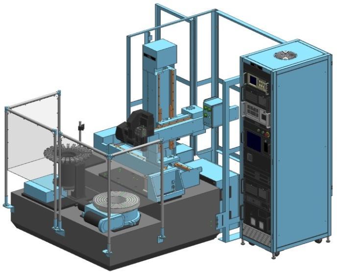
2 Background Wyle s 7-axis Eddy Current Inspection System (ECIS) is used by the USAF and allied nations to inspect military engine components for: Small surface cracks Machining-induced surface anomalies Fully automated operator loads the part and necessary probes, enters part number identification information, and presses start All steps of the inspection are independent of the operator: Instrument setup / standardization of sensitivity Part scanning and data collection Data analysis Data archiving Accept / Reject of part
3 New Challenge Most geometries can be programmed using a few simple equation-based axis movements Most engine components have tight dimensional tolerances Recent more complex geometries require: up to 6 coordinated axes probes with an automated indexing axis Attention is required to ensure: Probe stays normal and in contact during inspection Sufficient coverage with the expected flaw sensitivity
4 Overview An inspection development method was created to automate robot manipulation programming and inspection of complex surfaces: Scan contours mapped from solid model of part Part coordinate data are extracted to text files Automated creation of scan plan software Recent ECIS hardware/software improvements allow inspection of complex regions and shapes Results in an easier implementation for high resolution scanning of complex surfaces

5 Example Inspection Area Cylindrical feature that is askew from the conical OD Must inspect the nonuniform fillet radius and around the base of the fillet Not easily defined by Cartesian coordinate equations Many possible ways to transform scanning into machine axes
6 Approach 1. Define scans in the 3D solid model cad file 2. Extract scan coordinates to a massive text file 3. Parse the file to obtain part local coordinates 4. Matlab-based development program: analyzes and organizes the scan points calculates machine coordinates based on the specific probe dimensions creates CNC commands and ECIS code to control the probe scanning and inspection processing

7 Scan Definition 3D solid model of the part is used to define scan coordinates that cover the requirement area Unigraphics NX6 with Advanced Designer Bundle

8 Scan Definition Procedure Extract isocline curves at the required index spacing Each isocline curve is defined by the fixed probe tip angle and probe body axis angle

9 Scan Definition Procedure Abnormal ovoid curve isocline created near base of the fillet This fillet angle is small enough angle that the compliance of the shoe will keep it normal to the surface Abnormal cluster is removed

10 Scan Definition Procedure Continue scan curves by offsetting by the index distance to encompass the required inspection surface area The probe and sensor are aligned normal to the part side wall
11 Scan Definition Procedure Local working coordinate system is created for the feature Coordinate system origin is located at bottom center of the part Z-axis is aligned to the part axis of rotation X-axis is aligned along the axis of the desired feature Z X
12 Scan Definition Procedure Create point sets along each curve at a specified incremental arc length These points are then queried for their locations with respect to the working coordinate system Results in a large text file with a lot of needless data
 A search for XC, YC, ZC gives needed")
13 Raw Output File As an example, there are 24,562 coordinate points for this feature A lot of extra information is included (most already deleted here) A search for XC, YC, ZC gives needed data
14 Part Scan Coordinates The output file is parsed and reorganized into individual scans Minimize the number of simultaneous scanning axes Keep the sensor normal to the part This geometry requires 4 axes to scan and 4 additional axes (including one on the probe) to index between scans and geometries
15 7.4 Machine Scan Coordinates Part coordinates must be transformed into machine coordinates Account for the probe dimensions and variable tip angle Specify active and inactive axes
16 Inspection Probe and Sensor Probe has a small footprint with an adjustable angle shoe to match the isoclines as extracted from the solid model The probe tip angle can be adjusted between scans but not while scanning A split D differential reflection sensor is used to minimize environmental and geometrical signals while providing sensitivity to small surface cracks

17 Inspection The tip angle and probe axis angle is incremented each scan to keep coil normal to surface

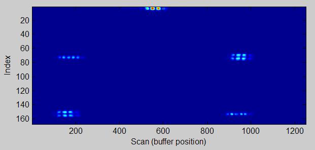
18 Inspection Results A notched feature was inspected, resulting in a somewhat confusing set of eddy current A-scans or scan buffers of varying lengths:


19 Inspection Data C-scan An easier visualization of the data would be a transformed rectangular C-scan plotted in degrees to align radial features
20 Data Processing Filtering is performed to improve the flaw S:N ratio and suppress geometry-related signals Analog HP filter is applied to avoid DC saturation of the digital signal sampler A filter similar to a rectifying bandpass is applied prior to signal thresholding for flaw detection

21 Data Visualization A polar 3D plotting tool has been created to view the data in a more intuitive display Allows easy identification of location of indications

22 Data Visualization (3D) With registration of the inspection data into part coordinates, the data can be plotted on a solid model. The inspection data can provide feedback on: - machining issues - lifing model - potential crack initiation sites
23 Future Application Some geometries may have large dimensional tolerances, yet require inspection for small surface defects or cracks IBR / Blisk blade repairs, for example In this case, we could use the presented algorithm to generate automated scan patterns from CMM data, obtained on the ECIS or from customer-supplied data The inspection scanning would be automatically customized to the dimensions of each specific part
24 Data Presentation As the collection of data becomes more complex, there is an increasing need for tools to display, process, and analyze the data more intuitively With the permanent digital record of inspection data, many new capabilities are enabled
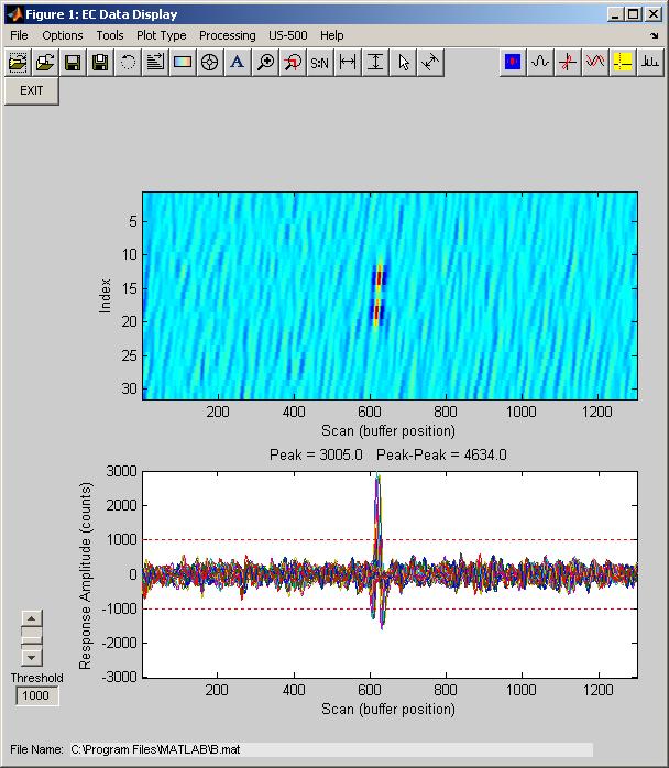
25 ECView Program New Matlab-based program created for: Data Visualization, Manipulation, and Analysis Inspection Development and Debugging Displaying Data on CAD Models Performing Signal Measurements and Analysis Flaw Characterization Offline Signal Processing and Algorithm Development Virtual Re-Inspection of Archived Data Comprehensive capabilities for importing and exporting of data or images into common formats Images (.png,.jpg,.bmp,.tif,.pdf) Data (.csv,.txt,.prn,.mat) Customer-driven automated flaw reports
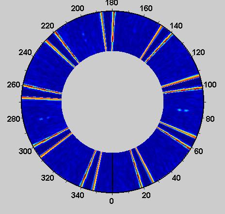


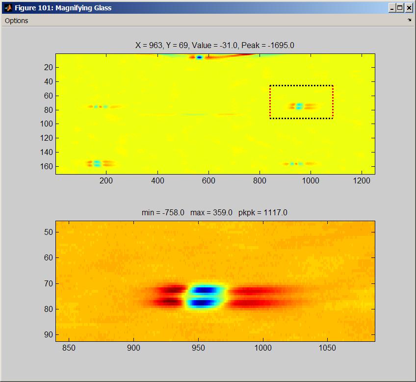
26 ECview Visualization Movable pointer Movable zoom window Polar plotting of surfaces
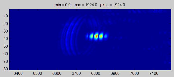

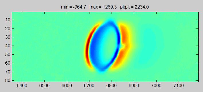

27 ECview Development/Debugging Coverage Verification Signal Processing Algorithm Development S:N = 0.3 S:N = 3.1


28 ECview 3D Plotting Plotting of data on solid part models Could be used with FEA models Helps visualize machining issues 23 September 2010


29 ECview Measurements Signal Statistics Linear Distance Frequency Signal to Noise 23 September 2010


30 ECview Signal Processing Hardware/software frequency filter simulation Replication of ECIS-proprietary filters Platform for new signal processing development 23 September 2010

31 ECview Virtual Re-Inspection Capability to re-process archived raw inspection data while effectively changing: calibration characteristics (notch values, phase rotation, processing) inspection threshold / flaw size requirements signal processing algorithms Enables retroactive requirement changes Enables more efficient algorithm development collect once, then optimize processing Easily modified for various re-inspection goals 23 September 2010
32 ECview Input / Output Input Options: All ECIS raw data files (.prn) Delimited text files (.csv,.txt) Matlab files (.mat) Binary ECIS database files (.dat,.#) Aerotech Nscope files (.nsc) Output Options: Delimited text files Excel workbook Matlab files Image files (.png,.jpg,.bmp,.tif,.pdf) 23 September 2010
33 Summary A generalized inspection routine has been developed to inspect along curves defined in a 3D solid model. The approach has been validated on complex fillets. A new postprocessing / data visualization program has been developed that will allow for further indication characterization.
34 Questions? (937)
John R. Mandeville Senior Consultant NDICS, Norwich, CT Jesse A. Skramstad President - NDT Solutions Inc., New Richmond, WI
 Enhanced Defect Detection on Aircraft Structures Automatic Flaw Classification Software (AFCS) John R. Mandeville Senior Consultant NDICS, Norwich, CT Jesse A. Skramstad President - NDT Solutions Inc.,
Ch 22 Inspection Technologies
 Ch 22 Inspection Technologies Sections: 1. Inspection Metrology 2. Contact vs. Noncontact Inspection Techniques 3. Conventional Measuring and Gaging Techniques 4. Coordinate Measuring Machines 5. Surface
Riser Bolt Inspection
 Riser Bolt Inspection Application Solution 1 Overview Inspection Challenge Recommended Phased Array Ultrasonic (PA UT) Solution Results Benefits of Zetec Solution 2 Inspection Challenge Riser bolts require
ULTRAVISION 3.7R21. Product Bulletin. UltraVision, a complete UT and Phased Array inspection package!
 ULTRAVISION 3.7R21 Product Bulletin UltraVision, a complete UT and Phased Array inspection package! www.zetec.com Table of Content Table of Content... 2 Purpose of UltraVision 3.7R21... 3 Corrosion...
Software Form Control
 Measurement by mouse click. That's how easy workpiece inspection in the machining centre is with the help of FormControl measurement software. It makes no difference whether the workpiece has a freeform
STATUS 5. A Reliability Assessment Tool For NDT Inspection Systems
 STATUS 5 A Reliability Assessment Tool For NDT Inspection Systems STATUS 5 Overview Introduction Advantages Introduction STATUS 5 is a convenient NDT tool for assessing the efficiency and reliability of
New Approach in Non- Contact 3D Free Form Scanning
 New Approach in Non- Contact 3D Free Form Scanning Contents Abstract Industry Trends The solution A smart laser scanning system Implementation of the laser scanning probe in parts inspection Conclusion
3D INTELLIGENDT MODELING AND VISUALIZATION SOFTWARE FOR UT INSPECTIONS OF COMPLEX GEOMETRIES
 3D INTELLIGENDT MODELING AND VISUALIZATION SOFTWARE FOR UT INSPECTIONS OF COMPLEX GEOMETRIES Guenter Guse, Ludwig Bucklisch, Friedrich Mohr, Gordon Huenies AREVA NDE-Solutions /intelligendt System and
ScanMaster. Aluminum Plate Inspection Using Phased Array Technology
 Aluminum Plate Inspection Using Phased Array Technology PA Basics Applied: Electronic Scanning Spatial scanning by driving an active active aperture in a predefined sequence Faster inspection as there
Computer Integrated Manufacturing
 Computer Integrated anufacturing Performance Objectives 1 Fundamentals Demonstrate the ability to store, retrieve copy, and output drawing files depending upon system setup. Show-e Content Show-e Goals
Improved Efficiency for Multi-Technology Inspections (UT and ECT)
") Improved Efficiency for Multi-Technology Inspections (UT and ECT) More info about this article: http://www.ndt.net/?id=22727 Abstract Michaël Monette 1, Lance Maggy 2, Yannick Bellerive 3 Dirk Verspeelt
Improved Efficiency for Multi-Technology Inspections (UT and ECT) More info about this article: http://www.ndt.net/?id=22727 Abstract Michaël Monette 1, Lance Maggy 2, Yannick Bellerive 3 Dirk Verspeelt
Strategy. Using Strategy 1
 Strategy Using Strategy 1 Scan Path / Strategy It is important to visualize the scan path you want for a feature before you begin taking points on your part. You want to try to place your points in a way
UNIT IV - Laser and advances in Metrology 2 MARKS
 UNIT IV - Laser and advances in Metrology 2 MARKS 81. What is interferometer? Interferometer is optical instruments used for measuring flatness and determining the lengths of slip gauges by direct reference
Impact of 3D Laser Data Resolution and Accuracy on Pipeline Dents Strain Analysis
 More Info at Open Access Database www.ndt.net/?id=15137 Impact of 3D Laser Data Resolution and Accuracy on Pipeline Dents Strain Analysis Jean-Simon Fraser, Pierre-Hugues Allard Creaform, 5825 rue St-Georges,
INSPECTION OF THE TURBINE BLADES USING SCANNING TECHNIQUES
 INSPECTION OF THE TURBINE BLADES USING SCANNING TECHNIQUES H. Nieciag, M. Traczynski and Z. Chuchro Department of Geometrical Quanities Metrology The Institute of Metal Cutting, 30-011 Cracow, Poland Abstract:
Other Major Component Inspection I
 Other Major Component Inspection I Mechanized UT inspections on complex nozzle geometries S. Farley, R. Jansohn, Westinghouse Electric Germany, Germany; H. Ernst, Schweizerischer Verein für technische
Calypso the Easy Way to Create Part Programs
 Industrial Measuring Technology from Carl Zeiss Calypso the Easy Way to Create Part Programs We make it visible. Philosophy Visual Metrology TM CAD model feature characteristics Elements are selected to
VisionGauge OnLine Spec Sheet
 VisionGauge OnLine Spec Sheet VISIONx INC. www.visionxinc.com Powerful & Easy to Use Intuitive Interface VisionGauge OnLine is a powerful and easy-to-use machine vision software for automated in-process
Magnetic Field Mapping System MMS-1-RS KEY FEATURES:
 KEY FEATURES: Maximal Scanning volume (X x Y x Z): - standard: 135 x 135 x 135 mm 3 - optional: 500 x 500 x 135 mm 3 Scanning speed: - standard: adjustable, up to 50 mm/s - optional: adjustable, up to
3. Preprocessing of ABAQUS/CAE
 3.1 Create new model database 3. Preprocessing of ABAQUS/CAE A finite element analysis in ABAQUS/CAE starts from create new model database in the toolbar. Then save it with a name user defined. To build
Industrial Measuring Technology from Carl Zeiss. Form, Contour and Surface. Measuring and Testing Precision from Carl Zeiss
 Industrial Measuring Technology from Carl Zeiss Form, Contour and Surface. Measuring and Testing Precision from Carl Zeiss Workshop Measuring Equipment from Carl Zeiss. The advantage of precision. Carl
(Part ##) SWA
 SWA") Item Inspection SW Application for ISONIC 3510 - Phased Array Modality: Expert ARing - Inspection of Annular Ring Critical Zone: Fillet Weld Area Up to 100 mm (4 inch) Inside Above Ground Storage Tank
Item Inspection SW Application for ISONIC 3510 - Phased Array Modality: Expert ARing - Inspection of Annular Ring Critical Zone: Fillet Weld Area Up to 100 mm (4 inch) Inside Above Ground Storage Tank
Visual 2012 Help Index
 Visual 2012 Help Index Absolute Coordinates 2.1 Cartesian Coordinates Aim 7.4.3 Place and Aim Luminaires 7.4.4 Reaiming Luminaires Align Cursor and Plane to Current View 9.6 Align to View Align Cursor
Geometry Clean-up in. Numerical Simulations
 Geometry Clean-up in Numerical Simulations Scope of the this Presentation The guidelines are very generic in nature and has been explained with examples. However, the users may need to check their software
PRESETTER SP40. Pesaro, September 2013
 Pesaro, September 2013 1 PRESETTER SP40 TECHNICAL SPECIFICATIONS: AXIS DIMENSIONS: Diameter 600mm, Height XXXX mm MAIN STRUCTURE: Entirely made in C45 medium carbon steel it ensures greater strength and
Operation Trajectory Control of Industrial Robots Based on Motion Simulation
 Operation Trajectory Control of Industrial Robots Based on Motion Simulation Chengyi Xu 1,2, Ying Liu 1,*, Enzhang Jiao 1, Jian Cao 2, Yi Xiao 2 1 College of Mechanical and Electronic Engineering, Nanjing
Powered By Innovation. Moving Metrology to the Future
 Powered By Innovation Moving Metrology to the Future Single Page Software Format USER INTERFACE LAYOUT Dynamic Toolbar: Guiding function determination SMART Toolbar: It is user programmable. Drag and drop
Automatically search for holes and locate hole centers to offset measurement
 New Tools in PolyWorks 2018 InnovMetric Software Inc. All rights reserved. PolyWorks is a registered trademark of InnovMetric Software Inc. InnovMetric, PolyWorks Inspector, PolyWorks Modeler, PolyWorks
EDDY CURRENT ARRAYS. A major leap for reliable measurements over conventional surface NDT methods used in aerospace industry.
 EDDY CURRENT ARRAYS A major leap for reliable measurements over conventional surface NDT methods used in aerospace industry. RENEE PICCITTO Summary Traditional Methods Advantages and limitations ECT Basics
SOLIDWORKS 2016: A Power Guide for Beginners and Intermediate Users
 SOLIDWORKS 2016: A Power Guide for Beginners and Intermediate Users The premium provider of learning products and solutions www.cadartifex.com Table of Contents Dedication... 3 Preface... 15 Part 1. Introducing
Virtual DMIS Elevating Metrology to a Higher Level
 Virtual DMIS Elevating Metrology to a Higher Level Active Matrix Repurpose CAD data independent of CMM software Runs as a standalone application Direct Import of CATIA V4 and V5, ProE, Unigraphics, Parasolids,
Course Modules for CATIA V6 2013x Essentials for New Users Training Online:
 Course Modules for CATIA V6 2013x - 100 Essentials for New Users Training Online: 1 Launching CATIA V6 The PLM Story Import IGI Models (Essentials) Launching CATIA V6 Choosing a Security Context 2 V6 Navigation
(Part ##) SWA
 SWA") Item Inspection SW Application for ISONIC 3510 - Phased Array Modality: Expert FFC - Detection, Imaging, and Evaluation of Flange Face Corrosion Order Code (Part ##) SWA 3510019 True-To-Geometry Flange
Item Inspection SW Application for ISONIC 3510 - Phased Array Modality: Expert FFC - Detection, Imaging, and Evaluation of Flange Face Corrosion Order Code (Part ##) SWA 3510019 True-To-Geometry Flange
Simulation in NDT. Online Workshop in in September Software Tools for the Design of Phased Array UT Inspection Techniques
 Simulation in NDT Online Workshop in www.ndt.net in September 2010 Software Tools for the Design of Phased Array UT Inspection Techniques Daniel RICHARD, David REILLY, Johan BERLANGER and Guy MAES Zetec,
ACELLENT SOFTWARE CATALOG
 ACELLENT SOFTWARE CATALOG Software Acellent's software works in tandem with our sensors and hardware to detect and characterize structural anomalies in metals and composites due to the presence of cracks,
501, , 1052, , 1602, 1604 EXCEL EXCEL 1602UC EXCEL 1052UC EXCEL 501HC. Micro-Vu Corporation. Precision Measurement Systems
 501, 502 1051, 1052, 1054 1601, 1602, 1604 1602UC 1052UC 501HC Precision Measurement Systems 501, 502 1051, 1052, 1054 1601, 1602, 1604 Excel 501 HM/HC Excel 502 HM/HC Excel 501 Excel 502 Scale Resolution
Using Edge Detection in Machine Vision Gauging Applications
 Application Note 125 Using Edge Detection in Machine Vision Gauging Applications John Hanks Introduction This application note introduces common edge-detection software strategies for applications such
User s guide. November LSE S.r.l. All rights reserved
 User s guide November 2015 2015 LSE S.r.l. All rights reserved WARNING In writing this manual every care has been taken to offer the most updated, correct and clear information possible; however unwanted
Ultrasonic Detection and Sizing of Off-Axis Flaws in Pressure Tubes. Alex Karpelson. 3rd International COG/CINDE In-Service Inspection NDE Conference
 Ultrasonic Detection and Sizing of Off-Axis Flaws in Pressure Tubes Alex Karpelson 3rd International COG/CINDE In-Service Inspection NDE Conference June, 2010 Off-Axis Flaw Detection, Characterization
Precision Tooling Measurement in beverage can industry
 Equipment and proven technology for Precision Tooling Measurement in beverage can industry Worldwide success by outstanding performance RINGMASTER It s a measuring technology! Graphical display of roundness
PowerINSPECT. Measuring and Evaluation Software. Messtechnik
 Measuring and Evaluation Software Messtechnik Universal 3D measuring and evaluation software Fields of Application Hardware independent for manual and CNC-controlled machines PowerINSPECT The User-Friendly
DELTA TAU Data Systems, Inc.
 DELTA TAU Data Systems, Inc. Last revision: 12/5/01 Why PMAC Controllers Are Easy To Use Delta Tau s PMAC and Turbo PMAC families of controllers justly have the reputation as being the most powerful and
Shaft Inspection using Phased Array Compared to other Techniques
 More info ab Shaft Inspection using Phased Array Compared to other Techniques Presented by: François Lachance Co-writers: Philippe Rioux, Jonathan Turcotte, Dominic Giguère Presentation Overview Introduction
Multi-Hole Velocity Probes
 Multi-Hole Velocity Probes 5-Hole Probes 7-Hole Probes Calibration Services Multiprobe Reduction software Applications: Determination of Three Components of Flow Velocity Plus Total and Static Pressure
Simulation Supported POD Methodology and Validation for Automated Eddy Current Procedures
 4th International Symposium on NDT in Aerospace 2012 - Th.1.A.1 Simulation Supported POD Methodology and Validation for Automated Eddy Current Procedures Anders ROSELL, Gert PERSSON Volvo Aero Corporation,
Parametric Modeling with UGS NX 4
 Parametric Modeling with UGS NX 4 Randy H. Shih Oregon Institute of Technology SDC PUBLICATIONS Schroff Development Corporation www.schroff.com www.schroff-europe.com 2-1 Chapter 2 Parametric Modeling
REACTOR PRESSURE VESSEL FLANGE SEALING SURFACES PROFILOMETRY SYSTEM
 REACTOR PRESSURE VESSEL FLANGE SEALING SURFACES PROFILOMETRY SYSTEM Berislav, Nadinić, HRID Ltd., Zagreb, CROATIA, berislav.nadinic@hrid-ndt.hr Marko, Rušev, HRID Ltd., Zagreb, CROATIA, marko.rusev@hrid-ndt.hr
Fast and accurate inspection of permanent magnets Magnetic field camera technology For R&D and production
 en advanced magnet inspection Fast and accurate inspection of permanent magnets Magnetic field camera technology For R&D and production multipole magnets uniaxial magnets sensor magnets motor magnets permanent
Highlights Metrosoft CM 3.60
 Highlights Metrosoft CM 3.60 Highlights, new functions and improvements for Metrosoft CM 3.60 Please note: The complete CM 3.60 functions and their description is available in the release notes. 1. 3D
6 AXIS ROBOTIC ABRASIVEJET ADVANCEMENTS IN ACCURACY FOR QUALITY AND PRODUCTION
 2007 American WJTA Conference and Expo August 19-21, 2007 Houston, Texas Paper 6 AXIS ROBOTIC ABRASIVEJET ADVANCEMENTS IN ACCURACY FOR QUALITY AND PRODUCTION Duane Snider Flow Automation Applications Group
Buried Crack Detection Using Eddy Current Arrays. > 25 yrs MWM-Array development NEW jet system < 1 pound (without laptop) jenteksensors.
 jenteksensors.") Buried Crack Detection Using Eddy Current Arrays ASIP November 2018 Neil Goldfine, Todd Dunford, Andrew Washabaugh, Mark Windoloski, Stuart Chaplan, Zachary Thomas, Inc. 121 Bartlett Street, Marlborough,
Buried Crack Detection Using Eddy Current Arrays ASIP November 2018 Neil Goldfine, Todd Dunford, Andrew Washabaugh, Mark Windoloski, Stuart Chaplan, Zachary Thomas, Inc. 121 Bartlett Street, Marlborough,
Introduction to Solid Modeling
 Introduction to Solid Modeling Parametric Modeling 1 Why draw 3D Models? 3D models are easier to interpret. 3D models can be used to perform engineering analysis, finite element analysis (stress, deflection,
Reverse Engineering: Mechanical. Dr. Tarek A. Tutunji
 Reverse Engineering: Mechanical Dr. Tarek A. Tutunji Mechanical RE References: 1. RE (reverse engineering) as necessary phase by rapid product development by Sokovic and Kopac 2. A Practical Appreciation
IMPROVEMENT OF AIRCRAFT MECHANICAL DAMAGE INSPECTION WITH ADVANCED 3D IMAGING TECHNOLOGIES
 IMPROVEMENT OF AIRCRAFT MECHANICAL DAMAGE INSPECTION WITH ADVANCED 3D IMAGING TECHNOLOGIES MARK MAIZONNASSE 60TH A4A NDT FORUM SEPTEMBER 2017, FORT LAUDERDALE, FL, USA BRIDGING PHYSICAL AND DIGITAL WORLDS
3D Finite Element Software for Cracks. Version 3.2. Benchmarks and Validation
 3D Finite Element Software for Cracks Version 3.2 Benchmarks and Validation October 217 1965 57 th Court North, Suite 1 Boulder, CO 831 Main: (33) 415-1475 www.questintegrity.com http://www.questintegrity.com/software-products/feacrack
BGA Technical Awareness Seminar 2010
 BGA Technical Awareness Seminar 2010 Modelling Production Techniques for Accurate Gears Dr. Mike Fish Dr. David Palmer Dontyne Systems Limited 2010 2008 Dontyne Systems Limited is a company registered
Autodesk Inventor 6 Essentials Instructor Guide Chapter Four: Creating Placed Features Chapter Outline This chapter provides instruction on the follow
 Chapter Four: Creating Placed Features Chapter Outline This chapter provides instruction on the following topics and provides exercises for students to practice their skills. Day Two Topic: How to create
Detect, Measure, Analyse,Compare Data with XLGO and 3D Probe,during the Inspection on Gas Turbine.
 Detect, Measure, Analyse,Compare Data with XLGO and 3D Probe,during the Inspection on Gas Turbine. BERGEN NORWAY June 12, 2012 Massimiliano Bandini GE Inspection Technologies Global Account Manager O&G
ARIA Software. Total Focusing Method. - Real-Time TFM Imaging - Acquire all FMC data - FMC/TFM Wizard - TFM Viewer - Analysis Mode
 ARIA Software Total Focusing Method - Real-Time TFM Imaging - Acquire all FMC data - FMC/TFM Wizard - TFM Viewer - Analysis Mode Several Implementations Standard TFM Migration TFM Advanced TFM TFMp Adaptive
CAMIO7 Multi-sensor CMM software
 Ryf AG Bettlachstrasse 2 2540 Grenchen tel 032 654 21 00 fax 032 654 21 09 www.ryfag.ch CAMIO7 Multi-sensor CMM software Productivity-focused metrology software for tactile and 3D laser CMM inspection
Outcomes List for Math Multivariable Calculus (9 th edition of text) Spring
 Spring") Outcomes List for Math 200-200935 Multivariable Calculus (9 th edition of text) Spring 2009-2010 The purpose of the Outcomes List is to give you a concrete summary of the material you should know, and
Outcomes List for Math 200-200935 Multivariable Calculus (9 th edition of text) Spring 2009-2010 The purpose of the Outcomes List is to give you a concrete summary of the material you should know, and
COMPUTER AIDED ARCHITECTURAL GRAPHICS FFD 201/Fall 2013 HAND OUT 1 : INTRODUCTION TO 3D
 COMPUTER AIDED ARCHITECTURAL GRAPHICS FFD 201/Fall 2013 INSTRUCTORS E-MAIL ADDRESS OFFICE HOURS Özgür Genca ozgurgenca@gmail.com part time Tuba Doğu tubadogu@gmail.com part time Şebnem Yanç Demirkan sebnem.demirkan@gmail.com
Camera Calibration for Video See-Through Head-Mounted Display. Abstract. 1.0 Introduction. Mike Bajura July 7, 1993
 Camera Calibration for Video See-Through Head-Mounted Display Mike Bajura July 7, 1993 Abstract This report describes a method for computing the parameters needed to model a television camera for video
CurveAnalyzer - Presentation
 CurveAnalyzer - Presentation CurveAnalyzer - introduction Optimal solution for elaboration of 2D profiles Starting from building of simple geometrical elements and relationships between them, dimensioning
CNC Milling Machines Advanced Cutting Strategies for Forging Die Manufacturing
 CNC Milling Machines Advanced Cutting Strategies for Forging Die Manufacturing Bansuwada Prashanth Reddy (AMS ) Department of Mechanical Engineering, Malla Reddy Engineering College-Autonomous, Maisammaguda,
3D Measurement and Control, Made Easy
 3D Measurement and Control, Made Easy WHAT WE DO LMI Technologies is a global leader in 3D scanning, visualization, measurement, and control technology. We focus on developing products to deliver a customer
Immersion Scanning Systems
 Immersion Scanning Systems L S - 2 0 0 X S E R I E S Probe manipulator The affordable full-featured immersion-scanning system PRODUCT FEATURES Features Applications Product Description Performance Envelope
5-AXIS CNC CMM CRYSTA-APEX EX SERIES
 5-AXIS CNC CMM CRYSTA-APEX EX SERIES 5-axis capability creates an amazing new standard for measurement excellence COORDINATE MEASURING MACHINES Bulletin No. 2172 Smooth 5-axis probe control achieves superior
Video Endoscopic Metrology for Pipeline Welding
 SINCE2013 Singapore International NDT Conference & Exhibition 2013, 19-20 July 2013 Video Endoscopic Metrology for Pipeline Welding Alfred Ng GE Measurement & Control, Inspection Technologies, a.ng@ge.com
GENIO CAD/CAM software powered by Autodesk technology for parametric programming of boring, routing and edge-banding work centers Genio SPAI SOFTWARE
 GENIO CAD/CAM software powered by Autodesk technology for parametric programming of boring, routing and edge-banding work centers Overview is a powerful CAD/CAM system powered by Autodesk 3D environment
ULTRASONIC TESTING AND FLAW CHARACTERIZATION. Alex KARPELSON Kinectrics Inc., Toronto, Canada
 ULTRASONIC TESTING AND FLAW CHARACTERIZATION Alex KARPELSON Kinectrics Inc., Toronto, Canada 1. Introduction Ultrasonic Testing (UT) is a commonly used inspection method. Various techniques are employed
Phased Array Assisted Manual Nozzle Inspection Solution with Data Archiving Capability
 19 th World Conference on Non-Destructive Testing 2016 Phased Array Assisted Manual Nozzle Inspection Solution with Data Archiving Capability Jason HABERMEHL 1, Nicolas BADEAU 1, Martin ST-LAURENT 1, Guy
Robust and Accurate Detection of Object Orientation and ID without Color Segmentation
 0 Robust and Accurate Detection of Object Orientation and ID without Color Segmentation Hironobu Fujiyoshi, Tomoyuki Nagahashi and Shoichi Shimizu Chubu University Japan Open Access Database www.i-techonline.com
AFCS. Jesse Skramstad NDT Solutions, Inc.
 Automatic Flaw AFCS law Classification Software Presented by: Coauthor: John Mandeville, NDICS Jesse Skramstad NDT Solutions, Inc. With ever increasing amounts of NDE data there is a need to automate some
DEA TORO Horizontal-Arm Coordinate Measuring Machines
 DEA TORO Horizontal-Arm Coordinate Measuring Machines Serving Metrology Worldwide www.dea.it The Easiest Approach to Sheet Metal Applications DEA TORO is the line of automatic horizontal-arm measuring
Licom Systems Ltd., Training Course Notes. 3D Surface Creation
 , Training Course Notes Work Volume and Work Planes...........................1 Overview..........................................1 Work Volume....................................1 Work Plane......................................1
Integrated Metrology Suite for Effort Free Measurement. AxelSystems AXEL 7.
 AxelSystems Integrated Metrology Suite for Effort Free Measurement AXEL 7 www.axelsystems.com ADVANCED FEATURES MAKE AXEL EASY TO USE Work smarter and faster with intuitive graphic interface. Our already
GCC vinyl cutter, cutting plotter for sign making
 Plotter Setup In "Plotter Setup," you can choose "Plotter List," "Environment," "Pen," and so on. [Plotter list] In this area, you can choose the machine type and set some basic information for your plotter
Freeform grinding and polishing with PROSurf
 Freeform grinding and polishing with PROSurf Franciscus Wolfs, Edward Fess, Scott DeFisher, Josh Torres, James Ross OptiPro Systems, 6368 Dean Parkway, Ontario, NY 14519 ABSTRACT Recently, the desire to
Femap automatic meshing simplifies virtual testing of even the toughest assignments
 Femap automatic meshing simplifies virtual testing of even the toughest assignments fact sheet Siemens PLM Software www.siemens.com/plm/femap Summary Femap version 10 software is the latest release of
T-SCAN 3 3D DIGITIZING
 T-SCAN 3 3D DIGITIZING 2 T-SCAN 3: THE HANDHELD LASER SCANNER Launching the innovative concept of an intuitive-to-use high-precision laser scanner a few years ago, Steinbichler Optotechnik, as the first
SLOFEC TANK FLOOR INSPECTION REPORT
 SLOFEC TANK FLOOR INSPECTION REPORT Client Client Facility site Items Inspected Tank123 Inspection Method SLOFEC Commencement Date 03 rd May 2016 Completion Date 06 th May 2016 Type of Report Final Report
(Part ##) SWA
 SWA") Item Inspection SW Application for ISONIC 3510 - Phased Array Modality: VLFS Vertical Line Focusing Scanning and Imaging (typical application: inspection of planar and circumferential narrow gap heavy
Item Inspection SW Application for ISONIC 3510 - Phased Array Modality: VLFS Vertical Line Focusing Scanning and Imaging (typical application: inspection of planar and circumferential narrow gap heavy
What's New in Surfer 14?
 What's New in Surfer 14? There are many very exciting new features in Surfer v14! We focused on increasing usability, improving workflows to increase time savings, and including the most popular new features
BIN PICKING APPLICATIONS AND TECHNOLOGIES
 BIN PICKING APPLICATIONS AND TECHNOLOGIES TABLE OF CONTENTS INTRODUCTION... 3 TYPES OF MATERIAL HANDLING... 3 WHOLE BIN PICKING PROCESS... 4 VISION SYSTEM: HARDWARE... 4 VISION SYSTEM: SOFTWARE... 5 END
CAM for Machinists Powerfully Simple. Simple Powerful.
 CAM for Machinists Powerfully Simple. Simple Powerful. Powerfully Simple. Simply Powerful. Powerful Programs all of your CNCs to machine simple and complex parts Easy Consistent and intuitive shop-friendly
Parametric Modeling with SolidWorks
 Parametric Modeling with SolidWorks 2012 LEGO MINDSTORMS NXT Assembly Project Included Randy H. Shih Paul J. Schilling SDC PUBLICATIONS Schroff Development Corporation Better Textbooks. Lower Prices. www.sdcpublications.com
CNC Programming Simplified. EZ-Turn / TurnMill Tutorial.
 CNC Programming Simplified EZ-Turn / TurnMill Tutorial www.ezcam.com Copyright Notice This manual describes software that contains published and unpublished works of authorship proprietary to EZCAM Solutions,
Research on online inspection system of emulsion explosive packaging defect based on machine vision
 Research on online inspection system of emulsion explosive packaging defect based on machine vision Yuesheng Wang *, and Zhipeng Liu School of Hangzhou Dianzi University, Hangzhou, China. Abstract. Roll
Geomet operates in four different levels designed to match your inspection needs. These levels are known as:
 Helmel Engineering Products, Inc. 6520 Lockport Road Niagara Falls, NY 14305 (800) BEST-CMM (716) 297-8644 (716) 297-9405 fax www.helmel.com www.geomet-cmm-software.com Geomet Version Comparison Chart
VisionGauge OnLine Motorized Stage Configuration Spec Sheet
 VisionGauge OnLine Motorized Stage Configuration Spec Sheet VISIONx INC. www.visionxinc.com Powerful & Easy to Use Intuitive Interface VisionGauge OnLine is a powerful and easy-to-use machine vision software
Structural & Thermal Analysis Using the ANSYS Workbench Release 12.1 Environment
 ANSYS Workbench Tutorial Structural & Thermal Analysis Using the ANSYS Workbench Release 12.1 Environment Kent L. Lawrence Mechanical and Aerospace Engineering University of Texas at Arlington SDC PUBLICATIONS
Prof. Fanny Ficuciello Robotics for Bioengineering Visual Servoing
 Visual servoing vision allows a robotic system to obtain geometrical and qualitative information on the surrounding environment high level control motion planning (look-and-move visual grasping) low level
Revolve Vertices. Axis of revolution. Angle of revolution. Edge sense. Vertex to be revolved. Figure 2-47: Revolve Vertices operation
 Revolve Vertices The Revolve Vertices operation (edge create revolve command) creates circular arc edges or helixes by revolving existing real and/or non-real vertices about a specified axis. The command
DEVELOPMENT OF POSITION MEASUREMENT SYSTEM FOR CONSTRUCTION PILE USING LASER RANGE FINDER
 S17- DEVELOPMENT OF POSITION MEASUREMENT SYSTEM FOR CONSTRUCTION PILE USING LASER RANGE FINDER Fumihiro Inoue 1 *, Takeshi Sasaki, Xiangqi Huang 3, and Hideki Hashimoto 4 1 Technica Research Institute,
The Most User-Friendly 3D scanner
 The Most User-Friendly 3D scanner The Solutionix C500 is optimized for scanning small- to medium-sized objects. With dual 5.0MP cameras, the C500 provides excellent data quality at a high resolution. In
Fracture Mechanics and Nondestructive Evaluation Modeling to Support Rapid Qualification of Additively Manufactured Parts
 Fracture Mechanics and Nondestructive Evaluation Modeling to Support Rapid Qualification of Additively Manufactured Parts ASTM Workshop on Mechanical Behavior of Additive Manufactured Components May 4,
Sizing and evaluation of planar defects based on Surface Diffracted Signal Loss technique by ultrasonic phased array
 Sizing and evaluation of planar defects based on Surface Diffracted Signal Loss technique by ultrasonic phased array A. Golshani ekhlas¹, E. Ginzel², M. Sorouri³ ¹Pars Leading Inspection Co, Tehran, Iran,
Chapter 2 Parametric Modeling Fundamentals
 2-1 Chapter 2 Parametric Modeling Fundamentals Create Simple Extruded Solid Models Understand the Basic Parametric Modeling Procedure Create 2-D Sketches Understand the "Shape before Size" Approach Use
2: Static analysis of a plate
 2: Static analysis of a plate Topics covered Project description Using SolidWorks Simulation interface Linear static analysis with solid elements Finding reaction forces Controlling discretization errors