3D teeth/arch data _. 3D Landmark Selection and automatic identification FIG. 2
|
|
|
- Baldric Brown
- 5 years ago
- Views:
Transcription
1 (12) INTERNATIONAL APPLICATION PUBLISHED UNDER THE PATENT COOPERATION TREATY (PCT) (19) World Intellectual Property Organization International Bureau (10) International Publication Number (43) International Publication Date WO 2015/ Al 26 November 2015 ( ) P O P C T (51) International Patent Classification: (74) Common Representative: CARESTREAM HEALTH, A61B 6/14 ( ) A61B 6/00 ( ) INC.; c/o Patent Legal Staff, 150 Verona Street, Rochester, (21) International Application Number: NY (US). PCT/US20 15/ (81) Designated States (unless otherwise indicated, for every kind of national protection available): AE, AG, AL, AM, (22) International Filing Date: AO, AT, AU, AZ, BA, BB, BG, BH, BN, BR, BW, BY, 29 April 2015 ( ) BZ, CA, CH, CL, CN, CO, CR, CU, CZ, DE, DK, DM, (25) Filing Language: English DO, DZ, EC, EE, EG, ES, FI, GB, GD, GE, GH, GM, GT, (26) Publication Language: English HN, HR, HU, ID, IL, IN, IR, IS, JP, KE, KG, KN, KP, KR, KZ, LA, LC, LK, LR, LS, LU, LY, MA, MD, ME, MG, (30) Priority Data: MK, MN, MW, MX, MY, MZ, NA, NG, NI, NO, NZ, OM, 62/001, May 2014 ( ) US PA, PE, PG, PH, PL, PT, QA, RO, RS, RU, RW, SA, SC, SD, SE, SG, SK, SL, SM, ST, SV, SY, TH, TJ, TM, TN, (71) Applicant: CARESTREAM HEALTH, INC. [US/US]; TR, TT, TZ, UA, UG, US, UZ, VC, VN, ZA, ZM, ZW. c/o Patent Legal Staff, 150 Verona Street, Rochester, NY (US). (84) Designated States (unless otherwise indicated, for every kind of regional protection available): ARIPO (BW, GH, (72) Inventors: FAURE, Jacques; c/o Patent Legal Staff, 150 GM, KE, LR, LS, MW, MZ, NA, RW, SD, SL, ST, SZ, Verona Street, Rochester, NY (US). INGLESE, TZ, UG, ZM, ZW), Eurasian (AM, AZ, BY, KG, KZ, RU, Jean-Marc; c/o Patent Legal Staff, 150 Verona Street, TJ, TM), European (AL, AT, BE, BG, CH, CY, CZ, DE, Rochester, NY (US). CHEN, Shoupu; c/o Patent DK, EE, ES, FI, FR, GB, GR, HR, HU, IE, IS, IT, LT, LU, Legal Staff, 150 Verona Street, Rochester, NY LV, MC, MK, MT, NL, NO, PL, PT, RO, RS, SE, SI, SK, (US). RAY, Lawrence, A.; c/o Patent Legal Staff, 150 SM, TR), OAPI (BF, BJ, CF, CG, CI, CM, GA, GN, GQ, Verona Street, Rochester, NY (US). TREIL, GW, KM, ML, MR, NE, SN, TD, TG). Jacques; c/o Patent Legal Staff, 150 Verona Street, Rochester, NY (US). Published: with international search report (Art. 21(3)) (54) Title: METHOD FOR 3-D CEPHALOMETRIC ANALYSIS 3D teeth/arch data _ Cephalomatric Ceph CBCT Data parameters Planning Analysis computation Treatment Output S visualization 00 o 3D Landmark Selection and automatic identification FIG. 2 o (57) Abstract: A method for 3-D cephalometric analysis of a patient, executed at least in part on a computer processor, displays re constructed volume image data from a computed tomographic scan of a patient's head from at least a first 2-D view and accepts an operator instruction that positions and displays at least one reference mark on the at least the first displayed 2-D view. One or more dentition elements within the mouth of the patient are segmented and one or more cephalometric parameters computed for the pa - tient according to the at least one reference mark and the one or more segmented dentition elements. One or more results generated from analysis of the one or more computed cephalometric parameters are displayed.
2 METHOD FOR 3-D CEPHALOMETRIC ANALYSIS CROSS REFERENCE TO RELATED APPLICATIONS This is a Provisional patent application. FIELD OF THE INVENTION The present invention relates generally to image processing in x- ray computed tomography and, in particular, to acquiring 3-D data for three dimensional cephalometric analysis. BACKGROUND OF THE INVENTION Cephalometric analysis is the study of the dental and skeletal relationships for the head and is used by dentists and orthodontists as an assessment and planning tool for improved treatment of a patient. Conventional cephalometric analysis identifies bony and soft tissue landmarks in 2-D cephalometric radiographs in order to diagnose facial features and abnormalities prior to treatment, or to evaluate the progress of treatment. For example, a dominant abnormality that can be identified in cephalometric analysis is the anteroposterior problem of malocclusion, relating to the skeletal relationship between the maxilla and mandible. Malocclusion is classified based on the relative position of the maxillary first molar. For Class I, neutrocclusion, the molar relationship is normal but other teeth may have problems such as spacing, crowding, or over- or under-eruption. For Class II, distocclusion, the mesiobuccal cusp of the maxillary first molar rests between the first mandible molar and second premolar. For Class III, mesiocclusion, the mesiobuccal cusp of the maxillary first molar is posterior to the mesiobuccal grooves of the mandibular first molar. An exemplary conventional 2-D cephalometric analysis method described by Steiner in an article entitled "Cephalometric s in Clinical Practice" (paper read at the Charles H. Tweed Foundation for Orthodontic Research, October 1956, pp. 8-29) assesses maxilla and mandible in relation to the cranial base using angular measures. In the procedure described, Steiner selects four
3 landmarks: Nasion, Point A, Point B and Sella. The Nasion is the intersection of the frontal bone and two nasal bones of the skull. Point A is regarded as the anterior limit of the apical base of the maxilla. Point B is regarded as the anterior limit of the apical base of the mandible. The Sella is at the mid-point of the sella turcica. The angle SNA (from Sella to Nasion, then to Point A) is used to determine if the maxilla is positioned anteriorly or posteriorly to the cranial base; a reading of about 82 degrees is regarded as normal. The angle SNB (from Sella to Nasion then to Point B) is used to determine if the mandible is positioned anteriorly or posteriorly to the cranial base; a reading of about 80 degrees is regarded as normal. Recent studies in orthodontics indicate that there are persistent inaccuracies and inconsistencies in results provided using conventional 2-D cephalometric analysis. One notable study is entitled "In vivo comparison of conventional and cone beam CT synthesized cephalograms" by Vandana Kumar et al. in Angle Orthodontics, September 2008, pp Due to fundamental limitations in data acquisition, conventional 2- D cephalometric analysis is focused primarily on aesthetics, without the concern of balance and symmetry about the human face. As stated in an article entitled "The human face as a 3D model for cephalometric analysis" by Treil et al. in World Journal of Orthodontics, pp. 1-6, plane geometry is inappropriate for analyzing anatomical volumes and their growth; only a 3-D diagnosis is able to suitably analyze the anatomical maxillofacial complex. The normal relationship has two more significant aspects: balance and symmetry, when balance and symmetry of the model are stable, these characteristics define what is normal for each person. U.S. Patent No. 6,879,712, entitled "System and method of digitally modeling craniofacial features for the purposes of diagnosis and treatment predictions" to Tuncay et al., discloses a method of generating a computer model of craniofacial features. The three-dimensional facial features data are acquired using laser scanning and digital photographs; dental features are acquired by physically modeling the teeth. The models are laser scanned. Skeletal features are then obtained from radiographs. The data are combined into
4 a single computer model that can be manipulated and viewed in three dimensions. The model also has the ability for animation between the current modeled craniofacial features and theoretical craniofacial features. U.S. Patent No. 6,250,918, entitled "Method and apparatus for simulating tooth movement for an orthodontic patient" to Sachdeva et al., discloses a method of determining a 3-D direct path of movement from a 3-D digital model of an actual orthodontic structure and a 3-D model of a desired orthodontic structure. This method simulates tooth movement based on each tooth's corresponding three-dimensional direct path using laser scanned crown and markers on the tooth surface for scaling. There is no true whole tooth 3-D data using the method described. Although significant strides have been made toward developing techniques that automate entry of measurements and computation of biometric data for craniofacial features based on such measurements, there is considerable room for improvement. Even with the benefit of existing tools, the practitioner requires sufficient training in order to use the biometric data effectively. The sizable amount of measured and calculated data complicates the task of developing and maintaining a treatment plan and can increase the risks of human oversight and error. Thus it can be seen that there would be particular value in development of analysis utilities that generate and report cephalometric results that can help to direct treatment planning and to track patient progress at different stages of ongoing treatment. SUMMARY OF THE INVENTION It is an object of the present invention to address the need for improved ways to acquire 3-D anatomical data for cephalometric analysis. With this object in mind, the present invention provides a method for 3-D cephalometric analysis, the method executed at least in part on a computer processor and comprising a method for 3-D cephalometric analysis of a patient, the method executed at least in part on a computer processor and comprising:
5 displaying reconstructed volume image data from a computed tomographic scan of a patient's head from at least a first 2-D view; accepting an operator instruction that positions and displays at least one reference mark on the at least the first displayed 2-D view; segmenting one or more dentition elements within the mouth of the patient; computing one or more cephalometric parameters for the patient according to data from the at least one reference mark and the one or more segmented dentition elements; and displaying one or more results generated from analysis of the one or more computed cephalometric parameters. A feature of the present disclosure is interaction with an operator to identify the locations of reference marks indicative of anatomical features. Embodiments of the present disclosure, in a synergistic manner, integrate skills of a human operator of the system with computer capabilities for feature identification. This takes advantage of human skills of creativity, use of heuristics, flexibility, and judgment, and combines these with computer advantages, such as speed of computation, capability for exhaustive and accurate processing, and reporting and data access capabilities. These and other aspects, objects, features and advantages of the present disclosure will be more clearly understood and appreciated from a review of the following detailed description of the preferred embodiments and appended claims, and by reference to the accompanying drawings. BRIEF DESCRIPTION OF THE DRAWINGS The foregoing and other objects, features, and advantages of the invention will be apparent from the following more particular description of the embodiments of the invention, as illustrated in the accompanying drawings. The elements of the drawings are not necessarily to scale relative to each other.
6 Figure 1 is a schematic diagram showing an imaging system for providing cephalometric analysis. Figure 2 is a logic flow diagram showing processes for 3-D cephalometric analysis according to an embodiment of the present disclosure. Figure 3 is a view of 3-D rendered CBCT head volume images. Figure 4 is a view of a 3-D rendered teeth volume image after teeth segmentation. Figure 5 is a view of a user interface that displays three orthogonal views of the CBCT head volume images and operator-entered reference marks. Figure 6 is a view of 3-D rendered CBCT head volume images with a set of 3-D reference marks displayed. Figures 7A, 7B, and 7C are perspective views that show identified anatomical features that provide a framework for cephalometric analysis. Figure 8 is a logic flow diagram that shows steps for accepting operator instructions that generate the framework used for cephalometric analysis. Figures 9A, 9B, and 9C show an operator interface for specifying the location of anatomical features using operator-entered reference marks. Figures 10A, 10B, IOC, 10D, and 10E are graphs that show how various derived parameters are calculated using the volume image data and corresponding operator-entered reference marks. Figure 11 is a 3-D graph showing a number of derived cephalometric parameters from segmented teeth data. Figure 12 is a 2-D graph showing the derived cephalometric parameters from segmented teeth data. Figure 13 is another 3-D graph showing the derived cephalometric parameters from segmented teeth data. Figure 14 is a graph showing the derived cephalometric parameters from segmented teeth data and treatment parameter. Figure 15 is a 3-D graph that shows how tooth exclusion is learned by the system. Figure 16A is a perspective view that shows teeth of a digital phantom.
7 Figure 16B is a 3-D graph showing computed axes of inertia systems for upper and lower jaws. Figure 17A is a graph showing parallelism for specific tooth structures. Figure 17B is a graph showing parallelism for specific tooth structures. Figure 18A is a perspective view that shows teeth of a digital phantom with a tooth missing. Figure 18B is a graph showing computed axes of inertia systems for upper and lower jaws for the example of Figure 18A. Figure 19A is a graph showing lack of parallelism for specific tooth structures. Figure 19B is a graph showing lack of parallelism for specific tooth structures. Figure 20A is a perspective view that shows teeth of a digital phantom with tooth exclusion. Figure 20B is a graph showing computed axes of inertia systems for upper and lower jaws for the example of Figure 20A. Figure 2 1A is an example showing tooth exclusion for a missing tooth. Figure 21B is a graph showing computed axes of inertia systems for upper and lower jaws for the example of Figure 2 1A. Figure 22A is an example showing tooth exclusion for a missing tooth. Figure 22B is a graph showing computed axes of inertia systems for upper and lower jaws for the example of Figure 22A. Figure 23A is an image that shows the results of excluding specific teeth. Figure 23B is a graph showing computed axes of inertia systems for upper and lower jaws for the example of Figure 23A. Figure 24 shows a number of landmarks and coordinate axes or vectors of the DOL reference system.
8 Figure 25 shows landmark remapping to the alternate space of the DOL reference system. Figure 26 shows, from a side view, an example with transformed teeth inertia systems using this re-mapping. Figure 27 is a schematic diagram that shows an independent network for the analysis engine according to an embodiment of the present disclosure. Figure 28 is a schematic diagram that shows a dependent or coupled network for the analysis engine according to an embodiment of the present disclosure. Figure 29 shows pseudo-code for an algorithm using the independent network arrangement of Figure 27. Figure 30 shows pseudo-code for an algorithm using the dependent network arrangement of Figure 28. Figure 31 lists example parameters as numerical values and their interpretation. Figure 32A shows exemplary tabulated results for a particular example with bite analysis and arches angle characteristics. Figure 32B shows exemplary tabulated results for a particular example for torque of upper and lower incisors. Figure 32C shows exemplary tabulated results for another example with assessment of biretrusion or biprotrusion. Figure 32D shows an exemplary summary listing of results for cephalometric analysis of a particular patient. Figure 33 shows a system display with a recommendation message based on analysis results. Figure 34 shows a system display with a graphical depiction to aid analysis results. DETAILED DESCRIPTION OF THE INVENTION In the following detailed description of embodiments of the present disclosure, reference is made to the drawings in which the same reference
9 numerals are assigned to identical elements in successive figures. It should be noted that these figures are provided to illustrate overall functions and relationships according to embodiments of the present invention and are not provided with intent to represent actual size or scale. Where they are used, the terms "first", "second", "third", and so on, do not necessarily denote any ordinal or priority relation, but may be used for more clearly distinguishing one element or time interval from another. In the context of the present disclosure, the term "image" refers to multi-dimensional image data that is composed of discrete image elements. For 2- D images, the discrete image elements are picture elements, or pixels. For 3-D images, the discrete image elements are volume image elements, or voxels. The term "volume image" is considered to be synonymous with the term "3-D image". In the context of the present disclosure, the term "code value" refers to the value that is associated with each 2-D image pixel or, correspondingly, each volume image data element or voxel in the reconstructed 3- D volume image. The code values for computed tomography (CT) or cone-beam computed tomography (CBCT) images are often, but not always, expressed in Hounsfield units that provide information on the attenuation coefficient of each voxel. In the context of the present disclosure, the term "geometric primitive" relates to an open or closed shape such as a rectangle, circle, line, traced curve, or other traced pattern. The terms "landmark" and "anatomical feature" are considered to be equivalent and refer to specific features of patient anatomy as displayed. In the context of the present disclosure, the terms "viewer", "operator", and "user" are considered to be equivalent and refer to the viewing practitioner or other person who views and manipulates an image, such as a dental image, on a display monitor. An "operator instruction" or "viewer instruction" is obtained from explicit commands entered by the viewer, such as using a computer mouse or touch screen or keyboard entry. The term "highlighting" for a displayed feature has its conventional meaning as is understood to those skilled in the information and image display
10 arts. In general, highlighting uses some form of localized display enhancement to attract the attention of the viewer. Highlighting a portion of an image, such as an individual organ, bone, or structure, or a path from one chamber to the next, for example, can be achieved in any of a number of ways, including, but not limited to, annotating, displaying a nearby or overlaying symbol, outlining or tracing, display in a different color or at a markedly different intensity or gray scale value than other image or information content, blinking or animation of a portion of a display, or display at higher sharpness or contrast. In the context of the present disclosure, the descriptive term "derived parameters" relates to values calculated from processing of acquired or entered data values. Derived parameters may be a scalar, a point, a line, a volume, a vector, a plane, a curve, an angular value, an image, a closed contour, an area, a length, a matrix, a tensor, or a mathematical expression. The term "set", as used herein, refers to a non-empty set, as the concept of a collection of elements or members of a set is widely understood in elementary mathematics. The term "subset", unless otherwise explicitly stated, is used herein to refer to a non-empty proper subset, that is, to a subset of the larger set, having one or more members. For a set S, a subset may comprise the complete set S. A "proper subset" of set S, however, is strictly contained in set S and excludes at least one member of set S. Alternately, more formally stated, as the term is used in the present disclosure, a subset B can be considered to be a proper subset of set S if (i) subset B is non-empty and (ii) if B Π S is also non empty and subset B further contains only elements that are in set S and has a cardinality that is less than that of set S. In the context of the present disclosure, a "plan view" or "2-D view" is a 2-dimensional (2-D) representation or projection of a 3-dimensional (3- D) object from the position of a horizontal plane through the object. This term is synonymous with the term "image slice" that is conventionally used to describe displaying a 2-D planar representation from within 3-D volume image data from a particular perspective. 2-D views of the 3-D volume data are considered to be substantially orthogonal if the corresponding planes at which the views are taken
11 are disposed at 90 (+ / - 10) degrees from each other, or at an integer multiple n of 90 degrees from each other (n*90 degrees, +/- 10 degrees). In the context of the present disclosure, the general term "dentition element" relates to teeth, prosthetic devices such as dentures and implants, and supporting structures for teeth and associated prosthetic device, including jaws. The subject matter of the present disclosure relates to digital image processing and computer vision technologies, which is understood to mean technologies that digitally process data from a digital image to recognize and thereby assign useful meaning to human-understandable objects, attributes or conditions, and then to utilize the results obtained in further processing of the digital image. As noted earlier in the background section, conventional 2-D cephalometric analysis has a number of significant drawbacks. It is difficult to center the patient's head in the cephalostat or other measuring device, making reproducibility unlikely. The two dimensional radiographs that are obtained produce overlapped head anatomy images rather than 3-D images. Locating landmarks on cephalograms can be difficult and results are often inconsistent (see the article entitled "Cephalometrics for the next millennium" by P. Planche and J. Treil in The Future of Orthodontics, ed. Carine Carels, Guy Willems, Leuven University Press, 1998, pp ). The job of developing and tracking a treatment plan is complex, in part, because of the significant amount of cephalometric data that is collected and calculated. An embodiment of the present disclosure utilizes Treil' s theory in terms of the selection of 3-D anatomic feature points, parameters derived from these feature points, and the way to use these derived parameters in cephalometric analysis. Reference publications authored by Treil include "The Human Face as a 3D Model for Cephalometric Analysis" Jacques Treil, B, Waysenson, J. Braga and J. Casteigt in World Journal of Orthodontics, 2005 Supplement, Vol. 6, issue 5, pp ; and "3D Tooth Modeling for Orthodontic Assessment" by J. Treil, J. Braga, J.-M. Loubes, E. Maza, J.-M. Inglese, J. Casteigt, and B. Waysenson in Seminars in Orthodontics, Vol. 15, No. 1, March 2009).
12 The schematic diagram of Figure 1 shows an imaging apparatus 100 for 3-D CBCT cephalometric imaging. For imaging a patient 12, a succession of multiple 2-D projection images is obtained and processed using imaging apparatus 100. A rotatable mount 130 is provided on a column 118, preferably adjustable in height to suit the size of patient 12. Mount 130 maintains an x-ray source 110 and a radiation sensor 121 on opposite sides of the head of patient 12 and rotates to orbit source 110 and sensor 121 in a scan pattern about the head. Mount 130 rotates about an axis Q that corresponds to a central portion of the patient's head, so that components attached to mount 130 orbit the head. Sensor 121, a digital sensor, is coupled to mount 130, opposite x-ray source 110 that emits a radiation pattern suitable for CBCT volume imaging. An optional head support 136, such as a chin rest or bite element, provides stabilization of the patient's head during image acquisition. A computer 106 has an operator interface 104 and a display 108 for accepting operator commands and for display of volume images of the orthodontia image data obtained by imaging apparatus 100. Computer 106 is in signal communication with sensor 121 for obtaining image data and provides signals for control of source 110 and, optionally, for control of a rotational actuator 112 for mount 130 components. Computer 106 is also in signal communication with a memory 132 for storing image data. An optional alignment apparatus 140 is provided to assist in proper alignment of the patient's head for the imaging process. Referring to the logic flow diagram of Figure 2, there is shown a sequence 200 of steps used for acquiring orthodontia data for 3-D cephalometric analysis with a dental CBCT volume according to an embodiment of the present disclosure. The CBCT volume image data is accessed in a data acquisition step S102. A volume contains image data for one or more 2-D images (or equivalently, slices). An original reconstructed CT volume is formed using standard reconstruction algorithms using multiple 2-D projections or sinograms obtained from a CT scanner. By way of example, Figure 3 shows an exemplary dental CBCT volume 202 that contains bony anatomy, soft tissues, and teeth. Continuing with the sequence of Figure 2, in a segmentation step S104, 3-D dentition element data are collected by applying a 3-D tooth
13 segmentation algorithm to the dental CBCT volume 202. Segmentation algorithms for teeth and related dentition elements are well known in the dental imaging arts. Exemplary tooth segmentation algorithms are described, for example, in commonly assigned U.S. Patent Application Publication No / entitled "PANORAMIC IMAGE GENERATION FROM CBCT DENTAL IMAGES" by Chen et al.; in U.S. Patent Application Publication No. 2013/ entitled "METHOD AND SYSTEM FOR TOOTH SEGMENTATION IN DENTAL IMAGES" by Chen et al.; and in U.S. Patent Application Publication No. 2013/ entitled "METHOD FOR TOOTH DISSECTION IN CBCT VOLUME" by Chen, incorporated herein by reference in its entirety. As is shown in Figure 4, tooth segmentation results are rendered with an image 302, wherein teeth are rendered as a whole but are segmented individually. Each tooth is a separate entity called a tooth volume, for example, tooth volume 304. Each tooth of the segmented teeth or, more broadly, each dentition element that has been segmented has, at a minimum, a 3-D position list that contains 3-D position coordinates for each of the voxels within the segmented dentition element, and a code value list of each of the voxels within the segmented element. At this point, the 3-D position for each of the voxels is defined with respect to the CBCT volume coordinate system. In a reference mark selection step SI06 in the sequence of Figure 2, the CBCT volume images display with two or more different 2-D views, obtained with respect to different view angles. The different 2-D views can be at different angles and may be different image slices, or may be orthographic or substantially orthographic projections, or may be perspective views, for example. According to an embodiment of the present disclosure, the three views are mutually orthogonal. Figure 5 shows an exemplary format with a display interface 402 showing three orthogonal 2-D views. In display interface 402, an image 404 is one of the axial 2-D views of the CBCT volume image 202 (Figure 3), an image 406 is one of the coronal 2-D views of the CBCT volume image 202, and an
14 image 408 is one of the sagittal 2-D views of the CBCT volume image 202. The display interface allows a viewer, such as a practitioner or technician, to interact with the computer system that executes various image processing/computer algorithms in order to accomplish a plurality of 3-D cephalometric analysis tasks. Viewer interaction can take any of a number of forms known to those skilled in the user interface arts, such as using a pointer such as a computer mouse joystick or touchpad, or using a touch screen for selecting an action or specifying a coordinate of the image, for interaction described in more detail subsequently. One of the 3-D cephalometric analysis tasks is to perform automatic identification in 3-D reference mark selection step SI06 of Figure 2. The 3-D reference marks, equivalent to a type of 3-D landmark or feature point identified by the viewer on the displayed image, are shown in the different mutually orthogonal 2-D views of display interface 402 in Figure 5. Exemplary 3- D anatomic reference marks shown in Figure 5 are lower nasal palatine foramen at reference mark 414. As shown in the view of Figure 6, other anatomic reference marks that can be indicated by the viewer on a displayed image 502 include infraorbital foramina at reference marks 508 and 510, and malleus at reference marks 504 and 506. In step SI06 of Figure 2, the viewer uses a pointing device (such as a mouse or touch screen, for example) to place a reference mark as a type of geometric primitive at an appropriate position in any one of the three views. According to an embodiment of the present disclosure that is shown in figures herein, the reference mark displays as a circle. Using the display interface screen of Figure 5, for example, the viewer places a small circle in the view shown as image 404 at location 414 as the reference mark for a reference point. Reference mark 414 displays as a small circle in image 404 as well as at the proper position in corresponding views in images 406 and 408. It is instructive to note that the viewer need only indicate the location of the reference mark 414 in one of the displayed views 404, 406 or 408; the system responds by showing the same reference mark 414 in other views of the patient anatomy. Thus, the viewer can identify the reference mark 414 in the view in which it is most readily visible.
15 After entering the reference mark 414, the user can use operator interface tools such as the keyboard or displayed icons in order to adjust the position of the reference mark 414 on any of the displayed views. The viewer also has the option to remove the entered reference mark and enter a new one. The display interface 402 (Figure 5) provides zoom in/out utilities for re- sizing any or all of the displayed views. The viewer can thus manipulate the different images efficiently for improved reference mark positioning. The collection of reference marks made with reference to and appearing on views of the 3-D image content, provides a set of cephalometric parameters that can be used for a more precise characterization of the patient's head shape and structure. Cephalometric parameters include coordinate information that is provided directly by the reference mark entry for particular features of the patient's head. Cephalometric parameters also include information on various measurable characteristics of the anatomy of a patient's head that are not directly entered as coordinate or geometric structures but are derived from coordinate information, termed "derived cephalometric parameters". Derived cephalometric parameters can provide information on relative size or volume, symmetry, orientation, shape, movement paths and possible range of movement, axes of inertia, center of mass, and other data. In the context of the present disclosure, the term "cephalometric parameters" applies to those that are either directly identified, such as by the reference marks, or those derived cephalometric parameters that are computed according to the reference marks. For example, as particular reference points are identified by their corresponding reference marks, framework connecting lines 522 are constructed to join the reference points for a suitable characterization of overall features, as is more clearly shown in Figure 6. Framework connecting lines 522 can be considered as vectors in 3-D space; their dimensional and spatial characteristics provide additional volume image data that can be used in computation for orthodontia and other purposes. Each reference mark 414, 504, 506, 508, 510 is the terminal point for one or more framework connecting lines 522, generated automatically within the volume data by computer 106 of image processing apparatus 100 and forming a framework that facilitates subsequent analysis and measurement processing.
16 Figures 7A, 7B, and 7C show, for displayed 3-D images 502a, 502b, and 502c from different perspective views, how a framework 520 of selected reference points, with the reference points at the vertices, helps to define dimensional aspects of the overall head structure. According to an embodiment of the present disclosure, an operator instruction allows the operator to toggle between 2-D views similar to those shown in Figure 5 and the volume representation shown in Figure 6, with partial transparency for voxels of the patient's head. This enables the operator to examine reference mark placement and connecting line placement from a number of angles; adjustment of reference mark position can be made on any of the displayed views. In addition, according to an embodiment of the present disclosure, the operator can type in more precise coordinates for a specific reference mark. The logic flow diagram of Figure 8 shows steps in a sequence for accepting and processing operator instructions for reference mark entry and identification and for providing computed parameters according to the image data and reference marks. A display step S200 displays one or more 2-D views, from different angles, such as from mutually orthogonal angles, for example, of reconstructed 3-D image data from a computed tomographic scan of a patient's head. In an optional listing step S210, the system provides a text listing such as a tabular list, a series of prompts, or a succession of labeled fields for numeric entry that requires entry of positional data for a number of landmarks or anatomical features in the reconstructed 3-D image. This listing may be explicitly provided for the operator in the form of user interface prompts or menu selection, as described subsequently. Alternately, the listing may be implicitly defined, so that the operator need not follow a specific sequence for entering positional information. Reference marks that give the x, y, z positional data for different anatomical features are entered in a recording step S220. Anatomical features can lie within or outside of the mouth of the patient. Embodiments of the present disclosure can use a combination of anatomical features identified on the display, as entered in step S220, and segmentation data automatically generated for teeth and other dentition elements, as noted previously with reference to Figure 2.
17 In recording step S220 of Figure 8, the system accepts operator instructions that position a reference mark corresponding to each landmark feature of the anatomy. The reference mark is entered by the operator on either the first or the second 2-D view, or on any of the other views if more than two views are presented and, following entry, displays on each of the displayed views. An identification step S230 identifies the anatomical feature or landmark that corresponds to the entered reference mark and, optionally, verifies the accuracy of the operator entry. Proportional values are calculated to determine the likelihood that a given operator entry accurately identifies the position of a reference mark for a particular anatomical feature. For example, the infraorbital foramen is typically within a certain distance range from the palatine foramen; the system checks the entered distance and notifies the operator if the corresponding reference mark does not appear to be properly positioned. Continuing with the sequence of Figure 8, in a construction step S240, framework connecting lines are generated to connect reference marks for frame generation. A computation and display step S250 is then executed, computing one or more cephalometric parameters according to the positioned reference marks. The computed parameters are then displayed to the operator. Figures 9A, 9B, and 9C show an operator interface appearing on display 108. The operator interface provides, on display 108, an interactive utility for accepting operator instructions and for displaying computation results for cephalometric parameters of a particular patient. Display 108 can be a touch screen display for entry of operator- specified reference marks and other instructions, for example. Display 108 simultaneously displays at least one 2-D view of the volume image data or two or more 2-D views of the volume image data from different angles or perspectives. By way of example, Figure 9A shows a frontal or coronal view 150 paired with a side or sagittal view 152. More than two views can be shown simultaneously and different 2-D views can be shown, with each of the displayed views independently positioned according to an embodiment of the present disclosure. Views can be mutually orthogonal or may simply be from different angles. As part of the interface of display 108, an optional control 166 enables the viewer to adjust the perspective angle from which
18 one or more of the 2-D views are obtained, either by toggling between alternate fixed views or by changing the relative perspective angle in increments along any of the 3-D axes (x, y, z). A corresponding control 166 can be provided with each 2-D view, as shown in Figure 9-C. Using the operator interface shown for display 108, each reference mark 414 is entered by the operator using a pointer of some type, which may be a mouse or other electronic pointer or may be a touchscreen entry as shown in Figure 9A. As part of the operator interface, an optional listing 156 is provided to either guide the operator to enter a specific reference mark according to a prompt, or to identify the operator entry, such as by selection from a drop-down menu 168 as shown in the example of Figure 9B. Thus, the operator can enter a value in listing 156 or may enter a value in field 158, then select the name associated with the entered value from drop-down menu 168. Figures 9A- 9C show a framework 154 constructed between reference points. As Figure 9A shows, each entered reference mark 414 may be shown in both views 150 and 152. A selected reference mark 414 is highlighted on display 108, such as appearing in bold or in another color. A particular reference mark is selected in order to obtain or enter information about the reference mark or to perform some action, such as to shift its position, for example. In the embodiment shown in Figure 9B, the reference mark 414 just entered or selected by the operator is identified by selection from a listing 156. For the example shown, the operator selects the indicated reference mark 414, then makes a menu selection such as "infraorbital foramen" from menu 168. An optional field 158 identifies the highlighted reference mark 414. Calculations based on a model or based on standard known anatomical relationships can be used to identify reference mark 414, for example. Figure 9C shows an example in which the operator enters a reference mark 414 instruction that is detected by the system as incorrect or unlikely. An error prompt or error message 160 displays, indicating that the operator entry appears to be in error. The system computes a probable location for a particular landmark or anatomical feature based on a model or based on learned data, for example. When the operator entry appears to be inaccurate, message 160 displays, along with an optional alternate location 416. An override instruction 162 is displayed, along
19 with a repositioning instruction 164 for repositioning the reference mark according to the calculated information from the system. Repositioning can be done by accepting another operator entry from the display screen or keyboard or by accepting the system-computed reference mark location, at alternate location 416 in the example of Figure 9C. According to an alternate embodiment of the present disclosure, the operator does not need to label reference marks as they are entered. Instead the display prompts the operator to indicate a specific landmark or anatomical feature on any of the displayed 2-D views and automatically labels the indicated feature. In this guided sequence, the operator responds to each system prompt by indicating the position of the corresponding reference mark for the specified landmark. According to another alternate embodiment of the present disclosure, the system determines which landmark or anatomical feature has been identified as the operator indicates a reference mark; the operator does not need to label reference marks as they are entered. The system computes the most likely reference mark using known information about anatomical features that have already been identified and, alternately, by computation using the dimensions of the reconstructed 3-D image itself. Using the operator interface shown in the examples of Figures 9A- 9C, embodiments of the present disclosure provide a practical 3-D cephalometric analysis system that synergistically integrates the skills of the human operator of the system with the power of the computer in the process of 3-D cephalometric analysis. This takes advantage of human skills of creativity, use of heuristics, flexibility, and judgment, and combines these with computer advantages, such as speed of computation, capability for accurate and repeatable processing, reporting and data access and storage capabilities, and display flexibility. Referring back to the sequence of Figure 2, derived cephalometric parameters are computed in a computation step S108 once a sufficient set of landmarks is entered. Figures 10A through 10E show a processing sequence for computing and analyzing cephalometric data and shows how a number of cephalometric parameters are obtained from combined volume image data and
20 anatomical features information according to operator entered instructions and according to segmentation of the dentition elements. According to an embodiment of the present disclosure, portions of the features shown in Figures 10A through 10E are displayed on display 108 (Figure 1). An exemplary derived cephalometric parameter shown in Figure 10A is a 3-D plane 602 (termed a t-reference plane in cephalometric analysis) that is computed by using a subset of the set of first geometric primitives with reference marks 504, 506, 508 and 510 as previously described with reference to Figure 6. A further derived cephalometric parameter is 3-D coordinate reference system 612 termed a t-reference system and described by Treil in publications noted previously. The z axis of the t-reference system 612 is chosen as perpendicular to the 3-D t-reference plane 602. The y axis of the t-reference system 612 is aligned with framework connecting line 522 between reference marks 508 and 504. The x axis of the t-reference system 612 is in plane 602 and is orthogonal to both z and x axes of the t-reference system. The directions of t- reference system axes are indicated in Figure 10A and in subsequent Figures 10B, IOC, 10D, and 10E. The origin of the t-reference system is at the middle of framework connecting line 522 that connects reference marks 504 and 506. With the establishment of t-reference system 612, 3-D reference marks from step S106 and 3-D teeth data (3-D position list of a tooth) from step S I 04 are transformed from the CBCT volume coordinate system to t-reference system 612. With this transformation, subsequent computations of derived cephalometric parameters and analyses can now be performed with respect to t- reference system 612. Referring to Figure 10B, a 3-D upper jaw plane 704 and a 3-D lower jaw plane 702 can be derived from cephalometric parameters from the teeth data in t-reference system 612. The derived upper jaw plane 704 is computed according to teeth data segmented from the upper jaw (maxilla). Using methods familiar to those skilled in cephalometric measurement and analysis, derived lower jaw plane 702 is similarly computed according to the teeth data segmented from the lower jaw (mandibular).
21 For an exemplary computation of a 3-D plane from the teeth data, an inertia tensor is formed by using the 3-D position vectors and code values of voxels of all teeth in a jaw (as described in the cited publications by Treil); eigenvectors are then computed from the inertia tensor. These eigenvectors mathematically describe the orientation of the jaw in the t-reference system 612. A 3-D plane can be formed using two of the eigenvectors, or using one of the eigenvectors as the plane normal. Referring to Figure IOC, further derived parameters are shown. For each jaw, jaw curves are computed as derived parameters. An upper jaw curve 810 is computed for the upper jaw; a lower jaw curve 812 is derived for the lower jaw. The jaw curve is constructed to intersect with the mass center of each tooth in the respective jaw and to lie in the corresponding jaw plane. The mass center of the tooth can be calculated, in turn, using the 3-D position list and the code value list for the segmented teeth. The mass of a tooth is also a derived cephalometric parameter computed from the code value list of a tooth. In Figure IOC, an exemplary tooth mass is displayed as a circle 814 or other type of shape for an upper jaw tooth. According to an embodiment of the present disclosure, one or more of the relative dimensions of the shape, such as the circle radius, for example, indicates relative mass value, the mass value of the particular tooth in relation to the mass of other teeth in the jaw. For example, the first molar of the upper jaw has a mass value larger than the neighboring teeth mass values. According to an embodiment of the present disclosure, for each tooth, an eigenvector system is also computed. An inertia tensor is initially formed by using the 3-D position vectors and code values of voxels of a tooth, as described in the cited publications by Treil. Eigenvectors are then computed as derived cephalometric parameters from the inertia tensor. These eigenvectors mathematically describe the orientation of a tooth in the t-reference system. As shown in Figure 10D, another derived parameter, an occlusal plane, 3-D plane 908, is computed from the two jaw planes 702 and 704. Occlusal plane, 3-D plane 908, lies between the two jaw planes 702 and 704. The normal of plane 908 is the average of the normal of plane 702 and normal of plane 704.
22 For an individual tooth, in general, the eigenvector corresponding to the largest computed eigenvalue is another derived cephalometric parameter that indicates the medial axis of the tooth. Figure 10E shows two types of exemplary medial axes for teeth: medial axes 1006 for upper incisors and medial axes 1004 for lower incisors. The calculated length of the medial axis of a tooth is a useful cephalometric parameter in cephalometric analysis and treatment planning along with other derived parameters. It should be noted that, instead of using the eigenvalue to set the length of the axis as proposed in the cited publication by Triel, embodiments of the present disclosure compute the actual medial axis length as a derived parameter using a different approach. A first intersection point of the medial axis with the bottom slice of the tooth volume is initially located. Then, a second intersection point of the medial axis with the top slice of the tooth volume is identified. An embodiment of the present disclosure then computes the length between the two intersection points. Figure 11 shows a graph 1102 that provides a closeup view that isolates the occlusal plane 908 in relation to upper jaw plane 704 and lower jaw plane 702 and shows the relative positions and curvature of jaw curves 810 and 812. Figure 12 shows a graph 1202 that shows the positional and angular relationships between the upper teeth medial axes 1006 and the lower teeth medial axes As noted in the preceding descriptions and shown in the corresponding figures, there are a number of cephalometric parameters that can be derived from the combined volume image data, including dentition element segmentation, and operator-entered reference marks. These are computed in a computer-aided cephalometric analysis step S I 10 (Figure 2). One exemplary 3-D cephalometric analysis procedure in step S I 10 that can be particularly valuable relates to the relative parallelism of the maxilla (upper jaw) and mandibular (lower jaw) planes 702 and 704. Both upper and lower jaw planes 702 and 704, respectively, are derived parameters, as noted previously. The assessment can be done using the following sequence:
23 Project the x axis of the maxilla inertia system (that is, the eigenvectors) to the x-z plane of the t-reference system and compute an angle MX1_RF between the z axis of the t-reference system and the projection; Project the x axis of the mandibular inertia system (that is, the eigenvectors) to the x-z plane of the t-reference system and compute an angle MD1_RF between the z axis of the t-reference system and the projection; MX1_MD1_RF = MX1_RF - MD1_RF gives a parallelism assessment of upper and lower jaws in the x-z plane of the t-reference system; Project the y axis of the maxilla inertia system (that is, the eigenvectors) to the y-z plane of the t-reference system and compute the angle MX2_RS between the y axis of the t-reference system and the projection; Project the y axis of the mandibular inertia system (that is, the eigenvectors) to the y-z plane of the t-reference system and compute an angle MD2_RS between the y axis of the t-reference system and the projection; MX2_MD2_RS = MX2_RS - MD2_RS gives a parallelism assessment of upper and lower jaws in the y-z plane of the t-reference system. Another exemplary 3-D cephalometric analysis procedure that is executed in step SI 10 is assessing the angular property between the maxilla (upper jaw) incisor and mandible (lower jaw) incisor using medial axes 1006 and 1004 (Figures 10E, 12). The assessment can be done using the following sequence: Project the upper incisor medial axis 1006 to the x-z plane of the t- reference system and compute an angle MX1_AF between the z axis of the t-reference system and the projection; Project the lower incisor medial axis 1004 to the x-z plane of the t- reference system and compute an angle MD1_AF between the z axis of the t-reference system and the projection; MX 1_MD 1_AF = MX 1_AF - MD 1_AF gives the angular property assessment of the upper and lower incisors in the x-z plane of the t- reference system;
24 Project the upper incisor medial axis 1006 to the y-z plane of the t- reference system and compute an angle MX2_AS between the y axis of the t-reference system and the projection; Project the lower incisor medial axis 1004 to the y-z plane of the t- reference system and compute an angle MD2_AS between the y axis of the t-reference system and the projection; MX2_MD2_AS = MX2_AS - MD2_AS gives the angular property assessment of upper and lower incisors in the y-z plane of the t-reference system. Figure 13 shows a graph 1300 that shows a local x-y-z coordinate system 1302 for an upper incisor, and a local x-y-z coordinate system 1304 for a lower incisor. The local axes of the x-y-z coordinate system align with the eigenvectors associated with that particular tooth. The x axis is not shown but satisfies the right-hand system rule. In Figure 13, the origin of system 1302 can be selected at any place along axis An exemplary origin for system 1302 is the mass center of the tooth that is associated with axis Similarly, the origin of system 1304 can be selected at any place along axis An exemplary origin for system 1304 is the mass center of the tooth that is associated with axis Based on the analysis performed in Step SI 10 (Figure 2), an adjustment or treatment plan is arranged in a planning step S I 12. An exemplary treatment plan is to rotate the upper incisor counter clockwise at a 3-D point, such as at its local coordinate system origin, and about an arbitrary 3-D axis, such as about the x axis of the local x-y-z system. The graph of Figure 14 shows rotation to an axis position In a treatment step SI 14 of Figure 2, treatment is performed based on the planning, for example, based on upper incisor rotation. The treatment planning can be tested and verified visually in a visualization step S I 16 before the actual treatment takes place. Referring back to Figure 2, there is shown a line 120 from Step SI 14 to Step S102. This indicates that there is a feedback loop in the sequence 200 workflow. After the patient undergoes treatment, an immediate evaluation or,
25 alternately, a scheduled evaluation of the treatment can be performed by entering relevant data as input to the system. Exemplary relevant data for this purpose can include results from optical, radiographic, MRI, or ultrasound imaging and/or any meaningful related measurements or results. An optional tooth exclusion step S124 is also shown in sequence 200 of Figure 2. For example, if the patient has had one or more teeth removed, then the teeth that complement the removed teeth can be excluded. For this step, the operator specifies one or more teeth, if any, to be excluded from the rest of the processing steps based on Treil's theory of jaw planes parallelism. The graph of Figure 15 shows how tooth exclusion can be learned by the system, using a virtual or digital phantom 912. Digital phantom 912 is a virtual model used for computation and display that is constructed using a set of landmarks and a set of upper teeth of a digital model of an upper jaw and a set of lower teeth of a digital model of a lower jaw. Digital phantom 912 is a 3-D or volume image data model that is representative of image data that is obtained from patient anatomy and is generated using the landmark and other anatomical information provided and can be stored for reference or may be generated for use as needed. The use of various types of digital phantom is well known to those skilled in the digital radiography arts. The landmarks such as reference marks 504, 506, 508 and 510 of the digital phantom 912 correspond to the actual reference marks identified from the CBCT volume 202 (Figure 3). These landmarks are used to compute the t-reference system 612 (Figures 10A-10E). The operator can exclude one or more teeth by selecting the teeth from a display or by entering information that identifies the excluded teeth on the display. In the Figure 15 representation, the upper and lower teeth, such as digital teeth 2202 and 2204 of digital phantom 912 are digitally generated. The exemplary shape of a digital tooth is a cylinder, as shown. The exemplary voxel value for a digital tooth in this example is 255. It can be appreciated that other shapes and values can be used for phantom 912 representation and processing.
26 Figure 16A shows digital teeth 2202 and 2204 of digital phantom 912. The corresponding digital teeth in the upper digital jaw and lower digital jaw are generated in a same way, with the same size and same code value. To assess parallelism of the upper and lower digital jaws, an inertia tensor for each digital jaw is formed by using the 3-D position vectors and code values of voxels of all digital teeth in a digital jaw (see the Treil publications, cited previously). Eigenvectors are then computed from the inertia tensor. These eigenvectors, as an inertial system, mathematically describe the orientation of the jaw in the t-reference system 612 (Figure 10A). As noted earlier, the eigenvectors, computed from the inertial tensor data, are one type of derived cephalometric parameter. As shown in Figure 16B, the computed axes of an upper digital jaw inertia system 2206 and a lower digital jaw inertia system 2208 are in parallel for the generated digital phantom 912 as expected, since the upper and lower jaw teeth are created in the same way. Figure 17A shows this parallelism in the sagittal view along a line 2210 for the upper jaw and along a line 2212 for the lower jaw; Figure 17B shows parallelism in the frontal (coronal) view at a line 2214 for the upper jaw and at a line 2216 for the lower jaw. Referring to Figures 18A and 18B, there is shown a case in which digital tooth 2204 is missing. The computed axes of upper digital jaw inertia system 2206 and lower digital jaw inertia system 2208 are no longer in parallel. In corresponding Figures 19A and 19B, this misalignment can also be examined in a sagittal view along a line 2210 for the upper jaw and a line 2212 for the lower jaw; in the frontal view along a line 2214 for the upper jaw and a line 2216 for the lower jaw. According to an embodiment of the present disclosure, this type of misalignment of upper and lower jaw planes (inertia system) due to one or more missing teeth can be corrected by excluding companion teeth of each missing tooth as illustrated in Figures 20A and 20B. The companion teeth for tooth 2204 are teeth 2304, 2302 and Tooth 2304 is the corresponding tooth in the upper jaw for tooth Teeth 2202 and 2302 are the corresponding teeth at the other side for the teeth 2304 and After excluding the companion teeth for
27 the missing tooth 2204, the computed axes of inertia system 2206 for the upper jaw and inertia system 2208 for the lower jaw are back in parallel. Figures 2 1A and 2IB illustrate segmented teeth from a CBCT volume in a case where companion teeth are excluded for a missing tooth. The segmentation results are shown in an image The computed axes of inertia systems for the upper and lower jaws are in parallel as demonstrated in a graph Figures 22A and 22B show the method of exclusion of companion teeth applied to another patient using tooth exclusion step S124 (Figure 2). As shown in an image 2500, teeth 2502, 2504, 2506 and 2508 are not fully developed. Their positioning, size, and orientation severely distort the physical properties of the upper jaw and lower jaw in terms of inertia system computation. A graph 2510 in Fig 22B depicts the situation where upper jaw inertia system 2512 and lower jaw inertia system 2514 are severely misaligned (not in parallel). Figures 23A and 23B show the results of excluding specific teeth from the image. An image 2600 shows the results of excluding teeth 2502, 2504, 2506 and 2508 from image 2500 of Figure 22A. Without the disturbance of these teeth, the axes of inertia system 2612 of the upper jaw and inertia system 2614 lower jaw of the teeth shown in image 2600 are in parallel as depicted in a graph Biometry Computation Given the entered landmark data for anatomic reference points, segmentation of dentition elements such as teeth, implants, and jaws and related support structures, and the computed parameters obtained as described previously, detailed biometry computation can be performed and its results used to assist setup of a treatment plan and monitoring ongoing treatment progress. Referring back to Figure 8, the biometry computation described subsequently gives more details about step S250 for analyzing and displaying parameters generated from the recorded reference marks. According to an embodiment of the present invention, the entered landmarks and computed inertia systems of teeth are transformed from the original CBCT image voxel space to an alternate reference system, termed the
28 direct orthogonal landmark (DOL) reference system, with coordinates (x d, ¾). Figure 24 shows a number of landmarks and coordinate axes or vectors of the DOL reference system. Landmarks RIO and LIO indicate the infraorbital foramen; landmarks RHM and LHM mark the malleus. The origin d of (x,y d,z ) is selected at the middle of the line connecting landmarks RIO and LIO. Vector x d direction is defined from landmark RIO to LIO. A YZ plane is orthogonal to vector d at point O d. There is an intersection point ' d of plane YZ and the line connecting RHM and LHM. Vector d direction is from θ ' to. Vector is the cross product of and d d. Using this transformation, the identified landmarks can be r e mapped to the coordinate space shown in Figure 25. Figure 26 shows, from a side view, an example with transformed inertia systems using this re-mapping. By way of example, and not of limitation, the following listing identifies a number of individual data parameters that can be calculated and used for further analysis using the transformed landmark, dentition segmentation, and inertial system data. A first grouping of data parameters that can be calculated using landmarks in the transformed space gives antero-posterior values: 1. Antero-posterior.alveolar.GIM-Gim: y position difference between the mean centers of inertia of upper and lower incisors. 2. Antero-posterior.alveolar.GM-Gm: difference between the mean centers of inertia of upper and lower teeth. 3. Antero-posterior.alveolar.TqIM: mean torque of upper incisors. 4. Antero-posterior.alveolar.Tqim: mean torque of lower incisors. 5. Antero-posterior.alveolar.(GIM+Gim)/2: average y position of GEVI and Gim. 6. Antero-posterior.basis.MNP-MM: y position difference between mean nasal palatal and mean mental foramen. 7. Antero-posterior.basis.MFM-MM: actual distance between mean mandibular foramen and mean mental foramen.
29 8. Antero-posterior.architecture.MMy: y position of mean mental foramen. 9. Antero-posterior.architecture.MHM-MM: actual distance between mean malleus and mean mental foramen. A second grouping gives vertical values: 10. Vertical.alveolar.Gdz: z position of inertial center of all teeth. 11. Vertical.alveolar.MxII-Mdll: difference between the angles of second axes of upper and lower arches. 12. Vertical.basis.<MHM-MIO,MFM-MM>: angle difference between the vectors MHM-MIO and MFM-MM. 13. Vertical architecture.mmz: z position of mean mental foramen. 14. Vertical architecture. 13: angle difference between the vectors MHM- MIO and MHM-MM. Transverse values are also provided: 15. Transverse.alveolar.dM-dm: difference between upper right/left molars distance and lower right/left molars distance 16. Transverse.alveolar.TqM-Tqm: difference between torque of upper 1 st & 2 nd molars and torque of lower 1 st & 2 nd molars. 17. Transverse.basis.(RGP-LGP)/(RFM-LFM) : ratio of right/left greater palatine distance and mandibular foramen distance. 18. Transverse.architecture. (RIO-LIO)/(RM-LM) : ratio of right/left infraorbital foramen and mental foramen distances. Other calculated or "deduced" values are given as follows: 19. Deduced.hidden.GIM: mean upper incisors y position. 20. Deduced.hidden.Gim: mean lower incisors y position. 21. Deduced.hidden.(TqIM+Tqim)/2: average of mean torque of upper incisors and mean torque of lower incisors. 22. Deduced.hidden.TqIM-Tqim: difference of mean torque of upper incisors and mean torque of lower incisors. 23. Deduced.hidden.MNPy: mean nasal palatal y position. 24. Deduced.hidden.GIM-MNP(y): difference of mean upper incisors y position and mean nasal palatal y position. 25. Deduced.hidden.Gim- MM(y): mean mental foramen y position.
30 26. Deduced.hidden.Gdz/(MMz-Gdz): ratio between value of Gdz and value of MMz-Gdz. It should be noted that this listing is exemplary and can be enlarged, edited, or changed in some other way within the scope of the present disclosure. In the exemplary listing given above, there are 9 parameters in the anterior-posterior category, 5 parameters in the vertical category and 4 parameters in the transverse category. Each of the above categories, in turn, has three types: alveolar, basis, and architectural. Additionally, there are 8 deduced parameters that may not represent a particular spatial position or relationship but that are used in subsequent computation. These parameters can be further labeled as normal or abnormal. Normal parameters have a positive relationship with anteriorposterior disharmony, that is, in terms of their values: Class III < Class I < Class II. wherein Class I values indicate a normal relationship between the upper teeth, lower teeth and jaws or balanced bite; Class II values indicate that the lower first molar is posterior with respect to the upper first molar; Class III values indicate that the lower first molar is anterior with respect to the upper first molar. Abnormal parameters have a negative relationship with anteriorposterior disharmony, that is, in terms of their bite-related values: Class II < Class I < Class III. Embodiments of the present disclosure use an analysis engine in order to compute sets of probable conditions that can be used for interpretation and as guides to treatment planning. Figures show various aspects of analysis engine operation and organization and some of the results generated by the analysis engine. It should be noted that a computer, workstation, or host processor can be configured as an analysis engine according to a set of preprogrammed instructions that accomplish the requisite tasks and functions. According to an embodiment of the present disclosure, an analysis engine can be modeled as a three-layer network 2700 as shown in Figure 27. In this model, row and column node inputs can be considered to be directed to a set
31 of comparators 2702 that provide a binary output based on the row and column input signals. One output cell 2704 is activated for each set of possible input conditions, as shown. In the example shown, an input layer is fed with one of the 26 parameters listed previously and an input layer is fed with another one of the 26 parameters. An output layer 2730 contains 9 cells each one of which represents one probable analysis if the two inputs meet certain criterion, that is, when their values are within particular ranges. According to an embodiment of the present disclosure, the analysis engine has thirteen networks. These include independent networks similar to that shown in Figure 27 and coupled networks 2800 and as shown in Figure 28. An algorithm shown in Figure 29 describes the operation of an independent analysis network, such as that shown in the example of Figure 27. Here, values x and y are the input parameter values; m represents the network index; D(i ) is the output cell. The steps of "evaluate vector c m " for column values and "evaluate vector r m " for row values check to determine what evaluation criterion the input values meet. For example, in the following formula, if - < χ µ χ then c m = [true, false, false]. The coupled network of Figure 28 combines results from two other networks and can operate as described by the algorithm in Figure 30. Again, values x and y are the input values; m represents the network index; D(i ) is the output cell. The steps of "evaluate vector C " for column values and "evaluate vector " for row values check to determine what evaluation criterion the input values meet. In a broader aspect, the overall arrangement of networks using the independent network model described with reference to Figure 27 or the coupled network model described with reference to Figure 28 allow analysis to examine, compare, and combine various metrics in order to provide useful results that can be reported to the practitioner and used for treatment planning. Figure 3 1 lists, for a particular patient, example parameters as numerical values and their interpretation, based on the listing of 26 parameters given previously. Figure 32A shows exemplary tabulated results 3200 for a particular example with bite analysis and arches angle characteristics. In the
32 example of Figure 32A, the columns indicate an underjet, normal incisors relation, or overjet condition. Rows represent occlusal classes and arches angle conditions. As Figure 32A shows, highlighting can be used to accentuate the display of information that indicates an abnormal condition or other condition of particular interest. For the particular patient in the Figure 32A example, analysis indicates, as a result, an underjet condition with Class III bite characteristics. This result can be used to drive treatment planning, depending on severity and practitioner judgment. Figure 32B shows exemplary tabulated results 3200 for another example with analysis of torque for upper and lower incisors, using parameters 3 and 4 from the listing given previously. Figure 32C shows exemplary tabulated results 3200 for another example with assessment of biretrusion or biprotrusion using calculated parameters given earlier as parameters 5 and 21. Figure 32D shows an exemplary summary listing of results for cephalometric analysis of a particular patient. The listing that is shown refers to analysis indications taken relative to parameters 1-26 listed previously. In the particular example of Figure 32D, there are 13 results for parameter comparisons using biometric parameters and dentition information derived as described herein. Additional or fewer results could be provided in practice. Results information from the biometry computation can be provided for the practitioner in various different formats. Tabular information such as that shown in Figures 31-32D can be provided in file form, such as in a comma-separated value (CSV) form that is compatible for display and further calculation in tabular spreadsheet arrangement, or may be indicated in other forms, such as by providing a text message. A graphical display, such as that shown in Figure 26, can alternately be provided as output, with particular results highlighted, such as by accentuating the intensity or color of the display for features where measured and calculated parameters show abnormal biometric relations, such as overjet, underjet, and other conditions. The computed biometric parameters can be used in an analysis sequence in which related parameters are processed in combination, providing
33 results that can be compared against statistical information gathered from a patient population. The comparison can then be used to indicate abnormal relationships between various features. This relationship information can help to show how different parameters affect each other in the case of a particular patient and can provide resultant information that is used to guide treatment planning. Referring back to Figure 1, memory 132 can be used to store a statistical database of cephalometric information gathered from a population of patients. Various items of biometric data that provides dimensional information about teeth and related supporting structures, with added information on bite, occlusion, and interrelationships of parts of the head and mouth based on this data can be stored from the patient population and analyzed. The analysis results can themselves be stored, providing a database of predetermined values capable of yielding a significant amount of useful information for treatment of individual patients. According to an embodiment of the present invention, the parameter data listed in Figure 3 1 is computed and stored for each patient, and may be stored for a few hundred patients or for at least a statistically significant group of patients. The stored information includes information useful for determining ranges that are considered normal or abnormal and in need of correction. Then, in the case of an individual patient, comparison between biometric data from the patient and stored values calculated from the database can help to provide direction for an effective treatment plan. As is well known to those skilled in the orthodontic and related arts, the relationships between various biometric parameters measured and calculated for various patients can be complex, so that multiple variables must be computed and compared in order to properly assess the need for corrective action. The analysis engine described in simple form with respect to Figures 27 and 28 compares different pairs of parameters and provides a series of binary output values. In practice, however, more complex processing can be performed, taking into account the range of conditions and values that are seen in the patient population.
34 Highlighting particular measured or calculated biometric parameters and results provides useful data that can guide development of a treatment plan for the patient. Figure 33 shows a system display of results 3200 with a recommendation message 170 based on analysis results and highlighting features of the patient anatomy related to the recommendation. Figure 34 shows a system display 108 with a graphical depiction of analysis results Annotated 3-D views 308a, 308b, 308c, and 308d are shown, arranged at different angles, along with recommendation message 170 and controls 166. According to an embodiment of the present disclosure, a computer program executes stored instructions that perform 3-D cephalometric analysis on image data accessed from an electronic memory in accordance with the method described. Programmed instructions configure the processor to form an analysis engine for calculating and evaluating cephalometric measurements. As can be appreciated by those skilled in the image processing arts, a computer program of an embodiment of the present disclosure can be utilized by a suitable, generalpurpose computer system, such as a personal computer or workstation. However, many other types of computer systems can be used to execute the computer program of the present disclosure, including a dedicated processor or one or more networked processors. The computer program for performing the method of the present disclosure may be stored in a computer readable storage medium. This medium may comprise, for example; magnetic storage media such as a magnetic disk (such as a hard drive) or magnetic tape; optical storage media such as an optical disc, optical tape, or machine readable bar code; solid state electronic storage devices such as random access memory (RAM), or read only memory (ROM); or any other physical device or medium employed to store a computer program. The computer program for performing the method of the present disclosure may also be stored on computer readable storage medium that is connected to the image processor by way of the internet or other communication medium. Those skilled in the art will readily recognize that the equivalent of such a computer program product may also be constructed in hardware.
35 It will be understood that the computer program product of the present disclosure may make use of various image manipulation algorithms and processes that are well known. It will be further understood that the computer program product embodiment of the present disclosure may embody algorithms and processes not specifically shown or described herein that are useful for implementation. Such algorithms and processes may include conventional utilities that are within the ordinary skill of the image processing arts. Additional aspects of such algorithms and systems, and hardware and/or software for producing and otherwise processing the images or co-operating with the computer program product of the present disclosure, are not specifically shown or described herein and may be selected from such algorithms, systems, hardware, components and elements known in the art. The invention has been described in detail with particular reference to presently preferred embodiments, but it will be understood that variations and modifications can be effected that are within the scope of the invention. The presently disclosed embodiments are therefore considered in all respects to be illustrative and not restrictive. The scope of the invention is indicated by the appended claims, and all changes that come within the meaning and range of equivalents thereof are intended to be embraced therein.
36 CLAIMS: 1. A method for 3-D cephalometric analysis of a patient, the method executed at least in part on a computer processor and comprising: displaying reconstructed volume image data from a computed tomographic scan of a patient's head from at least a first 2-D view; accepting an operator instruction that positions and displays at least one reference mark on the at least the first displayed 2-D view; segmenting one or more dentition elements within the mouth of the patient; computing one or more cephalometric parameters for the patient according to data from the at least one reference mark and the one or more segmented dentition elements; and displaying one or more results generated from analysis of the one or more computed cephalometric parameters. 2. The method of claim 1 wherein displaying the results of the evaluation comprises displaying text. 3. The method of claim 1 wherein displaying the results of the evaluation comprises displaying graphics. 4. The method of claim 1 wherein displaying the one or more results further comprises performing the analysis on a computer processor that is configured as a cephalometric analysis engine. 5. The method of claim 1 further comprising comparing the computed parameter with a previously determined value and displaying a message related to the comparison.
37 6. The method of claim 1 further comprising displaying the at least one reference mark on a second 2-D view that is substantially orthogonal to the first 2-D view. 7. The method of claim 1 wherein computing and displaying a plurality of cephalometric parameters comprises generating a three-dimensional framework related to the computed cephalometric parameters. 8. The method of claim 1 wherein displaying the one or more results comprises evaluating the computed parameter against a value calculated from a sampling of a patient population. 9. The method of claim 1 wherein displaying the one or more results comprises displaying both text and graphical information. 10. The method of claim 1 wherein the at least one reference mark identifies an anatomical feature that is outside the mouth of the patient. 11. A logic processor that is configured with encoded instructions to: display at least one two-dimensional view of reconstructed volume image data of a patient's head; execute an operator instruction that positions at least one reference mark corresponding to an anatomical features of the head on the at least one displayed two-dimensional view; display the positioned at least one reference mark; perform segmentation to segment at least one dentition element within the patient's mouth; analyze the segmented dentition element and the at least one reference mark and compute one or more cephalometric parameters according to the analysis; and display the one or more computed cephalometric parameters from the analysis.
38 12. The logic processor of claim 11 wherein the processor is further configured with an analysis engine that compares the computed parameter against a predetermined value and displays a result of the comparison. 13. The logic processor of claim 12 wherein the predetermined value is statistically determined. 14. The logic processor of claim 12 wherein the predetermined value is calculated from an image of the patient that was obtained previously. 15. A method for 3-D cephalometric analysis of a patient, the method executed at least in part on a computer processor and comprising: displaying reconstructed volume image data from a computed tomographic scan of a patient's head from at least a first 2-D view; accepting one or more operator instructions that position a plurality of reference marks on the at least the first displayed 2-D view; segmenting one or more teeth that lie within the mouth of the patient; computing one or more cephalometric parameters for the patient according to the plurality of reference marks and the one or more segmented teeth; and displaying one or more results obtained from analysis of the one or more computed cephalometric parameters. 16. The method of claim 15 wherein the plurality of reference marks identify one or more anatomical features that are outside the mouth of the patient. 17. The method of claim 15 wherein displaying the one or more results comprises displaying both a text message and an image of the patient's head.
39
40
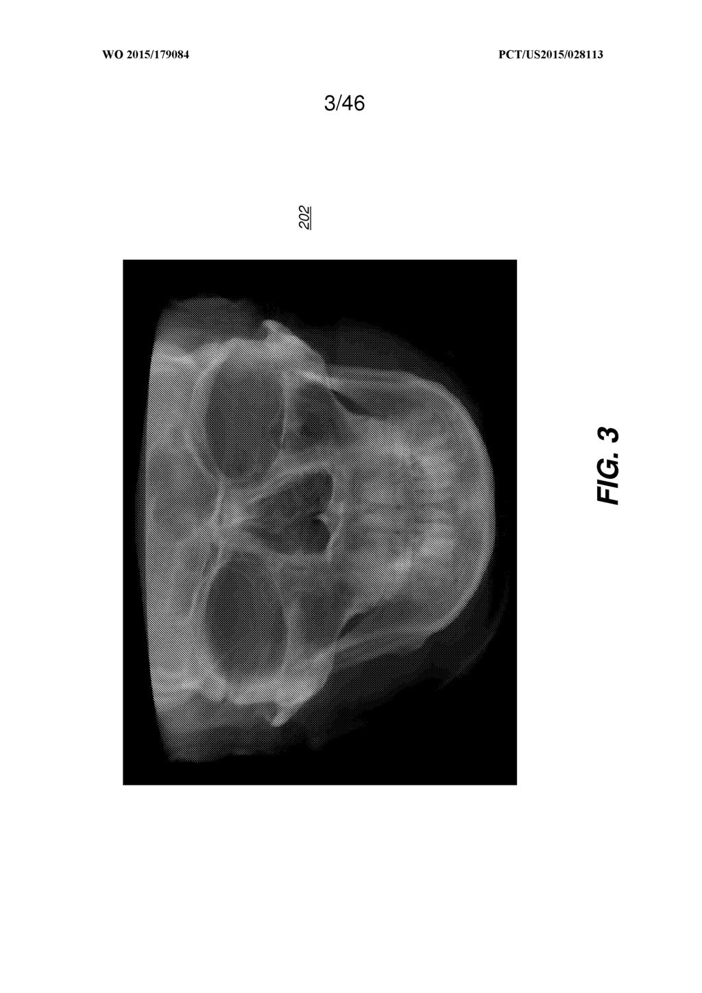
41
42
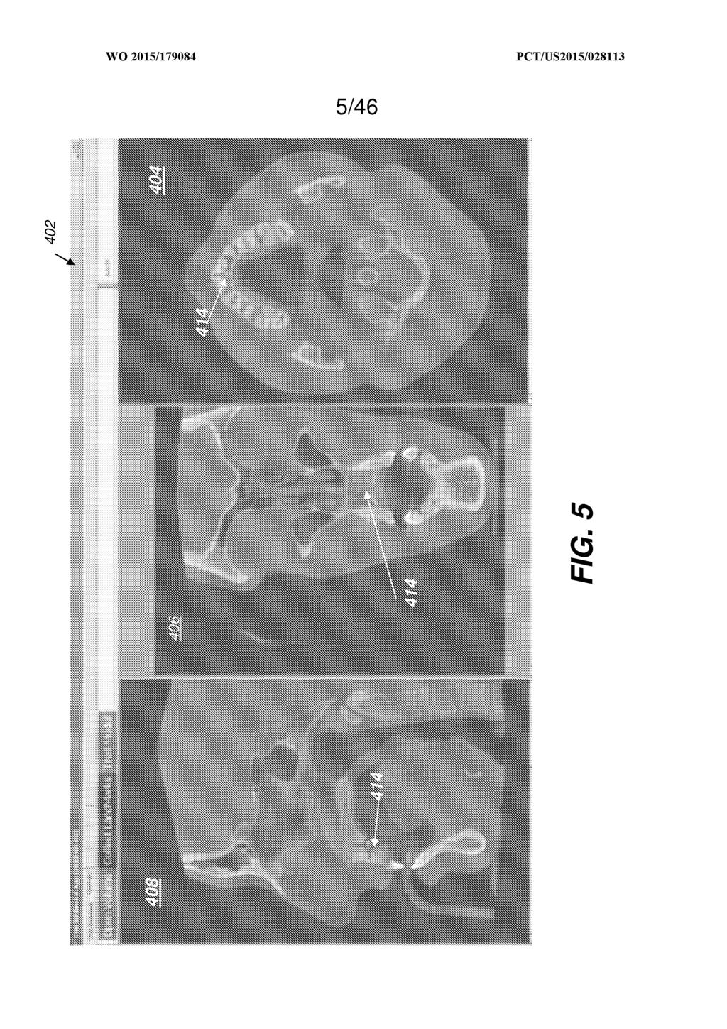
43
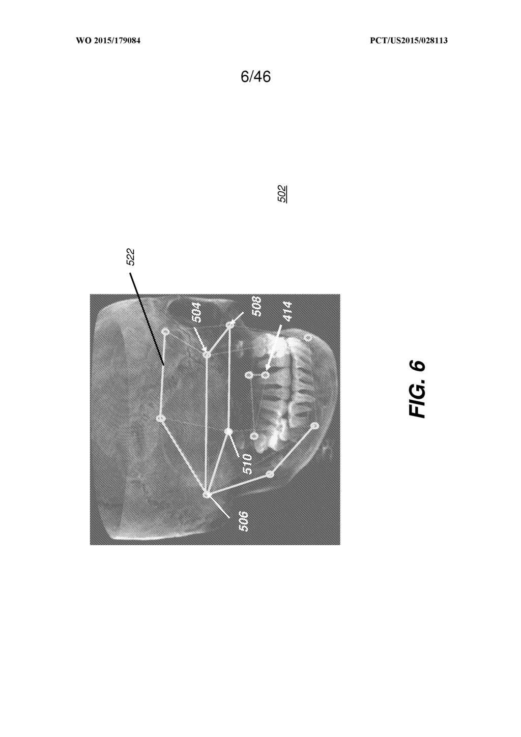
44
45
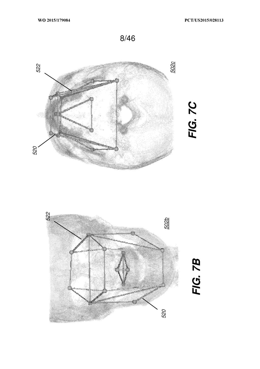
46
47
48
49
50
51
52
53
54
55
56
57
58
59
60
61
62
63
64
65
66
67
68
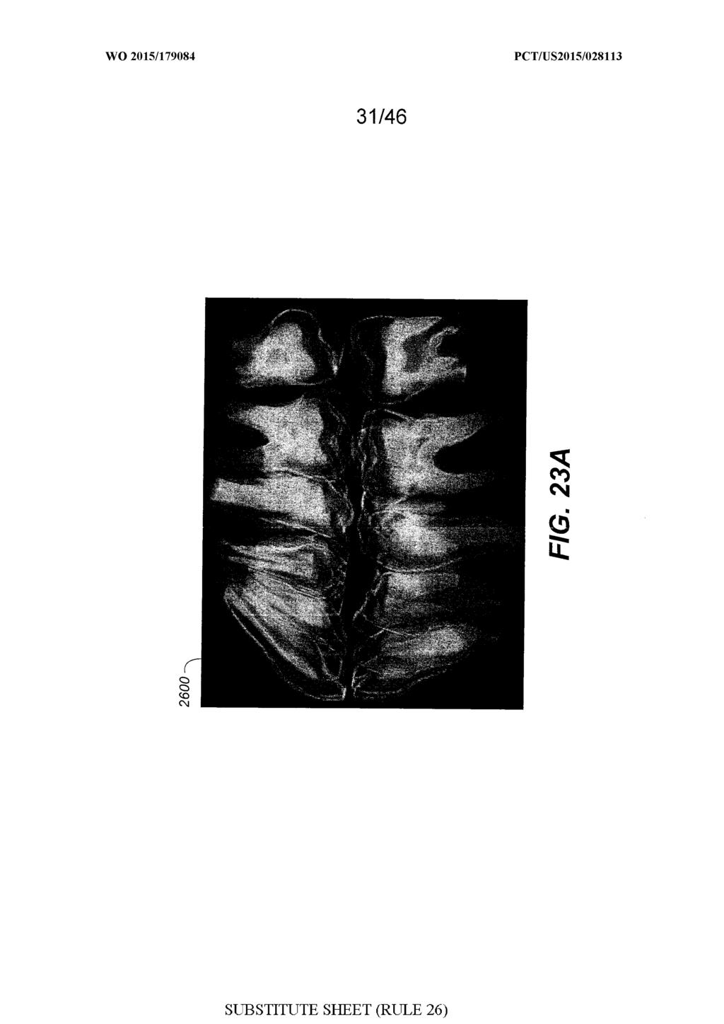
69
70
71
72
73
74
75
76
77
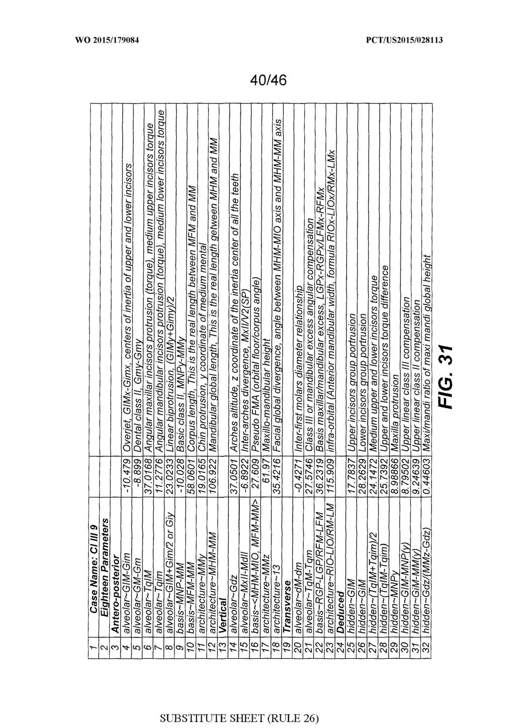
78
79
80
81
82
83
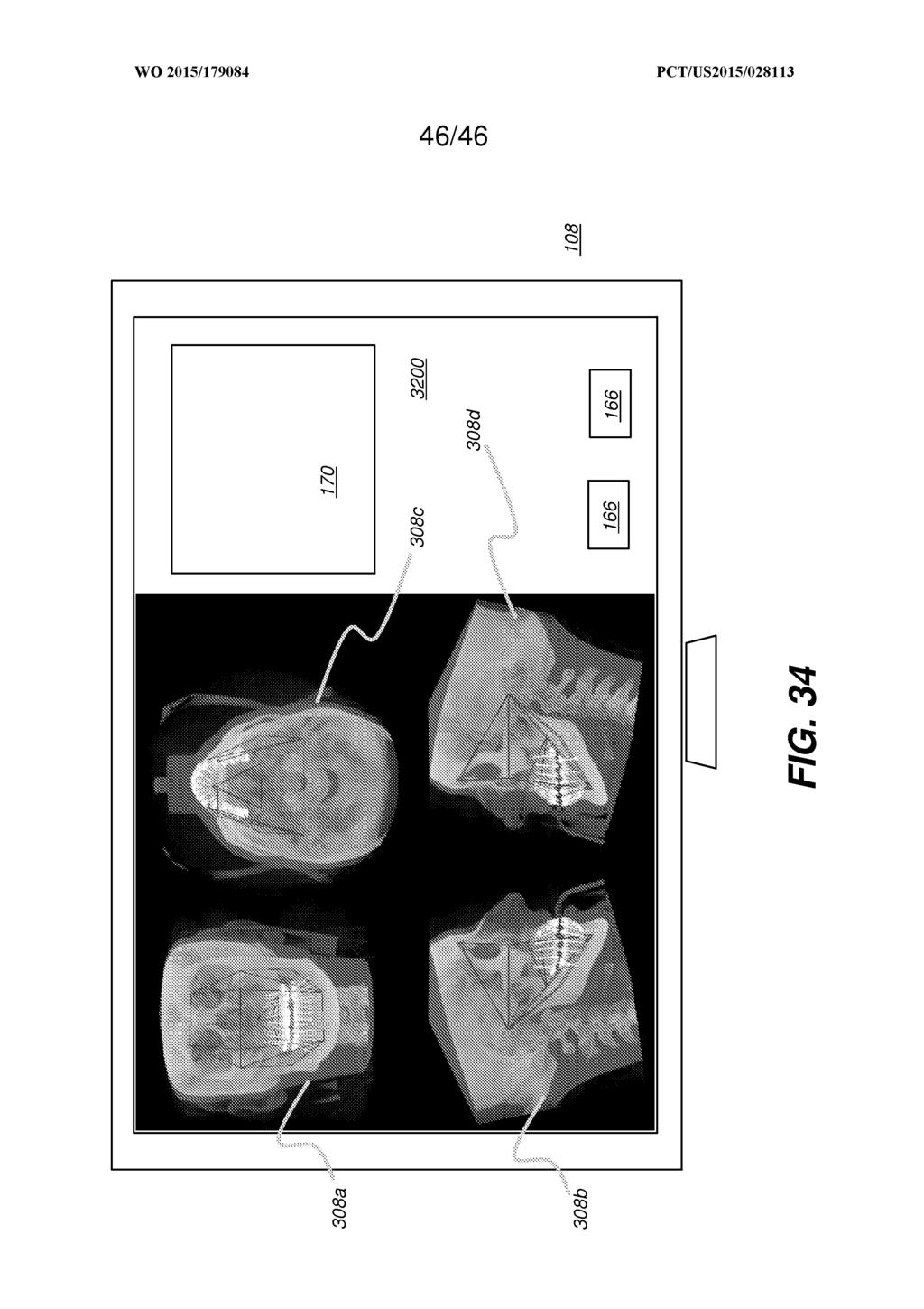
84
TMCH Report March February 2017
 TMCH Report March 2013 - February 2017 Contents Contents 2 1 Trademark Clearinghouse global reporting 3 1.1 Number of jurisdictions for which a trademark record has been submitted for 3 2 Trademark Clearinghouse
WO 2013/ Al. 17 January 2013 ( ) P O P C T
 P O P C T") (12) INTERNATIONAL APPLICATION PUBLISHED UNDER THE PATENT COOPERATION TREATY (PCT) (19) World Intellectual Property Organization International Bureau (10) International Publication Number (43) International
(12) INTERNATIONAL APPLICATION PUBLISHED UNDER THE PATENT COOPERATION TREATY (PCT) (19) World Intellectual Property Organization International Bureau (10) International Publication Number (43) International
(12) INTERNATIONAL APPLICATION PUBLISHED UNDER THE PATENT COOPERATION TREATY (PCT)
 INTERNATIONAL APPLICATION PUBLISHED UNDER THE PATENT COOPERATION TREATY (PCT)") (12) INTERNATIONAL APPLICATION PUBLISHED UNDER THE PATENT COOPERATION TREATY (PCT) (19) World Intellectual Property Organization International Bureau (43) International Publication Date (10) International
(12) INTERNATIONAL APPLICATION PUBLISHED UNDER THE PATENT COOPERATION TREATY (PCT) (19) World Intellectual Property Organization International Bureau (43) International Publication Date (10) International
WO 2017/ Al. 15 June 2017 ( )
") (12) INTERNATIONAL APPLICATION PUBLISHED UNDER THE PATENT COOPERATION TREATY (PCT) (19) World Intellectual Property Organization International Bureau (10) International Publication Number (43) International
(12) INTERNATIONAL APPLICATION PUBLISHED UNDER THE PATENT COOPERATION TREATY (PCT) (19) World Intellectual Property Organization International Bureau (10) International Publication Number (43) International
(43) International Publication Date n n / ft * 3 May 2012 ( ) U l / 5 A
 International Publication Date n n / ft * 3 May 2012 ( ) U l / 5 A") (12) INTERNATIONAL APPLICATION PUBLISHED UNDER THE PATENT COOPERATION TREATY (PCT) (19) World Intellectual Property Organization International Bureau (10) International Publication Number (43) International
(12) INTERNATIONAL APPLICATION PUBLISHED UNDER THE PATENT COOPERATION TREATY (PCT) (19) World Intellectual Property Organization International Bureau (10) International Publication Number (43) International
TM), European (AL, AT, BE, BG, CH, CY, CZ, DE, DK, W., Houston, Texas (US).
, European (AL, AT, BE, BG, CH, CY, CZ, DE, DK, W., Houston, Texas (US).") (12) INTERNATIONAL APPLICATION PUBLISHED UNDER THE PATENT COOPERATION TREATY (PCT) (19) World Intellectual Property Organization International Bureau (10) International Publication Number (43) International
(12) INTERNATIONAL APPLICATION PUBLISHED UNDER THE PATENT COOPERATION TREATY (PCT) (19) World Intellectual Property Organization International Bureau (10) International Publication Number (43) International
TEPZZ _968ZZA_T EP A1 (19) (11) EP A1 (12) EUROPEAN PATENT APPLICATION. (51) Int Cl.: G06K 7/10 ( )
 (11) EP A1 (12) EUROPEAN PATENT APPLICATION. (51) Int Cl.: G06K 7/10 ( )") (19) TEPZZ _968ZZA_T (11) EP 3 196 800 A1 (12) EUROPEAN PATENT APPLICATION (43) Date of publication: 26.07.17 Bulletin 17/ (1) Int Cl.: G06K 7/ (06.01) (21) Application number: 1719738.8 (22) Date of filing:
(19) TEPZZ _968ZZA_T (11) EP 3 196 800 A1 (12) EUROPEAN PATENT APPLICATION (43) Date of publication: 26.07.17 Bulletin 17/ (1) Int Cl.: G06K 7/ (06.01) (21) Application number: 1719738.8 (22) Date of filing:
icatvision Quick Reference
 icatvision Quick Reference Navigating the i-cat Interface This guide shows how to: View reconstructed images Use main features and tools to optimize an image. REMINDER Images are displayed as if you are
EP A1 (19) (11) EP A1 (12) EUROPEAN PATENT APPLICATION. (43) Date of publication: Bulletin 2012/34
 (11) EP A1 (12) EUROPEAN PATENT APPLICATION. (43) Date of publication: Bulletin 2012/34") (19) (12) EUROPEAN PATENT APPLICATION (11) EP 2 490 138 A1 (43) Date of publication: 22.08.2012 Bulletin 2012/34 (1) Int Cl.: G06F 17/30 (2006.01) (21) Application number: 1214420.9 (22) Date of filing:
(19) (12) EUROPEAN PATENT APPLICATION (11) EP 2 490 138 A1 (43) Date of publication: 22.08.2012 Bulletin 2012/34 (1) Int Cl.: G06F 17/30 (2006.01) (21) Application number: 1214420.9 (22) Date of filing:
DZ, EC, EE, EG, ES, FI, GB, GD, GE, GH, GM, GT, HN, HR, HU, ID, IL, IN, IS, KE, KG, KM, KN, KP, KR, TZ, UA, UG, US, UZ, VC, VN, ZA, ZM, ZW.
 (12) INTERNATIONAL APPLICATION PUBLISHED UNDER THE PATENT COOPERATION TREATY (PCT) (19) World Intellectual Property Organization International Bureau (43) International Publication Date (10) International
EP A1 (19) (11) EP A1 (12) EUROPEAN PATENT APPLICATION. (51) Int Cl.: G06T 15/60 ( )
 (11) EP A1 (12) EUROPEAN PATENT APPLICATION. (51) Int Cl.: G06T 15/60 ( )") (19) (12) EUROPEAN PATENT APPLICATION (11) EP 2 234 069 A1 (43) Date of publication: 29.09.2010 Bulletin 2010/39 (51) Int Cl.: G06T 15/60 (2006.01) (21) Application number: 09364002.7 (22) Date of filing:
(19) (12) EUROPEAN PATENT APPLICATION (11) EP 2 234 069 A1 (43) Date of publication: 29.09.2010 Bulletin 2010/39 (51) Int Cl.: G06T 15/60 (2006.01) (21) Application number: 09364002.7 (22) Date of filing:
TEPZZ 6Z8446A_T EP A1 (19) (11) EP A1 (12) EUROPEAN PATENT APPLICATION. (51) Int Cl.: H04L 9/08 ( ) H04L 9/32 (2006.
 (11) EP A1 (12) EUROPEAN PATENT APPLICATION. (51) Int Cl.: H04L 9/08 ( ) H04L 9/32 (2006.") (19) TEPZZ 6Z8446A_T (11) EP 2 608 446 A1 (12) EUROPEAN PATENT APPLICATION (43) Date of publication: 26.06.2013 Bulletin 2013/26 (1) Int Cl.: H04L 9/08 (2006.01) H04L 9/32 (2006.01) (21) Application number:
(19) TEPZZ 6Z8446A_T (11) EP 2 608 446 A1 (12) EUROPEAN PATENT APPLICATION (43) Date of publication: 26.06.2013 Bulletin 2013/26 (1) Int Cl.: H04L 9/08 (2006.01) H04L 9/32 (2006.01) (21) Application number:
(43) International Publication Date WO 2013/ Al 4 April 2013 ( ) W P O P C T
 International Publication Date WO 2013/ Al 4 April 2013 ( ) W P O P C T") (12) INTERNATIONAL APPLICATION PUBLISHED UNDER THE PATENT COOPERATION TREATY (PCT) (19) World Intellectual Property Organization International Bureau (10) International Publication Number (43) International
(12) INTERNATIONAL APPLICATION PUBLISHED UNDER THE PATENT COOPERATION TREATY (PCT) (19) World Intellectual Property Organization International Bureau (10) International Publication Number (43) International
(51) Int Cl.: H04L 12/24 ( ) WU, Qin
 Int Cl.: H04L 12/24 ( ) WU, Qin") (19) TEPZZ Z 68A_T (11) EP 3 3 68 A1 (12) EUROPEAN PATENT APPLICATION published in accordance with Art. 13(4) EPC (43) Date of publication: 09.08.17 Bulletin 17/32 (21) Application number: 182297.9 (22)
(19) TEPZZ Z 68A_T (11) EP 3 3 68 A1 (12) EUROPEAN PATENT APPLICATION published in accordance with Art. 13(4) EPC (43) Date of publication: 09.08.17 Bulletin 17/32 (21) Application number: 182297.9 (22)
(12) INTERNATIONAL APPLICATION PUBLISHED UNDER THE PATENT COOPERATION TREATY (PCT) (19) World Intellectual Property Organization International Bureau
 INTERNATIONAL APPLICATION PUBLISHED UNDER THE PATENT COOPERATION TREATY (PCT) (19) World Intellectual Property Organization International Bureau") (12) INTERNATIONAL APPLICATION PUBLISHED UNDER THE PATENT COOPERATION TREATY (PCT) (19) World Intellectual Property Organization International Bureau (10) International Publication Number (43) International
(12) INTERNATIONAL APPLICATION PUBLISHED UNDER THE PATENT COOPERATION TREATY (PCT) (19) World Intellectual Property Organization International Bureau (10) International Publication Number (43) International
EP A1 (19) (11) EP A1. (12) EUROPEAN PATENT APPLICATION published in accordance with Art. 153(4) EPC
 (11) EP A1. (12) EUROPEAN PATENT APPLICATION published in accordance with Art. 153(4) EPC") (19) (12) EUROPEAN PATENT APPLICATION published in accordance with Art. 153(4) EPC (11) EP 2 493 239 A1 (43) Date of publication: 29.08.2012 Bulletin 2012/35 (21) Application number: 10829523.9 (22) Date
(19) (12) EUROPEAN PATENT APPLICATION published in accordance with Art. 153(4) EPC (11) EP 2 493 239 A1 (43) Date of publication: 29.08.2012 Bulletin 2012/35 (21) Application number: 10829523.9 (22) Date
TEPZZ 85 9Z_A_T EP A1 (19) (11) EP A1 (12) EUROPEAN PATENT APPLICATION
 (11) EP A1 (12) EUROPEAN PATENT APPLICATION") (19) TEPZZ 8 9Z_A_T (11) EP 2 83 901 A1 (12) EUROPEAN PATENT APPLICATION (43) Date of publication: 01.04.1 Bulletin 1/14 (21) Application number: 141861.1 (1) Int Cl.: G01P 21/00 (06.01) G01C 2/00 (06.01)
(19) TEPZZ 8 9Z_A_T (11) EP 2 83 901 A1 (12) EUROPEAN PATENT APPLICATION (43) Date of publication: 01.04.1 Bulletin 1/14 (21) Application number: 141861.1 (1) Int Cl.: G01P 21/00 (06.01) G01C 2/00 (06.01)
TEPZZ 8_8997A_T EP A1 (19) (11) EP A1 (12) EUROPEAN PATENT APPLICATION
 (11) EP A1 (12) EUROPEAN PATENT APPLICATION") (19) TEPZZ 8_8997A_T (11) EP 2 818 997 A1 (12) EUROPEAN PATENT APPLICATION (43) Date of publication: 31.12.2014 Bulletin 2015/01 (21) Application number: 13174439.3 (51) Int Cl.: G06F 3/0488 (2013.01)
(19) TEPZZ 8_8997A_T (11) EP 2 818 997 A1 (12) EUROPEAN PATENT APPLICATION (43) Date of publication: 31.12.2014 Bulletin 2015/01 (21) Application number: 13174439.3 (51) Int Cl.: G06F 3/0488 (2013.01)
TEPZZ 8864Z9A_T EP A1 (19) (11) EP A1 (12) EUROPEAN PATENT APPLICATION. (51) Int Cl.: B60W 30/14 ( ) B60W 50/00 (2006.
 (11) EP A1 (12) EUROPEAN PATENT APPLICATION. (51) Int Cl.: B60W 30/14 ( ) B60W 50/00 (2006.") (19) TEPZZ 8864Z9A_T (11) EP 2 886 9 A1 (12) EUROPEAN PATENT APPLICATION (43) Date of publication: 24.06. Bulletin /26 (1) Int Cl.: B60W /14 (06.01) B60W 0/00 (06.01) (21) Application number: 106043.7
(19) TEPZZ 8864Z9A_T (11) EP 2 886 9 A1 (12) EUROPEAN PATENT APPLICATION (43) Date of publication: 24.06. Bulletin /26 (1) Int Cl.: B60W /14 (06.01) B60W 0/00 (06.01) (21) Application number: 106043.7
TEPZZ Z7999A_T EP A1 (19) (11) EP A1 (12) EUROPEAN PATENT APPLICATION. (51) Int Cl.: B05B 15/04 ( )
 (11) EP A1 (12) EUROPEAN PATENT APPLICATION. (51) Int Cl.: B05B 15/04 ( )") (19) TEPZZ Z7999A_T (11) EP 3 7 999 A1 (12) EUROPEAN PATENT APPLICATION (43) Date of publication: 23.08.17 Bulletin 17/34 (1) Int Cl.: B0B 1/04 (06.01) (21) Application number: 1617686.1 (22) Date of filing:
(19) TEPZZ Z7999A_T (11) EP 3 7 999 A1 (12) EUROPEAN PATENT APPLICATION (43) Date of publication: 23.08.17 Bulletin 17/34 (1) Int Cl.: B0B 1/04 (06.01) (21) Application number: 1617686.1 (22) Date of filing:
(12) INTERNATIONAL APPLICATION PUBLISHED UNDER THE PATENT COOPERATION TREATY (PCT)
 INTERNATIONAL APPLICATION PUBLISHED UNDER THE PATENT COOPERATION TREATY (PCT)") (12) INTERNATIONAL APPLICATION PUBLISHED UNDER THE PATENT COOPERATION TREATY (PCT) (19) World Intellectual Property Organization International Bureau (43) International Publication Date (10) International
(12) INTERNATIONAL APPLICATION PUBLISHED UNDER THE PATENT COOPERATION TREATY (PCT) (19) World Intellectual Property Organization International Bureau (43) International Publication Date (10) International
TEPZZ 98 _55A_T EP A1 (19) (11) EP A1 (12) EUROPEAN PATENT APPLICATION
 (11) EP A1 (12) EUROPEAN PATENT APPLICATION") (19) TEPZZ 98 _A_T (11) EP 2 983 1 A1 (12) EUROPEAN PATENT APPLICATION (43) Date of publication:.02.16 Bulletin 16/06 (21) Application number: 1180049.7 (1) Int Cl.: G08G /06 (06.01) G08G 7/00 (06.01)
(19) TEPZZ 98 _A_T (11) EP 2 983 1 A1 (12) EUROPEAN PATENT APPLICATION (43) Date of publication:.02.16 Bulletin 16/06 (21) Application number: 1180049.7 (1) Int Cl.: G08G /06 (06.01) G08G 7/00 (06.01)
TEPZZ 6 8A_T EP A1 (19) (11) EP A1 (12) EUROPEAN PATENT APPLICATION
 (11) EP A1 (12) EUROPEAN PATENT APPLICATION") (19) TEPZZ 6 8A_T (11) EP 3 121 638 A1 (12) EUROPEAN PATENT APPLICATION (43) Date of publication: 2.01.17 Bulletin 17/04 (21) Application number: 1380032.1 (1) Int Cl.: G02B 27/01 (06.01) G06F 11/16 (06.01)
(19) TEPZZ 6 8A_T (11) EP 3 121 638 A1 (12) EUROPEAN PATENT APPLICATION (43) Date of publication: 2.01.17 Bulletin 17/04 (21) Application number: 1380032.1 (1) Int Cl.: G02B 27/01 (06.01) G06F 11/16 (06.01)
Figure 1. (43) International Publication Date WO 2015/ Al 9 July 2015 ( ) W P O P C T. [Continued on nextpage]
![Figure 1. (43) International Publication Date WO 2015/ Al 9 July 2015 ( ) W P O P C T. [Continued on nextpage]](/thumbs/93/113817277.jpg "Figure 1. (43) International Publication Date WO 2015/ Al 9 July 2015 ( ) W P O P C T. [Continued on nextpage]") (12) INTERNATIONAL APPLICATION PUBLISHED UNDER THE PATENT COOPERATION TREATY (PCT) (19) World Intellectual Property Organization International Bureau (10) International Publication Number (43) International
(12) INTERNATIONAL APPLICATION PUBLISHED UNDER THE PATENT COOPERATION TREATY (PCT) (19) World Intellectual Property Organization International Bureau (10) International Publication Number (43) International
(51) Int Cl.: H04L 29/06 ( )
 Int Cl.: H04L 29/06 ( )") (19) TEPZZ 94Z96B_T (11) EP 2 9 96 B1 (12) EUROPEAN PATENT SPECIFICATION (4) Date of publication and mention of the grant of the patent: 26.04.17 Bulletin 17/17 (1) Int Cl.: H04L 29/06 (06.01) (21) Application
(19) TEPZZ 94Z96B_T (11) EP 2 9 96 B1 (12) EUROPEAN PATENT SPECIFICATION (4) Date of publication and mention of the grant of the patent: 26.04.17 Bulletin 17/17 (1) Int Cl.: H04L 29/06 (06.01) (21) Application
PCT WO 2007/ Al
 (12) INTERNATIONAL APPLICATION PUBLISHED UNDER THE PATENT COOPERATION TREATY (PCT) (19) World Intellectual Property Organization International Bureau (43) International Publication Date (10) International
TEPZZ Z47A_T EP A1 (19) (11) EP A1 (12) EUROPEAN PATENT APPLICATION. (51) Int Cl.: G06Q 30/00 ( )
 (11) EP A1 (12) EUROPEAN PATENT APPLICATION. (51) Int Cl.: G06Q 30/00 ( )") (19) TEPZZ _ _Z47A_T (11) EP 3 131 047 A1 (12) EUROPEAN PATENT APPLICATION (43) Date of publication: 1.02.17 Bulletin 17/07 (1) Int Cl.: G06Q /00 (12.01) (21) Application number: 160297.4 (22) Date of
(19) TEPZZ _ _Z47A_T (11) EP 3 131 047 A1 (12) EUROPEAN PATENT APPLICATION (43) Date of publication: 1.02.17 Bulletin 17/07 (1) Int Cl.: G06Q /00 (12.01) (21) Application number: 160297.4 (22) Date of
Shadow casting. What is the problem? Cone Beam Computed Tomography THE OBJECTIVES OF DIAGNOSTIC IMAGING IDEAL DIAGNOSTIC IMAGING STUDY LIMITATIONS
 Cone Beam Computed Tomography THE OBJECTIVES OF DIAGNOSTIC IMAGING Reveal pathology Reveal the anatomic truth Steven R. Singer, DDS srs2@columbia.edu IDEAL DIAGNOSTIC IMAGING STUDY Provides desired diagnostic
WO 2013/ Al. 11 April 2013 ( ) P O P C T
 P O P C T") (12) INTERNATIONAL APPLICATION PUBLISHED UNDER THE PATENT COOPERATION TREATY (PCT) (19) World Intellectual Property Organization International Bureau (10) International Publication Number (43) International
(12) INTERNATIONAL APPLICATION PUBLISHED UNDER THE PATENT COOPERATION TREATY (PCT) (19) World Intellectual Property Organization International Bureau (10) International Publication Number (43) International
10 December 2009 ( ) WO 2009/ A2
 WO 2009/ A2") (12) INTERNATIONAL APPLICATION PUBLISHED UNDER THE PATENT COOPERATION TREATY (PCT) (19) World Intellectual Property Organization International Bureau (43) International Publication Date (10) International
(12) INTERNATIONAL APPLICATION PUBLISHED UNDER THE PATENT COOPERATION TREATY (PCT) (19) World Intellectual Property Organization International Bureau (43) International Publication Date (10) International
PLANMECA PROMAX 3D MID CBCT UNIT
 1(5) PLANMECA PROMAX 3D MID CBCT UNIT Introduction The Planmeca ProMax 3D Mid X-ray unit uses cone beam computerized tomography (CBCT) to produce three-dimensional X-ray images. Panoramic and cephalometric
GM, KE, LR, LS, MW, MZ, NA, RW, SD, SL, SZ, TZ, fornia (US).
.") (12) INTERNATIONAL APPLICATION PUBLISHED UNDER THE PATENT COOPERATION TREATY (PCT) (19) World Intellectual Property Organization International Bureau (10) International Publication Number (43) International
(12) INTERNATIONAL APPLICATION PUBLISHED UNDER THE PATENT COOPERATION TREATY (PCT) (19) World Intellectual Property Organization International Bureau (10) International Publication Number (43) International
DNSSEC Workshop. Dan York, Internet Society ICANN 53 June 2015
 DNSSEC Workshop Dan York, Internet Society ICANN 53 June 2015 First, a word about our host... 2 Program Committee Steve Crocker, Shinkuro, Inc. Mark Elkins, DNS/ZACR Cath Goulding, Nominet Jean Robert
(12) Patent Application Publication (10) Pub. No.: US 2011/ A1
 Patent Application Publication (10) Pub. No.: US 2011/ A1") (19) United States US 2011 0255765A1 (12) Patent Application Publication (10) Pub. No.: US 2011/0255765 A1 Carlson et al. (43) Pub. Date: Oct. 20, 2011 (54) REDUCTION AND REMOVAL OF ARTIFACTS FROMA THREE-DIMIENSIONAL
(19) United States US 2011 0255765A1 (12) Patent Application Publication (10) Pub. No.: US 2011/0255765 A1 Carlson et al. (43) Pub. Date: Oct. 20, 2011 (54) REDUCTION AND REMOVAL OF ARTIFACTS FROMA THREE-DIMIENSIONAL
Lionbridge ondemand for Adobe Experience Manager
 Lionbridge ondemand for Adobe Experience Manager Version 1.1.0 Configuration Guide October 24, 2017 Copyright Copyright 2017 Lionbridge Technologies, Inc. All rights reserved. Published in the USA. March,
A Study of Medical Image Analysis System
 Indian Journal of Science and Technology, Vol 8(25), DOI: 10.17485/ijst/2015/v8i25/80492, October 2015 ISSN (Print) : 0974-6846 ISSN (Online) : 0974-5645 A Study of Medical Image Analysis System Kim Tae-Eun
INTRODUCTION TO MEDICAL IMAGING- 3D LOCALIZATION LAB MANUAL 1. Modifications for P551 Fall 2013 Medical Physics Laboratory
 INTRODUCTION TO MEDICAL IMAGING- 3D LOCALIZATION LAB MANUAL 1 Modifications for P551 Fall 2013 Medical Physics Laboratory Introduction Following the introductory lab 0, this lab exercise the student through
EP A1 (19) (11) EP A1. (12) EUROPEAN PATENT APPLICATION published in accordance with Art. 153(4) EPC
 (11) EP A1. (12) EUROPEAN PATENT APPLICATION published in accordance with Art. 153(4) EPC") (19) (12) EUROPEAN PATENT APPLICATION published in accordance with Art. 13(4) EPC (11) EP 2 482 24 A1 (43) Date of publication: 01.08.2012 Bulletin 2012/31 (21) Application number: 818282. (22) Date of
(19) (12) EUROPEAN PATENT APPLICATION published in accordance with Art. 13(4) EPC (11) EP 2 482 24 A1 (43) Date of publication: 01.08.2012 Bulletin 2012/31 (21) Application number: 818282. (22) Date of
Planmeca ProMax 3D s CBCT unit
 D0010759 1(5) Planmeca ProMax 3D s CBCT unit Introduction The Planmeca ProMax 3D s X-ray unit uses cone beam computerized tomography (CBCT) to produce threedimensional X-ray images. Panoramic and cephalometric
MAWA Forum State of Play. Cooperation Planning & Support Henk Corporaal MAWA Forum Chair
 MAWA Forum State of Play Cooperation Planning & Support Henk Corporaal MAWA Forum Chair Content Background MAWA Initiative Achievements and Status to date Future Outlook 2 Background MAWA Initiative The
30 June 2011 ( ) W / / / / A
 W / / / / A") (12) INTERNATIONAL APPLICATION PUBLISHED UNDER THE PATENT COOPERATION TREATY (PCT) (19) World Intellectual Property Organization International Bureau (10) International Publication Number (43) International
(12) INTERNATIONAL APPLICATION PUBLISHED UNDER THE PATENT COOPERATION TREATY (PCT) (19) World Intellectual Property Organization International Bureau (10) International Publication Number (43) International
(12) INTERNATIONAL APPLICATION PUBLISHED UNDER THE PATENT COOPERATION TREATY (PCT)
 INTERNATIONAL APPLICATION PUBLISHED UNDER THE PATENT COOPERATION TREATY (PCT)") (12) INTERNATIONAL APPLICATION PUBLISHED UNDER THE PATENT COOPERATION TREATY (PCT) (19) World Intellectual Property Organization International Bureau 1111111111111111 111111 111111111111111 111 111 11111111111111111111
(12) INTERNATIONAL APPLICATION PUBLISHED UNDER THE PATENT COOPERATION TREATY (PCT) (19) World Intellectual Property Organization International Bureau 1111111111111111 111111 111111111111111 111 111 11111111111111111111
TEPZZ 74_475A_T EP A1 (19) (11) EP A1 (12) EUROPEAN PATENT APPLICATION. (51) Int Cl.: H04L 29/12 ( )
 (11) EP A1 (12) EUROPEAN PATENT APPLICATION. (51) Int Cl.: H04L 29/12 ( )") (19) TEPZZ 74_47A_T (11) EP 2 741 47 A1 (12) EUROPEAN PATENT APPLICATION (43) Date of publication: 11.06.14 Bulletin 14/24 (1) Int Cl.: H04L 29/12 (06.01) (21) Application number: 131968.6 (22) Date of
(19) TEPZZ 74_47A_T (11) EP 2 741 47 A1 (12) EUROPEAN PATENT APPLICATION (43) Date of publication: 11.06.14 Bulletin 14/24 (1) Int Cl.: H04L 29/12 (06.01) (21) Application number: 131968.6 (22) Date of
(CN). PCT/CN20 14/ (81) Designated States (unless otherwise indicated, for every kind of national protection available): AE, AG, AL, AM,
. PCT/CN20 14/ (81) Designated States (unless otherwise indicated, for every kind of national protection available): AE, AG, AL, AM,") (12) INTERNATIONAL APPLICATION PUBLISHED UNDER THE PATENT COOPERATION TREATY (PCT) (19) World Intellectual Property Organization International Bureau (10) International Publication Number (43) International
(12) INTERNATIONAL APPLICATION PUBLISHED UNDER THE PATENT COOPERATION TREATY (PCT) (19) World Intellectual Property Organization International Bureau (10) International Publication Number (43) International
One Machine... Mac OS Compatible! Multiple Modalities. ProMax 3D & 3D s
 One Machine... Multiple Modalities Mac OS Compatible! 3D Bitewing Panoramic Cephalometric Features Availability of multiple imaging modalities in one machine (3D, bitewing, panoramic, and cephalometric)
ica) Inc., 2355 Dulles Corner Boulevard, 7th Floor, before the expiration of the time limit for amending the
 Inc., 2355 Dulles Corner Boulevard, 7th Floor, before the expiration of the time limit for amending the") (12) INTERNATIONAL APPLICATION PUBLISHED UNDER THE PATENT COOPERATION TREATY (PCT) (19) World Intellectual Property Organization International Bureau (10) International Publication Number (43) International
(12) INTERNATIONAL APPLICATION PUBLISHED UNDER THE PATENT COOPERATION TREATY (PCT) (19) World Intellectual Property Organization International Bureau (10) International Publication Number (43) International
Planmeca ProMax 3D Max CBCT unit
 D00107623 1(6) Planmeca ProMax 3D Max CBCT unit Introduction The Planmeca ProMax 3D Max X-ray unit uses cone beam computerized tomography (CBCT) to produce threedimensional X-ray images. Panoramic and
EP A1 (19) (11) EP A1 (12) EUROPEAN PATENT APPLICATION. (51) Int Cl.: H04L 12/56 ( )
 (11) EP A1 (12) EUROPEAN PATENT APPLICATION. (51) Int Cl.: H04L 12/56 ( )") (19) (12) EUROPEAN PATENT APPLICATION (11) EP 1 760 963 A1 (43) Date of publication: 07.03.07 Bulletin 07/ (1) Int Cl.: H04L 12/6 (06.01) (21) Application number: 06018260.7 (22) Date of filing: 31.08.06
(19) (12) EUROPEAN PATENT APPLICATION (11) EP 1 760 963 A1 (43) Date of publication: 07.03.07 Bulletin 07/ (1) Int Cl.: H04L 12/6 (06.01) (21) Application number: 06018260.7 (22) Date of filing: 31.08.06
2016 Survey of Internet Carrier Interconnection Agreements
 2016 Survey of Internet Carrier Interconnection Agreements Bill Woodcock Marco Frigino Packet Clearing House November 21, 2016 PCH Peering Survey 2011 Five years ago, PCH conducted the first-ever broad
*EP A2* EP A2 (19) (11) EP A2 (12) EUROPEAN PATENT APPLICATION. (43) Date of publication: Bulletin 2005/37
 (11) EP A2 (12) EUROPEAN PATENT APPLICATION. (43) Date of publication: Bulletin 2005/37") (19) Europäisches Patentamt European Patent Office Office européen des brevets *EP007312A2* (11) EP 1 7 312 A2 (12) EUROPEAN PATENT APPLICATION (43) Date of publication: 14.09.0 Bulletin 0/37 (1) Int Cl.
(19) Europäisches Patentamt European Patent Office Office européen des brevets *EP007312A2* (11) EP 1 7 312 A2 (12) EUROPEAN PATENT APPLICATION (43) Date of publication: 14.09.0 Bulletin 0/37 (1) Int Cl.
FILE SYSTEM 102 DIRECTORY MODULE 104 SELECTION MODULE. Fig. 1
 (12) INTERNATIONAL APPLICATION PUBLISHED UNDER THE PATENT COOPERATION TREATY (PCT) (19) World Intellectual Property Organization International Bureau (10) International Publication Number (43) International
icatvision Software Manual
 University of Minnesota School of Dentistry icatvision Software Manual April 19, 2013 Mansur Ahmad, BDS, PhD Associate Professor, University of Minnesota School of Dentistry Director, American Board of
I International Bureau (10) International Publication Number (43) International Publication Date
 International Publication Number (43) International Publication Date") (12) INTERNATIONAL APPLICATION PUBLISHED UNDER THE PATENT COOPERATION TREATY (PCT) (19) World Intellectual Property Organization I International Bureau (10) International Publication Number (43) International
(12) INTERNATIONAL APPLICATION PUBLISHED UNDER THE PATENT COOPERATION TREATY (PCT) (19) World Intellectual Property Organization I International Bureau (10) International Publication Number (43) International
Dolphin 3D Imaging 11.7 beta
 Dolphin 3D Imaging 11.7 beta The Dolphin 3D software module is a powerful tool that makes processing 3D data extremely simple, enabling dental specialists from a wide variety of disciplines to diagnose,
(51) Int Cl.: G06F 21/00 ( ) G11B 20/00 ( ) G06Q 10/00 ( )
 Int Cl.: G06F 21/00 ( ) G11B 20/00 ( ) G06Q 10/00 ( )") (19) Europäisches Patentamt European Patent Office Office européen des brevets (12) EUROPEAN PATENT APPLICATION (11) EP 1 724 699 A1 (43) Date of publication: 22.11.2006 Bulletin 2006/47 (21) Application
(19) Europäisches Patentamt European Patent Office Office européen des brevets (12) EUROPEAN PATENT APPLICATION (11) EP 1 724 699 A1 (43) Date of publication: 22.11.2006 Bulletin 2006/47 (21) Application
STATEMENT REGARDING FEDERALLY SPONSORED RESEARCH OR THE NAMES OF THE PARTIES TO A JOINT RESEARCH AGREEMENT.
 TITLE OF INVENTION. A distance measuring device using a method of spanning separately targeted endpoints. This application claims the benefit of U.S. Provisional Application No. 61/477,511, filed April
TEPZZ 78779ZB_T EP B1 (19) (11) EP B1 (12) EUROPEAN PATENT SPECIFICATION
 (11) EP B1 (12) EUROPEAN PATENT SPECIFICATION") (19) TEPZZ 78779ZB_T (11) EP 2 787 790 B1 (12) EUROPEAN PATENT SPECIFICATION (4) Date of publication and mention of the grant of the patent: 26.07.17 Bulletin 17/ (21) Application number: 12878644.9 (22)
(19) TEPZZ 78779ZB_T (11) EP 2 787 790 B1 (12) EUROPEAN PATENT SPECIFICATION (4) Date of publication and mention of the grant of the patent: 26.07.17 Bulletin 17/ (21) Application number: 12878644.9 (22)
WO 2008/ Al PCT. (19) World Intellectual Property Organization International Bureau
 World Intellectual Property Organization International Bureau") (12) INTERNATIONAL APPLICATION PUBLISHED UNDER THE PATENT COOPERATION TREATY (PCT) (19) World Intellectual Property Organization International Bureau (43) International Publication Date (10) International
(12) INTERNATIONAL APPLICATION PUBLISHED UNDER THE PATENT COOPERATION TREATY (PCT) (19) World Intellectual Property Organization International Bureau (43) International Publication Date (10) International
Tracking Handle Menu Lloyd K. Konneker Jan. 29, Abstract
 Tracking Handle Menu Lloyd K. Konneker Jan. 29, 2011 Abstract A contextual pop-up menu of commands is displayed by an application when a user moves a pointer near an edge of an operand object. The menu
Computational Medical Imaging Analysis Chapter 4: Image Visualization
 Computational Medical Imaging Analysis Chapter 4: Image Visualization Jun Zhang Laboratory for Computational Medical Imaging & Data Analysis Department of Computer Science University of Kentucky Lexington,
Image Acquisition Systems
 Image Acquisition Systems Goals and Terminology Conventional Radiography Axial Tomography Computer Axial Tomography (CAT) Magnetic Resonance Imaging (MRI) PET, SPECT Ultrasound Microscopy Imaging ITCS
(12) INTERNATIONAL APPLICATION PUBLISHED UNDER THE PATENT COOPERATION TREATY (PCT)
 INTERNATIONAL APPLICATION PUBLISHED UNDER THE PATENT COOPERATION TREATY (PCT)") (12) INTERNATIONAL APPLICATION PUBLISHED UNDER THE PATENT COOPERATION TREATY (PCT) (19) World Intellectual Property Organization International Bureau (10) International Publication Number (43) International
(12) INTERNATIONAL APPLICATION PUBLISHED UNDER THE PATENT COOPERATION TREATY (PCT) (19) World Intellectual Property Organization International Bureau (10) International Publication Number (43) International
(12) INTERNATIONAL APPLICATION PUBLISHED UNDER THE PATENT COOPERATION TREATY (PCT)
 INTERNATIONAL APPLICATION PUBLISHED UNDER THE PATENT COOPERATION TREATY (PCT)") (12) INTERNATIONAL APPLICATION PUBLISHED UNDER THE PATENT COOPERATION TREATY (PCT) (l J w;~:s~:!~:::.:opcrty ~ llllllllllll~~~~~~~~;~~~~~~~~~~~~~~~~.~~~~~!~~~~~llllllllll (43) International Publication
(12) INTERNATIONAL APPLICATION PUBLISHED UNDER THE PATENT COOPERATION TREATY (PCT) (l J w;~:s~:!~:::.:opcrty ~ llllllllllll~~~~~~~~;~~~~~~~~~~~~~~~~.~~~~~!~~~~~llllllllll (43) International Publication
EP A1 (19) (11) EP A1 (12) EUROPEAN PATENT APPLICATION. (51) Int Cl.: G06F 17/30 ( )
 (11) EP A1 (12) EUROPEAN PATENT APPLICATION. (51) Int Cl.: G06F 17/30 ( )") (19) (12) EUROPEAN PATENT APPLICATION (11) EP 2 447 858 A1 (43) Date of publication: 02.05.2012 Bulletin 2012/18 (51) Int Cl.: G06F 17/30 (2006.01) (21) Application number: 11004965.7 (22) Date of filing:
(19) (12) EUROPEAN PATENT APPLICATION (11) EP 2 447 858 A1 (43) Date of publication: 02.05.2012 Bulletin 2012/18 (51) Int Cl.: G06F 17/30 (2006.01) (21) Application number: 11004965.7 (22) Date of filing:
TomoTherapy Related Projects. An image guidance alternative on Tomo Low dose MVCT reconstruction Patient Quality Assurance using Sinogram
 TomoTherapy Related Projects An image guidance alternative on Tomo Low dose MVCT reconstruction Patient Quality Assurance using Sinogram Development of A Novel Image Guidance Alternative for Patient Localization
EP A1 (19) (11) EP A1 (12) EUROPEAN PATENT APPLICATION. (43) Date of publication: Bulletin 2012/45
 (11) EP A1 (12) EUROPEAN PATENT APPLICATION. (43) Date of publication: Bulletin 2012/45") (19) (12) EUROPEAN PATENT APPLICATION (11) EP 2 521 319 A1 (43) Date of publication: 07.11.2012 Bulletin 2012/45 (51) Int Cl.: H04L 12/40 (2006.01) H04L 1/00 (2006.01) (21) Application number: 11164445.6
(19) (12) EUROPEAN PATENT APPLICATION (11) EP 2 521 319 A1 (43) Date of publication: 07.11.2012 Bulletin 2012/45 (51) Int Cl.: H04L 12/40 (2006.01) H04L 1/00 (2006.01) (21) Application number: 11164445.6
(12) INTERNATIONAL APPLICATION PUBLISHED UNDER THE PATENT COOPERATION TREATY (PCT)
 INTERNATIONAL APPLICATION PUBLISHED UNDER THE PATENT COOPERATION TREATY (PCT)") (12) INTERNATIONAL APPLICATION PUBLISHED UNDER THE PATENT COOPERATION TREATY (PCT) (19) World Intellectual Property Organization International Bureau (10) International Publication Number (43) International
(12) INTERNATIONAL APPLICATION PUBLISHED UNDER THE PATENT COOPERATION TREATY (PCT) (19) World Intellectual Property Organization International Bureau (10) International Publication Number (43) International
TEPZZ _Z_56ZA_T EP A1 (19) (11) EP A1 (12) EUROPEAN PATENT APPLICATION. (51) Int Cl.: G06F 17/30 ( )
 (11) EP A1 (12) EUROPEAN PATENT APPLICATION. (51) Int Cl.: G06F 17/30 ( )") (19) TEPZZ _Z_6ZA_T (11) EP 3 1 60 A1 (12) EUROPEAN PATENT APPLICATION (43) Date of publication: 07.12.16 Bulletin 16/49 (1) Int Cl.: G06F 17/ (06.01) (21) Application number: 16176.9 (22) Date of filing:
(19) TEPZZ _Z_6ZA_T (11) EP 3 1 60 A1 (12) EUROPEAN PATENT APPLICATION (43) Date of publication: 07.12.16 Bulletin 16/49 (1) Int Cl.: G06F 17/ (06.01) (21) Application number: 16176.9 (22) Date of filing:
(12) United States Patent (10) Patent No.: US 6,655,370 B1. Beckwith (45) Date of Patent: Dec. 2, 2003
 United States Patent (10) Patent No.: US 6,655,370 B1. Beckwith (45) Date of Patent: Dec. 2, 2003") USOO665537OB1 (12) United States Patent (10) Patent No.: US 6,655,370 B1 Beckwith (45) Date of Patent: Dec. 2, 2003 (54) FIRECRACKER LAUNCHING DEVICE 3,794,325 * 2/1974 Stender 4,995,371. A 2/1991 Kuizinas...
USOO665537OB1 (12) United States Patent (10) Patent No.: US 6,655,370 B1 Beckwith (45) Date of Patent: Dec. 2, 2003 (54) FIRECRACKER LAUNCHING DEVICE 3,794,325 * 2/1974 Stender 4,995,371. A 2/1991 Kuizinas...
Design and performance characteristics of a Cone Beam CT system for Leksell Gamma Knife Icon
 Design and performance characteristics of a Cone Beam CT system for Leksell Gamma Knife Icon WHITE PAPER Introduction Introducing an image guidance system based on Cone Beam CT (CBCT) and a mask immobilization
SMF Transient Voltage Suppressor Diode Series
 SMF Transient Voltage Suppressor Diode Series General Information The SMF series is designed specifically to protect sensitive electronic equipment from voltage transients induced by lightning and other
Profound understanding of anatomy
 ENGLISH Profound understanding of anatomy The unique Planmeca ProMax 3D product family offers equipment for all maxillofacial imaging. All volume sizes from the smallest special cases to whole head images
Tiops2005 user guide. Occlusograms from digital and analog pictures can be fitted to the cephalometric tracings.
 Tiops2005 user guide Contents Ib Leth Nielsen, DDS Division of Orthodontics University of California, San Francisco & Jens Bjørn-Jørgensen, DDS TIOPS ApS Roskilde, Denmark These guidelines are intended
TEPZZ _7655_A_T EP A1 (19) (11) EP A1 (12) EUROPEAN PATENT APPLICATION
 (11) EP A1 (12) EUROPEAN PATENT APPLICATION") (19) TEPZZ _76_A_T (11) EP 3 176 1 A1 (12) EUROPEAN PATENT APPLICATION (43) Date of publication: 07.06.2017 Bulletin 2017/23 (21) Application number: 1619703.0 (1) Int Cl.: G01J 1/42 (2006.01) G01J 1/02
(19) TEPZZ _76_A_T (11) EP 3 176 1 A1 (12) EUROPEAN PATENT APPLICATION (43) Date of publication: 07.06.2017 Bulletin 2017/23 (21) Application number: 1619703.0 (1) Int Cl.: G01J 1/42 (2006.01) G01J 1/02
WO 2016/ Al. 21 April 2016 ( ) P O P C T. Figure 2
 P O P C T. Figure 2") (12) INTERNATIONAL APPLICATION PUBLISHED UNDER THE PATENT COOPERATION TREATY (PCT) (19) World Intellectual Property Organization International Bureau (10) International Publication Number (43) International
(12) INTERNATIONAL APPLICATION PUBLISHED UNDER THE PATENT COOPERATION TREATY (PCT) (19) World Intellectual Property Organization International Bureau (10) International Publication Number (43) International
Acknowledgements. Atlas-based automatic measurements of the morphology of the tibiofemoral joint
 Atlas-based automatic measurements of the morphology of the tibiofemoral joint M Brehler 1, G Thawait 2, W Shyr 1, J Ramsay 3, JH Siewerdsen 1,2, W Zbijewski 1 1 Dept. of Biomedical Engineering, Johns
(12) Patent Application Publication (10) Pub. No.: US 2016/ A1
 Patent Application Publication (10) Pub. No.: US 2016/ A1") US 20160364902A1 (19) United States (12) Patent Application Publication (10) Pub. No.: US 2016/0364902 A1 Hong et al. (43) Pub. Date: (54) HIGH QUALITY EMBEDDED GRAPHICS (52) U.S. Cl. FOR REMOTE VISUALIZATION
US 20160364902A1 (19) United States (12) Patent Application Publication (10) Pub. No.: US 2016/0364902 A1 Hong et al. (43) Pub. Date: (54) HIGH QUALITY EMBEDDED GRAPHICS (52) U.S. Cl. FOR REMOTE VISUALIZATION
Visualisation : Lecture 1. So what is visualisation? Visualisation
 So what is visualisation? UG4 / M.Sc. Course 2006 toby.breckon@ed.ac.uk Computer Vision Lab. Institute for Perception, Action & Behaviour Introducing 1 Application of interactive 3D computer graphics to
eifu Trauma and Extremities
 Electronic Instructions for Use eifu Trauma and Extremities 1 Instructions for use of T&E products are available on the Stryker eifu website 2 Benefits Environmental aspect less paper, possible smaller
(12) United States Patent (10) Patent No.: US 8,253,777 B2
 United States Patent (10) Patent No.: US 8,253,777 B2") US008253777B2 (12) United States Patent (10) Patent No.: US 8,253,777 B2 Lin (45) Date of Patent: Aug. 28, 2012 (54) PANORAMIC CAMERA WITH A PLURALITY 7,424,218 B2 * 9/2008 Baudisch et al.... 396,322 OF
US008253777B2 (12) United States Patent (10) Patent No.: US 8,253,777 B2 Lin (45) Date of Patent: Aug. 28, 2012 (54) PANORAMIC CAMERA WITH A PLURALITY 7,424,218 B2 * 9/2008 Baudisch et al.... 396,322 OF
TEPZZ 99894ZA_T EP A1 (19) (11) EP A1 (12) EUROPEAN PATENT APPLICATION
 (11) EP A1 (12) EUROPEAN PATENT APPLICATION") (19) TEPZZ 99894ZA_T (11) EP 2 998 9 A1 (12) EUROPEAN PATENT APPLICATION (43) Date of publication: 23.03.16 Bulletin 16/12 (21) Application number: 18973.3 (1) Int Cl.: G07C 9/00 (06.01) B62H /00 (06.01)
(19) TEPZZ 99894ZA_T (11) EP 2 998 9 A1 (12) EUROPEAN PATENT APPLICATION (43) Date of publication: 23.03.16 Bulletin 16/12 (21) Application number: 18973.3 (1) Int Cl.: G07C 9/00 (06.01) B62H /00 (06.01)
EP A1 (19) (11) EP A1 (12) EUROPEAN PATENT APPLICATION. (43) Date of publication: Bulletin 2008/32
 (11) EP A1 (12) EUROPEAN PATENT APPLICATION. (43) Date of publication: Bulletin 2008/32") (19) (12) EUROPEAN PATENT APPLICATION (11) EP 1 93 663 A1 (43) Date of publication: 06.08.08 Bulletin 08/32 (1) Int Cl.: G06F 21/00 (06.01) G06F 3/023 (06.01) (21) Application number: 07124.4 (22) Date
(19) (12) EUROPEAN PATENT APPLICATION (11) EP 1 93 663 A1 (43) Date of publication: 06.08.08 Bulletin 08/32 (1) Int Cl.: G06F 21/00 (06.01) G06F 3/023 (06.01) (21) Application number: 07124.4 (22) Date
This blog addresses the question: how do we determine the intersection of two circles in the Cartesian plane?
 Intersecting Circles This blog addresses the question: how do we determine the intersection of two circles in the Cartesian plane? This is a problem that a programmer might have to solve, for example,
(43) International Publication Date \ / 0 1 / 1 ' 9 September 2011 ( ) 2 1 VI / A 2
 International Publication Date \ / 0 1 / 1 ' 9 September 2011 ( ) 2 1 VI / A 2") (12) INTERNATIONAL APPLICATION PUBLISHED UNDER THE PATENT COOPERATION TREATY (PCT) (19) World Intellectual Property Organization International Bureau (10) International Publication Number (43) International
(12) INTERNATIONAL APPLICATION PUBLISHED UNDER THE PATENT COOPERATION TREATY (PCT) (19) World Intellectual Property Organization International Bureau (10) International Publication Number (43) International
SYSTEM AND METHOD FOR SPEECH RECOGNITION
 Technical Disclosure Commons Defensive Publications Series September 06, 2016 SYSTEM AND METHOD FOR SPEECH RECOGNITION Dimitri Kanevsky Tara Sainath Follow this and additional works at: http://www.tdcommons.org/dpubs_series
COMMISSION IMPLEMENTING REGULATION (EU)
") 18.8.2012 Official Journal of the European Union L 222/5 COMMISSION IMPLEMENTING REGULATION (EU) No 751/2012 of 16 August 2012 correcting Regulation (EC) No 1235/2008 laying down detailed rules for implementation
18.8.2012 Official Journal of the European Union L 222/5 COMMISSION IMPLEMENTING REGULATION (EU) No 751/2012 of 16 August 2012 correcting Regulation (EC) No 1235/2008 laying down detailed rules for implementation
AIM To determine the frequency of alternating current using a sonometer and an electromagnet.
 EXPERIMENT 8 AIM To determine the frequency of alternating current using a sonometer and an electromagnet. APPARATUS AND MATERIAL REQUIRED A sonometer with a soft iron wire stretched over it, an electromagnet,
EP A1 (19) (11) EP A1 (12) EUROPEAN PATENT APPLICATION
 (11) EP A1 (12) EUROPEAN PATENT APPLICATION") (19) (12) EUROPEAN PATENT APPLICATION (11) EP 2 096 724 A1 (43) Date of publication: 02.09.2009 Bulletin 2009/36 (21) Application number: 09153153.3 (51) Int Cl.: H01R 35/04 (2006.01) H01R 24/00 (2006.01)
(19) (12) EUROPEAN PATENT APPLICATION (11) EP 2 096 724 A1 (43) Date of publication: 02.09.2009 Bulletin 2009/36 (21) Application number: 09153153.3 (51) Int Cl.: H01R 35/04 (2006.01) H01R 24/00 (2006.01)
TEPZZ _4748 A_T EP A1 (19) (11) EP A1 (12) EUROPEAN PATENT APPLICATION
 (11) EP A1 (12) EUROPEAN PATENT APPLICATION") (19) TEPZZ _4748 A_T (11) EP 3 147 483 A1 (12) EUROPEAN PATENT APPLICATION (43) Date of publication: 29.03.17 Bulletin 17/13 (21) Application number: 161896.0 (1) Int Cl.: F02C 9/28 (06.01) F02C 9/46 (06.01)
(19) TEPZZ _4748 A_T (11) EP 3 147 483 A1 (12) EUROPEAN PATENT APPLICATION (43) Date of publication: 29.03.17 Bulletin 17/13 (21) Application number: 161896.0 (1) Int Cl.: F02C 9/28 (06.01) F02C 9/46 (06.01)
SPAREPARTSCATALOG: CONNECTORS SPARE CONNECTORS KTM ART.-NR.: 3CM EN
 SPAREPARTSCATALOG: CONNECTORS ART.-NR.: 3CM3208201EN CONTENT SPARE CONNECTORS AA-AN SPARE CONNECTORS AO-BC SPARE CONNECTORS BD-BQ SPARE CONNECTORS BR-CD 3 4 5 6 SPARE CONNECTORS CE-CR SPARE CONNECTORS
Comparison of observer reliability of threedimensional cephalometric landmark identification on subject images from Galileos and i-cat CBCT.
 University of Iowa Iowa Research Online Theses and Dissertations 2011 Comparison of observer reliability of threedimensional cephalometric landmark identification on subject images from Galileos and i-cat
HANDBOOK ON INDUSTRIAL PROPERTY INFORMATION AND DOCUMENTATION. Ref.: Standards ST.10/B page: STANDARD ST.10/B
 Ref.: Standards ST.10/B page: 3.10.2.1 STANDARD ST.10/B LAYOUT OF BIBLIOGRAPHIC DATA COMPONENTS Revision adopted by the SCIT Standards and Documentation Working Group at its tenth session on November 21,
TEPZZ 57 7 ZA_T EP A1 (19) (11) EP A1 (12) EUROPEAN PATENT APPLICATION. (43) Date of publication: Bulletin 2013/13
 (11) EP A1 (12) EUROPEAN PATENT APPLICATION. (43) Date of publication: Bulletin 2013/13") (19) TEPZZ 57 7 ZA_T (11) EP 2 573 720 A1 (12) EUROPEAN PATENT APPLICATION (43) Date of publication: 27.03.2013 Bulletin 2013/13 (51) Int Cl.: G06Q 10/00 (2012.01) (21) Application number: 11182591.5 (22)
(19) TEPZZ 57 7 ZA_T (11) EP 2 573 720 A1 (12) EUROPEAN PATENT APPLICATION (43) Date of publication: 27.03.2013 Bulletin 2013/13 (51) Int Cl.: G06Q 10/00 (2012.01) (21) Application number: 11182591.5 (22)
SPARE CONNECTORS KTM 2014
 SPAREPARTSCATALOG: // ENGINE ART.-NR.: 3208201EN CONTENT CONNECTORS FOR WIRING HARNESS AA-AN CONNECTORS FOR WIRING HARNESS AO-BC CONNECTORS FOR WIRING HARNESS BD-BQ CONNECTORS FOR WIRING HARNESS BR-CD
O * DTI,BUTION STATEME"T A Approved for Public Release Distribution Unlimited DEPARTMENT OF THE NAVY
 DEPARTMENT OF THE NAVY OFFICE OF COUNSEL. NAVAL UNDERSEA WARFARE CENTER DIVISION 1176 HOWELL STREET NEWPORT RI 02841-1708 IN REPLY REFER TO: Attorney Docket No. 82668 Date: 17 May 2005 The below identified
Gesture-Based Controls Via Bone Conduction
 ( 9 of 13 ) United States Patent Application 20150128094 Kind Code A1 Baldwin; Christopher ; et al. May 7, 2015 Gesture-Based Controls Via Bone Conduction Abstract Concepts and technologies are disclosed
Medical Image Processing: Image Reconstruction and 3D Renderings
 Medical Image Processing: Image Reconstruction and 3D Renderings 김보형 서울대학교컴퓨터공학부 Computer Graphics and Image Processing Lab. 2011. 3. 23 1 Computer Graphics & Image Processing Computer Graphics : Create,
Radiology. Marta Anguiano Millán. Departamento de Física Atómica, Molecular y Nuclear Facultad de Ciencias. Universidad de Granada
 Departamento de Física Atómica, Molecular y Nuclear Facultad de Ciencias. Universidad de Granada Overview Introduction Overview Introduction Tecniques of imaging in Overview Introduction Tecniques of imaging
OrthoAnalyzer 2012 User Manual
 OrthoAnalyzer 2012 User Manual Table of Contents Preface... 3 1 Getting Started... 4 1.1 Executing OrthoAnalyzer... 4 1.2 Creating a New Database Entry... 5 1.2.1 New Patient... 5 1.2.2 New Model Set...
2016 Survey of Internet Carrier Interconnection Agreements
 2016 Survey of Internet Carrier Interconnection Agreements Bill Woodcock Marco Frigino Packet Clearing House February 6, 2017 PCH Peering Survey 2011 Five years ago, PCH conducted the first-ever broad