Design Workflow for AM: From CAD to Part
|
|
|
- Rebecca Short
- 6 years ago
- Views:
Transcription
1 Design Workflow for AM: From CAD to Part Sanjay Joshi Professor of Industrial and Manufacturing Engineering Penn State University Offered by: Center for Innovative Materials Processing through Direct Digital Deposition (CIMP-3D) The Pennsylvania State University & Applied Research Laboratory July 25-28, 2017 University Park, PA 1
2 Digital Workflow: CAD to Part 3 D Geometry Data CAD Generate.STL Files Post Process Determine Orientation Process Planning Machine Fix/Repair STL Support Structures Execute Build Slice to Layer Thickness Tool Path Planning and Process Parameters 2
3 Input to AM Systems 3D Part Design as Solid Model - CAD 3-D Scan Data (Point Cloud, Polygonal Mesh) 2-D Slice Data (MRI, CAT Scan) Convert (Export) STL File 3


4 STL File A faceted representation of the boundary, where each facet is a triangle The facets are created using a process called tessellation, which generates triangles that approximate the object boundary 4


5 STL Example Units (request a 2D drawing) Binary vs ASCII Resolution & File Size Deviation Tolerance Angle Tolerance 5


 (0,0,")
6 STL File ASCII Format Example One triangle Model Name (1,0,0) (0,0,0) (0,0, 1) (1,1,0) 6


7 Approximation Errors Process of tessellation into triangles creates an approximation Error Trade off Size and Number of facets 7
 Small numbers generate files with greater smalldetail accuracy, but they take longer to generate")
8 Generating STL files from SolidWorks 2 variables control the generation of triangles Deviation Controls whole-part tessellation Small numbers generate files with greater wholepart accuracy Angle Controls smaller detail tessellation (0~30 deg) Small numbers generate files with greater smalldetail accuracy, but they take longer to generate 8
.")
9 Exporting STL from Pro/E Deviation Control Chord Height Also known as chordal tolerance, specifies the maximum distance between the surface of the original design and the tessellated surface of the STL triangle (the chord). Angle Control Regulates how much additional tessellation occurs along surfaces with small radii The smaller the radii, the more triangles Setting varies between 0 and 1; unless a higher setting is necessary, to achieve smoother surfaces, 0 is recommended. 9

10 Impact of Chordal Tolerance 10


11 Problems with STL files Errors of approximation Much larger than original CAD file for a given accuracy parameter 364kb 2.19 MB 70 MB CAD STL conversion provided by vendor as part of CAD system CAD model may not be mathematically correct Tessellation algorithms are not robust Challenges controlling numerical errors Difficulty tessellating curved surfaces 11


12 Overlapping & Intersecting Facets Overlapping facets may result from numerical round off errors during tessellation, since floating point numbers are used Facets may sometimes intersect at locations other than their edges resulting in overlapping facets 12


13 Gaps & Missing Faces Tessellation of surfaces with large curvature can result in errors at the intersections of such surfaces leaving gaps or holes along edges of the part model 13
14 Digital Workflow Process Planning 3 D Geometry Data CAD Generate.STL Files Post Process Determine Orientation Process Planning Machine Fix/Repair STL Support Structures Execute Build Slice to Layer Thickness Tool Path Planning and Process Parameters 14
15 Dealing with Defective STL Files STL files must be checked for validity and repaired before the slicing process Automatic repair of STL files is often performed by software supplied along with AM machine (or special repair programs) Examples include: - MAGICS, NETFABB, POLYGONICA (3 rd party software) - INSIGHT, 3-D Lightyear (supplied by machine vendors) - MeshLab (open source) Promotional video for Polygonica shows examples of defective STL files:

16 Process Planning Build Orientation Build orientation impacts: Build time Requirements for support structures Thermal behavior Internal stress buildup Part properties 16

17 Process Planning Support Structures Support overhangs during build Base supports facilitate removal from build platform Anchor part to prevent distortion Different designs of supports 17

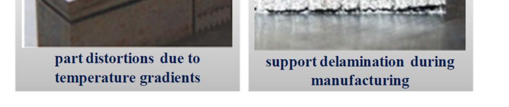
18 Process Planning Support Structures Support options Support failures Source: 18
19 Digital Workflow Slicing 3 D Geometry Data CAD Generate.STL Files Post Process Determine Orientation Process Planning Machine Fix/Repair STL Support Structures Execute Build Slice to Layer Thickness Tool Path Planning and Process Parameters 19


20 Slicing Generate the layer information Input Triangles Sort Triangles in Z Direction Intersect with Z plane Increment Z Output Boundary Data Smooth Boundary Create Boundary Polylines Sliced Files 20
21 Layers Material between slicing planes is called Layer Part is built by sequentially building and stacking layers, resulting in a quantized part along the build axis in steps equal to the layer thickness Layer thickness depends on machine, material, and process parameters 21
22 Errors related to Slicing Staircase effect Surface roughness of surfaces not orthogonal to build direction 22
23 Errors related to Slicing Dimensions in plane of the layer may be created oversized or undersized Features along building axis may be moved up or down one layer, and features smaller than the layer thickness may disappear 23
24 Digital Workflow Tool Path Planning 3 D Geometry Data CAD Generate.STL Files Post Process Determine Orientation Process Planning Machine Fix/Repair STL Support Structures Execute Build Slice to Layer Thickness Tool Path Planning and Process Parameters 24
 Nearly all of these are determined once a material is selected Each material has unique recipe for making")
25 Process Planning Tool Path Tool path planning and process parameters determine how each layer will be built: Laser power/energy density Scan speed Hatch spacing Hatch orientation Boundaries/contours Internal filling (sparse/dense) Nearly all of these are determined once a material is selected Each material has unique recipe for making parts 25
26 Digital Workflow Post Processing 3 D Geometry Data CAD Generate.STL Files Post Process Determine Orientation Process Planning Machine Fix/Repair STL Support Structures Execute Build Slice to Layer Thickness Tool Path Planning and Process Parameters 26
 Machining (e.g., threading, tolerances) Assembly (e.g., mating surfaces/interfaces) Inspection and verification 27")
27 Post Processing Considerations Stress relief and heat treatment Part and support removal Cleaning Secondary operations: Hot isostatic pressing (HIP) Improving surface finish (e.g., shot peening) Machining (e.g., threading, tolerances) Assembly (e.g., mating surfaces/interfaces) Inspection and verification 27
28 Digital Workflow: CAD to Part 3 D Geometry Data CAD Generate.STL Files Key decisions at each step impact the build time, cost, and quality Know where the tradeoffs exist for your specific process/machine Post Process Determine Orientation Process Planning Machine Fix/Repair STL Support Structures Execute Build Slice to Layer Thickness Tool Path Planning and Process Parameters 28
Introduction. File preparation
 White Paper Design and printing guidelines Introduction A print job can be created in either of the following ways: NOTE: HP SmartStream 3D Build Manager supports STL and 3MF files. By using the HP SmartStream
An introduction to. the Additive Direct Digital Manufacturing (DDM) Value Chain. Terrence J. McGowan Associate Technical Fellow Boeing
 Value Chain. Terrence J. McGowan Associate Technical Fellow Boeing") An introduction to the Additive Direct Digital Manufacturing (DDM) Value Chain Terrence J. McGowan Associate Technical Fellow Boeing Copyright 2015 2014 Boeing. All rights reserved. GPDIS_2015.ppt 1 Intro
An introduction to the Additive Direct Digital Manufacturing (DDM) Value Chain Terrence J. McGowan Associate Technical Fellow Boeing Copyright 2015 2014 Boeing. All rights reserved. GPDIS_2015.ppt 1 Intro
STL Rapid Prototyping
 CATIA V5 Training Foils STL Rapid Prototyping Version 5 Release 19 January 2009 EDU_CAT_EN_STL_FI_V5R19 1 About this course Objectives of the course Upon completion of this course you will learn how to
The Quality Of 3D Models
 The Quality Of 3D Models Problems and Solutions for Applications Post-Design Fathi El-Yafi Senior Product Engineer Product Department of EXA Corporation 1 : Overview Status Problems Identified Defect Sources
Materialise Magics 23. What s new
 Materialise Magics 23 What s new Index UX/UI Improvements View cube and general toolbar Settings Performance improvements Magics RP Fillet Cut or punch: lap joint cut Boolean Honeycomb structures Tools
Reverse Engineering Convert STL mesh data to a Solid Edge part model and speed up Product Development.
 Reverse Engineering Convert STL mesh data to a Solid Edge part model and speed up Product Development. Realize innovation. Reverse Engineering Why Reverse Engineering? Convert an existing physical part
Convergent Modeling and Reverse Engineering
 Convergent Modeling and Reverse Engineering 25 October 2017 Realize innovation. Tod Parrella NX Design Product Management Product Engineering Solutions tod.parrella@siemens.com Realize innovation. Siemens
The interfacing software named PSG Slice has been developed using the. computer programming language C. Since, the software has a mouse driven
 CHAPTER 6 DEVELOPMENT OF SLICING MODULE FOR RAPID PROTOTYPING MACHINE 6.1 INTRODUCTION The interfacing software named PSG Slice has been developed using the computer programming language C. Since, the
Chapter 6. Computer Implementations and Examples
 Chapter 6 Computer Implementations and Examples In this chapter, the computer implementations and illustrative examples of the proposed methods presented. The proposed methods are implemented on the 500
Autodesk Moldflow Insight AMI Modeling
 Autodesk Moldflow Insight 2012 AMI Modeling Revision 1, 21 March 2012. This document contains Autodesk and third-party software license agreements/notices and/or additional terms and conditions for licensed
Nouveautés ANSYS pour le calcul structurel et l impression 3D. CADFEM 2017 ANSYS Additive Manufacturing
 Titelmasterformat Journée Technologique durch AddiPole Klicken bearbeiten Nouveautés ANSYS pour le calcul structurel et l impression 3D Titelmasterformat Structural design with durch ANSYS Klicken bearbeiten
SOLIDWORKS FOR MULTI-MATERIAL BUILDS BEST PRACTICES
 WHITE PAPER SOLIDWORKS FOR MULTI-MATERIAL BUILDS BEST PRACTICES AUTHOR COLE HARTMAN SOLIDWORKS FOR MULTI-MATERIAL BUILDS BEST PRACTICES INTRO Stratasys Connex multi-material 3D printing gives you the ability
#SEU Welcome! Solid Edge University 2016
 #SEU 2016 Welcome! Solid Edge University 2016 Realize innovation. Reverse Engineering Convert STL mesh data to a Solid Edge part model and speed up Product Development. Realize innovation. About me Sandeep
ANSYS Discovery SpaceClaim Capabilities
 ANSYS Discovery SpaceClaim Capabilities Rapid Geometry Creation SpaceClaim removes a common geometry bottleneck by putting the power of easy and fast geometry creation into the hands of any designer, engineer,
Introduction to ANSYS FLUENT Meshing
 Workshop 04 CAD Import and Meshing from Conformal Faceting Input 14.5 Release Introduction to ANSYS FLUENT Meshing 2011 ANSYS, Inc. December 21, 2012 1 I Introduction Workshop Description: CAD files will
Introduction to Solid Modeling Parametric Modeling. Mechanical Engineering Dept.
 Introduction to Solid Modeling Parametric Modeling 1 Why draw 3D Models? 3D models are easier to interpret. Simulation under real-life conditions. Less expensive than building a physical model. 3D models
Modeling a Scanned Object with RapidWorks
 Modeling a Scanned Object with RapidWorks RapidWorks allows you to use a scanned point cloud of an object from the NextEngine Desktop 3D Scanner to create a CAD representation of an object. This guide
Synthesizing Geometries for 21st Century Electromagnetics
 ECE 5322 21 st Century Electromagnetics Instructor: Office: Phone: E Mail: Dr. Raymond C. Rumpf A 337 (915) 747 6958 rcrumpf@utep.edu Lecture #19 Synthesizing Geometries for 21st Century Electromagnetics
CONVERTING CAD TO STL
 Overview How CAD files are exported to STL is an important process for accurate building of parts. The step by step process for converting CAD files to STL was taken straight from the mentioned companies
Design for Additive Manufacturing Betatype Capability Demonstration. June 2016
 Design for Additive Manufacturing Capability Demonstration June 2016 Contents 1 Manual & Automatic Optimisation 2 Hardware Used 3 Lattice Generation 4-5 Component Validation Random Lattice Structure 6
This lab exercise has two parts: (a) scan a part using a laser scanner, (b) construct a surface model from the scanned data points.
 scan a part using a laser scanner, (b) construct a surface model from the scanned data points.") 1 IIEM 215: Manufacturing Processes I Lab 4. Reverse Engineering: Laser Scanning and CAD Model construction This lab exercise has two parts: (a) scan a part using a laser scanner, (b) construct a surface
1 IIEM 215: Manufacturing Processes I Lab 4. Reverse Engineering: Laser Scanning and CAD Model construction This lab exercise has two parts: (a) scan a part using a laser scanner, (b) construct a surface
Page 1 of 6
 Page 1 of 6 www.netfabb.com netfabb Professional Features and Package Types netfabb Professional 5.2 netfabb Small Business netfabb Business Edition netfabb Professional is the most easy to use fully professional
NX Fixed Plane Additive Manufacturing Help
 NX 11.0.2 Fixed Plane Additive Manufacturing Help Version #1 1 NX 11.0.2 Fixed Plane Additive Manufacturing Help June 2, 2017 Version #1 NX 11.0.2 Fixed Plane Additive Manufacturing Help Version #1 2 Contents
Successful STLs For Polyjet 3D Printing
 POLYJET BEST PRACTICE Successful STLs For Polyjet 3D Printing Overview This document will help PolyJet 3D Printing users ensure their STL files produce successful 3D printed parts. You ll become familiar
Automatic NC Part. Programming Interface for a UV Laser Ablation Tool
 Automatic NC Part Programming Interface for a UV Laser Ablation Tool by Emir Mutapcic Dr. Pio Iovenitti Dr. Jason Hayes Abstract This research project commenced in December 2001 and it is expected to be
STL File Repair for Beginners
 STL File Repair for Beginners 99% of the time you will be 3D modelling in your favourite CAD programs using their native file formats, and this will likely look perfectly accurate on screen. However in
Section 8.3: Examining and Repairing the Input Geometry. Section 8.5: Examining the Cartesian Grid for Leakages
 Chapter 8. Wrapping Boundaries TGrid allows you to create a good quality boundary mesh using a bad quality surface mesh as input. This can be done using the wrapper utility in TGrid. The following sections
Guide for Geomagic Design X 3D Scan Data Cleanup and Editing. General Information
 Guide for Geomagic Design X 3D Scan Data Cleanup and Editing General Information Geomagic Design X (formerly Rapidform XOR) is an extremely powerful reverse engineering and 3D modeling software that combines
Shape Sculptor Version 5 Release 13. Shape Sculptor
 Shape Sculptor Page 1 Overview Using This Guide Where to Find More Information What's New? Getting Started Entering the Workbench Importing a Polygonal Mesh Decimating a Polygonal Mesh User Tasks Input
Release Notes. Release Date: March, 2018
 Release Notes Release Date: March, 2018 Software: Geomagic Design X Version 2016.2.1 TABLE OF CONTENTS 1 INTRODUCTION 1 COPYRIGHT 1 2 INSTALLATION 2 SYSTEM REQUIREMENTS 2 DOWNLOAD AND INSTALL SOFTWARE
Additive Manufacturing (AM) in a Nutshell Spring 2016 Nick Meisel
 in a Nutshell Spring 2016 Nick Meisel") Additive Manufacturing (AM) in a Nutshell Spring 2016 Nick Meisel Additive vs. Subtractive Manufacturing Traditional subtractive manufacturing involves the removal of unwanted material from a block of
Additive Manufacturing (AM) in a Nutshell Spring 2016 Nick Meisel Additive vs. Subtractive Manufacturing Traditional subtractive manufacturing involves the removal of unwanted material from a block of
STL Rapid Prototyping
 STL Rapid Prototyping Page 1 Preface Using this Guide More Information Conventions What's New Getting Started Basic Surface Tessellation Repairing the Mesh Checking the Mesh Quality User Tasks Starting
SpaceClaim 2015 Release Notes. SpaceClaim 2015 SP1. Release Notes
 SpaceClaim 2015 Release Notes SpaceClaim 2015 SP1 Release Notes Table of Contents SpaceClaim 2015 Release Notes SpaceClaim 2015 Enhancements Overview... 1 Notes... 2 SP1 Items... 3 STL Modeling... 3 Vectorize
T-SCAN 3 3D DIGITIZING
 T-SCAN 3 3D DIGITIZING 2 T-SCAN 3: THE HANDHELD LASER SCANNER Launching the innovative concept of an intuitive-to-use high-precision laser scanner a few years ago, Steinbichler Optotechnik, as the first
CAD package for electromagnetic and thermal analysis using finite element. CAD geometry import in flux : principle and good practices
 CAD package for electromagnetic and thermal analysis using finite element CAD geometry import in flux : principle and good practices Flux Table of contents Table of contents 1. Introduction...1 2. The
Point Cloud - Polygon Mesh. Wannes Van Isacker - Industrial Design 15
 Point Cloud - Polygon Mesh Wannes Van Isacker - Industrial Design 15 3D-SCANNING About 3D Scanning To get started with 3D scanning you first have to understand a little how the scanner works. The scanner
A Method for Slicing CAD Models in Binary STL Format
 6 th International Advanced Technologies Symposium (IATS 11), 16-18 May 2011, Elazığ, Turkey A Method for Slicing CAD Models in Binary STL Format O. Topçu 1, Y. Taşcıoğlu 2 and H. Ö. Ünver 3 1 TOBB University
Successful STLs for 3D Printing
 HOW-TO GUIDE Successful STLs for 3D Printing OVERVIEW This document will help 3D printing users ensure their STL files produce successful 3D printed parts. It will help them become familiar with popular
Offset Triangular Mesh Using the Multiple Normal Vectors of a Vertex
 285 Offset Triangular Mesh Using the Multiple Normal Vectors of a Vertex Su-Jin Kim 1, Dong-Yoon Lee 2 and Min-Yang Yang 3 1 Korea Advanced Institute of Science and Technology, sujinkim@kaist.ac.kr 2 Korea
TOOL PATH GENERATION FOR 5-AXIS LASER CLADDING
 TOOL PATH GENERATION FOR 5-AXIS LASER CLADDING Author: M. Kerschbaumer *, G. Ernst * P. O Leary ** Date: September 24, 2004 * JOANNEUM RESEARCH Forschungsgesellschaft mbh Laser Center Leoben, Leobner Strasse
Lesson 2: Wireframe Creation
 Lesson 2: Wireframe Creation In this lesson you will learn how to create wireframes. Lesson Contents: Case Study: Wireframe Creation Design Intent Stages in the Process Reference Geometry Creation 3D Curve
: Easy 3D Calibration of laser triangulation systems. Fredrik Nilsson Product Manager, SICK, BU Vision
 : Easy 3D Calibration of laser triangulation systems Fredrik Nilsson Product Manager, SICK, BU Vision Using 3D for Machine Vision solutions : 3D imaging is becoming more important and well accepted for
Feature and Topology Detection
 Feature and Topology Detection Greater possibilities with Capvidia extension and PARTsolutions Cadenas Industry Forum February 5th, 2015 Thomas Tillmann Capvidia GmbH Agenda Company Overview Application
PixiRite Tutorials. The Tutorials are designed for PixiRite users,this course is appropriate for beginners and advanced students likewise.
 PixiRite Tutorials The Tutorials are designed for PixiRite users,this course is appropriate for beginners and advanced students likewise. Software Version:5.2.1 Preface PixiRite is a software to improve
Module 1: Basics of Solids Modeling with SolidWorks
 Module 1: Basics of Solids Modeling with SolidWorks Introduction SolidWorks is the state of the art in computer-aided design (CAD). SolidWorks represents an object in a virtual environment just as it exists
Manipulating the Boundary Mesh
 Chapter 7. Manipulating the Boundary Mesh The first step in producing an unstructured grid is to define the shape of the domain boundaries. Using a preprocessor (GAMBIT or a third-party CAD package) you
ME 120: Impeller Model in Solidworks 1/6
 ME 120: Impeller Model in Solidworks 1/6 Steps to Draw Pump Impeller: The steps below show one way to draw the impeller. You should make sure that your impeller is not larger than the one shown or it may
All-in-One Software Solution for Metal Additive Manufacturing
 All-in-One Software Solution for Metal Additive Manufacturing What Makes 3DXpert Ideal for Metal Additive Manufacturing? Specialized Requirements Call for Specialized Software Metal Additive Manufacturing
Working with Neutral Format Surface and Solid Models in Autodesk Inventor
 Working with Neutral Format Surface and Solid Models in Autodesk Inventor JD Mather Pennsylvania College of Technology Session ID ML205-1P In this class we will learn how to utilize neutral format data
What s New Topics in 3.5.1: 1. User Interface 5. Reference Geometry 2. Display 6. Sketch 3. livetransfer 7. Surface / Solid 4. Scan Tools 8.
 ]^ New Release Turning Measured Points into Solid Models What s New Topics in 3.5.1: 1. User Interface 5. Reference Geometry 2. Display 6. Sketch 3. livetransfer 7. Surface / Solid 4. Scan Tools 8. Measure
3D Printing A Processing Approach CONTENTS
 3D Printing A Processing Approach 1 CONTENTS 3D Printing Workflow Digital Modeling Simple Rules for Printable Model Digital Modeling Tools Case 1 Battery Cover Case 2 Housing Case 3 Broken Edge Repair
Laser scanning and CAD conversion accuracy correction of a highly curved engineering component using a precision tactile measuring system
 Laser scanning and CAD conversion accuracy correction of a highly curved engineering component using a precision tactile measuring system Athanasios Giannelis 1, Ioanna Symeonidou 2, Dimitrios Tzetzis
2D CAD. Courseware Issued: DURATION: 64 hrs
 2D CAD Introduction File management Orthographic drawings View management Display management Layer management Selection methods Parametric drawings Symbol creation using block BOM / Joinery details creation
Lecture 6: CAD Import Release. Introduction to ANSYS Fluent Meshing
 Lecture 6: CAD Import 14.5 Release Introduction to ANSYS Fluent Meshing 1 Fluent Meshing 14.5 Assembly meshing Workflow This Lecture Tessellated or Conformal CAD import Cap Inlet/Outlets, Create Domains/BOI
Effort Foundry Inc. Technology is the buzzword heard around the foundry today
 Effort Foundry Inc Technology is the buzzword heard around the foundry today NEW TECHNOLOGY OVERVIEW EFFORT FOUNDRY IS MAKING HUGE INVESTMENTS INTO NEW TECHNOLOGY AS A PART OF OUR CONTINUOUS IMPROVEMENT
Meshing in STAR-CCM+: Recent Advances Aly Khawaja
 Meshing in STAR-CCM+: Recent Advances Aly Khawaja Outline STAR-CCM+: a complete simulation workflow Emphasis on pre-processing technology Recent advances in surface preparation and meshing Continue to
The measuring software of the 4 th generation
 The measuring software of the 4 th generation METROSOFT QUARTIS YOU DECIDE THE PROGRAM Significant measurement results - fast and easy! With Metrosoft QUARTIS, WENZEL Metromec introduces a new software
Accurate Trajectory Control for Five-Axis Tool-Path Planning
 Accurate Trajectory Control for Five-Axis Tool-Path Planning Rong-Shine Lin* and Cheng-Bing Ye Abstract Computer-Aided Manufacturing technology has been widely used for three-axis CNC machining in industry
Lesson 5: Surface Check Tools
 Lesson 5: Surface Check Tools In this lesson, you will learn to check a surface for its continuity and to repair its discontinuities. You will also learn about particularities of a molded surface and how
Generating 3D Meshes from Range Data
 Princeton University COS598B Lectures on 3D Modeling Generating 3D Meshes from Range Data Robert Kalnins Robert Osada Overview Range Images Optical Scanners Error sources and solutions Range Surfaces Mesh
Reasoning Boolean Operation for Modeling, Simulation and Fabrication of Heterogeneous Objects. Abstract
 Reasoning Boolean Operation for Modeling, Simulation and Fabrication of Heterogeneous Objects X. Hu, T. Jiang, F. Lin, and W. Sun Department of Mechanical Engineering and Mechanics, Drexel University,
A New Slicing Procedure for Rapid Prototyping Systems
 Int J Adv Manuf Technol (2001) 18:579 585 2001 Springer-Verlag London Limited A New Slicing Procedure for Rapid Prototyping Systems Y.-S. Liao 1 and Y.-Y. Chiu 2 1 Department of Mechanical Engineering,
Geometric Modeling Topics
 Geometric Modeling Topics George Allen, george.allen@siemens.com Outline General background Convergent modeling Multi-material objects Giga-face lattices Page 2 Boundary Representation (b-rep) Topology
AutoCAD DWG Drawing Limitations in SAP 3D Visual Enterprise 9.0 FP03
 AutoCAD DWG Drawing Limitations in SAP 3D Visual Enterprise 9.0 FP03 AutoCAD Import Limitations The following is a list of AutoCAD features that will not give an expected viewable when using SAP 3D Visual
Roger Wende Acknowledgements: Lu McCarty, Johannes Fieres, Christof Reinhart. Volume Graphics Inc. Charlotte, NC USA Volume Graphics
 Roger Wende Acknowledgements: Lu McCarty, Johannes Fieres, Christof Reinhart Volume Graphics Inc. Charlotte, NC USA 2018 Volume Graphics VGSTUDIO MAX Modules Inline Fiber Orientation Analysis Nominal/Actual
CAD INTEROPERABILITY SOFTWARE SUITE
 CAD INTEROPERABILITY SOFTWARE SUITE 1 3D_Evolution Conversion Engine is today s leading MCAD collaboration suite. Designed for a seamless, integrated process, it is the ideal enhancement for your PLM environment.
Sharif University of Technology. Session # Rapid Prototyping
 Advanced Manufacturing Laboratory Department of Industrial Engineering Sharif University of Technology Session # Rapid Prototyping Contents: Rapid prototyping and manufacturing RP primitives Application
IJCSI International Journal of Computer Science Issues, Vol. 9, Issue 5, No 2, September 2012 ISSN (Online):
:") www.ijcsi.org 126 Automatic Part Primitive Feature Identification Based on Faceted Models Gandjar Kiswanto 1 and Muizuddin Azka 2 1 Department of Mechanical Engineering, Universitas Indonesia Depok, 16424,
www.ijcsi.org 126 Automatic Part Primitive Feature Identification Based on Faceted Models Gandjar Kiswanto 1 and Muizuddin Azka 2 1 Department of Mechanical Engineering, Universitas Indonesia Depok, 16424,
Training Guide Getting Started with WorkXplore 3D
 Training Guide Getting Started with WorkXplore 3D Table of Contents Table of Contents 1 Training Guide Objectives 1-1 2 WorkXplore 3D Environment 2-1 3 Importing and Opening CAD Files 3-1 3.1 Importing
Image courtesy of Local Motors Inc.
 Image courtesy of Local Motors Inc. Image courtesy of Local Motors Inc. Advanced Materials and Manufacturing Advanced Materials and Manufacturing The promise of advanced materials and manufacturing
Model data extraction. Mass property data. Mass property data. Mass property data. Integral Processes. Units and volume
 Model data extraction Most solid modelers permit information to be extracted directly from the model database. Graphic profile data 2D drawings annotation Solid model database details the distribution
Lecture 7: Mesh Quality & Advanced Topics. Introduction to ANSYS Meshing Release ANSYS, Inc. February 12, 2015
 Lecture 7: Mesh Quality & Advanced Topics 15.0 Release Introduction to ANSYS Meshing 1 2015 ANSYS, Inc. February 12, 2015 Overview In this lecture we will learn: Impact of the Mesh Quality on the Solution
(1)C-(CH) BU, Printed in Japan
C-(CH) BU, Printed in Japan") Export permission by the Japanese government may be required for exporting our products according to the Foreign Exchange and Foreign Trade Law. Please consult our sales office near you before you export
Export permission by the Japanese government may be required for exporting our products according to the Foreign Exchange and Foreign Trade Law. Please consult our sales office near you before you export
Advanced geometry tools for CEM
 Advanced geometry tools for CEM Introduction Modern aircraft designs are extremely complex CAD models. For example, a BAE Systems aircraft assembly consists of over 30,000 individual components. Since
SolidView Features List
 SolidView 2012.0 Features List SolidView/Lite Features View, measure and modify SVD fi les from SolidView/Pro. View STL, SFX, SolidWorks and VRML CAD fi les. SolidView Features View, measure, modify and
Quick Surface Reconstruction
 CATIA V5 Training Exercises Quick Surface Reconstruction Version 5 Release 19 August 2008 EDU_CAT_EN_QSR_FX_V5R19 1 Table of Contents Master Exercise Presentation:Plastic Bottle 3 Design Intent - Plastic
COPYRIGHTED MATERIAL RAPID PROTOTYPING PROCESS
 2 RAPID PROTOTYPING PROCESS The objective of rapid prototyping is to quickly fabricate any complex-shaped, three-dimensional part from CAD data. Rapid prototyping is an example of an additive fabrication
SpaceClaim 2015 Release Notes. SpaceClaim Release Notes
 SpaceClaim 2015 Release Notes SpaceClaim 2015 Release Notes Table of Contents SpaceClaim 2015 Release Notes SpaceClaim 2015 Beta Enhancements Overview... 1 Notes... 2 Pull... 3 Move... 14 Points... 15
Geometric Modeling. Introduction
 Geometric Modeling Introduction Geometric modeling is as important to CAD as governing equilibrium equations to classical engineering fields as mechanics and thermal fluids. intelligent decision on the
Topology Optimization for Designers
 TM Topology Optimization for Designers Siemens AG 2016 Realize innovation. Topology Optimization for Designers Product Features Uses a different approach than traditional Topology Optimization solutions.
Example of 3D Injection Molding CAE Directly Connected with 3D CAD
 3D TIMON Example of 3D Injection Molding CAE Directly Connected with 3D CAD 1 Background Problem of Data Translation from 3D CAD to CAE 3D TIMON Difficulty to Generate mesh Automatically Topologically
Improvements Metrosoft QUARTIS R12
 Improvements Metrosoft QUARTIS R12 Improvements Metrosoft QUARTIS R12 At a glance Metrosoft QUARTIS R12 offers a wide range of improvements for all users and significantly contributes to optimize daily
Steps to Print (without supports) This will take you from Meshmixer to the PSU PrintDepot
 This will take you from Meshmixer to the PSU PrintDepot") Steps to Print (without supports) This will take you from Meshmixer to the PSU PrintDepot Read this first to understand some of the dilemmas a model can have and ways to avoid printing problems: http://www.3dshook.com/2016/05/how-to-optimize-a-3d-model-for-3dprinting/#normal
Steps to Print (without supports) This will take you from Meshmixer to the PSU PrintDepot Read this first to understand some of the dilemmas a model can have and ways to avoid printing problems: http://www.3dshook.com/2016/05/how-to-optimize-a-3d-model-for-3dprinting/#normal
Additive Fertigung durchgängig und effizient. Industrieller 3D-Druck von der Idee bis zum fertigen Bauteil
 Additive Fertigung durchgängig und effizient Industrieller 3D-Druck von der Idee bis zum fertigen Bauteil Realize innovation. Was erwartet sie heute? 08:30 Empfang mit Frühstück 09:00 Generative Design
CHAPTER 5 USE OF STL FILE FOR FINITE ELEMENT ANALYSIS
 CHAPTER 5 USE OF STL FILE FOR FINITE ELEMENT ANALYSIS 5.1 Introduction: Most CAD software in the market can generate STL files, and these are generally used for prototyping and rendering purposes. These
Licom Systems Ltd., Training Course Notes. 3D Surface Creation
 , Training Course Notes Work Volume and Work Planes...........................1 Overview..........................................1 Work Volume....................................1 Work Plane......................................1
Magics 20. What s new?
 Magics 20 What s new? Magics 20, Enabling the Next Generation Nobody can predict the future, but independent of the direction you and other companies will choose, we already developed the technology to
This tutorial will take you all the steps required to import files into ABAQUS from SolidWorks
 ENGN 1750: Advanced Mechanics of Solids ABAQUS CAD INTERFACE TUTORIAL School of Engineering Brown University This tutorial will take you all the steps required to import files into ABAQUS from SolidWorks
Version 2011 R1 - Router
 GENERAL NC File Output List NC Code Post Processor Selection Printer/Plotter Output Insert Existing Drawing File Input NC Code as Geometry or Tool Paths Input Raster Image Files Convert Raster to Vector
SolidView Features List
 SolidView 2012.1 Features List SolidView/Lite Features View, measure and modify SVD fi les from SolidView/Pro. View STL, SFX, SolidWorks and VRML CAD fi les. SolidView Features View, measure, modify and
ROBUST PROTOTYPING. Jana K. Chari Dr. Jerry L. Hall
 ROBUST PROTOTYPING Jana K. Chari Dr. Jerry L. Hall Department of Mechanical Engineering Engel Manufacturing Laboratory Iowa State University Ames, IA 50011 Submitted for Publication in Solid Freeform Fabrication
Release Notes. Release Date: June, 2018
 Release Notes Release Date: June, 2018 Software: Geomagic Control X Version 2018.1.1 TABLE OF CONTENTS 1 INTRODUCTION 1 COPYRIGHT 1 2 INSTALLATION 2 SYSTEM REQUIREMENTS 2 DOWNLOAD AND INSTALL SOFTWARE
3DReshaper Help DReshaper Beginner's Guide. Surveying
 3DReshaper Beginner's Guide Surveying 1 of 29 Cross sections Exercise: Tunnel analysis Surface analysis Exercise: Complete analysis of a concrete floor Surveying extraction Exercise: Automatic extraction
SimLab 14.2 Release Notes
 SimLab 14.2 Release Notes Highlights SimLab 14.2 comes with various changes that improve performance and graphics rendering. In addition to java scripting, python scripting is introduced. The enhancements,
Page 1 of 7. Please contact you netfabb distributor for more information and ordering.
 Page 1 of 7 New Features in netfabb Professional 5 Overview based on netfabb Professional 5.1 including most important features from previous netfabb versions Usability improvements Automatic Repair one-click
AND INSPECTION SOFTWARE
 Simple. Integrated. Powerful. The Leading REVERSE ENGINEERING AND INSPECTION SOFTWARE About Geomagic Geomagic is a leading provider of 3D software for creating digital models of physical objects. The company
Preparing Models for CAE and MFG Applications
 Preparing Models for CAE and MFG Applications Closing the Gap Abdul Shammaa Elysium Inc. GPDIS_2013.ppt 1 The Gap CAD models are often not readily usable by downstream applications A mathematically valid
What's New in BobCAD-CAM V29
 Introduction Release Date: August 31, 2016 The release of BobCAD-CAM V29 brings with it, the most powerful, versatile Lathe module in the history of the BobCAD-CAM software family. The Development team
Efficient slicing procedure based on adaptive layer depth normal image
 This is the Pre-Published Version Accepted Manuscript Efficient slicing procedure based on adaptive layer depth normal image Long Zeng, Lip Man-Lip Lai, Di Qi, Yuen-Hoo Lai, Matthew Ming-Fai Yuen PII:
Dedicated Software Algorithms for 3D Clouds of Points
 Dedicated Software Algorithms for 3D Clouds of Points Introduction AQSENSE develops and commercializes 3D image acquisition and processing technologies that allow high speed in-line 100% production inspection,