B R O A D B A N D P O L A R I Z I N G B E A M S P L I T T E R C U B E S I N 3 0 M M C A G E C U B E S
|
|
|
- Ambrose Cook
- 6 years ago
- Views:
Transcription


1 B R O A D B A N D P O L A R I Z I N G B E A M S P L I T T E R C U B E S I N 3 0 M M C A G E C U B E S Transmitted Beam Extinction Ratio: >1000:1 Reflects S Polarization 90º SM1 and 30 mm Cage System Compatible Engraved Housing CM1-CC CM1-PBS nm CM1-PBS nm CM1-PBS nm
2 O V E R V I E W Features Coating Range Damage Threshold 30 mm Cage and SM1 Lens Tube Compatible Mounts Wavelength Ranges from 420 to 1600 nm Extinction Ratio T P :T S > 1000:1 R s :R p ~ 100:1 Coating and Cement Layer Not to Scale nm nm nm CW a Pulse CW a Pulse CW a,b Pulse 50 W/cm at 532 nm, Ø0.015 mm 2 J/cm 2 at 532 nm, 10 ns, 10 Hz 50 W/cm at 810 nm, Ø0.019 mm 2 J/cm 2 at 810 nm, 10 ns, 10 Hz 2000 W/cm at 1064 nm, Ø0.018 mm 2 J/cm 2 at 1064 nm, 10 ns, 10 Hz The polarizing beamsplitting cubes on this page have a dielectric coating along the diagonal interface between the two right angle prisms that make up the cube. This coating reflects s-polarized light, while transmitting p-polarized light. For highest polarization purity, use the transmitted beam, which offers a 1000:1 (T p :T s ) extinction ratio. The reflected beam will only have an extinction ratio of roughly 20:1 to 100:1, depending on the beamsplitter. The entrance and exit faces of this cube have broadband antireflective coatings that minimize losses due to reflections. The dielectric beamsplitting coating is applied to the hypotenuse of one of the two prisms that make up the cube. Then, cement is used to bind the two prism halves together. For best performance the light must enter through the entrace face, as depicted by the engraving on the mount (similar to that shown above). Each beamsplitter cube is epoxied within the cage cube mount and cannot be removed from the mount. We also offer empty 30 mm cage cubes that are compatible with our line of unmounted beamsplitter cubes. CW a,b 2000 W/cm at 1542 nm, Ø0.033 mm nm Pulse 5 J/cm 2 at 1542 nm, 10 ns, 10 Hz a The power density of your beam should be calculated in terms of W/cm. For an explanation of why the linear power density provides the best metric for long pulse and CW sources, please see the Damage Thresholds tab. b The stated damage threshold is a certification measurement, as opposed to a true damage threshold (i.e., the optic was able to withstand the maximum output of the laser with no damage). For a complete selection of our cube-mounted optics, please see the Mounted Optics Guide tab. For applications requiring a higher damage threshold, we offer high-power polarizing beamsplitting cubes. We also offer polarizing beamsplitter cubes at laser line wavelengths, which have a high extinction ratio of 3000:1 (T P :T S ).
 R avg < 0.5% R avg < 0.5% R avg < 0.5% R avg < 0.5% Ports 4 Ports With SM1 (1.")
3 S P E C S CM1-PBS251 and CCM1-PBS251/M CM1-PBS252 and CCM1-PBS252/M CM1-PBS253 and CCM1-PBS253/M CM1-PBS254 and CCM1-PBS254/M AR-Coating Range nm nm nm nm AR Coating (0 Incident Angle) R avg < 0.5% R avg < 0.5% R avg < 0.5% R avg < 0.5% Ports 4 Ports With SM1 (1.035"-40) Thread Beamsplitter Material N-SF1 Extinction Ratio a T p :T s >1,000:1 Transmission Efficiency b T p > 90% Reflection Efficiency b R s > 99.5% Transmitted Beam Deviation c Reflected Beam Deviation d Clear Aperture Surface Flatness Transmitted Wavefront Error Surface Quality <5 arcmin 90 ± 20 arcmin Ø20.3 mm 633 nm 633 nm Scratch-Dig The extinction ratio (ER) is the ratio of the maximum transmission of a linearly polarized signal when the polarizer s axis is aligned with the signal to the minimum transmission when the polarizer is rotated by 90. Transmission and reflection data is based on that of the beamsplitter coating and does not account for the BBAR surface coating. Defined with respect to the non-polarizing beamsplitter cube, not the mechanical housing. Defined with respect to the mechanical housing. Thorlabs offers three types of mounted beamsplitters: Polarization Insensitive Beamsplitting Cubes, Polarizing Beamsplitting Cubes (presented below), and the Pellicle Beamsplitters. A large variety of unmounted beamsplitters are also available.

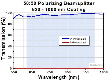
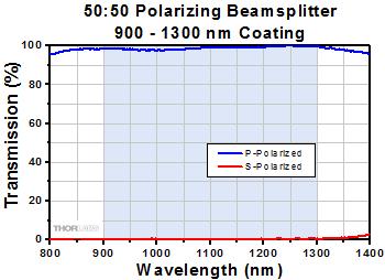
4 G R A P H S


5 Beamsplitter Selection Guide Thorlabs offers five main types of beamsplitters: Pellicle, Cube, Plate, Economy, and Polka Dot. Each type has distinct advantages and disadvantages. Reflected Beam: Legend for Beam Diagrams Transmitted Beam: Pellicle Beamsplitters - Pellicle beamsplitters are the best choice when dispersion must be kept to a minimum. They virtually eliminate multiple reflections commonly associated with thicker glass beamsplitters, thus preventing ghosting. In addition, unlike plate beamsplitters, there is a negligible effect on the propagation axis of the transmitted beam with respect to the incident beam. Pellicle beamsplitters have two disadvantages: They exhibit sinusodial oscillations in the splitting ratio as a function of wavelength, due to thin film interference effects. Click Here for more details. They are also extremely delicate. Since they are fabricated by stretching a nitrocellulose membrane over a flat metal frame, the beamsplitter cannot be touched without destroying the optic. Thorlabs offers pellicle beamsplitters mounted in metal rings for use in kinematic mounts as well as 30 mm cage cube-mounted pellicles. Beamsplitting Cubes Thorlabs beamsplitter cubes are composed of two right-angled prisms. A dielectric coating, which is capable of reflecting and transmitting a portion of the incident beam, is applied to the hypotenuse surface. Since there is only one reflecting surface, this design inherently avoids ghost images, which sometimes occur with platetype beamsplitters. Antireflection coatings are available on the entrance and exit faces of certain models to minimize back reflections. As well as providing a cost-effective solution, another advantage of the beamsplitting cube is the minimal shift it causes to the path of the transmitted beam. Thorlabs offers both polarizing and nonpolarizing beamsplitting cubes, in mounted and unmounted configurations. Mounted beamsplitters are available that are compatible with our 16 mm cage systems as well as our 30 mm cage systems. Polarizing Beamsplitters - Thorlabs polarizing plate and cube beamsplitters split randomly polarized beams into two orthogonal, linearly polarized components (S and P), as shown in the diagram to the right. S-polarized light is reflected at a 90 angle with respect to the incident beam while p-polarized light is transmitted. Polarizing beamsplitters are useful in applications where the two polarization components are to be analyzed or used simultaneously. Thorlabs offers broadband 16 mm cage cube-mounted, broadband 30 mm cage cube-mounted, and broadband unmounted polarizing beamsplitter cubes, as well as laser line 30 mm cage cube-mounted and laser line unmounted cubes. Additionally, Thorlabs offers wire grid polarizing beamsplitters which have a larger Angle of Incidence and work with uncollimated light. For applications requiring higher power, we also offer high-power polarizing beamsplitting cubes. Non-Polarizing Beamsplitting Cubes - These cubes provide a 50:50 splitting ratio that is nearly independent of the polarization of the incident light. The low polarization dependence of the metallic-dielectric coating allows the transmission and reflection for s- and p-polarization states to be within 10% or 15% of each other. These beamsplitters are particularly useful with randomly polarized lasers and are specifically designed for applications in which polarization effects must be minimized. Thorlabs offers 16 mm cage cube-mounted, 30 mm cage cube-mounted, and unmounted beamsplitter cubes. Plate Beamsplitters - Thorlabs' plate beamsplitters are optimized for an incidence angle of 45 and feature a dielectric coating on the front surface for long-term stability. To help reduce unwanted interference effects (e.g., ghost images) caused by the interaction of light reflected from the front and back surfaces of the optic, a wedge has been added to the round versions of these beamsplitters. Dispersion, ghosting, and shifting of the beam may all be potential problems, however. These are the best choice for a general-purpose beamsplitter. Thorlabs offers both polarizing and nonpolarizing plate beamsplitters. Economy Beamsplitters - These are the most cost effective of all the beamsplitter types. Thorlabs' economy beamsplitters, which have an exposed oxide coating on one side and are uncoated on the other side, are designed to have either a 50:50 or 30:70 splitting ratio throughout the visible spectrum ( nm) when used with unpolarized light incident at 45. Please note that the Fresnel reflections off of the uncoated back surface of these economy beamsplitters can lead to interference effects in the reflected beam. For applications sensitive to these effects, consider using a beamsplitting cube or a pellicle beamsplitter.


6 Polka Dot Beamsplitters - This type of beamsplitter consists of a glass substrate with a vacuum-deposited reflective coating that is applied over an array of apertures, giving the beamsplitter a "polka dot" appearance. Half of the incident beam is reflected from the coating, and half of the beam is transmitted through the uncoated portion of the substrate. Polka dot beamsplitters are useful over a wide wavelength range and are negligibly angle sensitive, which makes them ideal for splitting the energy emitted from a radiant source. These are not recommended for imaging applications, such as interferometry, as the polka dot pattern will affect the image. M O U N T E D O P T I C S G U I D E 30 mm Cage-Cube-Mounted Optics Selection Guide The table below provides links to all of our 30 mm Cage-Cube-Mounted optics. For our selection of 16 mm Cage-Cube-Mounted Optics, please see our 16 mm Cage Systems guide. Non-Polarizing Beamsplitter Cube Polarizing Beamsplitter Cube High-Power Polarizing Beamsplitter Cube Pellicle Beamsplitters Laser Line Polarizing Beamsplitter Cube Circular / Variable Polarizers Penta Prisms Turning Mirrors Variable Beamsplitters / Attenuators 30 mm Cage Cube Empty Optic Mounts Selection Guide Rectangular Dichroic Mirrors and Filters Empty Compact 30 mm Cage Cube

 2 J/cm 2 at 810 nm, 10 ns, 10 Hz 620-1000 nm (CW) a 50 W/cm at 810 nm, Ø0.")
7 Damage Threshold Data for Thorlabs' Polarizing Beamsplitter Cubes The specifications to the right are measured data for Thorlabs' polarizing beamsplitter cubes. Damage threshold specifications are constant for a given wavelength range, regardless of the size of the beamsplitter. Damage Threshold Specifications Coating Wavelength Range Damage Threshold nm (Pulse) 2 J/cm 2 at 532 nm, 10 ns, 10 Hz nm (CW) a 50 W/cm at 532 nm, Ø0.015 mm nm (Pulse) 2 J/cm 2 at 810 nm, 10 ns, 10 Hz nm (CW) a 50 W/cm at 810 nm, Ø0.019 mm nm (Pulse) 2 J/cm 2 at 1064 nm, 10 ns, 10 Hz nm (CW) a,b 2000 W/cm at 1064 nm, Ø0.018 mm nm (Pulse) 5 J/cm 2 at 1542 nm, 10 ns, 10 Hz nm (CW) a,b 2000 W/cm at 1542 nm, Ø0.033 mm The power density of your beam should be calculated in terms of W/cm. For an explanation of why the linear power density provides the best metric for long pulse and CW sources, please see the "Continuous Wave and Long-Pulse Lasers" section below. The stated damage threshold is a certification measurement, as opposed to a true damage threshold (i.e., the optic was able to withstand the maximum output of the laser with no damage). Laser Induced Damage Threshold Tutorial The following is a general overview of how laser induced damage thresholds are measured and how the values may be utilized in determining the appropriateness of an optic for a given application. When choosing optics, it is important to understand the Laser Induced Damage Threshold (LIDT) of the optics being used. The LIDT for an optic greatly depends on the type of laser you are using. Continuous wave (CW) lasers typically cause damage from thermal effects (absorption either in the coating or in the substrate). Pulsed lasers, on the other hand, often strip electrons from the lattice structure of an optic before causing thermal damage. Note that the guideline presented here assumes room temperature operation and optics in new condition (i.e., within scratch-dig spec, surface free of contamination, etc.). Because dust or other particles on the surface of an optic can cause damage at lower thresholds, we recommend keeping surfaces clean and free of debris. For more information on cleaning optics, please see our Optics Cleaning tutorial. Testing Method Thorlabs' LIDT testing is done in compliance with ISO/DIS11254 specifications. A standard 1-on-1 testing regime is performed to test the damage threshold. First, a low-power/energy beam is directed to the optic under test. The optic is exposed in 10 locations to this laser beam for a set duration of time (CW) or number of pulses (pulse repetition frequency specified). After exposure, the optic is examined by a microscope (~100X magnification) for any visible damage. The number of locations that are damaged at a particular power/energy level is recorded. Next, the power/energy is either increased or decreased and the optic is exposed at 10 new locations. This process is repeated until damage is observed. The damage threshold is then assigned to be the highest power/energy that the optic can withstand without causing damage. A histogram such as that below represents the testing of one BB1-E02 mirror. The photograph above is a protected aluminumcoated mirror after LIDT testing. In this particular test, it handled 0.43 J/cm 2 (1064 nm, 10 ns pulse, 10 Hz, Ø1.000 mm) before damage. According to the test, the damage threshold of the mirror was 2.00 J/cm 2 (532 nm, 10 ns pulse, 10 Hz, Ø0.803 mm). Please keep in mind that these tests are performed on clean optics, as dirt and contamination can significantly lower the damage threshold of a component. While the test results are only representative of Example Test Data Fluence # of Tested Locations Locations with Damage Locations Without Damage 1.50 J/cm J/cm
8 one coating run, Thorlabs specifies damage threshold values that account for coating variances J/cm J/cm Continuous Wave and Long-Pulse Lasers When an optic is damaged by a continuous wave (CW) laser, it is usually due to the melting of the surface as a result of absorbing the laser's energy or damage to the 3.00 J/cm J/cm optical coating (antireflection) [1]. Pulsed lasers with pulse lengths longer than 1 µs can be treated as CW lasers for LIDT discussions. Additionally, when pulse lengths are between 1 ns and 1 µs, LIDT can occur either because of absorption or a dielectric breakdown (must check both CW and pulsed LIDT). Absorption is either due to an intrinsic property of the optic or due to surface irregularities; thus LIDT values are only valid for optics meeting or exceeding the surface quality specifications given by a manufacturer. While many optics can handle high power CW lasers, cemented (e.g., achromatic doublets) or highly absorptive (e.g., ND filters) optics tend to have lower CW damage thresholds. These lower thresholds are due to absorption or scattering in the cement or metal coating. Pulsed lasers with high pulse repetition frequencies (PRF) may behave similarly to CW beams. Unfortunately, this is highly dependent on factors such as absorption and thermal diffusivity, so there is no reliable method for determining when a high PRF laser will damage an optic due to thermal effects. For beams with a large PRF both the average and peak powers must be compared to the equivalent CW power. Additionally, for highly transparent materials, there is little to no drop in the LIDT with increasing PRF. In order to use the specified CW damage threshold of an optic, it is necessary to know the following: 1. Wavelength of your laser 2. Linear power density of your beam (total power divided by 1/e 2 beam diameter) 3. Beam diameter of your beam (1/e 2 ) LIDT in linear power density vs. pulse length and spot size. For long 4. Approximate intensity profile of your beam (e.g., Gaussian) pulses to CW, linear power density becomes a constant with spot size. This graph was obtained from [1]. The power density of your beam should be calculated in terms of W/cm. The graph to the right shows why expressing the LIDT as a linear power density provides the best metric for long pulse and CW sources. In this regime, the LIDT given as a linear power density can be applied to any beam diameter; one does not need to compute an adjusted LIDT to adjust for changes in spot size. This calculation assumes a uniform beam intensity profile. You must now consider hotspots in the beam or other non-uniform intensity profiles and roughly calculate a maximum power density. For reference, a Gaussian beam typically has a maximum power density that is twice that of the uniform beam (see lower right). Now compare the maximum power density to that which is specified as the LIDT for the optic. If the optic was tested at a wavelength other than your operating wavelength, the damage threshold must be scaled appropriately. A good rule of thumb is that the damage threshold has a linear relationship with wavelength such that as you move to shorter wavelengths, the damage threshold decreases (i.e., a LIDT of 10 W/cm at 1310 nm scales to 5 W/cm at 655 nm): While this rule of thumb provides a general trend, it is not a quantitative analysis of LIDT vs wavelength. In CW applications, for instance, damage scales more strongly with absorption in the coating and substrate, which does not necessarily scale well with wavelength. While the above procedure provides a good rule of thumb for LIDT values, please contact Tech Support if your wavelength is different from the specified LIDT wavelength. If your power density is less than the adjusted LIDT of the optic, then the optic should work for your application. Please note that we have a buffer built in between the specified damage thresholds online and the tests which we have done, which accommodates variation between batches. Upon request, we can provide individual test information and a testing certificate. The damage analysis will be carried out on a similar optic (customer's optic will not be damaged). Testing may result in additional costs or lead times. Contact Tech Support for more information. Pulsed Lasers As previously stated, pulsed lasers typically induce a different type of damage to the optic than CW lasers. Pulsed lasers often do not heat the optic enough to damage it; instead, pulsed lasers produce strong electric fields capable of inducing dielectric breakdown in the material. Unfortunately, it can be very difficult to compare the LIDT specification of an optic to your laser. There are multiple regimes in which a pulsed laser can damage an optic and this is based on the laser's pulse length. The highlighted columns in the table below outline the relevant pulse lengths for our specified LIDT values. Pulses shorter than 10-9 s cannot be compared to our specified LIDT values with much reliability. In this ultra-short-pulse regime various mechanics, such as multiphoton-avalanche ionization, take over as the predominate damage mechanism [2]. In contrast, pulses between 10-7 s and 10-4 s may cause damage to an optic either because of dielectric breakdown or thermal effects. This means that both CW and pulsed damage thresholds must be compared to the laser beam to determine whether the optic is suitable for your application.
9 Pulse Duration t < 10-9 s 10-9 < t < 10-7 s 10-7 < t < 10-4 s t > 10-4 s Damage Mechanism Relevant Damage Specification Dielectric Breakdown or Avalanche Ionization Dielectric Breakdown Thermal Thermal N/A Pulsed Pulsed and CW CW When comparing an LIDT specified for a pulsed laser to your laser, it is essential to know the following: 1. Wavelength of your laser 2. Energy density of your beam (total energy divided by 1/e 2 area) 3. Pulse length of your laser 4. Pulse repetition frequency (prf) of your laser 5. Beam diameter of your laser (1/e 2 ) 6. Approximate intensity profile of your beam (e.g., Gaussian) The energy density of your beam should be calculated in terms of J/cm 2. The graph to the right shows why expressing the LIDT as an energy density provides the best metric for short pulse sources. In this regime, the LIDT given as an energy density can be applied to any beam diameter; one does not need to compute an adjusted LIDT to adjust for changes in spot size. This calculation assumes a uniform beam intensity profile. You must now adjust this energy density to account for hotspots or other nonuniform intensity profiles and roughly calculate a maximum energy density. For reference a Gaussian beam typically has a maximum energy density that is twice that of the 1/e 2 LIDT in energy density vs. pulse length and spot size. For short pulses, beam. energy density becomes a constant with spot size. This graph was obtained from [1]. Now compare the maximum energy density to that which is specified as the LIDT for the optic. If the optic was tested at a wavelength other than your operating wavelength, the damage threshold must be scaled appropriately [3]. A good rule of thumb is that the damage threshold has an inverse square root relationship with wavelength such that as you move to shorter wavelengths, the damage threshold decreases (i.e., a LIDT of 1 J/cm 2 at 1064 nm scales to 0.7 J/cm 2 at 532 nm): You now have a wavelength-adjusted energy density, which you will use in the following step. Beam diameter is also important to know when comparing damage thresholds. While the LIDT, when expressed in units of J/cm², scales independently of spot size; large beam sizes are more likely to illuminate a larger number of defects which can lead to greater variances in the LIDT [4]. For data presented here, a <1 mm beam size was used to measure the LIDT. For beams sizes greater than 5 mm, the LIDT (J/cm2) will not scale independently of beam diameter due to the larger size beam exposing more defects. The pulse length must now be compensated for. The longer the pulse duration, the more energy the optic can handle. For pulse widths between ns, an approximation is as follows: Use this formula to calculate the Adjusted LIDT for an optic based on your pulse length. If your maximum energy density is less than this adjusted LIDT maximum energy density, then the optic should be suitable for your application. Keep in mind that this calculation is only used for pulses between 10-9 s and 10-7 s. For pulses between 10-7 s and 10-4 s, the CW LIDT must also be checked before deeming the optic appropriate for your application. Please note that we have a buffer built in between the specified damage thresholds online and the tests which we have done, which accommodates variation between batches. Upon request, we can provide individual test information and a testing certificate. Contact Tech Support for more information. [1] R. M. Wood, Optics and Laser Tech. 29, 517 (1997). [2] Roger M. Wood, Laser-Induced Damage of Optical Materials (Institute of Physics Publishing, Philadelphia, PA, 2003). [3] C. W. Carr et al., Phys. Rev. Lett. 91, (2003). [4] N. Bloembergen, Appl. Opt. 12, 661 (1973).
10 P O L A R I Z E R G U I D E Polarizer Selection Guide Thorlabs offers a diverse range of polarizers, including wire grid, film, calcite, alpha-bbo, rutile, and beamsplitting polarizers. Collectively, our line of wire grid polarizers offers coverage from the visible range to the beginning of the Far-IR range. Our nanoparticle linear film polarizers provide extinction ratios as high as :1. Alternatively, our other film polarizers offer an affordable solution for polarizing light from the visible to the Near-IR. Next, our beamsplitting polarizers allow for use of the reflected beam, as well as the more completely polarized transmitted beam. Finally, our alpha-bbo (UV), calcite (visible to Near-IR), rutile (Near-IR to Mid-IR), and yttrium orthovanadate (YVO 4 ) (Near-IR to Mid-IR) polarizers each offer an exceptional extinction ratio of :1 within their respective wavelength ranges. To explore the available types, wavelength ranges, extinction ratios, transmission, and available sizes for each polarizer category, click in the appropriate row below. Wire Grid Polarizers Film Polarizers Beamsplitting Polarizers alpha-bbo Polarizers Calcite Polarizers Quartz Polarizers Magnesium Fluoride Polarizers Yttrium Orthovanadate (YVO 4 ) Polarizers Rutile Polarizers Click on the graph icons in this column to view a transmission curve for the corresponding polarizer. Each curve represents one substrate sample or coating run and is not guaranteed. Mounted in a protective box, unthreaded ring, or cylinder that indicates the polarization axis. Available unmounted or in an SM05-threaded (0.535"-40) mount that indicates the polarization axis. Available unmounted or in an SM1-threaded (1.035"-40) mount that indicates the polarization axis. Available unmounted or mounted in cubes for cage system compatibility. Calcite's transmittance of light near 350 nm is typically around 75% (see Transmission column). Available unmounted or in an unthreaded Ø1/2" housing. The transmission curves for calcite are valid for linearly polarized light with a polarization axis aligned with the mark on the polarizer's housing. The 1064 nm V coating corresponds to a -C26 suffix in the item number. Available unmounted or mounted in a protective box or unthreaded cylinder that indicates the polarization axis.
 polarizing beamsplitter cubes.")
11 Cube-Mounted Polarizing Beamsplitting Cubes Transmitted Extinction Ratio: T p :T s > 1,000:1 Transmission Efficiency: T p > 90% Reflection Efficiency: R s > 99.5% Four SM1-Threaded Ports 4-40 Tapped Holes for 30 mm Cage Our CM1-PBS series of mounted polarizing beamsplitter cubes utilizes our 1" (25.4 mm) polarizing beamsplitter cubes. Each cube is mounted in a 30 mm cage system compatible housing, which also offers four SM1 threaded ports. As these cubes offer cage and lens tube system compatibility, they can be used in a variety of applications. The bottom of each cube has an M6 x 0.5 or M4 tap, but adapters are included with the M6 x 0.5 tapped cubes for 8-32 or M4 mounting (the M6 x 0.5 tap is only compatible with the included adapters). Item # CM1-PBS251 and CCM1-PBS251/M CM1-PBS252 and CCM1-PBS252/M CM1-PBS253 and CCM1-PBS253/M CM1-PBS254 and CCM1-PBS254/M Transmission Part Number Description Price Availability CCM1-PBS251/M Customer Inspired!30 mm Cage-Cube-Mounted Polarizing Beamsplitter Cube, nm, M4 Tap $ Today CCM1-PBS252/M Customer Inspired!30 mm Cage-Cube-Mounted Polarizing Beamsplitter Cube, nm, M4 Tap $ Today CCM1-PBS253/M Customer Inspired!30 mm Cage-Cube-Mounted Polarizing Beamsplitter Cube, nm, M4 Tap $ Today CCM1-PBS254/M Customer Inspired!30 mm Cage-Cube-Mounted Polarizing Beamsplitter Cube, nm, M4 Tap $ Today CM1-PBS mm Cage-Cube-Mounted Polarizing Beamsplitter Cube, nm, 8-32 and M4 Adapters $ Lead Time CM1-PBS mm Cage-Cube-Mounted Polarizing Beamsplitter Cube, nm, 8-32 and M4 Adapters $ Today CM1-PBS mm Cage-Cube-Mounted Polarizing Beamsplitter Cube, nm, 8-32 and M4 Adapters $ Lead Time CM1-PBS mm Cage-Cube-Mounted Polarizing Beamsplitter Cube, nm, 8-32 and M4 Adapters $ Lead Time Cage Cube Connector Connect Two 1.5" Wide Cage Cubes Side by Side Compatible with CM1 Series Cage Cubes The CM1-CC cube connector allows two or more CM1 style cubes to be connected as shown in the image to the right. The current CM1 series of cage cubes, which are all compatible with this connector, include: empty cubes, empty dichroic cubes, mounted beamsplitters, mounted penta prisms, and mounted turning mirrors. Two cage cube-mounted turning mirrors cannot be connected using the CM1-CC due to a lack of Ø6 mm cage rod holes on two sides of the cube. Two CM1-CC Connectors Alignment Pins used to Connect Multiple 1.5" Please note that because dowel alignment pins are used, the connector requires drilled holes on the cube face between the SM1- Wide Cage Cubes threaded (1.035"-40) ports. If you have an older cube and would like it updated to have alignment holes for free, please contact Technical Support. Alternatively, the alignment pins are press-fit inside their mounting holes, and can be pressed out for use with cubes that do not have these alignment holes. Part Number Description Price Availability CM1-CC Cage Cube Connector for Compact 30 mm Cage Cubes $44.10 Today Visit the Broadband Polarizing Beamsplitter Cubes in 30 mm Cage Cubes page for pricing and availability information:
Polarizers. Laser Polarizers Broadband Polarizing Beamsplitting Cubes 78 Narrowband Polarizing Beamsplitting Cubes 79
 Prisms Introduction to Right Angle Prisms 72 Quality Right Angle Prisms 73 Laboratory Quality Right Angle Prisms 73 Equilateral Prisms 74 Wedge Prisms 75 Anamorphic Prism Pair 75 Penta Prisms 76 Dove Prisms
POLARIZATION COMPONENTS
 POLRIZTION COMPONENTS Mirrors We offer a wide range of cube and plate polarizers to perform under different operating conditions including high energy, broad bandwidths, low dispersion and high extinction.
WAVELENGTH MANAGEMENT
 BEAM DIAGNOS TICS SPECIAL PRODUCTS OEM DETECTORS THZ DETECTORS PHOTO DETECTORS HIGH POWER SOLUTIONS POWER DETECTORS ENERGY DETECTORS MONITORS Camera Accessories WAVELENGTH MANAGEMENT UV CONVERTERS UV Converters
WAVELENGTH MANAGEMENT
 Camera Accessories WAVELENGTH MANAGEMENT UV CONVERTERS UV Converters take advantage of a phenomenon called fluorescence to extend the performance range of the Beamage beam profiling camera to ultraviolet
Mirror Example Consider a concave mirror radius -10 cm then = = Now consider a 1 cm candle s = 15 cm from the vertex Where is the image.
 Mirror Example Consider a concave mirror radius -10 cm then r 10 f = = = 5 cm 2 2 Now consider a 1 cm candle s = 15 cm from the vertex Where is the image 1 s 2 1 = = r s 1 1 2 + = = s s r 1 1 = 0.13333
9. Polarizers. Index of. Coefficient of Material Wavelength ( ) Brewster angle refraction (n)
 Brewster angle refraction (n)") 9. Polarizers All polarized light is to some degree elliptical in nature. Basic states of polarization like linear and circular are actually special cases of elliptically polarized light which is defined
9. Polarizers All polarized light is to some degree elliptical in nature. Basic states of polarization like linear and circular are actually special cases of elliptically polarized light which is defined
INFINITY-CORRECTED TUBE LENSES
 INFINITY-CORRECTED TUBE LENSES For use with Infinity-Corrected Objectives Available in Focal Lengths Used by Thorlabs, Nikon, Leica, Olympus, and Zeiss Designs for Widefield and Laser Scanning Applications
TABLE OF CONTENTS PRODUCT DESCRIPTION CINCAM CCD TECHNICAL DATA SENSOR RESPONSE DIMENSIONS CINCAM CCD LARGE FORMAT TECHNICAL DATA SENSOR RESPONSE
 TABLE OF CONTENTS PRODUCT DESCRIPTION CINCAM CCD TECHNICAL DATA SENSOR RESPONSE DIMENSIONS CINCAM CCD LARGE FORMAT TECHNICAL DATA SENSOR RESPONSE DIMENSIONS CINCAM CMOS TECHNICAL DATA SENSOR RESPONSE DIMENSIONS
Introduction to Diffraction Gratings
 Introduction to Diffraction Diffraction (Ruled and Holographic) Diffraction gratings can be divided into two basic categories: holographic and ruled. A ruled grating is produced by physically forming grooves
S-WAVEPLATE RADIAL/AZIMUTH POLARIZATION CONVERTER
 S-WAVEPLATE RADIAL/AZIMUTH POLARIZATION CONVERTER Operation manual Konstitucijos ave. 23 LT-08105 Vilnius, Lithuania Konstitucijos ave. 23C LT-08105 Vilnius, Lithuania tel. +370 5 272 57 38 fax +370 5
Mirror Example Consider a concave mirror radius r = -10 cm then. Now consider a 1 cm candle s = 15 cm from the vertex Where is the image.
 Mirror Example Consider a concave mirror radius r = -0 cm then r 0 f 5 cm 2 2 Now consider a cm candle s = 5 cm from the vertex Where is the image s 2 r s 2 s s r 0.3333 5 5 f s' 0.333 M ' s 7.5 Magnification
of mirror dimension Square mirrors (λ/4)
") 24.1 Mirror coatings Dielectric coatings Dielectric mirror coatings are very hard and durable and, having negligible absorption, are suitable for high powers. Our coatings, being broad-band, are much more
24.1 Mirror coatings Dielectric coatings Dielectric mirror coatings are very hard and durable and, having negligible absorption, are suitable for high powers. Our coatings, being broad-band, are much more
Optics for nonlinear microscopy
 Optics for nonlinear microscopy Nonlinear microscopy Dispersion management Compact housing In-line input/output apertures High throughput Robust mechanical design Latest generations of Dispersive Mirrors
Finding the Optimal Polarizer
 Finding the Optimal Polarizer William S. Barbarow Meadowlark Optics Inc., 5964 Iris Parkway, Frederick, CO 80530 (Dated: January 12, 2009) I have an application requiring polarized light. What type of
LBP2-SAM Series Beam Sampler for C-mount Cameras. User Notes
 LBP2-SAM Series Beam Sampler for C-mount Cameras P/N LBP2-SAM-UV, LBP2-SAM-VIS, LBP2-SAM-IR and LBP2-SAM-BB User Notes Newport Corporation 1791 Deere Avenue Irvine, CA 92606 www.newport.com For Sales,
Miniature Optics Optics Fiber Optics Borescopes Lasers Hologram
 Miniature Optics Optics Fiber Optics Borescopes Lasers Hologram Western Photonics Technology 2005 Orange Street, #D, Alhambra CA USA 91803 Tel. 626 289 1686 Fax: 626 289 1048 Website: www.wptec.com Western
FEMTO OpTicsTM in us! O j rld wo T as F ra T ul in an E liv
 FEMTO optics TM We live in an ultrafast world TM join us! 2011 1 FEMTO optics TM 2011 1 A new brand is born We at FEMTOLASERS believe in taking great care of our customers through long-term relationships
Recent Advances in Ultrafast Laser Subtractive and Additive Manufacturing
 Industrial Affiliates Symposium March 16-18, 2017 Recent Advances in Ultrafast Laser Subtractive and Additive Manufacturing Xiaoming Yu Assistant Professor Ultrafast Laser Processing Group CREOL, The College
Components Selection Guide
 Components Selection Guide Optical ComponentS Cleaning Instructions See page A.3 See page Femtoline Optics 4. 4. Laser Mirrors 4. Dual Line Laser Mirrors 4.4 Broadband Ultrafast Ti:Sapphire Laser Mirrors
2011 Optical Science & Engineering PhD Qualifying Examination Optical Sciences Track: Advanced Optics Time allowed: 90 minutes
 2011 Optical Science & Engineering PhD Qualifying Examination Optical Sciences Track: Advanced Optics Time allowed: 90 minutes Answer all four questions. All questions count equally. 3(a) A linearly polarized
specular diffuse reflection.
 Lesson 8 Light and Optics The Nature of Light Properties of Light: Reflection Refraction Interference Diffraction Polarization Dispersion and Prisms Total Internal Reflection Huygens s Principle The Nature
Mu lt i s p e c t r a l
 Viewing Angle Analyser Revolutionary system for full spectral and polarization measurement in the entire viewing angle EZContrastMS80 & EZContrastMS88 ADVANCED LIGHT ANALYSIS by Field iris Fourier plane
OC - Optical Components
 99 OC - Optical Components 1 OC-0005 Biconcave lens f=-5 mm, C25 mount A biconcave lens with a diameter of 5 mm and a focal length of -5 mm is mounted into a C25 mount with a free opening of 4 mm. 2 OC-0010
E x Direction of Propagation. y B y
 x E x Direction of Propagation k z z y B y An electromagnetic wave is a travelling wave which has time varying electric and magnetic fields which are perpendicular to each other and the direction of propagation,
Review of paper Non-image-forming optical components by P. R. Yoder Jr.
 Review of paper Non-image-forming optical components by P. R. Yoder Jr. Proc. of SPIE Vol. 0531, Geometrical Optics, ed. Fischer, Price, Smith (Jan 1985) Karlton Crabtree Opti 521 14. November 2007 Introduction:
Understanding and selecting diffraction gratings
 Understanding and selecting diffraction gratings Diffraction gratings are used in a variety of applications where light needs to be spectrally split, including engineering, communications, chemistry, physics
Polarization. Components of Polarization: Malus Law. VS203B Lecture Notes Spring, Topic: Polarization
 VS03B Lecture Notes Spring, 013 011 Topic: Polarization Polarization Recall that I stated that we had to model light as a transverse wave so that we could use the model to explain polarization. The electric
LECTURE 13 THIN FILM INTERFERENCE. Instructor: Kazumi Tolich
 LECTURE 13 THIN FILM INTERFERENCE Instructor: Kazumi Tolich Lecture 13 2 17.4 Thin film interference Interference of reflected light waves Thin films of air The colors of soap bubbles and oil slicks 17.4
Physics 214 Midterm Fall 2003 Form A
 1. A ray of light is incident at the center of the flat circular surface of a hemispherical glass object as shown in the figure. The refracted ray A. emerges from the glass bent at an angle θ 2 with respect
Textbook Reference: Physics (Wilson, Buffa, Lou): Chapter 24
: Chapter 24") AP Physics-B Physical Optics Introduction: We have seen that the reflection and refraction of light can be understood in terms of both rays and wave fronts of light. Light rays are quite compatible with
AP Physics-B Physical Optics Introduction: We have seen that the reflection and refraction of light can be understood in terms of both rays and wave fronts of light. Light rays are quite compatible with
Laser Diode Collimators Type 48TE, 48-0, and 44TE, universal modular system for self-assembly
 Laser Diode Collimators Type 48TE, 48-0, and 44TE, universal modular system for self-assembly Laser Diode Collimators 48TE, 48-0, and 44TE, Laser Diode Base Unit 44TE LD Collimators Types 48TE, 48-0 and
Beam Profilier - Beamage 3.0
 Profilier - age 3.0 KEY FEATURES High resolution (160x120 points) 2.2 MPixels resolution gives accurate profile measurements on very small beams Large Area The 11.3 x 6.0 mm sensor allows to measure very
Membrane Deformable Mirror Manual
 Membrane Deformable Mirror Manual 2021 Girard Blvd. Suite 150 Albuquerque, NM 87106 (505) 245-9970 x184 1 Contents 1 Introduction... 3 1.1 History of Membrane Deformable Mirrors... 3 1.1.1 Limited Membrane
10.4 Interference in Thin Films
 0. Interference in Thin Films You have probably noticed the swirling colours of the spectrum that result when gasoline or oil is spilled on water. And you have also seen the colours of the spectrum shining
Powerful & homogeneous projector
 Ideal for photostereo vision application Intense and homogeneous spot light Standard connections and fasteners Flexible: Adjustable working distance [50mm,2000mm] / Adjustable illuminated area [100mm²,1m²]
Cary Fiber Optic Probes
 Cary Fiber Optic Probes Fiber Optic Probes Use With Cary 50/60 Wavelength range 200-1100 nm Cary 100/300 Cary 50/60/100/300 Cary 4000/5000/6000i Fiber optic dip probe stainless steel body only Requires
Coupling of surface roughness to the performance of computer-generated holograms
 Coupling of surface roughness to the performance of computer-generated holograms Ping Zhou* and Jim Burge College of Optical Sciences, University of Arizona, Tucson, Arizona 85721, USA *Corresponding author:
Physics Midterm I
 Phys121 - February 6, 2009 1 Physics 121 - Midterm I Last Name First Name Student Number Signature Tutorial T.A. (circle one): Ricky Chu Firuz Demir Maysam Emadi Alireza Jojjati Answer ALL 10 questions.
Basic Polarization Techniques and Devices 1998, 2003 Meadowlark Optics, Inc
 Basic Polarization Techniques and Devices 1998, 2003 Meadowlark Optics, Inc This application note briefly describes polarized light, retardation and a few of the tools used to manipulate the polarization
F-Theta at Jenoptik a holistic approach
 Lasers in Manufacturing Conference 2015 F-Theta at Jenoptik a holistic approach Dr. Tim Baldsiefen a, *, Dr. Jan Werschnik a, Lutz Reichmann a a Jenoptik Optical Systems GmbH, Göschwitzer Straße 25, 07745
PHYS:1200 LECTURE 32 LIGHT AND OPTICS (4)
") 1 PHYS:1200 LECTURE 32 LIGHT AND OPTICS (4) The first three lectures in this unit dealt with what is for called geometric optics. Geometric optics, treats light as a collection of rays that travel in straight
1 PHYS:1200 LECTURE 32 LIGHT AND OPTICS (4) The first three lectures in this unit dealt with what is for called geometric optics. Geometric optics, treats light as a collection of rays that travel in straight
Cemented Achromatic Doublets. Specifications & Tolerances
 Cemented Achromatic Doublets Cemented construction Focal lengths from 20 to 1000mm Diameters from 10 to 50.8mm Broadband Anti-Reflection coated These are cemented achromats with a very precise range of
Optics Vac Work MT 2008
 Optics Vac Work MT 2008 1. Explain what is meant by the Fraunhofer condition for diffraction. [4] An aperture lies in the plane z = 0 and has amplitude transmission function T(y) independent of x. It is
OPSE FINAL EXAM Fall CLOSED BOOK. Two pages (front/back of both pages) of equations are allowed.
 of equations are allowed.") CLOSED BOOK. Two pages (front/back of both pages) of equations are allowed. YOU MUST SHOW YOUR WORK. ANSWERS THAT ARE NOT JUSTIFIED WILL BE GIVEN ZERO CREDIT. ALL NUMERICAL ANSERS MUST HAVE UNITS INDICATED.
CLOSED BOOK. Two pages (front/back of both pages) of equations are allowed. YOU MUST SHOW YOUR WORK. ANSWERS THAT ARE NOT JUSTIFIED WILL BE GIVEN ZERO CREDIT. ALL NUMERICAL ANSERS MUST HAVE UNITS INDICATED.
Manual Infrared viewers ABRIS M series M1300 M1700 M2000
 Manual Infrared viewers ABRIS M series M1300 M1700 M2000 Content Content... 3 Safety requirements... 4 About... 4 Applications... 5 How does it work?... 5 Operation... 6 IR viewer in comparison with a
TABLE OF CONTENTS PRODUCT DESCRIPTION LASERDEC CL200 / CL200HP TECHNICAL DATA DIMENSIONS LASERDEC CL500 / CL500HP TECHNICAL DATA DIMENSIONS
 TABLE OF CONTENTS PRODUCT DESCRIPTION LASERDEC CL200 / CL200HP TECHNICAL DATA DIMENSIONS LASERDEC CL500 / CL500HP TECHNICAL DATA DIMENSIONS ACCESSORIES ATTENUATION UNIT 0 ATTENUATION UNIT 90 BEAM REDUCER
Chemistry Instrumental Analysis Lecture 6. Chem 4631
 Chemistry 4631 Instrumental Analysis Lecture 6 UV to IR Components of Optical Basic components of spectroscopic instruments: stable source of radiant energy transparent container to hold sample device
Physics 625 Femtosecond laser Project
 Physics 625 Femtosecond laser Project The purpose of this project is for each person to gain experience in designing part of a femtosecond laser system for pump-probe experiments. The system diagram is
Ray Optics I. Last time, finished EM theory Looked at complex boundary problems TIR: Snell s law complex Metal mirrors: index complex
 Phys 531 Lecture 8 20 September 2005 Ray Optics I Last time, finished EM theory Looked at complex boundary problems TIR: Snell s law complex Metal mirrors: index complex Today shift gears, start applying
Refraction and Polarization of Light
 Chapter 9 Refraction and Polarization of Light Name: Lab Partner: Section: 9.1 Purpose The purpose of this experiment is to demonstrate several consequences of the fact that materials have di erent indexes
Basic Optics : Microlithography Optics Part 4: Polarization
 Electromagnetic Radiation Polarization: Linear, Circular, Elliptical Ordinary and extraordinary rays Polarization by reflection: Brewster angle Polarization by Dichroism Double refraction (Birefringence)
BEAM SPLITTERS/COMBINERS
 219 Westbrook Rd, Ottawa, ON, Canada, K0A 1L0 Toll Free: 1-800-361-5415 Tel:(613) 831-0981 Fax:(613) 836-5089 E-mail: sales@ozoptics.com BEAM SPLITTERS/COMBINERS Features High power handling High extinction
Supplementary Figure 1: Schematic of the nanorod-scattered wave along the +z. direction.
 Supplementary Figure 1: Schematic of the nanorod-scattered wave along the +z direction. Supplementary Figure 2: The nanorod functions as a half-wave plate. The fast axis of the waveplate is parallel to
Section 2. Mirror and Prism Systems
 2-1 Section 2 Mirror and Prism Systems Plane Mirrors Plane mirrors are used to: Produce a deviation Fold the optical path Change the image parity Each ray from the object point obeys the law of reflection
High spatial resolution measurement of volume holographic gratings
 High spatial resolution measurement of volume holographic gratings Gregory J. Steckman, Frank Havermeyer Ondax, Inc., 8 E. Duarte Rd., Monrovia, CA, USA 9116 ABSTRACT The conventional approach for measuring
Refraction and Polarization of Light
 Chapter 9 Refraction and Polarization of Light Name: Lab Partner: Section: 9.1 Purpose The purpose of this experiment is to demonstrate several consequences of the fact that materials have di erent indexes
Electrically tunable large aperture lens EL TC
 Datasheet: EL-16-4-TC Electrically tunable large aperture lens EL-16-4-TC By applying an electric current to this shape changing polymer lens, its optical power is controlled within milliseconds over a
The goal of this lab is to give you a chance to align and use a Pockel s Cell.
 880 Quantum Electronics Lab Pockel s Cell Alignment And Use The goal of this lab is to give you a chance to align and use a Pockel s Cell. You may not take this lab unless you have read the laser safety
Thermal Heads for Power and Single-Shot Energy - mw to KW, mj to 300J
 Thermal Heads for Power and Single-Shot Energy - mw to KW, mj to 300J The highest damage threshold in the industry Models for 1500W, 5000W and 10KW for high power laser measurement LP coating that can
Calibration of a portable interferometer for fiber optic connector endface measurements
 Calibration of a portable interferometer for fiber optic connector endface measurements E. Lindmark Ph.D Light Source Reference Mirror Beamsplitter Camera Calibrated parameters Interferometer Interferometer
DATASHEET EFFI-Sharp Range : EFFI-Sharp Last update : May 16, LED Pattern projector. EFFI-Sharp. Camera
 DATASHEET EFFI-Sharp Range : EFFI-Sharp Last update : May 6, 20 LED Pattern projector EFFI-Sharp Intense and homogeneous spot light Standard connections and fasteners Flexible: o Adjustable working distance
Chapter 24 - The Wave Nature of Light
 Chapter 24 - The Wave Nature of Light Summary Four Consequences of the Wave nature of Light: Diffraction Dispersion Interference Polarization Huygens principle: every point on a wavefront is a source of
Diffraction. Single-slit diffraction. Diffraction by a circular aperture. Chapter 38. In the forward direction, the intensity is maximal.
 Diffraction Chapter 38 Huygens construction may be used to find the wave observed on the downstream side of an aperture of any shape. Diffraction The interference pattern encodes the shape as a Fourier
A Global Laser Brand. Versatile Module
 A Global Laser Brand Versatile Module The Versatile Module The VM (Versatile Module) from Imatronic provides a high quality and cost effect OEM solution to a wide range of applications including Machine
arxiv: v1 [physics.ins-det] 13 Jan 2015
![arxiv: v1 [physics.ins-det] 13 Jan 2015](/thumbs/89/99044322.jpg "arxiv: v1 [physics.ins-det] 13 Jan 2015") The Assembly of the Belle II TOP Counter Boqun Wang, On behalf of the Belle II PID Group Department of Physics, University of Cincinnati, Cincinnati, OH, USA University of Cincinnati preprint UCHEP-14-01
The Assembly of the Belle II TOP Counter Boqun Wang, On behalf of the Belle II PID Group Department of Physics, University of Cincinnati, Cincinnati, OH, USA University of Cincinnati preprint UCHEP-14-01
PolarSpeed -S/PolarSpeed -S-AR
 LC-Tec Displays AB PolarSpeed -S/PolarSpeed -S-AR product specification February, 2016 PolarSpeed -S/PolarSpeed -S-AR PRODUCT SPECIFICATION Content 1. Revision history... 2 2. Product description... 2
Diffraction. Factors that affect Diffraction
 Diffraction What is one common property the four images share? Diffraction: Factors that affect Diffraction TELJR Publications 2017 1 Young s Experiment AIM: Does light have properties of a particle? Or
Effective Medium Theory, Rough Surfaces, and Moth s Eyes
 Effective Medium Theory, Rough Surfaces, and Moth s Eyes R. Steven Turley, David Allred, Anthony Willey, Joseph Muhlestein, and Zephne Larsen Brigham Young University, Provo, Utah Abstract Optics in the
Chapter 2: Wave Optics
 Chapter : Wave Optics P-1. We can write a plane wave with the z axis taken in the direction of the wave vector k as u(,) r t Acos tkzarg( A) As c /, T 1/ and k / we can rewrite the plane wave as t z u(,)
2/26/2016. Chapter 23 Ray Optics. Chapter 23 Preview. Chapter 23 Preview
 Chapter 23 Ray Optics Chapter Goal: To understand and apply the ray model of light. Slide 23-2 Chapter 23 Preview Slide 23-3 Chapter 23 Preview Slide 23-4 1 Chapter 23 Preview Slide 23-5 Chapter 23 Preview
Light: Geometric Optics
 Light: Geometric Optics The Ray Model of Light Light very often travels in straight lines. We represent light using rays, which are straight lines emanating from an object. This is an idealization, but
FOS-NIR(1100) Content PRODUCT SPECIFICATION
 Content PRODUCT SPECIFICATION") LC-Tec Displays AB FOS-NIR(1100) product specification February, 2016 FOS-NIR(1100) PRODUCT SPECIFICATION Content 1. Revision history... 2 2. Product description... 2 3. Ordering information... 2 4. Custom
LC-Tec Displays AB FOS-NIR(1100) product specification February, 2016 FOS-NIR(1100) PRODUCT SPECIFICATION Content 1. Revision history... 2 2. Product description... 2 3. Ordering information... 2 4. Custom
Option G 1: Refraction
 Name: Date: Option G 1: Refraction 1. The table below relates to the electromagnetic spectrum. Complete the table by stating the name of the region of the spectrum and the name of a possible source of
STEP-BY-STEP INSTRUCTIONS FOR BUILDING A MICHELSON INTERFEROMETER. TECHSPEC Optical Cage System
 STEP-BY-STEP INSTRUCTIONS FOR BUILDING A MICHELSON INTERFEROMETER TECHSPEC Optical Cage System INTRODUCTION 2 What is a Michelson Interferometer? A Michelson Interferometer is a simple interferometric
Visible-frequency dielectric metasurfaces for multi-wavelength achromatic and highly-dispersive holograms
 Supporting Materials Visible-frequency dielectric metasurfaces for multi-wavelength achromatic and highly-dispersive holograms Bo Wang,, Fengliang Dong,, Qi-Tong Li, Dong Yang, Chengwei Sun, Jianjun Chen,,
Compact Multilayer Film Structure for Angle Insensitive. Color Filtering
 1 Compact Multilayer Film Structure for Angle Insensitive Color Filtering Chenying Yang, Weidong Shen*, Yueguang Zhang, Kan Li, Xu Fang, Xing Zhang, and Xu Liu * E-mail: adongszju@hotmail.com
LaserBeam ProfilingSolutions. UV/VIS/NIRLaserBeam Profiler
 LaserBeam ProfilingSolutions UV/VIS/NIRLaserBeam Profiler TABLE OF CONTENTS PRODUCT DESCRIPTION CINCAM CCD TECHNICAL DATA SENSOR RESPONSE DIMENSIONS CINCAM CCD LARGE FORMAT TECHNICAL DATA SENSOR RESPONSE
LASCAD Tutorial No. 1: Modeling a laser cavity with end pumped rod
 LASCAD Tutorial No. 1: Modeling a laser cavity with end pumped rod Revised: January 15, 2009 Copyright 2006-2009 LAS-CAD GmbH Table of Contents 1 Starting LASCAD and Defining a Simple Laser Cavity...1
Connectorized Aspheric Fiber Optic Collimators
 Connectorized Aspheric Fiber Optic Collimators Diffraction limited performance Rugged stainless steel housing Pre-aligned for popular wavelengths Connectorized for quick assembly Threaded exterior for
ratio of the volume under the 2D MTF of a lens to the volume under the 2D MTF of a diffraction limited
 SUPPLEMENTARY FIGURES.9 Strehl ratio (a.u.).5 Singlet Doublet 2 Incident angle (degree) 3 Supplementary Figure. Strehl ratio of the singlet and doublet metasurface lenses. Strehl ratio is the ratio of
Progress of the Thomson Scattering Experiment on HSX
 Progress of the Thomson Scattering Experiment on HSX K. Zhai, F.S.B. Anderson, D.T. Anderson HSX Plasma Laboratory, UW-Madison Bill Mason PSL, UW-Madison, The Thomson scattering system being constructed
Three-dimensional imaging of 30-nm nanospheres using immersion interferometric lithography
 Three-dimensional imaging of 30-nm nanospheres using immersion interferometric lithography Jianming Zhou *, Yongfa Fan, Bruce W. Smith Microelectronics Engineering Department, Rochester Institute of Technology,
STEP-BY-STEP INSTRUCTIONS FOR BUILDING AN AUTOCOLLIMATOR. TECHSPEC Optical Cage System
 STEP-BY-STEP INSTRUCTIONS FOR BUILDING AN AUTOCOLLIMATOR TECHSPEC Optical Cage System INTRODUCTION 2 What is an autocollimator? The Autocollimator is a precision instrument composed of an achromatic objective,
 Introduction Introduction Introduction Introduction Introduction use damage for processing! Outline Outline Processing with fs pulses Role of focusing Low-energy processing Processing with fs pulses 10
Structured LED Lighting
 Structured LED Lighting Very intense and uniform LED pattern projector Full range of colors: from UV to IR, white Long lifetime and few maintenance Compatible with most objectives Standard version Electronics
Michelson Interferometer
 Michelson Interferometer The Michelson interferometer uses the interference of two reflected waves The third, beamsplitting, mirror is partially reflecting ( half silvered, except it s a thin Aluminum
Control of Light. Emmett Ientilucci Digital Imaging and Remote Sensing Laboratory Chester F. Carlson Center for Imaging Science 8 May 2007
 Control of Light Emmett Ientilucci Digital Imaging and Remote Sensing Laboratory Chester F. Carlson Center for Imaging Science 8 May 007 Spectro-radiometry Spectral Considerations Chromatic dispersion
Engineered Diffusers Intensity vs Irradiance
 Engineered Diffusers Intensity vs Irradiance Engineered Diffusers are specified by their divergence angle and intensity profile. The divergence angle usually is given as the width of the intensity distribution
LaserDec CL - Product Description -
 CO 2 LASER BEAM PROFILER LaserDec CL - Product Description - The high performance LaserDec system is based on industry s unique imaging technique. It is designed for monitoring high-power CO 2 -lasers
1.3 Customized Solutions (OEM)
") 1.3 Customized Solutions (OEM) Ophir The World Leading Source for Custom Designed Laser Measurement Solutions 1.3.1 Introduction Many laser systems manufacturers need to have a measuring capability built
1.3 Customized Solutions (OEM) Ophir The World Leading Source for Custom Designed Laser Measurement Solutions 1.3.1 Introduction Many laser systems manufacturers need to have a measuring capability built
Benefiting from polarization effects on high-na imaging
 Benefiting from polarization effects on high-na imaging Bruce W. Smith, Lena Zavyalova, Andrew Estroff Rochester Institute of Technology, Microelectronic Engineering Department 82 Lomb Memorial Drive,
Layered media and photonic crystals. Cord Arnold / Anne L Huillier
 Layered media and photonic crystals Cord Arnold / Anne L Huillier Definition A photonic crystal is a periodic arrangement of a dielectric material that exhibits strong interaction with light Variation
Progress Towards Low-Cost Compact Metric Adaptive Optics Systems
 Progress Towards Low-Cost Compact Metric Adaptive Optics Systems Justin D. Mansell, Brian Henderson, Brennen Wiesner, Robert Praus, and Steve Coy Active Optical Systems, LLC www.aos-llc.com 1 Outline Introduction
Experiment 8 Wave Optics
 Physics 263 Experiment 8 Wave Optics In this laboratory, we will perform two experiments on wave optics. 1 Double Slit Interference In two-slit interference, light falls on an opaque screen with two closely
Lyte-MV Digital Userguide Red & IR Versions
 Product Overview Lyte-MV Digital Userguide Red & IR Versions Thanks for purchasing the Lyte-MV, a laser diode module emitting a uniform (non-gaussian) and welldefined line with a user-adjustable focus.
DigiPot Software Configuration Menu
 C Option Centers the beam axially with the laser module s housing Available for the following modules: PM, PMT, SPM, & SPMT D Option Settings stored in nonvolatile memory Works with customer-supplied computer
INSPECTION TOOLS EYL10X. 10X Eye Loupe
 INSPECTION TOOLS Fiber Scope with 200X Magnification 6X and 10X Eye Loupes Head Magnifier and Inspection Mirror SDPK Scratch-Dig Paddle 10125HG SMA Height Gauge FS200-LC LC Adapter for FS201 Scope MAG200K
CinCam CCD - Technical Data -
 - Technical Data - SENSOR DATA CCD-1201 CCD-1301 CCD-2301 CCD-2302 Format: 1/2 1/3 2/3 2/3 Active area: 6.5mm x 4.8mm 4.8mm x 3.6mm 9.0mm x 6.7mm 8.5mm x 7.1mm Number of pixel: 1388 x 1038 (1.4MPixel)
Chapter 38. Diffraction Patterns and Polarization
 Chapter 38 Diffraction Patterns and Polarization Diffraction Light of wavelength comparable to or larger than the width of a slit spreads out in all forward directions upon passing through the slit This
B+W Filter The whole world of filters for creative. photography. Made in Germany
 Filter The whole world of filters for creative photography. Made in Germany Filter The passion for optics, with precision, quality and longevity. High-tech made in Germany since 1947. Top performance thanks