Laser sensors. Transmitter. Receiver. Basilio Bona ROBOTICA 03CFIOR
|
|
|
- Oliver Sutton
- 6 years ago
- Views:
Transcription


1 Mobile & Service Robotics Sensors for Robotics 3
2 Laser sensors Rays are transmitted and received coaxially The target is illuminated by collimated rays The receiver measures the time of flight (back and forth) It is possible to change the rays direction (2D or 3D measurements) D D Transmitter L Receiver λ = c f ( L + D ) + 2 D = ( L + D ) + θ 2π λ 2
3 Laser sensors λ plitude Amp 0 θ Transmitted Reflected Phase 3
4 Laser sensors METHODS Pulsed laser: direct measurement of time of flight: flight: one shall be able to measure intervals in the picoseconds range Beat frequency between a modulating wave and the reflected wave Phase delay dl It is the easiest implementable method 4
5 Laser sensors c λ = ; D = L+ 2D = L+ f θ 2π λ c = speed of light f = frequency of the moduling wave D = total distance f = 5 MHz; λ = 60 m Theconfidence on distance estimation is inversely proportional to the square value of the received signal amplitude 5
6 Laser sensors A typical image from a rotating mirror laser scanner. Segment lengths are proportional to the measurement uncertainty t 6
7 Triangulation Triangulation i is the process of determining i the location of an object by measuring angles from known points to the object at either end of a fixed known baseline The point can be chosen as the third point of a triangle with one known side and two known angles In practice: Light sheets (or other patterns) are projected on the target Rfl Reflected tdlight is captured dby a linear or 2D matrix ti light sensor Simple trigonometric relations are used to compute the distance 7
8 Triangulation Triangulation concepts l baseline = d d ; d l tan α + tan β = tan α tan β 8
9 Triangulation sin α sin β sin γ = = BC AC AB AC AB sin β = ; BC = sin γ AB sin sin γ α RC = AC sin α RC = BC sin β RC = AB sin α sin γ sin β RC = AB sin α sin sin( α + β ) β 9
10 Triangulation f D Transmitter L x D = L f x f 10


11 Structured light 11
12 Structured light H = Dtan α 12

13 Structured light Monodimensional i case D f cotα u f u x = f Du cot α u α z = f Df cotα u 13
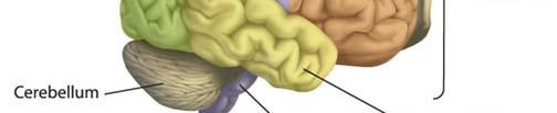
14 Vision Vision is the most important sense in humans Vision includes three steps Data recording and transformation in the retina Data transmission through the optical nerves Data elaboration by the brain 14

15 Natural vision Retina 15
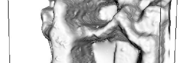
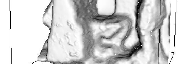
16 Natural vision fmri shows the brain areas interested by neural activity associated to vision Optic chiasm 16
17 Artificial vision Camera = retina Frame grabber = nerves CPU = brain 17
 CMOS (Complementary Metal Oxide Semiconductor")
18 Vision sensors: hardware CCD (Coupled Charge Device, light sensitive, e discharging capacitors of 5 to 25 micron) CMOS (Complementary Metal Oxide Semiconductor technology) 18
 Discretization")

19 Artificial vision Projection from a 3D world on a 2D plane: perspective projection (transform matrix) Discretization effects due to transducer pixels (CCD or CMOS) Misalignment errors Parallel lines Converging lines Pixel discretization 19


20 Artificial vision π π F 3D object π Optical axis Reversed image plane Focal Plane Principal image plane 20
21 Artificial vision Geometric parameters P R Optical axis m x m O m xc Cc R c f x i i i O i x i t c i i i R i j i P Focal plane π F R R i O i j i π Image plane 21
22 Artificial vision R T A R c m P Several rigid and perspective transformations are involved T B R R π R i Rescaling R i Optical correction 22
23 Artificial vision x x x c i c = z = f c z f x c i k c A i c z P z c C c x i x c P π πf C i π P f f 23
24 Artificial vision R i R i x x y y 24
25 Artificial vision Image parameters O i p x j i p y i i t c i i C i j i 25


 that")


26 Artificial vision Aberration types Pincushion distortion i Barrel ldistortioni Radial distortion Non radial distortion (tangential) Radial distortion is modelled by a function D(r) that affects each point v in the projected plane relative to the principal point p, where D(r) is normally a non linear scalar function and p is close to the midpoint of the projected image. Barrel projections are characterized by a positive gradient of the distortion function, whereas pincushion by a negative gradient v = D ( v p ) v + p d 26
27 Artificial vision Image errors Errors are due to the imperfect alignment of pixel elements 27
28 Vision sensors Distance sensors Depth from focus Stereo vision Motion and optical flow 28
29 Depth from focus The method consists in measuring the distance of an object evaluating the focal length adjustment necessary to bring it in focus Short distance focus Medium distance focus Far distance focus 29
30 Depth from focus = + f f D e D L L D (,, xyz) image plane ( x, y ) i i focal plane L ( d + e ) D δ e bx ( ) = 2 f ( d + e) s( x) blur radius shape 30


31 Depth from focus Near focusing Far focusing 31
32 Stereo disparity ( x, y, z) left lens f z x right lens image plane ( x, y ) ( x, y ) r r b baseline (known) 32
33 Stereo disparity Idealized camera geometry for stereo vision x /2 x x + b r x b /2 =, = f z f z x x r b = f z ( x + x )/2 r x = b x x r ( y + y ) r )/2 y = b y y r z b f = x x f ( ) Disparity between two images Depth computation r 33
34 Stereo vision Distance is inversely proportional to disparity closer objects can be measured more accurately Disparity is proportional to baseline For a given disparity error, the accuracy of the depth estimate increases with increasing baseline b However, as b is increased, some objects may appear in one camera, but not in the other A point visible from both cameras produces a conjugate pair Conjugate pairs lie on epipolar line (parallel to the x axis for the arrangement in the figure above) 34
35 Stereo points correspondence These two points are corresponding: how do you find them in the two images? Left image Right image Right Left Disparity 35
36 Epipolar lines P corresponding points stay on the epipolar lines π τ τ 1 2 q q 2 C 1 epipolar lines e 1 Rt, e 2 these two points are known and fixed (they are called epipoles) C 2 36
37 Stereo vision Depth calculation The key problem in stereo vision is how to optimally solve the correspondence problem Corresponding points lie on the epipolar lines Gray Level Matching Match gray level features on corresponding epipolar lines Zero crossing of Laplacian of Gaussians is a widely used approach for identifying the same feature in the left and right images Brightness = image irradiance or intensity I(x,y) is computed and used as shown below 37
38 Laplacian The Laplacian is a 2D isotropic measure of the 2 nd spatial derivative of an image The Laplacian of an image highlights regions of rapid intensity change and is often used for edge detection The Laplacian is often applied to an image that has first been smoothed hdwith ihsomething approximating i a Gaussian smoothing filter, in order to reduce its sensitivity to noise The operator normally takes a single gray level image as input and produces another gray level image as output 38
 is given by: Lxy (, ) I = + x")

39 Laplacian The Laplacian L(x,y) of an image with pixel lintensity it values I(x,y) is given by: Lxy (, ) I = + x L = P I 2 2 I y P = 1 G = Convolution operator P 2 =
40 Convolution Convolution is a simple mathematical operation which is fundamental to many image processing operators Convolution multiplies together two arrays of numbers, generally of different sizes, but of the same dimensionality, to produce a third array of numbers of the same dimensionality This can be used in image processing to implement operators whose output pixel values are simple linear combinations of certain input pixel values In an image processing, one of the input arrays is normally just the gray level image. The second array is usually much smaller, and is also two dimensional (although it may be just a single pixel thick), and is known as the kernel 40
41 Convolution 41
42 Convolution matrix Iij (, ) IMAGE Kij (, ) KERNEL If the image has M rows and N columns, and the kernel has m rows and n columns, then the size of the output image will have M - m + 1 rows, and N - n + 1 columns (6 2+ 1) (9 3+ 1) =
43 Convolution product k11 k12 k13 k21 k22 k23 k11 k12 k13 k21 k22 k23 Oi (, j ) m n Oij (, ) = Ii ( + k 1, j+ l 1) Kkl (, ) k= 1 l= 1 i = 1,, ( M m + 1); j = 1,, ( N n + 1) 43
44 Stereo vision Zero crossing of Laplacian of Gaussian Identification of features that are stable and match well Laplacian of intensity image Step/edge detection of noisy image: filter through Gaussian smoothing 44
45 Edge detection 45


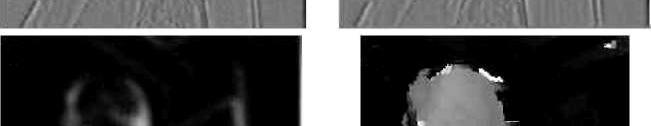
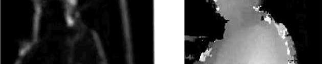
46 Stereo vision L R VERTICAL FILTERED IMAGES Confidence image Depth image 46
47 Optical flow Optical flow or optic flow is the pattern of apparent motion of objects, surfaces, and edges in a visual scene caused by the relative motion between an observer (an eye or a camera) and the scene Optical flow techniques such as motion detection, object segmentation, time to collision and focus of expansion calculations, motion compensated encoding, and stereo disparity measurement utilize this motion of the objects surfaces, and edges 47
48 Optical flow The optical flow methods try to calculate the motion between two image frames which are taken at times t and t + δt at every voxel position. These methods are called differential since they are based on local ltaylor series approximations of the image signal, i.e., they use partial derivatives with respect to the spatial and temporal coordinates Ixyt (,,) = Ix ( + δxy, + δyt, + δt) I I I = Ixyt (,, ) + δ x + δ y + δ t +... x y t I I I δx + δy + δt = x y t 0 Avoxel(volumetric + pixel) is a volume element representing a value on aregular grid in 3D space 48
49 Optical flow I I V + V + I = 0 x y x y t T I V = I t This problem is known as the aperture problem of the optical flow algorithms There is only one equation in two unknowns and therefore cannot be solved To find the optical flow another set of equations is needed, given by some additional constraint. All optical flow methods introduce additional conditions for estimating the actual flow. 49
50 Optical flow Lucas Kanade Optical Flow Method A two-frame differential methods for motion estimation The additional constraints needed for the estimation of the flow are introduced in this method by assuming that the flow V, V is constant x y in a small window of size with m > 1 which is centered at pixel (, xy) 2 Numbering the pixels as a set of equations can be found 1,, n = m I V + I V = I x1 x y1 y t I I I x1 1 t 1 y 1 I V + I V = I I I V I x2 x y2 y t 2 x2 y2 x t2 = V y I V + I V = I I I I xn x yn y t xn yn t n n 1 ( T T Ax = b x = AAA ) Ab 50
Basilio Bona DAUIN Politecnico di Torino
 ROBOTICA 03CFIOR DAUIN Politecnico di Torino Mobile & Service Robotics Sensors for Robotics 3 Laser sensors Rays are transmitted and received coaxially The target is illuminated by collimated rays The
Range Sensors (time of flight) (1)
 (1)") Range Sensors (time of flight) (1) Large range distance measurement -> called range sensors Range information: key element for localization and environment modeling Ultrasonic sensors, infra-red sensors
Range Sensors (time of flight) (1) Large range distance measurement -> called range sensors Range information: key element for localization and environment modeling Ultrasonic sensors, infra-red sensors
10/5/09 1. d = 2. Range Sensors (time of flight) (2) Ultrasonic Sensor (time of flight, sound) (1) Ultrasonic Sensor (time of flight, sound) (2) 4.1.
 (2) Ultrasonic Sensor (time of flight, sound) (1) Ultrasonic Sensor (time of flight, sound) (2) 4.1.") Range Sensors (time of flight) (1) Range Sensors (time of flight) (2) arge range distance measurement -> called range sensors Range information: key element for localization and environment modeling Ultrasonic
Range Sensors (time of flight) (1) Range Sensors (time of flight) (2) arge range distance measurement -> called range sensors Range information: key element for localization and environment modeling Ultrasonic
ROBOTICS 01PEEQW. Basilio Bona DAUIN Politecnico di Torino
 ROBOTICS 01PEEQW DAUIN Politecnico di Torino Mobile & Service Robotics Sensors for Robotics 4 Vision Vision is the most important sense in humans and is becoming important also in robotics not expensive
Complex Sensors: Cameras, Visual Sensing. The Robotics Primer (Ch. 9) ECE 497: Introduction to Mobile Robotics -Visual Sensors
 ECE 497: Introduction to Mobile Robotics -Visual Sensors") Complex Sensors: Cameras, Visual Sensing The Robotics Primer (Ch. 9) Bring your laptop and robot everyday DO NOT unplug the network cables from the desktop computers or the walls Tuesday s Quiz is on Visual
Complex Sensors: Cameras, Visual Sensing The Robotics Primer (Ch. 9) Bring your laptop and robot everyday DO NOT unplug the network cables from the desktop computers or the walls Tuesday s Quiz is on Visual
Depth. Common Classification Tasks. Example: AlexNet. Another Example: Inception. Another Example: Inception. Depth
 Common Classification Tasks Recognition of individual objects/faces Analyze object-specific features (e.g., key points) Train with images from different viewing angles Recognition of object classes Analyze
3D Sensing and Reconstruction Readings: Ch 12: , Ch 13: ,
 3D Sensing and Reconstruction Readings: Ch 12: 12.5-6, Ch 13: 13.1-3, 13.9.4 Perspective Geometry Camera Model Stereo Triangulation 3D Reconstruction by Space Carving 3D Shape from X means getting 3D coordinates
Capturing, Modeling, Rendering 3D Structures
 Computer Vision Approach Capturing, Modeling, Rendering 3D Structures Calculate pixel correspondences and extract geometry Not robust Difficult to acquire illumination effects, e.g. specular highlights
1 (5 max) 2 (10 max) 3 (20 max) 4 (30 max) 5 (10 max) 6 (15 extra max) total (75 max + 15 extra)
 2 (10 max) 3 (20 max) 4 (30 max) 5 (10 max) 6 (15 extra max) total (75 max + 15 extra)") Mierm Exam CS223b Stanford CS223b Computer Vision, Winter 2004 Feb. 18, 2004 Full Name: Email: This exam has 7 pages. Make sure your exam is not missing any sheets, and write your name on every page. The
Mierm Exam CS223b Stanford CS223b Computer Vision, Winter 2004 Feb. 18, 2004 Full Name: Email: This exam has 7 pages. Make sure your exam is not missing any sheets, and write your name on every page. The
3D Sensing. 3D Shape from X. Perspective Geometry. Camera Model. Camera Calibration. General Stereo Triangulation.
 3D Sensing 3D Shape from X Perspective Geometry Camera Model Camera Calibration General Stereo Triangulation 3D Reconstruction 3D Shape from X shading silhouette texture stereo light striping motion mainly
Camera Calibration. Schedule. Jesus J Caban. Note: You have until next Monday to let me know. ! Today:! Camera calibration
 Camera Calibration Jesus J Caban Schedule! Today:! Camera calibration! Wednesday:! Lecture: Motion & Optical Flow! Monday:! Lecture: Medical Imaging! Final presentations:! Nov 29 th : W. Griffin! Dec 1
DD2423 Image Analysis and Computer Vision IMAGE FORMATION. Computational Vision and Active Perception School of Computer Science and Communication
 DD2423 Image Analysis and Computer Vision IMAGE FORMATION Mårten Björkman Computational Vision and Active Perception School of Computer Science and Communication November 8, 2013 1 Image formation Goal:
Stereo imaging ideal geometry
 Stereo imaging ideal geometry (X,Y,Z) Z f (x L,y L ) f (x R,y R ) Optical axes are parallel Optical axes separated by baseline, b. Line connecting lens centers is perpendicular to the optical axis, and
Introduction to Computer Vision. Introduction CMPSCI 591A/691A CMPSCI 570/670. Image Formation
 Introduction CMPSCI 591A/691A CMPSCI 570/670 Image Formation Lecture Outline Light and Optics Pinhole camera model Perspective projection Thin lens model Fundamental equation Distortion: spherical & chromatic
Chapter 2 - Fundamentals. Comunicação Visual Interactiva
 Chapter - Fundamentals Comunicação Visual Interactiva Structure of the human eye (1) CVI Structure of the human eye () Celular structure of the retina. On the right we can see one cone between two groups
EXAM SOLUTIONS. Image Processing and Computer Vision Course 2D1421 Monday, 13 th of March 2006,
 School of Computer Science and Communication, KTH Danica Kragic EXAM SOLUTIONS Image Processing and Computer Vision Course 2D1421 Monday, 13 th of March 2006, 14.00 19.00 Grade table 0-25 U 26-35 3 36-45
MAPI Computer Vision. Multiple View Geometry
 MAPI Computer Vision Multiple View Geometry Geometry o Multiple Views 2- and 3- view geometry p p Kpˆ [ K R t]p Geometry o Multiple Views 2- and 3- view geometry Epipolar Geometry The epipolar geometry
Cameras and Stereo CSE 455. Linda Shapiro
 Cameras and Stereo CSE 455 Linda Shapiro 1 Müller-Lyer Illusion http://www.michaelbach.de/ot/sze_muelue/index.html What do you know about perspective projection? Vertical lines? Other lines? 2 Image formation
Stereo CSE 576. Ali Farhadi. Several slides from Larry Zitnick and Steve Seitz
 Stereo CSE 576 Ali Farhadi Several slides from Larry Zitnick and Steve Seitz Why do we perceive depth? What do humans use as depth cues? Motion Convergence When watching an object close to us, our eyes
Rectification and Distortion Correction
 Rectification and Distortion Correction Hagen Spies March 12, 2003 Computer Vision Laboratory Department of Electrical Engineering Linköping University, Sweden Contents Distortion Correction Rectification
Visual Pathways to the Brain
 Visual Pathways to the Brain 1 Left half of visual field which is imaged on the right half of each retina is transmitted to right half of brain. Vice versa for right half of visual field. From each eye
Stereo. 11/02/2012 CS129, Brown James Hays. Slides by Kristen Grauman
 Stereo 11/02/2012 CS129, Brown James Hays Slides by Kristen Grauman Multiple views Multi-view geometry, matching, invariant features, stereo vision Lowe Hartley and Zisserman Why multiple views? Structure
3D Vision Real Objects, Real Cameras. Chapter 11 (parts of), 12 (parts of) Computerized Image Analysis MN2 Anders Brun,
, 12 (parts of) Computerized Image Analysis MN2 Anders Brun,") 3D Vision Real Objects, Real Cameras Chapter 11 (parts of), 12 (parts of) Computerized Image Analysis MN2 Anders Brun, anders@cb.uu.se 3D Vision! Philisophy! Image formation " The pinhole camera " Projective
3D Vision Real Objects, Real Cameras Chapter 11 (parts of), 12 (parts of) Computerized Image Analysis MN2 Anders Brun, anders@cb.uu.se 3D Vision! Philisophy! Image formation " The pinhole camera " Projective
521466S Machine Vision Exercise #1 Camera models
 52466S Machine Vision Exercise # Camera models. Pinhole camera. The perspective projection equations or a pinhole camera are x n = x c, = y c, where x n = [x n, ] are the normalized image coordinates,
EE795: Computer Vision and Intelligent Systems
 EE795: Computer Vision and Intelligent Systems Spring 2012 TTh 17:30-18:45 FDH 204 Lecture 14 130307 http://www.ee.unlv.edu/~b1morris/ecg795/ 2 Outline Review Stereo Dense Motion Estimation Translational
Midterm Exam Solutions
 Midterm Exam Solutions Computer Vision (J. Košecká) October 27, 2009 HONOR SYSTEM: This examination is strictly individual. You are not allowed to talk, discuss, exchange solutions, etc., with other fellow
Range Imaging Through Triangulation. Range Imaging Through Triangulation. Range Imaging Through Triangulation. Range Imaging Through Triangulation
 Obviously, this is a very slow process and not suitable for dynamic scenes. To speed things up, we can use a laser that projects a vertical line of light onto the scene. This laser rotates around its vertical
Machine vision. Summary # 11: Stereo vision and epipolar geometry. u l = λx. v l = λy
 1 Machine vision Summary # 11: Stereo vision and epipolar geometry STEREO VISION The goal of stereo vision is to use two cameras to capture 3D scenes. There are two important problems in stereo vision:
Rectification and Disparity
 Rectification and Disparity Nassir Navab Slides prepared by Christian Unger What is Stereo Vision? Introduction A technique aimed at inferring dense depth measurements efficiently using two cameras. Wide
Recap: Features and filters. Recap: Grouping & fitting. Now: Multiple views 10/29/2008. Epipolar geometry & stereo vision. Why multiple views?
 Recap: Features and filters Epipolar geometry & stereo vision Tuesday, Oct 21 Kristen Grauman UT-Austin Transforming and describing images; textures, colors, edges Recap: Grouping & fitting Now: Multiple
Chapters 1 5. Photogrammetry: Definition, introduction, and applications. Electro-magnetic radiation Optics Film development and digital cameras
 Chapters 1 5 Chapter 1: Photogrammetry: Definition, introduction, and applications Chapters 2 4: Electro-magnetic radiation Optics Film development and digital cameras Chapter 5: Vertical imagery: Definitions,
Computer Vision Lecture 17
 Computer Vision Lecture 17 Epipolar Geometry & Stereo Basics 13.01.2015 Bastian Leibe RWTH Aachen http://www.vision.rwth-aachen.de leibe@vision.rwth-aachen.de Announcements Seminar in the summer semester
Computer Vision Lecture 17
 Announcements Computer Vision Lecture 17 Epipolar Geometry & Stereo Basics Seminar in the summer semester Current Topics in Computer Vision and Machine Learning Block seminar, presentations in 1 st week
Understanding Variability
 Understanding Variability Why so different? Light and Optics Pinhole camera model Perspective projection Thin lens model Fundamental equation Distortion: spherical & chromatic aberration, radial distortion
Computer Vision. Coordinates. Prof. Flávio Cardeal DECOM / CEFET- MG.
 Computer Vision Coordinates Prof. Flávio Cardeal DECOM / CEFET- MG cardeal@decom.cefetmg.br Abstract This lecture discusses world coordinates and homogeneous coordinates, as well as provides an overview
Chapter 3 Geometric Optics
 Chapter 3 Geometric Optics [Reading assignment: Goodman, Fourier Optics, Appendix B Ray Optics The full three dimensional wave equation is: (3.) One solution is E E o ûe i ωt± k r ( ). This is a plane
Omni Stereo Vision of Cooperative Mobile Robots
 Omni Stereo Vision of Cooperative Mobile Robots Zhigang Zhu*, Jizhong Xiao** *Department of Computer Science **Department of Electrical Engineering The City College of the City University of New York (CUNY)
Stereo Vision. MAN-522 Computer Vision
 Stereo Vision MAN-522 Computer Vision What is the goal of stereo vision? The recovery of the 3D structure of a scene using two or more images of the 3D scene, each acquired from a different viewpoint in
Sensor Modalities. Sensor modality: Different modalities:
 Sensor Modalities Sensor modality: Sensors which measure same form of energy and process it in similar ways Modality refers to the raw input used by the sensors Different modalities: Sound Pressure Temperature
Digital Image Processing COSC 6380/4393
 Digital Image Processing COSC 6380/4393 Lecture 21 Nov 16 th, 2017 Pranav Mantini Ack: Shah. M Image Processing Geometric Transformation Point Operations Filtering (spatial, Frequency) Input Restoration/
Computer Vision 2. SS 18 Dr. Benjamin Guthier Professur für Bildverarbeitung. Computer Vision 2 Dr. Benjamin Guthier
 Computer Vision 2 SS 18 Dr. Benjamin Guthier Professur für Bildverarbeitung Computer Vision 2 Dr. Benjamin Guthier 1. IMAGE PROCESSING Computer Vision 2 Dr. Benjamin Guthier Content of this Chapter Non-linear
Representing the World
 Table of Contents Representing the World...1 Sensory Transducers...1 The Lateral Geniculate Nucleus (LGN)... 2 Areas V1 to V5 the Visual Cortex... 2 Computer Vision... 3 Intensity Images... 3 Image Focusing...
LIGHT & OPTICS. Fundamentals of Physics 2112 Chapter 34 1
 LIGHT & OPTICS Fundamentals of Physics 22 Chapter 34 Chapter 34 Images. Two Types of Images 2. Plane Mirrors 3. Spherical Mirrors 4. Images from Spherical Mirrors 5. Spherical Refracting Surfaces 6. Thin
CSE 4392/5369. Dr. Gian Luca Mariottini, Ph.D.
 University of Texas at Arlington CSE 4392/5369 Introduction to Vision Sensing Dr. Gian Luca Mariottini, Ph.D. Department of Computer Science and Engineering University of Texas at Arlington WEB : http://ranger.uta.edu/~gianluca
Comparison between Motion Analysis and Stereo
 MOTION ESTIMATION The slides are from several sources through James Hays (Brown); Silvio Savarese (U. of Michigan); Octavia Camps (Northeastern); including their own slides. Comparison between Motion Analysis
Computer Vision cmput 428/615
 Computer Vision cmput 428/615 Basic 2D and 3D geometry and Camera models Martin Jagersand The equation of projection Intuitively: How do we develop a consistent mathematical framework for projection calculations?
Massachusetts Institute of Technology Department of Computer Science and Electrical Engineering 6.801/6.866 Machine Vision QUIZ II
 Massachusetts Institute of Technology Department of Computer Science and Electrical Engineering 6.801/6.866 Machine Vision QUIZ II Handed out: 001 Nov. 30th Due on: 001 Dec. 10th Problem 1: (a (b Interior
3D Computer Vision. Depth Cameras. Prof. Didier Stricker. Oliver Wasenmüller
 3D Computer Vision Depth Cameras Prof. Didier Stricker Oliver Wasenmüller Kaiserlautern University http://ags.cs.uni-kl.de/ DFKI Deutsches Forschungszentrum für Künstliche Intelligenz http://av.dfki.de
Final Exam Study Guide
 Final Exam Study Guide Exam Window: 28th April, 12:00am EST to 30th April, 11:59pm EST Description As indicated in class the goal of the exam is to encourage you to review the material from the course.
COSC579: Scene Geometry. Jeremy Bolton, PhD Assistant Teaching Professor
 COSC579: Scene Geometry Jeremy Bolton, PhD Assistant Teaching Professor Overview Linear Algebra Review Homogeneous vs non-homogeneous representations Projections and Transformations Scene Geometry The
CS201 Computer Vision Camera Geometry
 CS201 Computer Vision Camera Geometry John Magee 25 November, 2014 Slides Courtesy of: Diane H. Theriault (deht@bu.edu) Question of the Day: How can we represent the relationships between cameras and the
Chapter 23. Geometrical Optics (lecture 1: mirrors) Dr. Armen Kocharian
 Dr. Armen Kocharian") Chapter 23 Geometrical Optics (lecture 1: mirrors) Dr. Armen Kocharian Reflection and Refraction at a Plane Surface The light radiate from a point object in all directions The light reflected from a plane
Chapter 23 Geometrical Optics (lecture 1: mirrors) Dr. Armen Kocharian Reflection and Refraction at a Plane Surface The light radiate from a point object in all directions The light reflected from a plane
Last update: May 4, Vision. CMSC 421: Chapter 24. CMSC 421: Chapter 24 1
 Last update: May 4, 200 Vision CMSC 42: Chapter 24 CMSC 42: Chapter 24 Outline Perception generally Image formation Early vision 2D D Object recognition CMSC 42: Chapter 24 2 Perception generally Stimulus
STEREO VISION AND LASER STRIPERS FOR THREE-DIMENSIONAL SURFACE MEASUREMENTS
 XVI CONGRESO INTERNACIONAL DE INGENIERÍA GRÁFICA STEREO VISION AND LASER STRIPERS FOR THREE-DIMENSIONAL SURFACE MEASUREMENTS BARONE, Sandro; BRUNO, Andrea University of Pisa Dipartimento di Ingegneria
Correspondence and Stereopsis. Original notes by W. Correa. Figures from [Forsyth & Ponce] and [Trucco & Verri]
![Correspondence and Stereopsis. Original notes by W. Correa. Figures from [Forsyth & Ponce] and [Trucco & Verri]](/thumbs/80/81283374.jpg "Correspondence and Stereopsis. Original notes by W. Correa. Figures from [Forsyth & Ponce] and [Trucco & Verri]") Correspondence and Stereopsis Original notes by W. Correa. Figures from [Forsyth & Ponce] and [Trucco & Verri] Introduction Disparity: Informally: difference between two pictures Allows us to gain a strong
Correspondence and Stereopsis Original notes by W. Correa. Figures from [Forsyth & Ponce] and [Trucco & Verri] Introduction Disparity: Informally: difference between two pictures Allows us to gain a strong
Chapters 1 5. Photogrammetry: Definition, introduction, and applications. Electro-magnetic radiation Optics Film development and digital cameras
 Chapters 1 5 Chapter 1: Photogrammetry: Definition, introduction, and applications Chapters 2 4: Electro-magnetic radiation Optics Film development and digital cameras Chapter 5: Vertical imagery: Definitions,
All human beings desire to know. [...] sight, more than any other senses, gives us knowledge of things and clarifies many differences among them.
![All human beings desire to know. [...] sight, more than any other senses, gives us knowledge of things and clarifies many differences among them.](/thumbs/91/106597332.jpg "All human beings desire to know. [...] sight, more than any other senses, gives us knowledge of things and clarifies many differences among them.") All human beings desire to know. [...] sight, more than any other senses, gives us knowledge of things and clarifies many differences among them. - Aristotle University of Texas at Arlington Introduction
All human beings desire to know. [...] sight, more than any other senses, gives us knowledge of things and clarifies many differences among them. - Aristotle University of Texas at Arlington Introduction
3D Geometry and Camera Calibration
 3D Geometry and Camera Calibration 3D Coordinate Systems Right-handed vs. left-handed x x y z z y 2D Coordinate Systems 3D Geometry Basics y axis up vs. y axis down Origin at center vs. corner Will often
CSE 252B: Computer Vision II
 CSE 252B: Computer Vision II Lecturer: Serge Belongie Scribe: Sameer Agarwal LECTURE 1 Image Formation 1.1. The geometry of image formation We begin by considering the process of image formation when a
Outline The Refraction of Light Forming Images with a Plane Mirror 26-3 Spherical Mirror 26-4 Ray Tracing and the Mirror Equation
 Chapter 6 Geometrical Optics Outline 6-1 The Reflection of Light 6- Forming Images with a Plane Mirror 6-3 Spherical Mirror 6-4 Ray Tracing and the Mirror Equation 6-5 The Refraction of Light 6-6 Ray Tracing
EXAM SOLUTIONS. Computer Vision Course 2D1420 Thursday, 11 th of march 2003,
 Numerical Analysis and Computer Science, KTH Danica Kragic EXAM SOLUTIONS Computer Vision Course 2D1420 Thursday, 11 th of march 2003, 8.00 13.00 Exercise 1 (5*2=10 credits) Answer at most 5 of the following
Depth. Chapter Stereo Imaging
 Chapter 11 Depth Calculating the distance of various points in the scene relative to the position of the camera is one of the important tasks for a computer vision system. A common method for extracting
Matching. Compare region of image to region of image. Today, simplest kind of matching. Intensities similar.
 Matching Compare region of image to region of image. We talked about this for stereo. Important for motion. Epipolar constraint unknown. But motion small. Recognition Find object in image. Recognize object.
THE VIEWING TRANSFORMATION
 ECS 178 Course Notes THE VIEWING TRANSFORMATION Kenneth I. Joy Institute for Data Analysis and Visualization Department of Computer Science University of California, Davis Overview One of the most important
Prof. Fanny Ficuciello Robotics for Bioengineering Visual Servoing
 Visual servoing vision allows a robotic system to obtain geometrical and qualitative information on the surrounding environment high level control motion planning (look-and-move visual grasping) low level
An introduction to 3D image reconstruction and understanding concepts and ideas
 Introduction to 3D image reconstruction An introduction to 3D image reconstruction and understanding concepts and ideas Samuele Carli Martin Hellmich 5 febbraio 2013 1 icsc2013 Carli S. Hellmich M. (CERN)
Outline. ETN-FPI Training School on Plenoptic Sensing
 Outline Introduction Part I: Basics of Mathematical Optimization Linear Least Squares Nonlinear Optimization Part II: Basics of Computer Vision Camera Model Multi-Camera Model Multi-Camera Calibration
ECE-161C Cameras. Nuno Vasconcelos ECE Department, UCSD
 ECE-161C Cameras Nuno Vasconcelos ECE Department, UCSD Image formation all image understanding starts with understanding of image formation: projection of a scene from 3D world into image on 2D plane 2
CV: 3D to 2D mathematics. Perspective transformation; camera calibration; stereo computation; and more
 CV: 3D to 2D mathematics Perspective transformation; camera calibration; stereo computation; and more Roadmap of topics n Review perspective transformation n Camera calibration n Stereo methods n Structured
Dense 3D Reconstruction. Christiano Gava
 Dense 3D Reconstruction Christiano Gava christiano.gava@dfki.de Outline Previous lecture: structure and motion II Structure and motion loop Triangulation Today: dense 3D reconstruction The matching problem
Image Formation. Antonino Furnari. Image Processing Lab Dipartimento di Matematica e Informatica Università degli Studi di Catania
 Image Formation Antonino Furnari Image Processing Lab Dipartimento di Matematica e Informatica Università degli Studi di Catania furnari@dmi.unict.it 18/03/2014 Outline Introduction; Geometric Primitives
Mech 296: Vision for Robotic Applications. Today s Summary
 Mech 296: Vision for Robotic Applications Gravity Probe B http://einstein.stanford.edu/content/pict_gal/main_index.html Lecture 3: Visual Sensing 3.1 Today s Summary 1. Visual Signal: Position in Time
Geometry of Multiple views
 1 Geometry of Multiple views CS 554 Computer Vision Pinar Duygulu Bilkent University 2 Multiple views Despite the wealth of information contained in a a photograph, the depth of a scene point along the
Information page for written examinations at Linköping University TER2
 Information page for written examinations at Linköping University Examination date 2016-08-19 Room (1) TER2 Time 8-12 Course code Exam code Course name Exam name Department Number of questions in the examination
Introduction to 3D Machine Vision
 Introduction to 3D Machine Vision 1 Many methods for 3D machine vision Use Triangulation (Geometry) to Determine the Depth of an Object By Different Methods: Single Line Laser Scan Stereo Triangulation
x 2 + y 2 + z 2 = 1 = ˆr ŷ = ±y cosθ z (a) The half angle of the cones (inside the material) is just given by the critical angle sinθ c n = 3.
 The half angle of the cones (inside the material) is just given by the critical angle sinθ c n = 3.") Exercise.-6 The results of this problem are somewhat general and apply to any rectangular parallelepiped with source located at any position inside. One can see this as follows. The direction of an arbitrary
Exercise.-6 The results of this problem are somewhat general and apply to any rectangular parallelepiped with source located at any position inside. One can see this as follows. The direction of an arbitrary
Practical Robotics (PRAC)
") Practical Robotics (PRAC) A Mobile Robot Navigation System (1) - Sensor and Kinematic Modelling Nick Pears University of York, Department of Computer Science December 17, 2014 nep (UoY CS) PRAC Practical
Practical Robotics (PRAC) A Mobile Robot Navigation System (1) - Sensor and Kinematic Modelling Nick Pears University of York, Department of Computer Science December 17, 2014 nep (UoY CS) PRAC Practical
Motion Analysis. Motion analysis. Now we will talk about. Differential Motion Analysis. Motion analysis. Difference Pictures
 Now we will talk about Motion Analysis Motion analysis Motion analysis is dealing with three main groups of motionrelated problems: Motion detection Moving object detection and location. Derivation of
Measurements using three-dimensional product imaging
 ARCHIVES of FOUNDRY ENGINEERING Published quarterly as the organ of the Foundry Commission of the Polish Academy of Sciences ISSN (1897-3310) Volume 10 Special Issue 3/2010 41 46 7/3 Measurements using
Epipolar Geometry and the Essential Matrix
 Epipolar Geometry and the Essential Matrix Carlo Tomasi The epipolar geometry of a pair of cameras expresses the fundamental relationship between any two corresponding points in the two image planes, and
CS 664 Slides #9 Multi-Camera Geometry. Prof. Dan Huttenlocher Fall 2003
 CS 664 Slides #9 Multi-Camera Geometry Prof. Dan Huttenlocher Fall 2003 Pinhole Camera Geometric model of camera projection Image plane I, which rays intersect Camera center C, through which all rays pass
Flexible Calibration of a Portable Structured Light System through Surface Plane
 Vol. 34, No. 11 ACTA AUTOMATICA SINICA November, 2008 Flexible Calibration of a Portable Structured Light System through Surface Plane GAO Wei 1 WANG Liang 1 HU Zhan-Yi 1 Abstract For a portable structured
Outline. ETN-FPI Training School on Plenoptic Sensing
 Outline Introduction Part I: Basics of Mathematical Optimization Linear Least Squares Nonlinear Optimization Part II: Basics of Computer Vision Camera Model Multi-Camera Model Multi-Camera Calibration
There are many cues in monocular vision which suggests that vision in stereo starts very early from two similar 2D images. Lets see a few...
 STEREO VISION The slides are from several sources through James Hays (Brown); Srinivasa Narasimhan (CMU); Silvio Savarese (U. of Michigan); Bill Freeman and Antonio Torralba (MIT), including their own
L2 Data Acquisition. Mechanical measurement (CMM) Structured light Range images Shape from shading Other methods
 Structured light Range images Shape from shading Other methods") L2 Data Acquisition Mechanical measurement (CMM) Structured light Range images Shape from shading Other methods 1 Coordinate Measurement Machine Touch based Slow Sparse Data Complex planning Accurate 2
L2 Data Acquisition Mechanical measurement (CMM) Structured light Range images Shape from shading Other methods 1 Coordinate Measurement Machine Touch based Slow Sparse Data Complex planning Accurate 2
Today. Stereo (two view) reconstruction. Multiview geometry. Today. Multiview geometry. Computational Photography
 reconstruction. Multiview geometry. Today. Multiview geometry. Computational Photography") Computational Photography Matthias Zwicker University of Bern Fall 2009 Today From 2D to 3D using multiple views Introduction Geometry of two views Stereo matching Other applications Multiview geometry
Computational Photography Matthias Zwicker University of Bern Fall 2009 Today From 2D to 3D using multiple views Introduction Geometry of two views Stereo matching Other applications Multiview geometry
IMPORTANT INSTRUCTIONS
 2017 Imaging Science Ph.D. Qualifying Examination June 9, 2017 9:00AM to 12:00PM IMPORTANT INSTRUCTIONS You must complete two (2) of the three (3) questions given for each of the core graduate classes.
Available online at Procedia Engineering 7 (2010) Procedia Engineering 00 (2010)
 Procedia Engineering 00 (2010)") Available online at www.sciencedirect.com Procedia Engineering 7 (2010) 290 296 Procedia Engineering 00 (2010) 000 000 Procedia Engineering www.elsevier.com/locate/procedia www.elsevier.com/locate/procedia
Available online at www.sciencedirect.com Procedia Engineering 7 (2010) 290 296 Procedia Engineering 00 (2010) 000 000 Procedia Engineering www.elsevier.com/locate/procedia www.elsevier.com/locate/procedia
Super-resolution on Text Image Sequences
 November 4, 2004 Outline Outline Geometric Distortion Optical/Motion Blurring Down-Sampling Total Variation Basic Idea Outline Geometric Distortion Optical/Motion Blurring Down-Sampling No optical/image
Optic Flow and Basics Towards Horn-Schunck 1
 Optic Flow and Basics Towards Horn-Schunck 1 Lecture 7 See Section 4.1 and Beginning of 4.2 in Reinhard Klette: Concise Computer Vision Springer-Verlag, London, 2014 1 See last slide for copyright information.
Edge and local feature detection - 2. Importance of edge detection in computer vision
 Edge and local feature detection Gradient based edge detection Edge detection by function fitting Second derivative edge detectors Edge linking and the construction of the chain graph Edge and local feature
Depth Measurement and 3-D Reconstruction of Multilayered Surfaces by Binocular Stereo Vision with Parallel Axis Symmetry Using Fuzzy
 Depth Measurement and 3-D Reconstruction of Multilayered Surfaces by Binocular Stereo Vision with Parallel Axis Symmetry Using Fuzzy Sharjeel Anwar, Dr. Shoaib, Taosif Iqbal, Mohammad Saqib Mansoor, Zubair
Final Review CMSC 733 Fall 2014
 Final Review CMSC 733 Fall 2014 We have covered a lot of material in this course. One way to organize this material is around a set of key equations and algorithms. You should be familiar with all of these,
MEFT / Quantum Optics and Lasers. Suggested problems from Fundamentals of Photonics Set 1 Gonçalo Figueira
 MEFT / Quantum Optics and Lasers Suggested problems from Fundamentals of Photonics Set Gonçalo Figueira. Ray Optics.-3) Aberration-Free Imaging Surface Determine the equation of a convex aspherical nonspherical)
CS664 Lecture #18: Motion
 CS664 Lecture #18: Motion Announcements Most paper choices were fine Please be sure to email me for approval, if you haven t already This is intended to help you, especially with the final project Use
Dense 3D Reconstruction. Christiano Gava
 Dense 3D Reconstruction Christiano Gava christiano.gava@dfki.de Outline Previous lecture: structure and motion II Structure and motion loop Triangulation Wide baseline matching (SIFT) Today: dense 3D reconstruction
Application questions. Theoretical questions
 The oral exam will last 30 minutes and will consist of one application question followed by two theoretical questions. Please find below a non exhaustive list of possible application questions. The list
Biometrics Technology: Image Processing & Pattern Recognition (by Dr. Dickson Tong)
") Biometrics Technology: Image Processing & Pattern Recognition (by Dr. Dickson Tong) References: [1] http://homepages.inf.ed.ac.uk/rbf/hipr2/index.htm [2] http://www.cs.wisc.edu/~dyer/cs540/notes/vision.html
Biometrics Technology: Image Processing & Pattern Recognition (by Dr. Dickson Tong) References: [1] http://homepages.inf.ed.ac.uk/rbf/hipr2/index.htm [2] http://www.cs.wisc.edu/~dyer/cs540/notes/vision.html
Digital Image Processing COSC 6380/4393
 Digital Image Processing COSC 6380/4393 Lecture 4 Jan. 24 th, 2019 Slides from Dr. Shishir K Shah and Frank (Qingzhong) Liu Digital Image Processing COSC 6380/4393 TA - Office: PGH 231 (Update) Shikha
Computer Vision I. Dense Stereo Correspondences. Anita Sellent 1/15/16
 Computer Vision I Dense Stereo Correspondences Anita Sellent Stereo Two Cameras Overlapping field of view Known transformation between cameras From disparity compute depth [ Bradski, Kaehler: Learning