Introduction to Solid Modeling Parametric Modeling. Mechanical Engineering Dept.
|
|
|
- Dinah Hensley
- 6 years ago
- Views:
Transcription

1 Introduction to Solid Modeling Parametric Modeling 1
2 Why draw 3D Models? 3D models are easier to interpret. Simulation under real-life conditions. Less expensive than building a physical model. 3D models can be used to perform finite element analysis (stress, deflection, thermal..). 3D models can be used directly in manufacturing, Computer Numerical Control (CNC). Can be used for presentations and marketing. 2
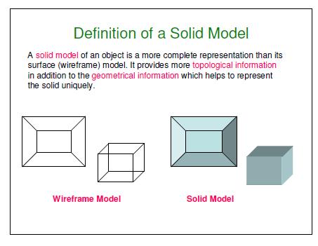
3 3D Modeling There are three basic types of three-dimensional computer geometric modeling methods: Wireframe modeling Surface modeling Solid modeling 3
4 Wireframe Modeling Contains information about the locations of all the points (vertices) and edges in space coordinates. Each vertex is defined by x, y, z coordinate. Edges are defined by a pair of vertices. Faces are defined as three or more edges. Wireframe is a collection of edges, there is no skin defining the area between the edges. 4
5 Wireframe Modeling Advantages: Can quickly and efficiently convey information than multiview drawings. The only lines seen are the intersections of surfaces. Can be used for finite element analysis. Can be used as input for CNC machines to generate simple parts. Contain most of the information needed to create surface, solid and higher order models 5
6 Disadvantages: Wireframe Modeling Do not represent an actual solids (no surface and volume). Cannot model complex curved surfaces. Cannot be used to calculate dynamic properties. Ambiguous views 6
7 Uniqueness problem. Wireframe Modeling 7
8 Surface Modeling A surface model represents the skin of an object, these skins have no thickness or material type. Surface models define the surface features, as well as the edges, of objects. A mathematical function describes the path of a curve (parametric techniques). Surfaces are edited as single entities. 8
9 Advantages: Surface Modeling Eliminates ambiguity and non-uniqueness present in wireframe models by hiding lines not seen. Renders the model for better visualization and presentation, objects appear more realistic. Provides the surface geometry for CNC machining. Provides the geometry needed for mold and die design. Can be used to design and analyze complex free-formed surfaces (ship hulls, airplane fuselages, car bodies, ). Surface properties such as roughness, color and reflectivity can be assigned and demonstrated. 9
10 Surface Modeling Disadvantages: Surface models provide no information about the inside of an object. Complicated computation, depending on the number of surfaces 10
11 Solid Models In the solid modeling, the solid definitions include vertices (nodes), edges, surfaces, weight, and volume. The model is a complete and unambiguous representation of a precisely enclosed and filled volume. Advantages: Has all the advantages of surface models (uniqueness, non-ambiguous, realistic, surface profile) plus volumetric information. Allows the designer to create multiple options for a design. 2D standard drawings, assembly drawing and exploded views are generated form the 3D model. 11
12 Advantages: Solid Models Can easily be exported to different Finite Element Methods programs for analysis. Can be used in newly manufacturing techniques; computer integrated manufacturing (CIM), computer aided manufacturing (CAM) and design for manufacturability ans assembly (DFM, DFA) Mass and volumetric properties of an object can be easily obtained; total mass, mass center, area and mass moment of inertia, volume, radius of gyration, 12
13 Volumetric and Mass properties of an object can be easily obtained. Corresponding mass properties are obtained if density is included. 13
14 Solid Models Disadvantages: More intensive computation than wireframe and surface modeling. Requires more powerful computers (faster with more memory and good graphics), not a problem any more. 14
15 15
16 16
17 17
18 18
19 19
20 20
21 21
22 22
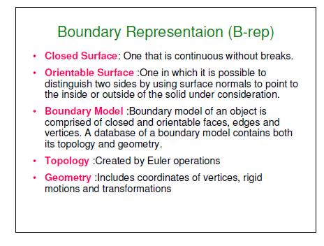
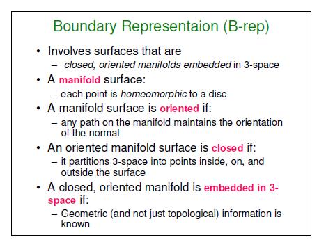
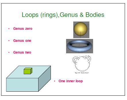
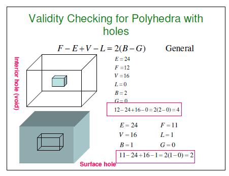
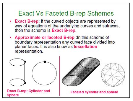
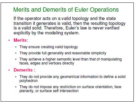
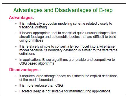
23 Solid Modeling Boundary Representation (B-rep) A solid model is formed by defining the surfaces that form its boundary (edges and surfaces) The face of a B-rep represents an oriented surface, there are two sides to the surface; solid side (inside) and void side (outside), unlike faces in a wireframe. B-rep model is created using Euler operation Many Finite Element Method (FEM) programs use this method. Allows the interior meshing of the volume to be more easily controlled. 23
24 B-Rep Data Structure 24
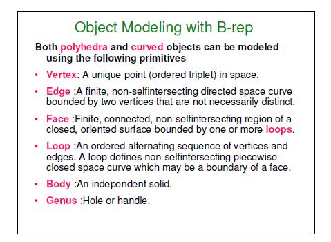
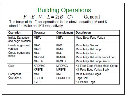
25 Euler Operators Geometric entities stored in B-Rep data structures are the shell, face, loop, edge, and vertex. Operators are needed to manipulate these entities (e.g., an operator to make an edge, an operator to delete an edge, ) 25
26 26
27 27
28 28
29 29
30 30
31 31
32 32
33 33
34 34
35 35
36 36
37 37
38 38
39 39
40 40
41 41
42 42
43 43
44 44
45 45
46 46
47 47
48 48
49 Constructive Solid Geometry, CSG CSG defines a model in terms of combining basic and generated (using extrusion and sweeping operation) solid shapes. CSG uses Boolean operations to construct a model (George Boole, , invented Boolean algebra). There are three basic Boolean operations: Union (Unite, join) - the operation combines two volumes included in the different solids into a single solid. Subtract (cut) - the operation subtracts the volume of one solid from the other solid object. Intersection - the operation keeps only the volume common to both solids 49

50 Primitive Solids and Boolean Operations The basic primitive solid: 50
51 Primitive Solids The location of the insertion base or base point and default axes orientation. 51
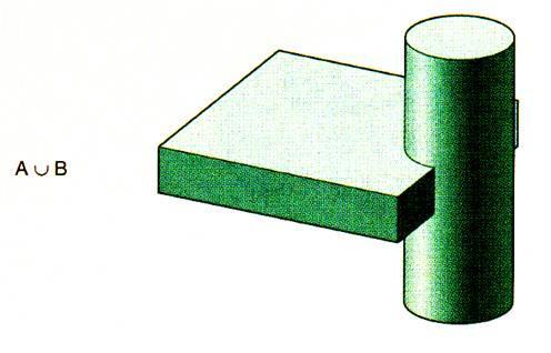
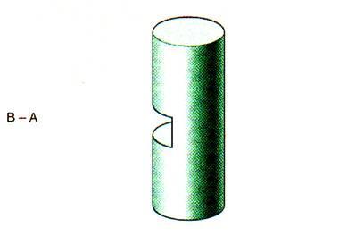
52 Boolean Operations Subtract Union Intersection 52
53 Implementing Boolean Operation Consider solids A and B. 53
54 Boolean Operation The intersection curves of all the faces of solid A and B are calculated. These intersections are inscribed on the associated faces of the two solids. 54
55 Boolean Operation The faces of solid A are classified according to their relative location with respect to solid B. Each face is tested to determine whether it is located inside, outside, or on the boundary surface of solid B. The faces in group A 1 are outside solid B, and those of group B 1 are inside solid A. 55
56 Boolean Operation Groups of faces are collected according to the specific Boolean operation and the unnecessary face groups are eliminated. For example, for union operation, group A 1 and B 2 are collected and A 2 and B 1 are eliminated. 56
57 Boolean Operation The two solids are glued at their common boundary. 57


58 Solid Modeling Example Using CSG Union Plan your modeling strategy before you start creating the solid model Cut Cut 58
59 Creating Solid Models Parametric Modeling Concept Parametric is a term used to describe a dimension s ability to change the shape of model geometry if the dimension value is modified. Feature-based is a term used to describe the various components of a model. For example, a part can consists of various types of features such as holes, grooves, fillets, and chamfers. Parametric modeler are featured-based, parametric, solid modeling design program: SolidWorks, Pro- Engineer, Unigraphics (CSG and parametric),.. 59
60 Design Intent In parametric modeling, dimensions control the model. Design intent is how your model will react when dimension values are changed. 60
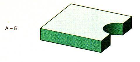
61 Example: Design Intent The drawing shows the intent of the designer that the inclined plane (chamfer) should have a flat area measuring 2.5 inches and that it should start at a point 1.25 inches from the base of the drawing. These parameters are what the designer deemed significant for this model Remember that the placement of dimensions is very important because they are being used to drive the shape of the geometry. If the 2.5 in. vertical dimension increases, the 2.5 in. flat across the chamfer will be maintained, but its angle will change. 61
62 Design Intent In this drawing, what is important to the designer is the vertical location and horizontal dimension of the chamfer, rather than the flat of the chamfer In the last drawing, the designer calls for a specific angle for the chamfer. In this case the angle of the chamfer should be dimensioned O
63 Design Intent 63
64 Design Notes Keep in mind that dimensioning scheme can be changed at any time. You are not locked into a specific design. You can also design without dimensioning, rough out a sketch, and then later go back and fully define it. Do not be concerned with dimensioning to datum or stacked tolerances in the part. Those issues can be addressed in the drawing layout. Be more concerned with your design intent. 64
65 Boolean Versus Parametric Modeling The ability to go back on some earlier stage in the design process and make changes by editing a sketch or changing some dimensions is extremely important to a designer. This is the main advantage of a parametric (SolidWorks, Unigraphics, Inventor, Pro-Engineer) over a non-parametric modeler (AutoCAD 3D modeler Boolean operation) 65
66 Example: Boolean Versus Parametric Modeling Let s assume that it is desired to design a part consisting of a ring with a certain thickness and a series of counterbore holes along the perimeter. 66
67 Boolean Versus Parametric Modeling Boolean operation Make the base part by creating two cylinders and subtract the small one from the large one Create the solid geometry that will become the counterbore holes and generate the pattern. 67

68 Boolean Versus Parametric Modeling Position the pattern about the perimeter of the base part. Locating the holes is critical to creating an accurate solid model. Subtract the pattern from the base part to create the actual holes. What would happen if you had to come back to this part to change the thickness of the ring or size of the counterbore holes? Since Boolean operation was used to create the part, changing the thickness would not increase the height of the holes. There is no association between the thickness and the hole pattern location. 68
69 Boolean Versus Parametric Modeling Parametric modeling (SolidWorks, ProE, UG, ) Create the initial base, the ring, by extruding the profile (circles) in a particular direction (Pro/E or SolidWorks) or use primitive solids and Boolean operation (UG). Create the counterbore as a feature. Select the top surface of the ring and either sketch the two holes and extrude at different depth or use the hole feature option. 69
70 Boolean Versus Parametric Modeling The next step would be to pattern the hole. The pattern would actually be considered a feature in itself, and would have its set of parametric variables, such as the number of copies and the angle between copies. The model created would be identical to the one created using Boolean operation, but with intelligence built into the model. 70
71 Boolean Versus Parametric Modeling The true power of parametric modeling shines through when design changes need to be made. The design modification is made by simply changing a dimension. Since the counterbore is associated with the top surface of the ring, any changes in the thickness of the ring would automatically be reflected on the counterbore depth. 71
72 Sketching and Features When discussing the mind-set needed for working with parametric modelers, there are two topics that need to be expanded: Sketching and Features Sketching Take the word sketch literally. A sketch should be just that, a sketch. When sketching, it is not necessary to create geometry with accuracy. Lines, arcs, and additional geometry need not be created with exact dimensions in mind. When the dimensions are added, the sketch will change size and shape. This is the essence of Parametric Modeling. In short, the sketch need only be the approximate size and shape of the part being designed. When dimensions and constraints are added, they will drive the size and the shape of the geometry. 72


73 Features Sketched Feature Sketching and Features Create a 2D sketch. Create a feature from the sketch by extruding, revolving, sweeping, lofting and blending Revolved feature Extruded feature 73
74 Creating Features from Sketches 74

75 Applied Feature Sketching and Features Applied feature does not require a sketch. They are applied directly to the model. Fillets and chamfers are very common applied features. Chamfer Fillet 75
76 Summary Solid Modeling Methods Primitive creation modeling A solid model is created by retrieving primitive solids and performing Boolean operations Sweeping function Creates a solid by translating, revolving or sweeping a predefined 2D shape (Sketching). If geometric and dimensional constraints are imposed, it is called Parametric Modeling. Feature-based Modeling Models a solid by using familiar shapes; holes, slots, grooves, pockets, chamfers, fillets.. 76
77 Summary Solid Modeling Methods Modifying functions Rounding (or blending) and lifting. Boundary Modeling Lower entities of a solid (vertices, edges and faces) are directly manipulated. 77
78 Sketching Take the word sketch literally. A sketch should be just that, a sketch. Sketches are able to capture the designer s intent for the part like no other technique. The sketch is the best tool for creating solids because of flexibility in shapes and the ability to edit. Ideal for creating unusual freeform shapes. 78
79 Sketching A sketch is a set of two dimensional curves joined in a string that when swept or extruded forms a solid body. When sketching it is not necessary to create geometry with accuracy. Lines, arcs, and additional geometry need not be created with exact dimensions in mind. 79
80 Sketching When the dimensions are added, the sketch will change size and shape. This is the essence of parametric modeling In short, the sketch need only be the approximate size and shape of the part being designed. The geometric constraints and dimensions, when added, will drive the size and the shape of the geometry. Curves are parametrically associated to each other and the solid that is created by them. 80
Introduction to Solid Modeling
 Introduction to Solid Modeling Parametric Modeling 1 Why draw 3D Models? 3D models are easier to interpret. 3D models can be used to perform engineering analysis, finite element analysis (stress, deflection,
Geometric Modeling. Introduction
 Geometric Modeling Introduction Geometric modeling is as important to CAD as governing equilibrium equations to classical engineering fields as mechanics and thermal fluids. intelligent decision on the
Geometric Modeling. Creating 3D solid geometry in a computer! MAE 455 Computer-Aided Design and Drafting
 Geometric Modeling Creating 3D solid geometry in a computer! Partial History of Geometric Modeling 1963 Wireframe Computer Graphics Invented (Ivan Sutherland, MIT) 2 Partial History 1964 DAC-1, General
Feature-Based Modeling and Optional Advanced Modeling. ENGR 1182 SolidWorks 05
 Feature-Based Modeling and Optional Advanced Modeling ENGR 1182 SolidWorks 05 Today s Objectives Feature-Based Modeling (comprised of 2 sections as shown below) 1. Breaking it down into features Creating
Geometric Modeling. Creating 3D solid geometry in a computer! Partial History of Geometric Modeling
 Geometric Modeling Creating 3D solid geometry in a computer! Partial History of Geometric Modeling 1963 Wireframe Computer Graphics Invented (Ivan Sutherland, MIT) 2 1 Partial History 1964 DAC-1, General
Geometric Modeling Lecture Series. Prof. G. Wang Department of Mechanical and Industrial Engineering University of Manitoba
 Geometric Modeling 25.353 Lecture Series Prof. G. Wang Department of Mechanical and Industrial Engineering University of Manitoba Introduction Geometric modeling is as important to CAD as governing equilibrium
Autodesk Conceptual Design Curriculum 2011 Student Workbook Unit 2: Parametric Exploration Lesson 1: Parametric Modeling
 Autodesk Conceptual Design Curriculum 2011 Student Workbook Unit 2: Parametric Exploration Lesson 1: Parametric Modeling Overview: Parametric Modeling In this lesson, you learn the basic principles of
L1 - Introduction. Contents. Introduction of CAD/CAM system Components of CAD/CAM systems Basic concepts of graphics programming
 L1 - Introduction Contents Introduction of CAD/CAM system Components of CAD/CAM systems Basic concepts of graphics programming 1 Definitions Computer-Aided Design (CAD) The technology concerned with the
3D Modeling and Design Glossary - Beginner
 3D Modeling and Design Glossary - Beginner Align: to place or arrange (things) in a straight line. To use the Align tool, select at least two objects by Shift left-clicking on them or by dragging a box
Solid Modeling: Part 1
 Solid Modeling: Part 1 Basics of Revolving, Extruding, and Boolean Operations Revolving Exercise: Stepped Shaft Start AutoCAD and use the solid.dwt template file to create a new drawing. Create the top
Autodesk Inventor 2019 and Engineering Graphics
 Autodesk Inventor 2019 and Engineering Graphics An Integrated Approach Randy H. Shih SDC PUBLICATIONS Better Textbooks. Lower Prices. www.sdcpublications.com Powered by TCPDF (www.tcpdf.org) Visit the
Chapter 9 3D Modeling
 Chapter 9 3D Modeling Copyright The McGraw-Hill Companies, Inc. Permission required for reproduction or display. 3D Modeling Snapshot Since Mid 1980 s become common place in industry Software Types Wireframe
Geometric Modeling Systems
 Geometric Modeling Systems Wireframe Modeling use lines/curves and points for 2D or 3D largely replaced by surface and solid models Surface Modeling wireframe information plus surface definitions supports
VALLIAMMAI ENGINEERING COLLEGE
 VALLIAMMAI ENGINEERING COLLEGE SRM Nagar, Kattankulathur 603 203 DEPARTMENT OF MECHANICAL ENGINEERING QUESTION BANK M.E: CAD/CAM I SEMESTER ED5151 COMPUTER APPLICATIONS IN DESIGN Regulation 2017 Academic
3D Design with 123D Design
 3D Design with 123D Design Introduction: 3D Design involves thinking and creating in 3 dimensions. x, y and z axis Working with 123D Design 123D Design is a 3D design software package from Autodesk. A
3. Preprocessing of ABAQUS/CAE
 3.1 Create new model database 3. Preprocessing of ABAQUS/CAE A finite element analysis in ABAQUS/CAE starts from create new model database in the toolbar. Then save it with a name user defined. To build
SOLIDWORKS 2016 and Engineering Graphics
 SOLIDWORKS 2016 and Engineering Graphics An Integrated Approach Randy H. Shih SDC PUBLICATIONS Better Textbooks. Lower Prices. www.sdcpublications.com Powered by TCPDF (www.tcpdf.org) Visit the following
Additional Exercises. You will perform the following exercises to practice the concepts learnt in this course:
 Additional Exercises You will perform the following exercises to practice the concepts learnt in this course: Master Exercise : Mobile Phone Plastic Bottle Exercise 1 Master Exercise : Mobile Phone In
Version 4.1 Demo. RecurDynTM 2002 RecurDyn User Conference
 Version 4.1 Demo RecurDynTM 2002 RecurDyn User Conference What s New? Using Parasolid Kernel Solid Modeler Other Program Interfaces New Data Structure New & Improved Features What s New? Using Parasolid
Creo for Analyst. Overview
 Creo for Analyst Overview In this course, you will learn how to utilize the core functionality enhancements in Creo Parametric 2.0. First, you will become familiar with using and customizing the new ribbon
2D CAD. Courseware Issued: DURATION: 64 hrs
 2D CAD Introduction File management Orthographic drawings View management Display management Layer management Selection methods Parametric drawings Symbol creation using block BOM / Joinery details creation
CAD/CAM COURSE TOPIC OF DISCUSSION GEOMETRIC MODELING DAWOOD COLLEGE OF ENGINEERING & TECHNOLOGY- KARACHI- ENGR. ASSAD ANIS 4/16/2011 1
 CAD/CAM COURSE TOPIC OF DISCUSSION GEOMETRIC MODELING 1 CAD attempts to eliminate the need of developing a prototype for testing and optimizing the design CAD evaluates a design using a model with geometric
SolidWorks 2013 and Engineering Graphics
 SolidWorks 2013 and Engineering Graphics An Integrated Approach Randy H. Shih SDC PUBLICATIONS Schroff Development Corporation Better Textbooks. Lower Prices. www.sdcpublications.com Visit the following
PARAMETRIC MODELING FOR MECHANICAL COMPONENTS 1
 PARAMETRIC MODELING FOR MECHANICAL COMPONENTS 1 Wawre S.S. Abstract: parametric modeling is a technique to generalize specific solid model. This generalization of the solid model is used to automate modeling
SEOUL NATIONAL UNIVERSITY
 Fashion Technology 5. 3D Garment CAD-1 Sungmin Kim SEOUL NATIONAL UNIVERSITY Overview Design Process Concept Design Scalable vector graphics Feature-based design Pattern Design 2D Parametric design 3D
Chapter 12 Solid Modeling. Disadvantages of wireframe representations
 Chapter 12 Solid Modeling Wireframe, surface, solid modeling Solid modeling gives a complete and unambiguous definition of an object, describing not only the shape of the boundaries but also the object
6. CAD SOFTWARE. CAD is a really useful tool for every engineer, and especially for all the designers.
 6. CAD SOFTWARE CAD is a really useful tool for every engineer, and especially for all the designers. Not only because it makes drawing easier, but because it presents the advantage that if any detail
Pro/ENGINEER Concepts
 1 Pro/ENGINEER Concepts Becoming a Pro/ENGINEER user means learning to think in terms of how the components of a design interact, and to think ahead to how those interactions may change. At the simplest
Live Classroom Curriculum Guide
 Curriculum Guide Live Classroom Curriculum Guide Milling using Pro/ENGINEER Wildfire 4.0 Pro/ENGINEER Mechanica Simulation using Pro/ENGINEER Wildfire 4.0 Introduction to Pro/ENGINEER Wildfire 4.0 Pro/ENGINEER
SOLIDWORKS 2016: A Power Guide for Beginners and Intermediate Users
 SOLIDWORKS 2016: A Power Guide for Beginners and Intermediate Users The premium provider of learning products and solutions www.cadartifex.com Table of Contents Dedication... 3 Preface... 15 Part 1. Introducing
Engineering designs today are frequently
 Basic CAD Engineering designs today are frequently constructed as mathematical solid models instead of solely as 2D drawings. A solid model is one that represents a shape as a 3D object having mass properties.
Computer Aided Engineering Applications
 Computer Aided Engineering Applications 1A.Geometric Modeling 1.1 Geometric modelling methods 1.2 Data representation 1.3 Modeling functions 1.4 Structure of a CAD system Engi 6928 - Fall 2014 1.Geometric
COMPUTER AIDED ARCHITECTURAL GRAPHICS FFD 201/Fall 2013 HAND OUT 1 : INTRODUCTION TO 3D
 COMPUTER AIDED ARCHITECTURAL GRAPHICS FFD 201/Fall 2013 INSTRUCTORS E-MAIL ADDRESS OFFICE HOURS Özgür Genca ozgurgenca@gmail.com part time Tuba Doğu tubadogu@gmail.com part time Şebnem Yanç Demirkan sebnem.demirkan@gmail.com
Parametric Modeling with UGS NX 4
 Parametric Modeling with UGS NX 4 Randy H. Shih Oregon Institute of Technology SDC PUBLICATIONS Schroff Development Corporation www.schroff.com www.schroff-europe.com 2-1 Chapter 2 Parametric Modeling
Model data extraction. Mass property data. Mass property data. Mass property data. Integral Processes. Units and volume
 Model data extraction Most solid modelers permit information to be extracted directly from the model database. Graphic profile data 2D drawings annotation Solid model database details the distribution
Create Complex Surfaces
 Create Complex Surfaces In this lesson, you will be introduced to the functionalities available in the Generative Surface Design workbench. Lesson content: Case Study: Surface Design Design Intent Stages
Curriculum Guide. Creo 4.0
 Curriculum Guide Creo 4.0 Live Classroom Curriculum Guide Update to Creo Parametric 4.0 from Creo Parametric 3.0 Introduction to Creo Parametric 4.0 Advanced Modeling using Creo Parametric 4.0 Advanced
Lesson 5 Solid Modeling - Constructive Solid Geometry
 AutoCAD 2000i Tutorial 5-1 Lesson 5 Solid Modeling - Constructive Solid Geometry Understand the Constructive Solid Geometry Concept. Create a Binary Tree. Understand the basic Boolean Operations. Create
Exercise Guide. Published: August MecSoft Corpotation
 VisualCAD Exercise Guide Published: August 2018 MecSoft Corpotation Copyright 1998-2018 VisualCAD 2018 Exercise Guide by Mecsoft Corporation User Notes: Contents 2 Table of Contents About this Guide 4
A Comprehensive Introduction to SolidWorks 2011
 A Comprehensive Introduction to SolidWorks 2011 Godfrey Onwubolu, Ph.D. SDC PUBLICATIONS www.sdcpublications.com Schroff Development Corporation Chapter 2 Geometric Construction Tools Objectives: When
Engineering Drawing II
 Instructional Unit Basic Shading and Rendering -Basic Shading -Students will be able -Demonstrate the ability Class Discussions 3.1.12.B, -Basic Rendering to shade a 3D model to apply shading to a 3D 3.2.12.C,
Technical Education Services
 Autodesk Fusion 360: Introduction to Parametric Modeling Course Length: 3 days Official Training Guide The Autodesk Fusion 360 Introduction to Parametric Modeling training course provides you with an understanding
Creo 3.0. Curriculum Guide
 Creo 3.0 Curriculum Guide Live Classroom Curriculum Guide Update to Creo Parametric 3.0 from Creo Parametric 2.0 Introduction to Creo Parametric 3.0 Advanced Modeling using Creo Parametric 3.0 Advanced
Modeling 3D Objects: Part 2
 Modeling 3D Objects: Part 2 Patches, NURBS, Solids Modeling, Spatial Subdivisioning, and Implicit Functions 3D Computer Graphics by Alan Watt Third Edition, Pearson Education Limited, 2000 General Modeling
Chapter 4 Feature Design Tree
 4-1 Chapter 4 Feature Design Tree Understand Feature Interactions Use the FeatureManager Design Tree Modify and Update Feature Dimensions Perform History-Based Part Modifications Change the Names of Created
Creo 2.0. Curriculum Guide
 Creo 2.0 Curriculum Guide Live Classroom Curriculum Guide Update to Creo Parametric 2.0 from Creo Elements/Pro 5.0 Update to Creo Parametric 2.0 from Pro/ENGINEER Wildfire 4.0 Introduction to Creo Parametric
Education Curriculum Surface Design Specialist
 Education Curriculum Surface Design Specialist Invest your time in imagining next generation designs. Here s what we will teach you to give shape to your imagination. CATIA Surface Design Specialist CATIA
Module 1: Basics of Solids Modeling with SolidWorks
 Module 1: Basics of Solids Modeling with SolidWorks Introduction SolidWorks is the state of the art in computer-aided design (CAD). SolidWorks represents an object in a virtual environment just as it exists
Course Modules for CATIA V6 2013x Essentials for New Users Training Online:
 Course Modules for CATIA V6 2013x - 100 Essentials for New Users Training Online: 1 Launching CATIA V6 The PLM Story Import IGI Models (Essentials) Launching CATIA V6 Choosing a Security Context 2 V6 Navigation
Geometry Definition in the ADINA User Interface (AUI) Daniel Jose Payen, Ph.D. March 7, 2016
 Daniel Jose Payen, Ph.D. March 7, 2016") Geometry Definition in the ADINA User Interface (AUI) Daniel Jose Payen, Ph.D. March 7, 2016 ADINA R&D, Inc., 2016 1 Topics Presented ADINA에서쓰이는 Geometry 종류 Simple (AUI) geometry ADINA-M geometry ADINA-M
Geometry Definition in the ADINA User Interface (AUI) Daniel Jose Payen, Ph.D. March 7, 2016 ADINA R&D, Inc., 2016 1 Topics Presented ADINA에서쓰이는 Geometry 종류 Simple (AUI) geometry ADINA-M geometry ADINA-M
Chapter 2 Parametric Modeling Fundamentals
 2-1 Chapter 2 Parametric Modeling Fundamentals Create Simple Extruded Solid Models Understand the Basic Parametric Modeling Procedure Create 2-D Sketches Understand the "Shape before Size" Approach Use
Autodesk 123D Beta5 Overview
 Autodesk 123D Beta5 Overview Welcome. This overview document for Autodesk 123D will assist you in developing your understanding of the software and how you can use it to create your design ideas. Designing
CATIA Surface Design
 CATIA V5 Training Exercises CATIA Surface Design Version 5 Release 19 September 2008 EDU_CAT_EN_GS1_FX_V5R19 Table of Contents (1/2) Creating Wireframe Geometry: Recap Exercises 4 Creating Wireframe Geometry:
AutoCAD 2013 Tutorial - Second Level: 3D Modeling
 AutoCAD 2013 Tutorial - Second Level: 3D Modeling Randy H. Shih SDC PUBLICATIONS Schroff Development Corporation Better Textbooks. Lower Prices. www.sdcpublications.com Visit the following websites to
Autodesk Inventor 2016
 Parametric Modeling with Autodesk Inventor 2016 Randy H. Shih SDC PUBLICATIONS Better Textbooks. Lower Prices. www.sdcpublications.com Powered by TCPDF (www.tcpdf.org) Visit the following websites to learn
SpaceClaim Professional The Natural 3D Design System. Advanced Technology
 SpaceClaim Professional The Natural 3D Design System SpaceClaim Professional is the 3D productivity tool for engineers who contribute to the design and manufacture of mechanical products across a broad
Autodesk Inventor 2018
 Parametric Modeling with Autodesk Inventor 2018 NEW Contains a new chapter on 3D printing Randy H. Shih SDC PUBLICATIONS Better Textbooks. Lower Prices. www.sdcpublications.com Powered by TCPDF (www.tcpdf.org)
Tutorial Second Level
 AutoCAD 2018 Tutorial Second Level 3D Modeling Randy H. Shih SDC PUBLICATIONS Better Textbooks. Lower Prices. www.sdcpublications.com Powered by TCPDF (www.tcpdf.org) Visit the following websites to learn
Complex Shapes Creation with Hybrid Modelling
 Complex Shapes Creation with Hybrid Modelling Peter De Strijker Technical Sales Executive MFG - Benelux Our Customer s Industries Discrete product manufacture Agenda Quality Analyses of sketches and surfaces
CATIA V5 Parametric Surface Modeling
 CATIA V5 Parametric Surface Modeling Version 5 Release 16 A- 1 Toolbars in A B A. Wireframe: Create 3D curves / lines/ points/ plane B. Surfaces: Create surfaces C. Operations: Join surfaces, Split & Trim
Structural & Thermal Analysis Using the ANSYS Workbench Release 12.1 Environment
 ANSYS Workbench Tutorial Structural & Thermal Analysis Using the ANSYS Workbench Release 12.1 Environment Kent L. Lawrence Mechanical and Aerospace Engineering University of Texas at Arlington SDC PUBLICATIONS
Reconstruction of 3D Interacting Solids of Revolution from 2D Orthographic Views
 Reconstruction of 3D Interacting Solids of Revolution from 2D Orthographic Views Hanmin Lee, Soonhung Han Department of Mechanical Engeneering Korea Advanced Institute of Science & Technology 373-1, Guseong-Dong,
Lecture 4b. Surface. Lecture 3 1
 Lecture 4b Surface Lecture 3 1 Surface More complete and less ambiguous representation than its wireframe representation Can be considered as extension to wireframe representation In finite element, surface
An Overview of Pro/ENGINEER
 An Overview of Pro/ENGINEER The Foundation of Pro/ENGINEER What is Pro/ENGINEER? Pro/ENGINEER is a computer graphics system for modeling various mechanical designs and for performing related design and
Licom Systems Ltd., Training Course Notes. 3D Surface Creation
 , Training Course Notes Work Volume and Work Planes...........................1 Overview..........................................1 Work Volume....................................1 Work Plane......................................1
Live Classroom Curriculum Guide
 Curriculum Guide Live Classroom Curriculum Guide Creo Elements/Pro 5.0 (formerly Pro/ENGINEER Wildfire 5.0) Update from Pro/ENGINEER Wildfire 4.0 Creo Elements/Pro 5.0 (formerly Pro/ENGINEER Wildfire 5.0)
Autodesk Inventor 6 Essentials Instructor Guide Chapter Four: Creating Placed Features Chapter Outline This chapter provides instruction on the follow
 Chapter Four: Creating Placed Features Chapter Outline This chapter provides instruction on the following topics and provides exercises for students to practice their skills. Day Two Topic: How to create
Autodesk Inventor Design Exercise 2: F1 Team Challenge Car Developed by Tim Varner Synergis Technologies
 Autodesk Inventor Design Exercise 2: F1 Team Challenge Car Developed by Tim Varner Synergis Technologies Tim Varner - 2004 The Inventor User Interface Command Panel Lists the commands that are currently
Parametric Modeling. With. Autodesk Inventor. Randy H. Shih. Oregon Institute of Technology SDC PUBLICATIONS
 Parametric Modeling With Autodesk Inventor R10 Randy H. Shih Oregon Institute of Technology SDC PUBLICATIONS Schroff Development Corporation www.schroff.com www.schroff-europe.com 2-1 Chapter 2 Parametric
Chapter 1. SolidWorks Overview
 Chapter 1 SolidWorks Overview Objectives: When you complete this chapter you will: Have a good background knowledge of SolidWorks Have learnt how to start a SolidWorks session Understand the SolidWorks
Parametric Modeling with NX 12
 Parametric Modeling with NX 12 NEW Contains a new chapter on 3D printing Randy H. Shih SDC PUBLICATIONS Better Textbooks. Lower Prices. www.sdcpublications.com Powered by TCPDF (www.tcpdf.org) Visit the
Lecture 4, 5/27/2017, Rhino Interface an overview
 數字建築與城市设计 Spring 2017 Lecture 4, 5/27/2017, Rhino Interface an overview Copyright 2017, Chiu-Shui Chan. All Rights Reserved. This lecture concentrates on the use of tools, 3D solid modeling and editing
BobCAD CAM V25 4 Axis Standard Posted by Al /09/20 22:03
 BobCAD CAM V25 4 Axis Standard Posted by Al - 2012/09/20 22:03 Many BobCAD CAM clients that run a 4 axis have requested to work directly with Solids or STL files. In the past we only offered 4 axis indexing
Mechanical Design V5R19 Update
 CATIA V5 Training Foils Mechanical Design V5R19 Update Version 5 Release 19 August 2008 EDU_CAT_EN_MD2_UF_V5R19 1 About this course Objectives of the course Upon completion of this course you will be able
Solid Modeling. Ron Goldman Department of Computer Science Rice University
 Solid Modeling Ron Goldman Department of Computer Science Rice University Solids Definition 1. A model which has a well defined inside and outside. 2. For each point, we can in principle determine whether
Chapter 2 Parametric Modeling Fundamentals
 2-1 Chapter 2 Parametric Modeling Fundamentals Create Simple Extruded Solid Models Understand the Basic Parametric Modeling Procedure Create 2-D Sketches Understand the Shape before Size Approach Use the
Structural & Thermal Analysis using the ANSYS Workbench Release 11.0 Environment. Kent L. Lawrence
 ANSYS Workbench Tutorial Structural & Thermal Analysis using the ANSYS Workbench Release 11.0 Environment Kent L. Lawrence Mechanical and Aerospace Engineering University of Texas at Arlington SDC PUBLICATIONS
3 AXIS STANDARD CAD. BobCAD-CAM Version 28 Training Workbook 3 Axis Standard CAD
 3 AXIS STANDARD CAD This tutorial explains how to create the CAD model for the Mill 3 Axis Standard demonstration file. The design process includes using the Shape Library and other wireframe functions
Solid Modeling Lecture Series. Prof. Gary Wang Department of Mechanical and Manufacturing Engineering The University of Manitoba
 Solid Modeling 25.353 Lecture Series Prof. Gary Wang Department of Mechanical and Manufacturing Engineering The University of Manitoba Information complete, unambiguous, accurate solid model Solid Modeling
Autodesk AutoCAD In Mechanical Engineering Design Edward Locke
 Autodesk AutoCAD In Mechanical Engineering Design Edward Locke Engineering Department Santa Ana College Mechanical Engineering Drafting Essentials Working Drawings: Orthographic Projection Views (multi-view,
Pro/ENGINEER Wildfire 3.0 Curriculum Guide
 Pro/ENGINEER Wildfire 3.0 Curriculum Guide NOTE: For a graphical depiction of the curriculum based on job role, please visit this page: http://www.ptc.com/services/edserv/learning/paths/ptc/proe_wf3.htm
Solid Problem Ten. In this chapter, you will learn the following to World Class standards:
 C h a p t e r 11 Solid Problem Ten In this chapter, you will learn the following to World Class standards: 1. Sketch of Solid Problem Ten 2. Starting a 3D Part Drawing 3. Modifying How the UCS Icon is
3D Modeling. Visualization Chapter 4. Exercises
 Three-dimensional (3D) modeling software is becoming more prevalent in the world of engineering design, thanks to faster computers and better software. Two-dimensional (2D) multiview drawings made using
Introduction to ANSYS DesignModeler
 Lecture 5 Modeling 14. 5 Release Introduction to ANSYS DesignModeler 2012 ANSYS, Inc. November 20, 2012 1 Release 14.5 Preprocessing Workflow Geometry Creation OR Geometry Import Geometry Operations Meshing
4) Finish the spline here. To complete the spline, double click the last point or select the spline tool again.
 Finish the spline here. To complete the spline, double click the last point or select the spline tool again.") 1) Select the line tool 3) Move the cursor along the X direction (be careful to stay on the X axis alignment so that the line is perpendicular) and click for the second point of the line. Type 0.5 for
1) Select the line tool 3) Move the cursor along the X direction (be careful to stay on the X axis alignment so that the line is perpendicular) and click for the second point of the line. Type 0.5 for
December 3, :30 to 5:30 pm. Speaker Name: Tom Short, P.E. Course Title: Taking A Step Into The World Of 3D
 Las Vegas, Nevada December 3, 2002 1:30 to 5:30 pm Speaker Name: Tom Short, P.E. Course Title: Taking A Step Into The World Of 3D Course ID: GD122 Course Outline: Are you an experienced AutoCAD 2D user
Module 2 Review. Assemblies and Rendering. Why Use Assemblies. Assemblies - Key Concepts. Sketch Planes Sketched Features.
 Module 2 Review Assemblies and Rendering EF 101 Modules 3.1, 3.2 Sketch Planes Sketched Features Extrude, Revolve Placed Features Hole, Fillet, Chamfer, Shell, Rect. Pattern Drawing Views Base, Ortho,
Surfacing using Creo Parametric 3.0
 Surfacing using Creo Parametric 3.0 Overview Course Code Course Length TRN-4506-T 3 Days In this course, you will learn how to use various techniques to create complex surfaces with tangent and curvature
CHAPTER 6 THE SUITES VECTOR DRAWING SUITE
 CHAPTER 6 THE SUITES There are two additional tool bar suites for Project Designer sold separately as add-on modules. These are the Vector Drawing Suite, and the Pattern Modeling Suite. This section will
I-deas NX Series Master Modeler Foundation capabilities for feature-based variational solid modeling
 I-deas Series Master Modeler Foundation capabilities for feature-based variational solid modeling fact sheet www.ugs.com Summary I-deas Series Master Modeler is the core design module for the I-deas product
Solid Bodies and Disjointed Bodies
 Solid Bodies and Disjointed Bodies Generally speaking when modelling in Solid Works each Part file will contain single solid object. As you are modelling, each feature is merged or joined to the previous
Feature-based CAM software for mills, multi-tasking lathes and wire EDM. Getting Started
 Feature-based CAM software for mills, multi-tasking lathes and wire EDM www.featurecam.com Getting Started FeatureCAM 2015 R3 Getting Started FeatureCAM Copyright 1995-2015 Delcam Ltd. All rights reserved.
Lesson 3: Surface Creation
 Lesson 3: Surface Creation In this lesson, you will learn how to create surfaces from wireframes. Lesson Contents: Case Study: Surface Creation Design Intent Stages in the Process Choice of Surface Sweeping
GDL Toolbox 2 Reference Manual
 Reference Manual Archi-data Ltd. Copyright 2002. New Features Reference Manual New Save GDL command Selected GDL Toolbox elements can be exported into simple GDL scripts. During the export process, the
SWITCHING FROM SKETCHUP TO VECTORWORKS
 SWITCHING FROM SKETCHUP TO VECTORWORKS INTRODUCTION There are a lot of 3D modeling software programs to choose from and each has its own strengths and weaknesses. For architects, flexibility and ease of
A PARAMETRIC MODELING TECHNIQUES FOR AIRCRAFT STRUCTURES. Elizabeth K Frey The Boeing Company St. Louis, MO
 A99924727 99-1363 PARAMETRC MODELNG TECHNQUES FOR ARCRAFT STRUCTURES Elizabeth K Frey The Boeing Company St. Louis, MO Abstract Parametric solid modeling is a powerful tool that has helped to reduce design
Solids as point set. Solid models. Solid representation schemes (cont d) Solid representation schemes. Solid representation schemes (cont d)
 Solid representation schemes. Solid representation schemes (cont d)") Solid models Solid models developed to address limitations of wireframe modeling. Attempt was to create systems which create only complete representations. Modelers would support direct creation of 3D
Solid models Solid models developed to address limitations of wireframe modeling. Attempt was to create systems which create only complete representations. Modelers would support direct creation of 3D
TRAINING GUIDE SOLIDS-LESSON-3
 TRAINING GUIDE SOLIDS-LESSON-3 Mastercam Training Guide Objectives You will generate the solid model from the existing 2-dimensional geometry. This Lesson covers the following topics: Open an existing
Using 3D AutoCAD Surfaces to Create Composite Solids
 Using 3D AutoCAD Surfaces to Create Composite Solids J.D. Mather Pennsylvania College of Technology GD211-2P This class explores the creation of 3D surfaces used in creating composite solids. Many solid
Lesson 4: Surface Re-limitation and Connection
 Lesson 4: Surface Re-limitation and Connection In this lesson you will learn how to limit the surfaces and form connection between the surfaces. Lesson contents: Case Study: Surface Re-limitation and Connection