Power Rail Overhead Line. Håkan Norling - Professional Services Richard W. Bradshaw Development Date
|
|
|
- Theodore Clarke
- 5 years ago
- Views:
Transcription


1 Power Rail Overhead Line Håkan Norling - Professional Services Richard W. Bradshaw Development Date
2 Power Rail Overhead Line A product for the modeling of overhead lines for electrified railways, build on top of Power Rail Track technology and Power Platform. 2

3 Command Set Network Model View Design Equipment And Rail Track commands for Viewing Reviews Drafting / Plan & Profile Generator 3
4 Network Model A link / node geometric model based upon Power Rail Track geometric entities 4

5 Network Model An overhead line seed database Components, Assemblies & Equipment A network model is created from Rail Track geometry Horizontal Vertical Cant Turnouts Creates a.nwm,.ohl &.ols All tied together! 5
6 Do I really need vertical & cant alignments? No, but If you want to create wire runs then you should have vertical and cant geometry Contact wire is positioned normal to track plane, so it depends on cant If you want to create structures and sub-structures then you should have vertical and cant geometry 6

7 Update Network Model Primarily minor horizontal changes Radii changes Spiral lengths Moving tangents Add / updates to active vertical alignment Add / updates to active cant alignment Unlike Rail Track, we only use the active alignments Updates to crossovers / turnouts Always investigate the details on the results dialog and the dirty graphics! (new!) 7
8 When the geometry changes, keep in mind Update Network Model will be okay if you are looking at: Minor changes in a horizontal alignment Minor changes in a vertical alignment Minor changes in a cant alignment As always, you need to review / check and edit to ensure that you are getting what you are expecting! Update Network Model may not be okay if you are looking at: Additional turnouts and crossovers have been added and you have created a user defined path through a crossover 8
9 Design Commands A set of commands for creation and editing of an overhead line model (i.e. reference lines, overlaps, wire runs and structures) 9


10 Zones & Surfaces A zone is an area where you can not place overhead line structures A road crossing A utility crossing Other objects that you need to avoid Uses a selection set if defined (new!) Or just digitize a shape A surface is an obstruction, like a bridge above the track, where a wire run may need to be lowered to provide clearance between the wire and the structure. Utilizes a terrain model for elevations or height above alignment 10

11 Design Rules Defined in an.xml file, which is user configurable and schema verified at start-up! One or more catenary systems 11

12 Overlaps & Reference Lines Overlaps are where wire runs go in and out of service, one wire ends and a new wire starts Reference lines are working lines upon which wire runs and structures will be placed Placement is based upon design rules for a specific catenary system Look up tables Up to 4 overlap tables (new!) Lines could be 3 spans Arcs could be 5 spans User defined algorithms 12


13 Reference Line Placement Place Multiples Up-station Down-station (new!) Place Single Single station Two points From graphics Can be placed skewed (new!) Can be placed beyond the end of an alignment (new!) 13
14 Reference Line Classifications New will honor the left & right extensions in Options Existing will use what ever you define! Structures will be placed at the reference line ends! 14


15 Turnout Reference Lines Place reference lines relative to a turnout Uses look tables related to the turnout s style User define lengths Note the style sheet with the.xdr! 15

16 Reference Line Editing Adjustment of reference lines Adjusting span lengths Normally by small amounts Updates entire model Reference lines Overlaps Wire Runs Jumpers Structures Other wires And all annotation Extend & Trim Reference Lines 16
 Droppers (optional) (new!) Depends upon active vertical and cant alignments!")
17 Wire Runs Wire runs consist of Contact wire Carrier wire (optional) (new!) Droppers (optional) (new!) Depends upon active vertical and cant alignments! Utilizes design rules 17
18 User Defined Paths User defined paths are used to create wire-runs through a crossover Ideally these are created after you have trimmed / extended reference lines, so that you don t select a user path And after the track geometry has stopped moving (i.e. the track designer is not adding or deleting cross-overs!) Paths can be transposed (new!) Based upon how the first path is selected and added to the user path Also, remember to check on Ignore Overlaps, Create Single Wire Run on Create Wire Runs 18


19 Height & Stagger Height will adjust the vertical position of the wires Stagger will adjust the horizontal position of wires Wires going in and out of service Survive reference line edits! Add and Delete Contact Points (new!) Survive reference line edits! 19

20 Wire Gradient Used to transition the contact and carrier wire from the normal height to a height exception, say transitioning under a bridge 20

 Assemblies (i.e. 3d cells of poles, cantilevers, etc.")
21 Structures Utilizes equipment defined as templates in the data base Select by template type (new!) Single track Multiple track Allows for better organization! Templates Components (i.e. Nuts, bolts, brackets ) Assemblies (i.e. 3d cells of poles, cantilevers, etc.) 21

 Does not use reference lines!")
22 Wire Tensioning / Substructures Requires structures (i.e. end wire and mid wire structures are a child of the structure) Does not use reference lines! Can be placed beyond alignment! 22

23 Naming Utility Naming of Zones Surfaces Reference Lines Overlaps Wire Runs Structures Schemes for Sweden, UK and a generic / no frills scheme Other Wires Jumpers Span Equipment 25
24 View and Reviewing Commands A set of commands for plan, profile and cross section viewing and reporting 26
25 Viewing Plan Reference lines, overlaps, wire runs, structures and substructures Profile Wire runs & design checks Cross Sections Structures 27


26 Plan Viewing Lots of new items! Thank the America users! Stagger cell, versine arc, exceedence (new!) 28


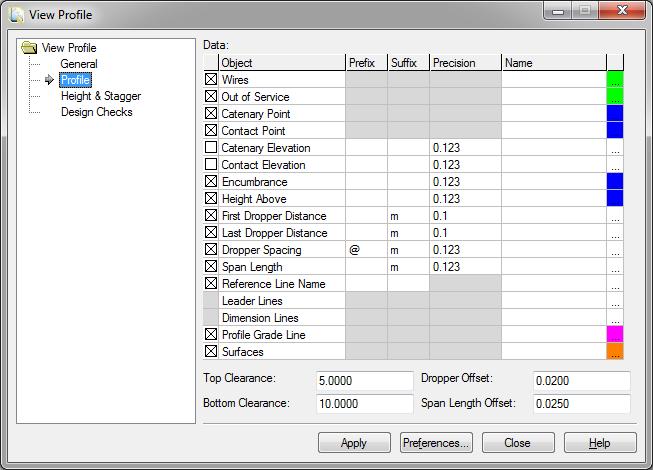

27 Profile Viewing 29
28 Cross Sections Graphical data and Non-graphic data 30


29 Reporting As always XML / XSL based Exceedence reporting (new!) 31


30 Review Network Model Quick snap shot of everything in the model Right click over object and Fit Also, all graphics have tool-tips 32
31 Equipment Commands A set of commands for the creation and editing of components, assemblies, hierarchies and templates 33
32 Equipment Components (i.e. nuts and bolts) Assemblies (i.e. cantilevers) 3D Cells Hierarchies Templates 34


33 Components Non-graphic data Nuts, bolts, etc. Materials 35


34 Assemblies Adds intelligence to cells Attachments Attributes Components 36

35 Templates Combines components and assemblies Assigns attachment points Assigns constraints Optional equipment 37
36 How to get a return on my investment? Lets look at what return is possible based upon various levels of investment 38


37 How to get a return on my investment? Starting with Rail Track geometry Horizontal, Vertical, Cant and Turnouts Design rules At least one catenary system 39
38 By creating reference lines & zones, you get Valid span lengths & wire run lengths Valid overlap span lengths Valid turnout span lengths All based upon design rules for a specific catenary system Interference checking (i.e. zones) Interactive reference line editing, which allows for layout optimization Plan Display & Annotation Reporting 40
39 By creating wire runs, you get Valid contact wire positions Add jumpers and span equipment Plan Display & Annotation Profile Display & Annotation Including design checking Axial forces, mid-span encumbrance, wind blow off, etc. as defined by the design rules Height & Stagger Isolation / clearance checking Reporting Span lengths, wire lengths, droppers, gradients, minimum & maximum exceedence for span lengths and wire heights, etc. 41
40 By adding structures, you get 3D Model Includes structures, mid wire & end wire tensioning, post restraints Plan Display & Annotation Cross Section Display & Annotation Reporting Geometry Quantities Components Assemblies 42
41 And finally a short demo 43
Bentleyuser.dk Årsmøde 2012 Nordic Civil Bentley Civil Workshop
 Bentleyuser.dk Årsmøde 2012 Nordic Civil 2012 Bentley Civil Workshop X09 Power Railtrack Presented by: Richard Bradshaw, BSW Development, Civil Design This page left intentionally blank. Workshop: - X09
TerraScan Tool Guide
 TerraScan Main Toolbox General Toolbar Draw Toolbar Groups Toolbar Vectorize Towers Toolbar Road Toolbar Buildings Toolbar Building Edges Toolbar View Laser Toolbar Model Toolbar Vectorize Wires Toolbar
Bentleyuser.dk Årsmøde 2012 Nordic Civil 2012
 Bentleyuser.dk Årsmøde 2012 Nordic Civil 2012 5.-7. November 2012, Munkebjerg Hotel, Vejle Workshop X13 Advanced Geometrical Layout for Compound and Reversed Curves Team Leader: Richard Bradshaw Bentley
Roadway Alignments and Profiles
 NOTES Module 15 Roadway Alignments and Profiles In this module, you learn how to create horizontal alignments, surface profiles, layout (design) profiles, and profile views in AutoCAD Civil 3D. This module
Working with Plan Production ObjectsChapter1:
 Chapter 1 Working with Plan Production ObjectsChapter1: The lessons in this chapter guide you through the processes of creating and working with plan production objects. Plan production objects include
Alignments CHAPTER INTRODUCTION OBJECTIVES
 CHAPTER 5 Alignments INTRODUCTION This and the next four chapters focus on roadway design and its documentation. This chapter concentrates on roadway plan design. The next three chapters focus on the roadway
Civil 3D Introduction
 Civil 3D Introduction Points Overview Points are data collected by surveyors which represent existing site conditions (elevations, boundaries, utilities, etc.). Each point is numbered (or named) and has
Smart-N Module Standards
 Smart-N Module Standards Current as of June 8, 2014 1. Basic Information 1.1. What is Smart-N? Smart-N ("Smart" stands for "Smaller Modules Are Readily Transportable") is an N-scale modular layout standard.
Organizing Design Data
 Organizing Design Data Module Overview This module explains how to use the data in different files for reference purposes. Module Prerequisites Knowledge of MicroStation s interface Some knowledge about
Design and Optimization of Overhead Transmission Lines using PLS-CADD Software. Course Outline
 Design and Optimization of Overhead Transmission Lines using PLS-CADD Software Course Outline DAYS 1-4: PLS-CADD Beginners Introductions Overview of PLS software PLS Transmission Structure Programs overview
Reaping the Benefits of Migrating to Autodesk Building Systems
 Intro. 1 BD23-3 Reaping the Benefits of Migrating to Autodesk Building Systems Presenter(s) Daryl Bookout & Mike Kotanian Standards Annotation Existing Symbology Content Creation Labels Display Configurations
Autodesk Revit Structure Autodesk
 Autodesk Revit Structure 2011 What s New Top Features Autodesk Revit Structure 2011 Software Enhanced Design Features Fit and Finish Slanted columns Beam systems and trusses Concrete clean-up Concrete
Bentley ConceptStation Workshop 2017 FLUG Spring Training Event
 Bentley ConceptStation Workshop 2017 FLUG Spring Training Event 430 - QuickStart using OpenRoads ConceptStation Bentley Systems, Incorporated 685 Stockton Drive Exton, PA 19341 www.bentley.com Practice
NCDOT Civil Geometry for GEOPAK Users
 2018 NCDOT Civil Geometry for GEOPAK Users Oak Thammavong NCDOT Roadway Design Unit 7/31/2018 This page left intentionally blank Copyright 2018 NCDOT DO NOT DISTRIBUTE Printing for student use is permitted
Cables have been used in the design
 L A B 14 SUSPENSION BRIDGES Parabolas Cables have been used in the design of many different types of structures. They have been used in the design of suspension bridges such as New York s Verrazano Narrows
Introduction to Autodesk Revit Structure
 11/30/2005-5:00 pm - 6:30 pm Room:N. Hemispheres (Salon E2) (Dolphin) Walt Disney World Swan and Dolphin Resort Orlando, Florida Nicolas Mangon - Autodesk SD35-1 This year, Autodesk is introducing the
Autodesk Inventor 6 Essentials Instructor Guide Chapter Four: Creating Placed Features Chapter Outline This chapter provides instruction on the follow
 Chapter Four: Creating Placed Features Chapter Outline This chapter provides instruction on the following topics and provides exercises for students to practice their skills. Day Two Topic: How to create
Pipe Networks CHAPTER INTRODUCTION OBJECTIVES
 CHAPTER 11 Pipe Networks INTRODUCTION Pipe networks are integral to a site-design solution. The piping system s complexity can vary from simple culverts to several storm and sanitary networks that service
Bentley OpenRoads Workshop 2017 FLUG Fall Training Event
 Bentley OpenRoads Workshop 2017 FLUG Fall Training Event F-2P - QuickStart for Roadway Modeling in OpenRoads Technology Bentley Systems, Incorporated 685 Stockton Drive Exton, PA 19341 www.bentley.com
Creating Page Layouts 25 min
 1 of 10 09/11/2011 19:08 Home > Design Tips > Creating Page Layouts Creating Page Layouts 25 min Effective document design depends on a clear visual structure that conveys and complements the main message.
InRoads File Types. Below is a list of the primary file types used for InRoads in the road design process.
 Section 6 InRoads Basic File Types Retrieving InRoads Base Files Internal Naming Convention Alignment Styles and Surface Styles Alignment Point Abbreviations Feature Naming Conventions Project Defaults
SpaceClaim Professional The Natural 3D Design System. Advanced Technology
 SpaceClaim Professional The Natural 3D Design System SpaceClaim Professional is the 3D productivity tool for engineers who contribute to the design and manufacture of mechanical products across a broad
Auto Rotisserie Plans
 Auto Rotisserie Plans Matt & Suzie Kline Owners Red Wing Steel Works 1526 South Park St. Red Wing, MN 55066 USA Phone: 612-584-9353 Email: redwingsteelworks@gmail.com Website: http://redwingsteelworksplans.com
Point Cloud Classification
 Point Cloud Classification Introduction VRMesh provides a powerful point cloud classification and feature extraction solution. It automatically classifies vegetation, building roofs, and ground points.
Civil Update - Whats new in the latest product release
 Civil Update - Whats new in the latest product release Presented by: Ian Rosam, Director Civil Product Management, Bentley Systems, Inc. 1 WWW.BENTLEY.COM 2017 Bentley Systems, Incorporated 2017 Bentley
Publication Number spse01695
 XpresRoute (tubing) Publication Number spse01695 XpresRoute (tubing) Publication Number spse01695 Proprietary and restricted rights notice This software and related documentation are proprietary to Siemens
Solid Edge Drafting. Paul Abbott. SOLID EDGE UNIVERSITY UK 2015 Design Without Boundaries #SEU15UK
 Paul Abbott Solid Edge Drafting Solid Edge University UK 2015 July 8 th, Silverstone UTC SOLID EDGE UNIVERSITY UK 2015 Design Without Boundaries Introduction Page 2 Agenda Quick Look Topics Dimension and
Moving to Altium Designer from Pads Logic and PADS Layout
 Moving to Altium Designer from Pads Logic and PADS Layout Old Content - visit altium.com/documentation Modified by on 13-Sep-2017 Translating complete PADS Logic and PADS Layout designs, including PCB,
Civil 3-D PROFILE CREATION
 Civil 3-D PROFILE CREATION 1 Alignment Overview: As in previous CAD versions, an alignment is a line that describes where you intend the centerline of your planned work to be. That s all. But, in Civil
Helios 3D TM Product Sheet
 Introduction HELIOS 3D is one of the most powerful layout tools for utility scale solar plants available on the market. It is successfully production proven worldwide for nearly 3 years. Furthermore several
Document id Title Organisation /Author Date Status P6 IFC Schema Extension MSG / Thomas Liebich Final
 Document id Title Organisation /Author Date Status P6 IFC Schema Extension MSG / Thomas Liebich 11.12.2014 Final IFC Alignment Schema This document describes the necessary extensions of IFC to implement
Electrical 3D Design & Documentation
 Electrical 3D Design & Documentation Page 1 Overview Conventions User Tasks Using Electrical 3D Design & Documentation Entering the Electrical Assembly Design Workbench Entering the Electrical Part Design
CATIA V5-6R2015 Product Enhancement Overview
 Click to edit Master title style CATIA V5-6R2015 Product Enhancement Overview John Montoya, PLM Technical Support March 2015 1 2010 Inceptra LLC. All rights reserved. Overview of Enhanced Products Overview
Leveraging 2D Data in 3D Modeling
 Leveraging D Data in 3D Modeling Leveraging D Data in 3D Modeling As more and more companies switch to 3D modeling the question of utilizing existing D data and referenced D data from collaborative sources
Performance Components VE 2012 User Guide
 www.iesve.com Integrated Environmental Solutions Limited Developers of the IES Virtual Environment June 2012 Contents 1 - Introduction... 3 2 - Importing components from library... 4 2.1 Accessing the
8 Things you could not do with V8i you can now do with CONNECT Edition
 8 Things you could not do with V8i you can now do with CONNECT Edition MicroStation CONNECT Edition brings a huge number of new productivity tools. Here are a few. By Dan Raker, ConnectPress CONNECT Edition
Autodesk Revit Architecture Training Course Outlines
 Autodesk Revit Architecture Training Course Outlines Description Duration 8 Days (5 classroom + 3 online) The aim of the Autodesk Revit Architecture Professional course is to teach delegates the principles
604 - Drafting in Solid Edge: A Hands-on Experience
 4 th Generation VLC courtesy of Edison2 604 - Drafting in Solid Edge: A Hands-on Experience Steve Webb, Solid Edge Field Support, #SEU13 Agenda: 604 - Drafting in Solid Edge: A Hands-on Experience Who
Module 1: Basics of Solids Modeling with SolidWorks
 Module 1: Basics of Solids Modeling with SolidWorks Introduction SolidWorks is the state of the art in computer-aided design (CAD). SolidWorks represents an object in a virtual environment just as it exists
Ferrovia. BIM-Ready Railway Design Solution. by CGS Labs. Professional software solutions for Civil Engineering. (C) 2017 by CGS Labs
 2017 by CGS Labs") Ferrovia by CGS Labs BIM-Ready Railway Design Solution Professional software solutions for Civil Engineering (C) 2017 by CGS Labs Solution for Railway Design & Rail track Analysis Ferrovia is a professional,
Ferrovia by CGS Labs BIM-Ready Railway Design Solution Professional software solutions for Civil Engineering (C) 2017 by CGS Labs Solution for Railway Design & Rail track Analysis Ferrovia is a professional,
Analysis Steps 1. Start Abaqus and choose to create a new model database
 Source: Online tutorials for ABAQUS Problem Description The two dimensional bridge structure, which consists of steel T sections (b=0.25, h=0.25, I=0.125, t f =t w =0.05), is simply supported at its lower
What's New in NX 11 for Design Engineering
 What's New in NX 11 for Design Engineering NX 11 for Design Productivity Convergent Modeling Many industries use scanned 3D data as part of their design processes. If you have worked with this data in
Seamless Repeat. User Guide
 User Guide Contents 1. Introduction...3 2. One-up document...5 3. Seamless Repeat document...6 4. From a one-up document to a seamless document...9 4.1 Non-seamless...9 4.2 Seamless...10 5. From a Seamless
What's New or Changed in Bentley InRoads XM Edition
 08.09.02.13 Adds to 08.09.01.45 New General Enhancements File Added support for running Inroads Group within MicroStation on a 64 bit operating system. Running Inroads Group within AutoCAD on a 64 bit
Grading and Volumes CHAPTER INTRODUCTION OBJECTIVES
 CHAPTER 10 Grading and Volumes INTRODUCTION AutoCAD Civil 3D uses surface breaklines, cogo points, contours, feature lines, and grading objects to create a surface design. There are numerous ways to grade
ABES. Company Presentation. May ABES Pircher & Partner GmbH Research & Development
 IT Pircher & Partner GmbH Research & Development Company Presentation May 2015 What we do is an independent software house. offers specialised solutions for bridge engineers. geodes/geocon/assemcon support
Introduction to SolidWorks Basics Materials Tech. Wood
 Introduction to SolidWorks Basics Materials Tech. Wood Table of Contents Table of Contents... 1 Book End... 2 Introduction... 2 Learning Intentions... 2 Modelling the Base... 3 Modelling the Front... 10
Constraint Based Modeling Geometric and Dimensional. ENGR 1182 SolidWorks 03
 Constraint Based Modeling Geometric and Dimensional ENGR 1182 SolidWorks 03 Today s Objectives Using two different type of constraints in SolidWorks: Geometric Dimensional SW03 In-Class Activity List Geometric
Let s see the use of each option available under create feature line window:
 FEATURE LINE: Feature line is a kind of a line or an object which we can use as a base line or foot print of grading object. In civil 3d if you want use grading tool you have some kind of base or foot
ADAPT-Builder. Toolbar Descriptions Updated November Copyright All rights reserved 2017
 ADAPT-Builder Toolbar Descriptions Updated November 2017 Copyright All rights reserved 2017 Main Toolbar The Main Toolbar is where the typical functions that are in most programs such as New, Open, Save,
Practice Workbook. Pad and Parking Lot Modeling
 Practice Workbook This workbook is designed for use in Live instructor-led training and for OnDemand selfstudy. The explanations and demonstrations are provided by the instructor in the classroom, or in
Brady Workstation. Simple. Efficient. Flexible.
 Brady Workstation Simple. Efficient. Flexible. Brady Workstation Get more done faster with simple labeling software apps. he latest in label creation software, Brady Workstation has revolutionized how
Assembly Modeling & Assembling Parts
 This week you will learn assembly modeling & assembling parts. The steps to follow are: Assembly modeling Assembly hierarchy Assembly constraints Configurations Assembly strategy 1 Creating Assembly Components
Publication Number spse01695
 XpresRoute (tubing) Publication Number spse01695 XpresRoute (tubing) Publication Number spse01695 Proprietary and restricted rights notice This software and related documentation are proprietary to Siemens
Bentley Civil Workshop
 Bentley Civil Workshop 2015 Spring NCLUG Conference Workshop 32B Using Point Clouds in Civil Workflows Team Leader: Bob Rolle Team Members: Bentley Systems, Incorporated 685 Stockton Drive Exton, PA 19341
Version 13 - UK Edition. Revit family creation standards
 Version 13 - UK Edition Revit family creation standards bimstore bible (Version 13) by bimstore Created August 2015 Printed August 2015 copyright bimstore 2015 All rights reserved No part of this publication
Performance Components
 Performance Components User Guide IES Virtual Environment Copyright 2015 Integrated Environmental Solutions Limited. All rights reserved. No part of the manual is to be copied or reproduced in any form
Module 5: Creating Sheet Metal Transition Piece Between a Square Tube and a Rectangular Tube with Triangulation
 1 Module 5: Creating Sheet Metal Transition Piece Between a Square Tube and a Rectangular Tube with Triangulation In Module 5, we will learn how to create a 3D folded model of a sheet metal transition
SIEMENS. Modeling assemblies. Self-Paced Training. spse01540
 SIEMENS Modeling assemblies Self-Paced Training spse01540 Proprietary and restricted rights notice This software and related documentation are proprietary to Siemens Product Lifecycle Management Software
MAE 455 COMPUTER-AIDED DESIGN AND DRAFTING MIDTERM EXAM PRACTICE QUESTIONS. Name: You are allowed one sheet of notes.
 47 MAE 455 COMPUTER-AIDED DESIGN AND DRAFTING MIDTERM EXAM PRACTICE QUESTIONS Name: You are allowed one sheet of notes. 1. What constraints could be added to fully constrain the wireframe shown? Include
OpenRoads Creating Subsurface Utility Models
 OpenRoads Creating Subsurface Utility Models Existing and Proposed Utilities Presenter: Robert Garrett, PE Bentley Systems, Incorporated 685 Stockton Drive Exton, PA 19341 www.bentley.com Before you Begin:...
LOGIC RAIL. Block Animator. Application Note: BLMA signal bridge. Introduction
 LOGIC RAIL TM "Sophisticated Model Railroad TECHNOLOGIES Electronics" PMB #287 Phone: (281) 251-5813 21175 Tomball Pkwy email: info@logicrailtech.com Houston, TX 77070 http://www.logicrailtech.com Block
3DReshaper Help DReshaper Beginner's Guide. Surveying
 3DReshaper Beginner's Guide Surveying 1 of 29 Cross sections Exercise: Tunnel analysis Surface analysis Exercise: Complete analysis of a concrete floor Surveying extraction Exercise: Automatic extraction
T A B L E O F C O N T E N T S
 T A B L E O F C O N T E N T S UNIT 1: INTRODUCTION... 1 BESIDE STORAGE REFERENCE MANUAL FOR CANVAS... 1 CANVAS DISCLAIMER... 1 BESIDE STORAGE EXTENSION TAB... 1 MAIN SECTIONS OF THE BESIDE STORAGE TAB...
To Bentley Select customers. Preferences for InRoads Group V8.11 (SS2)
") bentleyuser.dk To Bentley Select customers C/O Bentley Scandinavia A/S Gydevang 39-41 DK 34500 Allerød E-post: mail@bentleyuser.dk www.bentleyuser.dk Dato: 4. March 2012 Initialer: MaR, MiJ Doc: PRF_20120304.doc
bentleyuser.dk To Bentley Select customers C/O Bentley Scandinavia A/S Gydevang 39-41 DK 34500 Allerød E-post: mail@bentleyuser.dk www.bentleyuser.dk Dato: 4. March 2012 Initialer: MaR, MiJ Doc: PRF_20120304.doc
ArborCAD by CAD International. Reference Manual
 Reference Manual This application reference manual is to be read in conjunction with the RealCAD Reference Manual accessible from the HELP menu at the top of your CAD screen. Whilst the RealCAD Reference
Revit Architecture 2015 Basics
 Revit Architecture 2015 Basics From the Ground Up Elise Moss Authorized Author SDC P U B L I C AT I O N S Better Textbooks. Lower Prices. www.sdcpublications.com Powered by TCPDF (www.tcpdf.org) Visit
Rhinoceros Car Modeling Tutorial
 Rhinoceros Car Modeling Tutorial This tutorial will guide you to car nurbs modeling process using Rhinoceros 3.0. To start a car modeling you will need some car images (or sketches) to get an idea of the
NX electrical and mechanical routing
 electrical and mechanical routing Accelerating design of electrical and mechanical routed systems in complex assemblies Electrical routing benefits Re-uses logical design eliminates redundant data creation
AUTODESK AUTOCAD CIVIL 2009 AND AUTOCAD CIVIL 3D Rule-Based Road Design using AutoCAD Civil and AutoCAD Civil 3D
 AUTODESK AUTOCAD CIVIL 2009 AND AUTOCAD CIVIL 3D 2009 Rule-Based Road Design using AutoCAD Civil and AutoCAD Civil 3D Contents Introduction... 3 Design Criteria Files... 3 Alignment Geometry... 4 Applying
EFC-400 Release 2006 now with added cartographic function features
 EFC-400 Release 2006 now with added cartographic function features Overview of the new features: Ground profiles with up to 5000 x 5000 points Storage of sets of cartographic test data New components added
TPC Desktop Series. Alignments Learning Guide 1/18
 TPC Desktop Series Alignments Learning Guide 1/18 NOTICE The information in this document is subject to change without notice. TRAVERSE PC. Inc. assumes no responsibility for any errors that may appear
TcpMDT Version 7.0 Summary of Differences with Version 6.5
 Sumatra, 9 E-29190 Málaga (Spain) www.aplitop.com Tel.: +34 95 2439771 Fax: +34 95 2431371 TcpMDT Version 7.0 Summary of Differences with Version 6.5 CAD Versions supported TcpMDT 7 works with several
Revit family creation standards
 Revit family creation standards Version 14 - UK Edition bimstore bible 1 bimstore bible (Version 14) by bimstore Created August 2016 copyright bimstore 2016 All rights reserved No part of this publication
Input CAD Solid Model Assemblies - Split into separate Part Files. DXF, IGES WMF, EMF STL, VDA, Rhino Parasolid, ACIS
 General NC File Output List NC Code Post Processor Selection Printer/Plotter Output Insert Existing Drawing File Input NC Code as Geometry or Tool Paths Input Raster Image Files Report Creator and Designer
SolidWorks Implementation Guides. User Interface
 SolidWorks Implementation Guides User Interface Since most 2D CAD and SolidWorks are applications in the Microsoft Windows environment, tool buttons, toolbars, and the general appearance of the windows
NX electrical and mechanical routing Accelerating design of mechanical and electrical routed systems in complex assemblies
 electrical and mechanical routing Accelerating design of mechanical and electrical routed systems in complex assemblies fact sheet www.ugs.com Summary software digital product development solutions include
Tutorial 2: Terrain and Dynamic City Layouts
 Tutorial 2: Terrain and Dynamic City Layouts Table of Contents Tutorial 2: Terrain and dynamic city layouts................................... 3 2 Tutorial 2: Terrain and dynamic city layouts Download
How to use the ruler, grid, guides, and the Align panel
 How to use the ruler, grid, guides, and the Align panel Much of your job as a page designer is to place text and graphics on the page in a pleasing, organized way. Although you can do much of this placing
128 - FEA Model Preparation using Solid Edge's Synchronous Technology
 4 th Generation VLC courtesy of Edison2 128 - FEA Model Preparation using Solid Edge's Synchronous Technology Kevin Baxter, Consultant Page 1 #SEU13 Agenda: 128 - FEA Model Preparation using Solid Edge's
Getting the most from the Maplex Label Engine
 Esri International User Conference San Diego, California Technical Workshops July 26, 2012 Getting the most from the Maplex Label Engine Craig Williams Natalie Matthews 2 Presentation Overview What are
CSiBridge 2015 (Version ) Release Notes
 Release Notes") CSiBridge 2015 (Version 17.3.0) Release Notes Copyright Computers and Structures, Inc., 2015 Notice Date: 2015-07-02 This file lists all changes made to CSiBridge since the previous version. Most changes
CSiBridge 2015 (Version 17.3.0) Release Notes Copyright Computers and Structures, Inc., 2015 Notice Date: 2015-07-02 This file lists all changes made to CSiBridge since the previous version. Most changes
Surfaces - Objectives
 Surfaces - Objectives Cover the Basic DTM Point Types Creating a new InRoads Surface Surface processing in InRoads Loading 3D data into a Surface A bit about Surface Properties Overview of the View Surface
Mobile LiDAR in Road Surface Quality Control and Renovation - Latest Development of Terrasolid Software
 Geodesy, Mine Survey and Aerial Topography. At the turn of the centuries. Moscow 14 15 February 2013 Mobile LiDAR in Road Surface Quality Control and Renovation - Latest Development of Terrasolid Software
Changes in CabWriter Version Note:
 Changes in CabWriter Version 1.1.0 Note: This release fixes a number of problems introduced with the release of SketchUp 2018 Pro. Also, a number of images in this document were created with a beta version
Smokin Hot AutoCAD MEP 2011 Tips
 David Butts Gannett Fleming ME333-1 Join us for this fast paced, information filled AutoCAD MEP infopalooza - and have fun at the same time! Discover my favorite tips, tricks and best practices for AutoCAD
What is Network Analyst?
 What is Network Analyst? Extension for analyzing transportation networks Four network solvers Route Closest Facility Service Area Uses Network Datasets Origin-Destination (OD) Cost Matrix Specialized layers
SolidWorks Frequently asked Questions about Insert Fillet
 SolidWorks Frequently asked Questions about Insert Fillet This document addresses the most common questions asked about the SolidWorks Insert Fillet command. Question: Is it possible to pattern a fillet,
Femap v11.2 Geometry Updates
 Femap v11.2 Geometry Updates Chip Fricke, Femap Principal Applications Engineer chip.fricke@siemens.com Femap Symposium Series 2015 June, 2015 Femap Symposium Series 2015 Femap v11.2 Geometry Creation
GEN20626 Creating Dynamic Blocks in AutoCAD Only You Can Prevent Bloated Block Libraries
 GEN20626 Creating Dynamic Blocks in AutoCAD Only You Can Prevent Bloated Block Libraries Tracy Chadwick Hutchinson Community College Learning Objectives Learn how to create Dynamic Blocks that can stretch,
FB-MULTIPIER vs ADINA VALIDATION MODELING
 FB-MULTIPIER vs ADINA VALIDATION MODELING 1. INTRODUCTION 1.1 Purpose of FB-MultiPier Validation testing Performing validation of structural analysis software delineates the capabilities and limitations
Horizontal Alignment
 AMRC 2012 MODULE 8 Horizontal Alignment CONTENTS Overview... 8-1 Objectives... 8-1 Procedures... 8-1 8.1 Design Considerations and Circular Curves... 8-3 8.2 Superelevation and Transitional Spiral... 8-5
WYOMING DEPARTMENT OF TRANSPORTATION
 PAGE 1 OF 5 WYOMING DEPARTMENT OF TRANSPORTATION ROAD DESIGN MEMORANDUM #02 DATE OF ISSUE: December 01, 2004 Approved by: Paul P. Bercich, P.E. Highway Development Engineer Issued by: Engineering Services,
Chief Architect X10 New Feature List
 PRODUCTIVITY Saved Plan Views. Create and save multiple plan views (similar to saved cameras). Each view retains Layer Set, Annotation Set and Active Defaults. Open multiple Plan Views in Windows or Tabs,
1 All rights reserved SpaceCAD Ltd
 . ( ).,.., : 1.,. 2.,. -.. 1.,, Family of Parts PathFinder. 2..,,.,.,,..,., Update,...,,,..,.,..,,.,.,. 1 ,,.,.,.,,. Solid Edge,.,., Home Tables Parts List., Auto-Balloon Parts List., Balloons., Parts
Autodesk Moldflow Insight AMI Modeling
 Autodesk Moldflow Insight 2012 AMI Modeling Revision 1, 21 March 2012. This document contains Autodesk and third-party software license agreements/notices and/or additional terms and conditions for licensed
Building Professional Services
 Building Professional Services How to create Drawings from your models using Bentley Building Electrical Systems and the USACE Dataset: The Electrical Discipline Master Model: The Discipline Master Model
Advanced Map Labeling using Maplex. Wendy Harrison & Samuel Troth
 Advanced Map Labeling using Maplex Wendy Harrison & Samuel Troth Presentation Overview We ll be using ArcGIS Pro Introduction - Different types of text in ArcGIS - role of the Maplex Label Engine labeling
Each trainee receives the official 260 page courseware as part of attending this course.
 Level 1 NURBS modelling with Rhino Course Outline This course is for anyone new, or nearly new, to Rhino. Recognised as THE introductory course for Rhino, all trainees receive an Official Certificate on
GEOMETRY MODELING & GRID GENERATION
 GEOMETRY MODELING & GRID GENERATION Dr.D.Prakash Senior Assistant Professor School of Mechanical Engineering SASTRA University, Thanjavur OBJECTIVE The objectives of this discussion are to relate experiences