Ray-based approach to Integrated 3D Visual Communication
|
|
|
- Clare Reeves
- 5 years ago
- Views:
Transcription
1 Ray-based approach to Integrated 3D Visual Communication Takeshi Naemura, Hiroshi Harashima Hongo, Bunkyo-ku, Tokyo , JAPAN Dept. of Inform. & Commun. Eng., The Univ. of Tokyo ABSTRACT For a high sense of reality in the next-generation communications, it is very important to realize three-dimensional (3D) spatial media, instead of existing 2D image media. In order to comprehensively deal with a variety of 3D visual data formats, the authors first introduce the concept of Integrated 3D Visual Communication, which reflects the necessity of developing a neutral representation method independent of input/output systems. Then, the following discussions are concentrated on the ray-based approach to this concept, in which any visual sensation is considered to be derived from a set of light rays. This approach is a simple and straightforward to the problem of how to represent 3D space, which is an issue shared by various fields including 3D image communications, computer graphics, and virtual reality. This paper mainly presents the several developments in this approach, including some efficient methods of representing ray data, a real-time video-based rendering system, an interactive rendering system based on the integral photography, a concept of virtual object surface for the compression of tremendous amount of data, and a light ray capturing system using a telecentric lens. Experimental results demonstrate the effectiveness of the proposed techniques. Keywords: Integrated 3D Visual Communication, light field, ray space, image-based rendering, video-based rendering, integral photography, virtual object surface, data compression, telecentric lens, orthogonal projection. 1. INTRODUCTION Although existing 2D image media may sometimes invoke sensations like I feel like I m in another space, or I instinctively stretched out my hand to an object in front of me, they cannot be said to have sufficient power of expression. Further advancements in virtual reality technologies and 3D image communications technologies are therefore needed to achieve a high sense of presence and reality in the next-generation communications and information environment. At present, 3D display technology is at the stage where a variety of systems are being studied, and the coming years should see amazing developments through advanced research. Under these circumstances, however, specialized 3D information environments may be constructed for specific display systems leading to incompatibility in sending, receiving, and sharing 3D data in the future. To prevent this problem from occurring, a flexible 3D-information environment that can support Correspondence : naemura@hc.t.u-tokyo.ac.jp; WWW: naemura
2 a variety of display systems must be constructed. Along this line of thinking, the authors have already proposed the concept of Integrated 3D Visual Communication. 1 This concept reflects the necessity of developing a neutral representation method (encoding method) independent of input/output systems (i.e., camera and display systems, referred to below as 3D image formats ) like stereo, multi-view, and hologram, as shown in Fig. 1. Such a method deals with data directly associated with 3D space in contrast to those making up individual 3D image formats, and we refer to it as spatial representation in the following discussion. Figure 1. Basic concept of Integrated 3-D Visual Communication. Up to now, research into 3D image-encoding technology has mainly targeted individual 3D image formats. 2,3 Here, methods that use structural models of objects that are conscious of spatial representation have also been studied. 4 8 Representation by structural models is highly compatible with computer graphics (CG) and is expected to be especially applicable to virtual reality (VR) applications. However,
3 to appropriately estimate a structural model of an object from a 3D image, a wide variety of problems that have turned up in the field of computer vision (CV) must be solved, and this cannot be easily achieved at present. On the other hand, a technique using ray data has been proposed as a means of representing visual data in 3D space This technique processes sets of ray data in contrast to conventional techniques that target image data, and is expected to achieve a high degree of freedom in processing by targeting ray data. It can be treated, moreover, as an especially useful concept in formulating a method of spatial representation that can comprehensively deal with a variety of 3D image formats. In this paper, we first investigate an efficient method of representing ray data. 15 Here, by ignoring changes that accompany the propagation of light (such as interference and attenuation), we decrease the number of dimensions of data space for representing ray data and formalize a specific representation technique. We then show that spatial representation by this technique is equivalent to a method of representation based on sets of orthogonal (parallel) projection images independent of viewpoint. After this, we describe the construction of a system that can perform all processing from input to output in real time. 16 This system is a landmark development not only as a ray-based approach to representing visual data but also as an image-based rendering system. We then describe the application of this ray-based representation method to integral photography, a type of 3D display technology, and show how its usefulness has been confirmed by experiment. 17 Next, with respect to the huge amount of data used in ray-based representation, we investigate how to compress this data efficiently and introduce the concept of a virtual object surface. 18 Finally, we report on a method for directly acquiring ray data using a telecentric lens SPATIAL REPRESENTATION BY RAY DATA Visual data means information on light rays which propagate through space. Transmitting all information on light rays which fill 3D space therefore makes possible the visual transmission of the 3D space. With this in mind, we here outline a method of spatial representation focused on ray data Representing 3D spatial information by ray data The set of all light rays that pass through point (X, Y, Z) in 3D space is called a pencil. Three-dimensional space is filled with innumerable pencils, and the individual rays that make up a pencil are distinguished by direction (θ, φ). Accordingly, we let f denote ray data (brightness, color, etc.) in 3D space and define f as the following function consisting of five parameters. 20 ray data = f(x, Y, Z, θ, φ) (1) In other words, five dimensions of data space are needed to record ray data. Based on this function, pencil data at viewpoint A(X a,y a,z a ) (all surrounding visual information in a QuickTimeVR panorama image 21 ) can be written as follows. f a (θ, φ) =f(x a,y a,z a,θ,φ) (2)
4 Capturing an image by a pinhole camera can be treated as an operation that obtains pencil data as image data. Conversely, given an observer at viewpoint A in a display system, stored pencil data may be read out and projected onto a picture screen. In this manner, capturing an image means the sampling of pencil data, while image synthesis is achieved by the reading out of pencil data. Also, by ignoring phase information of light, it becomes possible to not only synthesize pinhole images, but to also synthesize images virtually from f(x, Y, Z, θ, φ) at various focal distances by supposing a lens system. 22 In short, image data corresponding to any viewpoint, viewing direction, and focal distance are embedded in f(x, Y, Z, θ, φ) Spatial representation for restricted viewpoints When processing data obtained by moving a camera in the horizontal direction (along the line (Y,Z) =(Y a,z a ), which is parallel to the X-axis), such as in stereo images or multi-view images, the f function takes on the following form. f a (X, θ, φ) =f(x, Y a,z a,θ,φ) (3) In more general terms, an image sequence obtained by moving a camera along a straight line or curve (X, Y, Z) = C(p) (including, for example, an image sequence of a walkthrough application) becomes as follows. f C (p, θ, φ) =f(x, Y, Z, θ, φ) (X,Y,Z)=C(p) (4) Likewise, an image sequence obtained on a curved surface (X,Y, Z) = S(p, q) can be written as follows. f S (p, q, θ, φ) =f(x, Y, Z, θ, φ) (X,Y,Z)=S(p,q) (5) Accordingly, when camera position (observer viewpoint) is restricted, the above technique decreases the number of parameters and represents spatial data in a more efficient manner Spatial representation for viewpoints with greater degrees of freedom We consider the case in which boundary surface S divides a 3D space into two spaces. One is being described (described zone) and another is the space in which the observer is present (visual zone), as shown in Fig. 2. Here, assuming that light travels in a straight line within the 3D space without being affected by interference, attenuation, and the like, an image for viewpoint situated at point O in the figure can be virtually synthesized by collecting ray data that passes through S and arrives at O. In other words, establishing the above assumption means that, for the ray data of Eq. (5), the observer can move to positions away from surface S and a 3D degree of freedom can be obtained with respect to the viewpoint. In this situation, where the viewpoint takes on a 3D degree of freedom, the range of movement is nevertheless limited to either one of the two zones divided by boundary surface S. To put it another way, we can consider two ways of using Eq. (5) depending on which of the two zones is specified as the described zone, as depicted in Fig. 3. Figure 3(a) corresponds to object representation when objects
5 Figure 2. surface. Synthesis of virtual viewpoint images from light rays recorded on a (a) Application to multiplex hologram and so on. (b) Application to the CAVE system and so on. Figure 3. Viewpoint-independent representation of 3-D spatial data. enclosed in a zone are observed from the outside, and Fig. 3(b) corresponds to environment representation when an observer, enclosed in a zone, observes the outside environment. Accordingly, having four parameters as in Eq. (5) enables spatial representation with a sufficiently high degree of freedom. Compared to using five parameters, we can see that decreasing the number of dimensions of data space by one results in efficient spatial representation. We emphasize here that Eq. (5) corresponds to spatial representation dependent
6 on the shape of surface S. For this reason, a conversion process will be required when camera arrangement S i at the time of image capturing differs from display shape S o at the time of display. In short, conversion techniques dependent on both input and output must be defined exactly for the number of such combinations. This property detracts from the flexibility of a 3D-information environment. This problem can be solved, however, by neutral representation of 3D space independent of the boundary surface s shape. Here, by preparing a conversion from the input system to a neutral method of representation and a conversion from this neutral method of representation to the output system, any combination of input/output can be handled in a flexible manner. The following discusses a technique for achieving such neutrality independent of boundary-surface shape for the efficient four-parameter spatial representation method described above Spatial representation independent of boundary-surface shape With reference to Eq. (5), we denote four-parameter spatial representation independent of boundary-surface shape as follows. f (P, Q, θ, φ) =f(x, Y, Z, θ, φ) (X,Y,Z)=S (P,Q) (6) In this case, data of light propagating in a fixed direction (θ a,φ a ) can be written as follows. f a (P, Q) =f (P, Q, θ a,φ a ) (7) Equation (7) corresponds to the recording of data for light rays oriented in the same direction, that is, data corresponding to an orthogonal projection of space, and the index of this data is given by the PQ coordinate system. In Eq. (5), as well, the pq coordinate system can be an index of orthogonal-pro jection data, but this system would be dependent on the shape of surface S. With the above in mind, the purpose of this section is to define an easy to handle PQcoordinate system as an index to orthogonal-pro jection data. Differences in surface shape can then be absorbed by coordinate conversion between the pq coordinate system and PQ coordinate system. Here, we define axis R coinciding with the direction of a light ray (optical axis) and denote its unit vector in the XY Z coordinate system as r. Now, given two unit vectors p and q linear independent of r and their corresponding axes P and Q, coordinate conversion from the XY Z coordinate system to the PQR coordinate system can be formalized. Specifically, vector a =(X a,y a,z a ) in the XY Z coordinate system converts as shown below to the PQR coordinate system. a =(X a,y a,z a )=P p + Qq + Rr (8) Because changes to light during propagation are recorded along the R-axis, ignoring these changes would make values of the R coordinate meaningless. The PQ coordinate system, moreover, is an index of data for space projected in the r direction. The following investigates specific techniques for obtaining p, q, and r.
7 (a) Planer coordinate system. (b) Cylindrical coordinate system. (c) Spherical coordinate system. Figure 4. Coordinate systems for recording ray data Planar recording of ray data We first consider the case where the P and Q axes coincide with the X and Y axes, respectively, as shown in Fig. 4(a). Indicating ray direction as (θ, φ), we consider the coordinate systems shown. The p, q, and r unit vectors can be expressed as follows in terms of the XY Z coordinate system. p = (1, 0, 0) q = (0, 1, 0) (9) r = (sin θ cos φ, sin φ, cos θ cos φ) Now, substituting these expressions for p, q, and r in Eq. (8), P and Q can be expressed as follows in terms of (X a,y a,z a ). P = X a Z a tan θ (10) Q = Y a Z a tan φ/ cos θ From these equations, the conversion from f(x, Y, Z, θ, φ) tof (P, Q, θ, φ) can be defined. In other words, ray-data index (P, Q) can be determined from position coordinates (X a,y a,z a ) in 3D space. Accordingly, when data on light rays that pass through position A(X a,y a,z a ) in 3D space are needed, ray data recorded at position (P, Q) computed from Eq. (10) may be read out from f (P, Q, θ, φ). This technique, however, cannot describe light rays that are parallel to the XY plane, that is, only rays that cross the XY plane can be recorded. For this reason, we call this technique planar recording of ray data Cylindrical recording of ray data Next, we define the P, Q, and R axes as the result of rotating the X, Y, and Z axes about the Y -axis by an angle of θ and then rotating only the Z-axis about the
8 X-axis by an angle of φ, as shown in Fig. 4(b). In the same way as discussed above, we can derive the following equations. Here, r is the same as in planar recording. p = (cos θ, 0, sin θ) (11) q = (0, 1, 0) P = X a cos θ Z a sin θ (12) Q = X a sin θ tan φ + Y a Z a cos θ tan φ This technique cannot describe light rays that are parallel to the Y -axis, that is, only rays that cross the cylindrical surface parallel to the Y -axis can be recorded. This technique is therefore called cylindrical recording of ray data Spherical recording of ray data Finally, we define the P, Q, and R axes as the result of rotating the X, Y, and Z axes about the Y -axis by an angle of θ and again about the X-axis by an angle of φ. In this case, the P, Q, and R axes are always perpendicular to each other. Again, similar to the above discussions, we derive the following equations. p = (cos θ, 0, sin θ) (13) q = ( sin θ sin φ, cos φ, cos θ sin φ) P = X a cos θ Z a sin θ (14) Q = X a sin θ sin φ + Y a cos φ Z a cos θ sin φ In contrast to the above techniques, this one enables ray data in any direction to be recorded. In other words, all rays that cross the spherical surface defined about the origin can be recorded. We call this technique spherical recording of ray data Overview of spatial representation system A spatial representation system based on ray data can handle various input/output systems in a comprehensive manner through the following procedure. 1. Convert 3D image input (e.g., stereo, multi-view, hologram, or polygon formats) to ray data and store in f (P, Q, θ, φ). 2. Interpolate and fill gaps in f (P, Q, θ, φ). 3. Compress and transmit f (P, Q, θ, φ). 4. Read out and display appropriate ray data from f (P, Q, θ, φ) in accordance with the display system.
9 In general, it is not easy to obtain sufficient ray data by an actual camera system to fill f (P, Q, θ, φ) in a dense manner. In short, simply converting various types of 3D image input to ray data can lead to gaps in f (P, Q, θ, φ). This is why interpolation and synthesis of ray data becomes necessary to fill these gaps. Specifically, virtually interpolated ray data will be added to actual ray data captured by camera so as to generate a densely filled f (P, Q, θ, φ). The significance of this process is that a densely filled f (P, Q, θ, φ) so obtained represents a new world having aspects of both the real and virtual worlds. The function f(x, Y, Z, θ, φ), Eq. (5), and the like can be treated as a set of pencil data f a (θ, φ) equivalent to a perspective projection image. On the other hand, the function f (P, Q, θ, φ) can be treated as the set of PQ planes in an orthogonal projection of space. 3. CONSTRUCTION OF A REAL-TIME SYSTEM This section describes the constrution of a system that, based on the planar recording method described in section 2.5, performs all processing from input (capture) to output (image synthesis) in real time Transformation of the planar recording method We consider the case in which the camera s optical axis is parallel to the Z-axis in the XY Z coordinate system. Letting F denote the distance from the camera s focus point to its pick-up surface, the following relationship holds between the position (p x,p y ) of a pixel on the captured image and the direction (θ, φ) of the light ray recorded on that position. p x = F tan θ (15) p y = F tan φ/ cos θ Here, we make the following assignments to express ray direction in terms of (x, y) instead of (θ, φ). x = p x /F (16) y = p y /F Furthermore, as the P and Q axes coincide with the X and Y axes, respectively, in the planar recording method, f (P, Q, θ, φ) can be rewritten as follows. ray data = f (X, Y, x, y) (17) The following equations can now be derived from Eqs. (10), (15), and (16), and we can see that corresponding points on the object form lines on the Xx and Yy planes (Consider X a,y a,z a are constant). X = X a + Z a x (18) Y = Y a + Z a y This is a property conforming to the theory of epipolar plane images. 23
10 Here, to obtain f (X, Y, x, y), cameras may be lined up on the XY plane and shots taken. On the other hand, to synthesize image I a (x, y) at viewpoint (X a,y a,z a ) from Eqs. (17) and (18), ray data will have to be collected in the following manner. I a (x, y) =f (X a + Z a x, Y a + Z a y, x, y) (19) The purpose of this section is to find a means of performing processing from the acquisition of f (X, Y, x, y) to the synthesis of I a (x, y) in real time while varying viewpoint (X a,y a,z a ) interactively. In general, as a result of restrictions attached to camera spacing, f (X, Y, x, y) obtained in real time results in discrete sampling in the direction of the X and Y axes in comparison to sampling in the x and y directions. This situation is shown in Fig. 5(a) when seen from above the Xx plane. Here, by approximating the shape of the object at plane Z = Z i, interpolation as shown in Fig. 5(b) can be performed. Also, by creating an interface so that the value of Z i can be varied interactively, it becomes possible to suppress distortion in the object of attention at the will of the observer. (a) Z =. (b) Z = Z i(cont.). Figure 5. Interpolation of a sparsely sampled data space System configuration Obtaining f (X, Y, x, y) in real time requires the simultaneous handling of multiview video input obtained from multiple cameras. In this paper, we adopt the system configuration shown in Fig. 6. The Quad Processor (QP) in the figure is a piece of equipment that integrates video images from four cameras and outputs a single video image on a screen partitioned into four sections. Consequently, video images from 16 cameras can be integrated into four images each having four sections by using four QP units. Then, by inputting these images into a fifth QP (QP E), the video images from 16 cameras can be integrated into a single image partitioned into 16 sections.
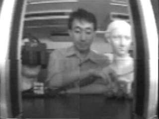
11 Figure 6. System configuration for the real-time video-based rendering system. Here, using observer viewpoint (X a,y a,z a ) and approximate distance Z i to the subject, the computer processes the 16-section video input and synthesizes desired pictures. In this paper, we handle video input as texture and achieve high-speed processing using a graphic engine Experimental results An external view of the camera system that we constructed is shown in Fig. 7. It consists of 16 CCD cameras (MTV-2510EM) arranged on a board in a 4-by-4 array with a camera spacing of 4 [cm]. This system can sample, at intervals of 4 [cm], light rays passing through a 12 [cm] square plane. Examples of moving pictures synthesized in real time are shown in Fig. 8. On the left are 16-section input images, and on the right are synthesized images achieved by a texture-mapping function targeting the areas enclosed by the white squares in the corresponding 16-section input image. These synthesized images are the result of virtually moving the viewpoint back and forth while looking between the walls from the fixed camera system. Specifically, in order from top to bottom in the figure, the camera moves backward (in a direction away from the character figures) in a virtual manner. As shown, the images of these figures become progressively

12 Figure 7. Camera array system. smaller. Note that occlusion occurring between the wall in the foreground and an inner figure has been reproduced. This is a 3D visual effect that cannot be obtained simply by zooming in or out. Object position Z i can also be made to coincide with the position of the figures by mouse operation. Here, while errors occur in the foreground wall and background, favorable synthesis is achieved with regard to the area surrounding the figures. For picture synthesis, we used Onyx2 Reality (R MHz 2) equipment manufactured by SGI and a video texture function through DIVO (DIgital Video Option). Processing for extracting and aligning texture according to viewpoint was performed at 47 [frames/sec]. This figure is greater than the 30 [frames/sec] of video input, which indicates the possibility of even more complex processing. 4. ACQUISITION OF DENSE DATA SPACE UTILIZING INTEGRAL PHOTOGRAPHY In section 3, we reported on the real-time application of the planar recording method using a camera array. In this section, we describe a technique that samples ray data at a much greater density than a camera array by using integral photography (IP) as the input format Using a real-time IP system The NHK Science and Technical Research Laboratories has achieved a real-time fullcolor IP system using a bundle of optical fibers and a high-definition camera. 24,25 In this system, the high-definition camera picks up the inverted image of a target object as elemental images, the number of which corresponds exactly to the number of lenses (optical fibers). An example is shown in Fig. 9.


13 Figure 8. Results of real-time video-based rendering.

14 Figure 9. Example of IP image. In this section, we examine a system that feeds an image like the one shown here to a computer and synthesizes a new image interactively according to the position of the observer without the use of special optics. The method of section 3 and the method described here are compared in Table 1. In either case, we have a method that deals with function f (X, Y, x, y) of the planar recording method. There is a difference, however, in how they sample ray data. Table 1. Comparisons of methods in sections 3 and 4 Method No. of Views No. of Pixels in Elemental Image (X, Y resolution) (x, y resolution) Section About Section About In short, these two input systems differ only in the way they sample ray data, and the algorithm of the ray representation method can be equally applied to both. The experimental results presented below were obtained by applying the algorithm described in section 3 to the IP image (Fig. 9) captured by a high-definition camera.
 corresponds to the resolution of the synthesized image. Figure 11, on the Figure 10. Result of simulating IP playback optics. Figure 11. Result of the proposed method.")
15 4.2. Experimental results Figure 10 shows the results of simulating IP playback optics by computer with respect to the input image of Fig. 9. The number of elemental images in this setup (54 57) corresponds to the resolution of the synthesized image. Figure 11, on the Figure 10. Result of simulating IP playback optics. Figure 11. Result of the proposed method. other hand, shows the results of applying the method of section 3 to IP input. In the left picture, depth parameter Z i has been adjusted for the dog in the front, while in the right picture, it has been adjusted for the dog in the back. Picture quality partially improves according to object depth. Figure 12 shows results for different types of source pictures. These results demonstrate that the method of section 3 is effective for objects that reflect in a shiny and complex manner and for moving objects like people. The above images were synthesized in real time while interactively varying viewpoint and depth parameter Z i of the object.

 has found wide use in the field of picture")


16 Figure 12. Other results for objects that reflect in a shiny and complex manner and for moving objects like people. 5. COMPRESSION OF RAY DATA An important issue in the ray representation method is how to efficiently compress the huge volume of spatial data present D discrete cosine transform Compression using the discrete cosine transform (DCT) has found wide use in the field of picture encoding. Here, in contrast to two dimensions in the case of pictures, we can consider four-dimensional DCT targeting the function f (P, Q, θ, φ). In particular, by defining 4D zigzag scanning and the like for DCT coefficients, this approach has been found to be an effective method of compressing ray data Improving compression efficiency by redefining the boundary surface Let s take another look at the 4D data space f (X, Y, x, y) described in section 3. We know that data on light rays passing through plane Z = 0 will be recorded in f (X, Y, x, y). If we now consider light rays that pass though plane Z = Z a,we
17 can derive an expression for 4D data space g(x, Y, x, y) in the same manner as Eq. (19), as shown below. g(x, Y, x, y) =f (X + Z a x, Y + Z a y, x, y) (20) In other words, the boundary surface may be redefined while preserving ray data. Furthermore, by making use of the fact that redundancy in ray data becomes easier to use by selecting an appropriate value for Z a, it becomes possible to further improve compression by 4D DCT. In general, a greater improvement in compression efficiency by 4D DCT is observed when setting Z a near the object and recording ray data in g(x, Y, x, y) as compared to defining a boundary surface far from the object and configuring 4D data space f (X, Y, x, y) Virtual object surface Expanding on the above ideas, we can do more than just bring the boundary surface closer to the object. We can also define a surface or layer approximating the shape of the object and thereby make it possible to perform even more efficient data compression. This is equivalent to enclosing the object in a 3D display (a surface for which the manner of viewing changes according to viewpoint). In the following, this kind of surface that approximates the shape of the object to handle ray data is called a virtual object surface. When recording and transmitting visual information of an object using a virtual object surface, there are two types of data that must be conveyed: Data on the shape of the virtual object surface Data on the light rays that pass through the virtual object surface From the standpoint of data compression, we can consider that a virtual-object-surface shape that closely approximates the shape of the object results in high correlation among the rays at a single point on the virtual object surface and simplifies the compression of ray data. On the other hand, we can expect that the amount of data needed to describe the shape of a virtual object surface to increase as that shape becomes more complex. In other words, we have a tradeoff relationship, and there exists an optimal degree of shape approximation that minimizes the total amount of data Experimental results We compare compression efficiency for ray data under a variety of conditions as described below (Fig. 13).
18 Figure 13. Relationship between various experiments.
 Z a is optimally set and compression with respect to g(x, Y, x, y) is performed by 4D DCT (e) Each layer in the layered model shown in Fig.")
19 (a) Each image of a multi-view picture is compressed by JPEG (b) A multi-view picture is treated as a moving picture and compressed by MPEG2 (c) Compression with respect to f (X, Y, x, y) is performed by 4D DCT (d) Z a is optimally set and compression with respect to g(x, Y, x, y) is performed by 4D DCT (e) Each layer in the layered model shown in Fig. 14 is compressed by 4D DCT as a virtual object surface (f) Texture data in the layered model is treated separately in the technique described in (e) Figure 14. Example of layered model. Conditions (a) and (b) constitute an experiment with the aim of comparing conventional techniques with the proposed method. Conditions (c), (d), and (e), on the other hand, constitute an experiment to compare various techniques that use the 4D DCT method described earlier. Condition (f), meanwhile, has been added to these experiments as a technique for separately transmitting texture in the layered model beforehand considering the difficulty of interactive image display if 4D DCT is time consuming. Experimental results are shown in Fig. 15. The horizontal axis shows total code length required to transmit the multi-view picture, and the vertical axis shows average SNR at various capture points. The amount of data in the multi-view picture before encoding is 437 [Mb]. Using a virtual object surface in technique (d) produces better results than conventional techniques (a) and (b), and using a layered model in (e) improves the compression ratio to 345:1 at 36.3 [db]. Technique (f), on the other hand, incurs
20 Figure 15. Experimental results. overhead in texture encoding and a subsequent drop in compression rate compared to (e), but is nevertheless capable of interactive video display. We have therefore confirmed that using redundancy in 4D data space makes for efficient compression surpassing that performed on individual 2D pictures. 6. SAMPLING RAY DATA BY A TELECENTRIC LENS As described in section 2, 4D data space f (P, Q, θ, φ) can be treated as a set of orthogonal projection images f a(p, Q). Accordingly, the use of a telecentric lens that can directly capture orthogonal projection images makes it possible to obtain a 4D data space directly. 19 While sections 3, 4, and 5 have focused on techniques based on the planar recording method, this section describes an experiment using the spherical recording method that can handle orthogonal projection images without distortion Capturing orthogonal projection images In the experiment, orthogonal projection images of a set of objects are first captured from multiple directions. Some of these images are shown in Fig. 16. Specifically, these are images of two cubes of the same size arranged one behind the other. It can be seen that both objects in a pair are displayed with the same size regardless of the distance from the lens. This confirms that the telecentric lens is taking orthogonal projection images. These images can now be used to configure 4D data space by spherical recording Synthesis of perspective views Figure 17 shows the results of synthesizing perspective views of the objects described above at various viewpoints by reading out appropriate ray data from 4D data space.


21 Figure 16. Examples of orthogonal projection images. We can see here how two objects in a pair are now displayed with different sizes in accordance with their relative positions. Figure 17. Results of synthesizing perspective projection images from a set of orthogonal projection images. Capturing a large volume of orthogonal projection images enables perspective views to be synthesized at a variety of viewpoints. 7. CONCLUSION This paper has presented a technique of representing 3D spatial information based on ray data. Three methods of recording ray data were formalized here: planar
22 recording, cylindrical recording, and spherical recording. In comparison with past techniques that use perspective projection images, this technique uses orthogonal projection images that enable spatial representation independent of viewpoint. The effectiveness of the proposed technique has been demonstrated experimentally by synthesizing 3D computer graphics using, for example, a real-time video-based rendering system and integral photography. This paper has also proposed the concept of a virtual object surface and has demonstrated its effectiveness in compressing ray data. Finally, the use of a telecentric lens was examined as a way of directly obtaining ray data, and its effectiveness was also demonstrated by experiment. This ray representation method is a simple and straightforward approach to the problem of how to represent 3D space, an issue shared by various fields including 3D image communications, computer graphics, and virtual reality. In future research, we plan to continue our efforts in systematizing basic theory and to further develop various elemental technologies associated with input systems (camera array, integral photography, and telecentric lenses), compression and transmission methods (virtual object surface, 4D DCT), and interactive display systems (image-based rendering). ACKNOWLEDGEMENTS The authors would like to extend their appreciation to NHK Science and Technical Research Laboratories for Fig. 9, an IP image taken by them, and to Tsukuba University for use of their multi-view image database to synthesize Fig. 14. REFERENCES 1. H. Harashima, Three-dimensional image coding, future prospect, Picture Coding Symposium of Japan (PCSJ 92), pp. 9 12, 1992 (in Japanese). 2. T. Motoki, H. Isono and I. Yuyama, Present status of three-dimensional television research, Proc. IEEE, 83, 7, pp , T. Naemura, M. Kaneko, and H. Harashima, Compression and Representation of 3-D Images, IEICE Trans. Inf. & Syst.(Invited Survey Paper), E82-D, 3, pp , T. Fujii and H. Harashima, Data compression and interpolation of multi-view image set, Inst. Electron. Inform. Commun. Eng. (IEICE) Trans. Inf. & Syst., E77-D, 9, pp , D. V. Papadimitriou and T. J. Dennis, Stereo in model-based image coding, Picture Coding Symposium (PCS 94), pp (1994). 6. J. R. Ohm and M. E. Izquierdo, An object-based system for stereoscopic viewpoint synthesis, IEEE Trans. Circuits & Syst. Video Technol., 7, 5, pp , T. Naemura, M. Kaneko, and H. Harashima, 3-D object based coding of multiview images, Picture Coding Symposium (PCS 96), pp , D. Tzovaras, N. Grammalidis and M. G. Strintzis, Object-based coding of stereo image sequences using joint 3-D motion/disparity compression,, IEEE Trans. Circuits & Syst. Video Technol., 7, 2, pp , T. Fujii, A basic study on the integrated 3-D visual communication, Ph.D thesis, Course of Elec. Eng., The Univ. of Tokyo, 1994 (in Japanese).
23 10. T. Yanagisawa, T. Naemura, M. Kaneko, and H. Harashima, Handling of 3- dimensional objects in ray space, the Inform. and Syst. Society Conf. of Inst. Electron. Inform. Commun. Eng. (IEICE), D-169, 1995 (in Japanese). 11. A. Katayama, K. Tanaka, T. Oshino, and H.Tamura, A viewpoint independent stereoscopic display using interpolating of multi-viewpoint images, SPIE Stereoscopic displays and virtualreality systems II, 2409, pp , L. McMillan and G. Bishop, Plenoptic modeling : An image-based rendering system, SIGGRAPH 95, pp , M. Levoy and P. Hanrahan, Light Field Rendering, SIGGRAPH 96, pp , S. Gortler, R. Grzeszczuk, R. Szeliski and, M. Cohen, The Lumigraph, SIG- GRAPH 96, pp , T. Naemura, M. Kaneko, and H. Harashima, Orthographic approach to representing 3-D images and interpolating light rays for 3-D image communication and virtual environment, Signal Process. : Image Commun., 14, pp , T. Naemura and H. Harashima, Real-Time Video-Based Rendering for Augmented Spatial Communication, SPIE Visual Commun. and Image Process. (VCIP 99), 3653, pp , T. Yoshida, T. Naemura and H. Harashima, 3-D Computer Graphics Based on Integral Photography, 3D Image Conf., pp , 2000 (in Japanese). 18. T. Takano, T. Naemura, H. Harashima, 3-D space coding using Virtual Object Surface, Inst. Electron. Inform. Commun. Eng. (IEICE) Trans., J82-D-II, pp , 1999 (in Japanese). 19. K.Takeuchi, T.Naemura and H.Harashima, Acquisition of light rays using telecentric lens, J. Inst. of Image Inform. and Television Eng., 54, 10, 2000 (to appear in Japanese). 20. E. Adelson and J. Bergen, The plenoptic function and the elements of early vision, Computer Models of Visual Processing, M. Landy and J. Movshon, ed., Chapter 1, MIT Press, S. E. Chen, QuickTimeVR - an image-based approach to virtual environment navigation -, SIGGRAPH 95, pp , T. Fujii, T. Kimoto, and M. Tanimoto, Data compression of 3-D spatial information based on ray-space coding, J. Inst. of Image Inform. and Television Eng., 52, 3, pp , 1998 (in Japanese). 23. R. C. Bolles, H. H. Baker, and D. H. Marimont, Epipolar-plane image analysis : an approach to determining structure from motion, Int l J. Computer Vision, 1, pp. 7 55, F. Okano, H. Hoshino, J. Arai and I. Yuyama, Real-time Pickup Method for a Three-dimensional Image based on Integral Photography, Applied Optics, 36, 7, pp , H. Hoshino, F. Okano, H. Isono and I. Yuyama, Analysis of resolution limitation of integral photography, Optical Society of America A, 15, 8, pp , 1998.
24 26. T. Takano, T. Naemura, M. Kaneko, and H. Harashima, 3-D space coding based on light ray data - Local expansion of compressed light ray data -, J. Inst. of Image Inform. and Television Eng., 52, 9, pp , 1998 (in Japanese).
Real-time Generation and Presentation of View-dependent Binocular Stereo Images Using a Sequence of Omnidirectional Images
 Real-time Generation and Presentation of View-dependent Binocular Stereo Images Using a Sequence of Omnidirectional Images Abstract This paper presents a new method to generate and present arbitrarily
Real-Time Video- Based Modeling and Rendering of 3D Scenes
 Image-Based Modeling, Rendering, and Lighting Real-Time Video- Based Modeling and Rendering of 3D Scenes Takeshi Naemura Stanford University Junji Tago and Hiroshi Harashima University of Tokyo In research
View Generation for Free Viewpoint Video System
 View Generation for Free Viewpoint Video System Gangyi JIANG 1, Liangzhong FAN 2, Mei YU 1, Feng Shao 1 1 Faculty of Information Science and Engineering, Ningbo University, Ningbo, 315211, China 2 Ningbo
A Review of Image- based Rendering Techniques Nisha 1, Vijaya Goel 2 1 Department of computer science, University of Delhi, Delhi, India
 A Review of Image- based Rendering Techniques Nisha 1, Vijaya Goel 2 1 Department of computer science, University of Delhi, Delhi, India Keshav Mahavidyalaya, University of Delhi, Delhi, India Abstract
Real-time Rendering System of Moving Objects
 Real-time Rendering System o Moving Objects Yutaka Kunita Masahiko Inami Taro Maeda Susumu Tachi Department o Mathematical Engineering and Inormation Physics Graduate Shool o Engineering, The University
Natural Viewing 3D Display
 We will introduce a new category of Collaboration Projects, which will highlight DoCoMo s joint research activities with universities and other companies. DoCoMo carries out R&D to build up mobile communication,
Mosaics, Plenoptic Function, and Light Field Rendering. Last Lecture
 Mosaics, Plenoptic Function, and Light Field Rendering Topics in Image-ased Modeling and Rendering CSE291 J00 Lecture 3 Last Lecture Camera Models Pinhole perspective Affine/Orthographic models Homogeneous
Three-Dimensional Measurement of Objects in Liquid with an Unknown Refractive Index Using Fisheye Stereo Camera
 Three-Dimensional Measurement of Objects in Liquid with an Unknown Refractive Index Using Fisheye Stereo Camera Kazuki Sakamoto, Alessandro Moro, Hiromitsu Fujii, Atsushi Yamashita, and Hajime Asama Abstract
There are many cues in monocular vision which suggests that vision in stereo starts very early from two similar 2D images. Lets see a few...
 STEREO VISION The slides are from several sources through James Hays (Brown); Srinivasa Narasimhan (CMU); Silvio Savarese (U. of Michigan); Bill Freeman and Antonio Torralba (MIT), including their own
Measurement of Pedestrian Groups Using Subtraction Stereo
 Measurement of Pedestrian Groups Using Subtraction Stereo Kenji Terabayashi, Yuki Hashimoto, and Kazunori Umeda Chuo University / CREST, JST, 1-13-27 Kasuga, Bunkyo-ku, Tokyo 112-8551, Japan terabayashi@mech.chuo-u.ac.jp
Dense 3-D Reconstruction of an Outdoor Scene by Hundreds-baseline Stereo Using a Hand-held Video Camera
 Dense 3-D Reconstruction of an Outdoor Scene by Hundreds-baseline Stereo Using a Hand-held Video Camera Tomokazu Satoy, Masayuki Kanbaray, Naokazu Yokoyay and Haruo Takemuraz ygraduate School of Information
Acquisition and Visualization of Colored 3D Objects
 Acquisition and Visualization of Colored 3D Objects Kari Pulli Stanford University Stanford, CA, U.S.A kapu@cs.stanford.edu Habib Abi-Rached, Tom Duchamp, Linda G. Shapiro and Werner Stuetzle University
COSC579: Scene Geometry. Jeremy Bolton, PhD Assistant Teaching Professor
 COSC579: Scene Geometry Jeremy Bolton, PhD Assistant Teaching Professor Overview Linear Algebra Review Homogeneous vs non-homogeneous representations Projections and Transformations Scene Geometry The
View Synthesis for Multiview Video Compression
 View Synthesis for Multiview Video Compression Emin Martinian, Alexander Behrens, Jun Xin, and Anthony Vetro email:{martinian,jxin,avetro}@merl.com, behrens@tnt.uni-hannover.de Mitsubishi Electric Research
Sample Based Texture extraction for Model based coding
 DEPARTMENT OF APPLIED PHYSICS AND ELECTRONICS UMEÅ UNIVERISTY, SWEDEN DIGITAL MEDIA LAB Sample Based Texture extraction for Model based coding Zhengrong Yao 1 Dept. Applied Physics and Electronics Umeå
IMAGE-BASED RENDERING TECHNIQUES FOR APPLICATION IN VIRTUAL ENVIRONMENTS
 IMAGE-BASED RENDERING TECHNIQUES FOR APPLICATION IN VIRTUAL ENVIRONMENTS Xiaoyong Sun A Thesis submitted to the Faculty of Graduate and Postdoctoral Studies in partial fulfillment of the requirements for
Introduction to Computer Vision. Introduction CMPSCI 591A/691A CMPSCI 570/670. Image Formation
 Introduction CMPSCI 591A/691A CMPSCI 570/670 Image Formation Lecture Outline Light and Optics Pinhole camera model Perspective projection Thin lens model Fundamental equation Distortion: spherical & chromatic
Extended Fractional View Integral Photography Using Slanted Orthogonal Lenticular Lenses
 Proceedings of the 2 nd World Congress on Electrical Engineering and Computer Systems and Science (EECSS'16) Budapest, Hungary August 16 17, 2016 Paper No. MHCI 112 DOI: 10.11159/mhci16.112 Extended Fractional
Shape as a Perturbation to Projective Mapping
 Leonard McMillan and Gary Bishop Department of Computer Science University of North Carolina, Sitterson Hall, Chapel Hill, NC 27599 email: mcmillan@cs.unc.edu gb@cs.unc.edu 1.0 Introduction In the classical
Range Imaging Through Triangulation. Range Imaging Through Triangulation. Range Imaging Through Triangulation. Range Imaging Through Triangulation
 Obviously, this is a very slow process and not suitable for dynamic scenes. To speed things up, we can use a laser that projects a vertical line of light onto the scene. This laser rotates around its vertical
View Synthesis for Multiview Video Compression
 MITSUBISHI ELECTRIC RESEARCH LABORATORIES http://www.merl.com View Synthesis for Multiview Video Compression Emin Martinian, Alexander Behrens, Jun Xin, and Anthony Vetro TR2006-035 April 2006 Abstract
(x,0) 0. X U f(x,y,z,θ, φ) V(a,b,c) f(x,u ) 0 0
 0. X U f(x,y,z,θ, φ) V(a,b,c) f(x,u ) 0 0") A Hardware Ray-Space Data Renderer for Interactive Augmented Virtuality Yukio Sakagawa, Akihiro Katayama, Daisuke Kotake, and Hideyuki Tamura Mixed Reality Systems Laboratory Inc. E-mail: fsakagawa, katayama,
A Hardware Ray-Space Data Renderer for Interactive Augmented Virtuality Yukio Sakagawa, Akihiro Katayama, Daisuke Kotake, and Hideyuki Tamura Mixed Reality Systems Laboratory Inc. E-mail: fsakagawa, katayama,
Vision-Based 3D Fingertip Interface for Spatial Interaction in 3D Integral Imaging System
 International Conference on Complex, Intelligent and Software Intensive Systems Vision-Based 3D Fingertip Interface for Spatial Interaction in 3D Integral Imaging System Nam-Woo Kim, Dong-Hak Shin, Dong-Jin
A Fast Image Multiplexing Method Robust to Viewer s Position and Lens Misalignment in Lenticular 3D Displays
 A Fast Image Multiplexing Method Robust to Viewer s Position and Lens Misalignment in Lenticular D Displays Yun-Gu Lee and Jong Beom Ra Department of Electrical Engineering and Computer Science Korea Advanced
Image Formation. Antonino Furnari. Image Processing Lab Dipartimento di Matematica e Informatica Università degli Studi di Catania
 Image Formation Antonino Furnari Image Processing Lab Dipartimento di Matematica e Informatica Università degli Studi di Catania furnari@dmi.unict.it 18/03/2014 Outline Introduction; Geometric Primitives
Motion. 1 Introduction. 2 Optical Flow. Sohaib A Khan. 2.1 Brightness Constancy Equation
 Motion Sohaib A Khan 1 Introduction So far, we have dealing with single images of a static scene taken by a fixed camera. Here we will deal with sequence of images taken at different time intervals. Motion
Hybrid Rendering for Collaborative, Immersive Virtual Environments
 Hybrid Rendering for Collaborative, Immersive Virtual Environments Stephan Würmlin wuermlin@inf.ethz.ch Outline! Rendering techniques GBR, IBR and HR! From images to models! Novel view generation! Putting
View Synthesis Prediction for Rate-Overhead Reduction in FTV
 MITSUBISHI ELECTRIC RESEARCH LABORATORIES http://www.merl.com View Synthesis Prediction for Rate-Overhead Reduction in FTV Sehoon Yea, Anthony Vetro TR2008-016 June 2008 Abstract This paper proposes the
Absolute Scale Structure from Motion Using a Refractive Plate
 Absolute Scale Structure from Motion Using a Refractive Plate Akira Shibata, Hiromitsu Fujii, Atsushi Yamashita and Hajime Asama Abstract Three-dimensional (3D) measurement methods are becoming more and
But, vision technology falls short. and so does graphics. Image Based Rendering. Ray. Constant radiance. time is fixed. 3D position 2D direction
 Computer Graphics -based rendering Output Michael F. Cohen Microsoft Research Synthetic Camera Model Computer Vision Combined Output Output Model Real Scene Synthetic Camera Model Real Cameras Real Scene
Transactions on Information and Communications Technologies vol 19, 1997 WIT Press, ISSN
 Hopeld Network for Stereo Correspondence Using Block-Matching Techniques Dimitrios Tzovaras and Michael G. Strintzis Information Processing Laboratory, Electrical and Computer Engineering Department, Aristotle
Avatar Communication: Virtual Instructor in the Demonstration Exhibit
 Avatar Communication: Virtual Instructor in the Demonstration Exhibit Tetsuro Ogi 1, 2, 3, Toshio Yamada 1, Takuro Kayahara 1, 2, Yuji Kurita 1 1 Telecommunications Advancement Organization of Japan 2
Outdoor Scene Reconstruction from Multiple Image Sequences Captured by a Hand-held Video Camera
 Outdoor Scene Reconstruction from Multiple Image Sequences Captured by a Hand-held Video Camera Tomokazu Sato, Masayuki Kanbara and Naokazu Yokoya Graduate School of Information Science, Nara Institute
A Sketch Interpreter System with Shading and Cross Section Lines
 Journal for Geometry and Graphics Volume 9 (2005), No. 2, 177 189. A Sketch Interpreter System with Shading and Cross Section Lines Kunio Kondo 1, Haruki Shizuka 1, Weizhong Liu 1, Koichi Matsuda 2 1 Dept.
Understanding Variability
 Understanding Variability Why so different? Light and Optics Pinhole camera model Perspective projection Thin lens model Fundamental equation Distortion: spherical & chromatic aberration, radial distortion
International Journal of Advanced Research in Computer Science and Software Engineering
 Volume 2, Issue 8, August 2012 ISSN: 2277 128X International Journal of Advanced Research in Computer Science and Software Engineering Research Paper Available online at: www.ijarcsse.com A Study on Block
Visual Recognition: Image Formation
 Visual Recognition: Image Formation Raquel Urtasun TTI Chicago Jan 5, 2012 Raquel Urtasun (TTI-C) Visual Recognition Jan 5, 2012 1 / 61 Today s lecture... Fundamentals of image formation You should know
Image Base Rendering: An Introduction
 Image Base Rendering: An Introduction Cliff Lindsay CS563 Spring 03, WPI 1. Introduction Up to this point, we have focused on showing 3D objects in the form of polygons. This is not the only approach to
Aberrations in Holography
 Aberrations in Holography D Padiyar, J Padiyar 1070 Commerce St suite A, San Marcos, CA 92078 dinesh@triple-take.com joy@triple-take.com Abstract. The Seidel aberrations are described as they apply to
Computational Photography
 Computational Photography Photography and Imaging Michael S. Brown Brown - 1 Part 1 Overview Photography Preliminaries Traditional Film Imaging (Camera) Part 2 General Imaging 5D Plenoptic Function (McMillan)
DD2423 Image Analysis and Computer Vision IMAGE FORMATION. Computational Vision and Active Perception School of Computer Science and Communication
 DD2423 Image Analysis and Computer Vision IMAGE FORMATION Mårten Björkman Computational Vision and Active Perception School of Computer Science and Communication November 8, 2013 1 Image formation Goal:
Motion Analysis. Motion analysis. Now we will talk about. Differential Motion Analysis. Motion analysis. Difference Pictures
 Now we will talk about Motion Analysis Motion analysis Motion analysis is dealing with three main groups of motionrelated problems: Motion detection Moving object detection and location. Derivation of
Live Video Integration for High Presence Virtual World
 Live Video Integration for High Presence Virtual World Tetsuro OGI, Toshio YAMADA Gifu MVL Research Center, TAO IML, The University of Tokyo 2-11-16, Yayoi, Bunkyo-ku, Tokyo 113-8656, Japan Michitaka HIROSE
A New Data Format for Multiview Video
 A New Data Format for Multiview Video MEHRDAD PANAHPOUR TEHRANI 1 AKIO ISHIKAWA 1 MASASHIRO KAWAKITA 1 NAOMI INOUE 1 TOSHIAKI FUJII 2 This paper proposes a new data forma that can be used for multiview
Introduction to 3D Concepts
 PART I Introduction to 3D Concepts Chapter 1 Scene... 3 Chapter 2 Rendering: OpenGL (OGL) and Adobe Ray Tracer (ART)...19 1 CHAPTER 1 Scene s0010 1.1. The 3D Scene p0010 A typical 3D scene has several
Distortion Correction for Conical Multiplex Holography Using Direct Object-Image Relationship
 Proc. Natl. Sci. Counc. ROC(A) Vol. 25, No. 5, 2001. pp. 300-308 Distortion Correction for Conical Multiplex Holography Using Direct Object-Image Relationship YIH-SHYANG CHENG, RAY-CHENG CHANG, AND SHIH-YU
PAPER Three-Dimensional Scene Walkthrough System Using Multiple Acentric Panorama View (APV) Technique
 Technique") IEICE TRANS. INF. & SYST., VOL.E86 D, NO.1 JANUARY 2003 117 PAPER Three-Dimensional Scene Walkthrough System Using Multiple Acentric Panorama View (APV) Technique Ping-Hsien LIN and Tong-Yee LEE, Nonmembers
IEICE TRANS. INF. & SYST., VOL.E86 D, NO.1 JANUARY 2003 117 PAPER Three-Dimensional Scene Walkthrough System Using Multiple Acentric Panorama View (APV) Technique Ping-Hsien LIN and Tong-Yee LEE, Nonmembers
Multiple View Geometry
 Multiple View Geometry Martin Quinn with a lot of slides stolen from Steve Seitz and Jianbo Shi 15-463: Computational Photography Alexei Efros, CMU, Fall 2007 Our Goal The Plenoptic Function P(θ,φ,λ,t,V
Today. Stereo (two view) reconstruction. Multiview geometry. Today. Multiview geometry. Computational Photography
 reconstruction. Multiview geometry. Today. Multiview geometry. Computational Photography") Computational Photography Matthias Zwicker University of Bern Fall 2009 Today From 2D to 3D using multiple views Introduction Geometry of two views Stereo matching Other applications Multiview geometry
Computational Photography Matthias Zwicker University of Bern Fall 2009 Today From 2D to 3D using multiple views Introduction Geometry of two views Stereo matching Other applications Multiview geometry
DEVELOPMENT OF REAL TIME 3-D MEASUREMENT SYSTEM USING INTENSITY RATIO METHOD
 DEVELOPMENT OF REAL TIME 3-D MEASUREMENT SYSTEM USING INTENSITY RATIO METHOD Takeo MIYASAKA and Kazuo ARAKI Graduate School of Computer and Cognitive Sciences, Chukyo University, Japan miyasaka@grad.sccs.chukto-u.ac.jp,
Ray tracing based fast refraction method for an object seen through a cylindrical glass
 20th International Congress on Modelling and Simulation, Adelaide, Australia, 1 6 December 2013 www.mssanz.org.au/modsim2013 Ray tracing based fast refraction method for an object seen through a cylindrical
Lecture 17: Recursive Ray Tracing. Where is the way where light dwelleth? Job 38:19
 Lecture 17: Recursive Ray Tracing Where is the way where light dwelleth? Job 38:19 1. Raster Graphics Typical graphics terminals today are raster displays. A raster display renders a picture scan line
Digital Image Correlation of Stereoscopic Images for Radial Metrology
 Digital Image Correlation of Stereoscopic Images for Radial Metrology John A. Gilbert Professor of Mechanical Engineering University of Alabama in Huntsville Huntsville, AL 35899 Donald R. Matthys Professor
5LSH0 Advanced Topics Video & Analysis
 1 Multiview 3D video / Outline 2 Advanced Topics Multimedia Video (5LSH0), Module 02 3D Geometry, 3D Multiview Video Coding & Rendering Peter H.N. de With, Sveta Zinger & Y. Morvan ( p.h.n.de.with@tue.nl
1-2 Feature-Based Image Mosaicing
 MVA'98 IAPR Workshop on Machine Vision Applications, Nov. 17-19, 1998, Makuhari, Chibq Japan 1-2 Feature-Based Image Mosaicing Naoki Chiba, Hiroshi Kano, Minoru Higashihara, Masashi Yasuda, and Masato
CS223b Midterm Exam, Computer Vision. Monday February 25th, Winter 2008, Prof. Jana Kosecka
 CS223b Midterm Exam, Computer Vision Monday February 25th, Winter 2008, Prof. Jana Kosecka Your name email This exam is 8 pages long including cover page. Make sure your exam is not missing any pages.
Chapters 1 7: Overview
 Chapters 1 7: Overview Chapter 1: Introduction Chapters 2 4: Data acquisition Chapters 5 7: Data manipulation Chapter 5: Vertical imagery Chapter 6: Image coordinate measurements and refinements Chapter
Cybercity Walker - Layered Morphing Method -
 Cybercity Walker - Layered Morphing Method - Takaaki Endo 1), Akihiro Katayama 1), Hideyuki Tamura 1), Michitaka Hirose 2), and Tomohiro Tanikawa 2) 1) Mixed Reality Systems Laboratory Inc. 6-145 Hanasakicho,
Computer Vision. Coordinates. Prof. Flávio Cardeal DECOM / CEFET- MG.
 Computer Vision Coordinates Prof. Flávio Cardeal DECOM / CEFET- MG cardeal@decom.cefetmg.br Abstract This lecture discusses world coordinates and homogeneous coordinates, as well as provides an overview
Image-Based Rendering
 Image-Based Rendering COS 526, Fall 2016 Thomas Funkhouser Acknowledgments: Dan Aliaga, Marc Levoy, Szymon Rusinkiewicz What is Image-Based Rendering? Definition 1: the use of photographic imagery to overcome
A Simple Vision System
 Chapter 1 A Simple Vision System 1.1 Introduction In 1966, Seymour Papert wrote a proposal for building a vision system as a summer project [4]. The abstract of the proposal starts stating a simple goal:
3-D Shape Reconstruction from Light Fields Using Voxel Back-Projection
 3-D Shape Reconstruction from Light Fields Using Voxel Back-Projection Peter Eisert, Eckehard Steinbach, and Bernd Girod Telecommunications Laboratory, University of Erlangen-Nuremberg Cauerstrasse 7,
Camera Calibration for Video See-Through Head-Mounted Display. Abstract. 1.0 Introduction. Mike Bajura July 7, 1993
 Camera Calibration for Video See-Through Head-Mounted Display Mike Bajura July 7, 1993 Abstract This report describes a method for computing the parameters needed to model a television camera for video
COMP 558 lecture 16 Nov. 8, 2010
 Shading The term shading typically refers to variations in irradiance along a smooth Lambertian surface. Recall that if a surface point is illuminated by parallel light source from direction l, then the
Reflection and Refraction of Light
 PC1222 Fundamentals of Physics II Reflection and Refraction of Light 1 Objectives Investigate for reflection of rays from a plane surface, the dependence of the angle of reflection on the angle of incidence.
Chapter 8 Three-Dimensional Viewing Operations
 Projections Chapter 8 Three-Dimensional Viewing Operations Figure 8.1 Classification of planar geometric projections Figure 8.2 Planar projection Figure 8.3 Parallel-oblique projection Figure 8.4 Orthographic
Plenoptic Image Editing
 Plenoptic Image Editing Steven M. Seitz Computer Sciences Department University of Wisconsin Madison Madison, WI53706 seitz@cs.wisc.edu Kiriakos N. Kutulakos Department of Computer Science University of
3D Environment Measurement Using Binocular Stereo and Motion Stereo by Mobile Robot with Omnidirectional Stereo Camera
 3D Environment Measurement Using Binocular Stereo and Motion Stereo by Mobile Robot with Omnidirectional Stereo Camera Shinichi GOTO Department of Mechanical Engineering Shizuoka University 3-5-1 Johoku,
Image Based Rendering
 Image Based Rendering an overview Photographs We have tools that acquire and tools that display photographs at a convincing quality level 2 1 3 4 2 5 6 3 7 8 4 9 10 5 Photographs We have tools that acquire
DECODING COMPLEXITY CONSTRAINED RATE-DISTORTION OPTIMIZATION FOR THE COMPRESSION OF CONCENTRIC MOSAICS
 DECODING COMPLEXITY CONSTRAINED RATE-DISTORTION OPTIMIZATION FOR THE COMPRESSION OF CONCENTRIC MOSAICS Eswar Kalyan Vutukuri, Ingo Bauerman and Eckehard Steinbach Institute of Communication Networks, Media
The Reflection of Light
 King Saud University College of Applied Studies and Community Service Department of Natural Sciences The Reflection of Light General Physics II PHYS 111 Nouf Alkathran nalkathran@ksu.edu.sa Outline Introduction
Realtime View Adaptation of Video Objects in 3-Dimensional Virtual Environments
 Contact Details of Presenting Author Edward Cooke (cooke@hhi.de) Tel: +49-30-31002 613 Fax: +49-30-3927200 Summation Abstract o Examination of the representation of time-critical, arbitrary-shaped, video
CHAPTER 9 INPAINTING USING SPARSE REPRESENTATION AND INVERSE DCT
 CHAPTER 9 INPAINTING USING SPARSE REPRESENTATION AND INVERSE DCT 9.1 Introduction In the previous chapters the inpainting was considered as an iterative algorithm. PDE based method uses iterations to converge
Video Compression Method for On-Board Systems of Construction Robots
 Video Compression Method for On-Board Systems of Construction Robots Andrei Petukhov, Michael Rachkov Moscow State Industrial University Department of Automatics, Informatics and Control Systems ul. Avtozavodskaya,
INTERACTIVE ENVIRONMENT FOR INTUITIVE UNDERSTANDING OF 4D DATA. M. Murata and S. Hashimoto Humanoid Robotics Institute, Waseda University, Japan
 1 INTRODUCTION INTERACTIVE ENVIRONMENT FOR INTUITIVE UNDERSTANDING OF 4D DATA M. Murata and S. Hashimoto Humanoid Robotics Institute, Waseda University, Japan Abstract: We present a new virtual reality
Morphable 3D-Mosaics: a Hybrid Framework for Photorealistic Walkthroughs of Large Natural Environments
 Morphable 3D-Mosaics: a Hybrid Framework for Photorealistic Walkthroughs of Large Natural Environments Nikos Komodakis and Georgios Tziritas Computer Science Department, University of Crete E-mails: {komod,
Computer Vision Lecture 17
 Computer Vision Lecture 17 Epipolar Geometry & Stereo Basics 13.01.2015 Bastian Leibe RWTH Aachen http://www.vision.rwth-aachen.de leibe@vision.rwth-aachen.de Announcements Seminar in the summer semester
Adaptive Zoom Distance Measuring System of Camera Based on the Ranging of Binocular Vision
 Adaptive Zoom Distance Measuring System of Camera Based on the Ranging of Binocular Vision Zhiyan Zhang 1, Wei Qian 1, Lei Pan 1 & Yanjun Li 1 1 University of Shanghai for Science and Technology, China
Accurate and Dense Wide-Baseline Stereo Matching Using SW-POC
 Accurate and Dense Wide-Baseline Stereo Matching Using SW-POC Shuji Sakai, Koichi Ito, Takafumi Aoki Graduate School of Information Sciences, Tohoku University, Sendai, 980 8579, Japan Email: sakai@aoki.ecei.tohoku.ac.jp
Shape from Textures Phenomenon for 3D Modeling Applications with Big Data Images
 Shape from Textures Phenomenon for 3D Modeling Applications with Big Data Images Kalaivani Thangamani, Takashi Okuma, Ryosuke Ichikari and Takeshi Kurata Service Sensing, Assimilation, and Modeling Research
Computer Vision Lecture 17
 Announcements Computer Vision Lecture 17 Epipolar Geometry & Stereo Basics Seminar in the summer semester Current Topics in Computer Vision and Machine Learning Block seminar, presentations in 1 st week
A High Speed Face Measurement System
 A High Speed Face Measurement System Kazuhide HASEGAWA, Kazuyuki HATTORI and Yukio SATO Department of Electrical and Computer Engineering, Nagoya Institute of Technology Gokiso, Showa, Nagoya, Japan, 466-8555
Occlusion Detection of Real Objects using Contour Based Stereo Matching
 Occlusion Detection of Real Objects using Contour Based Stereo Matching Kenichi Hayashi, Hirokazu Kato, Shogo Nishida Graduate School of Engineering Science, Osaka University,1-3 Machikaneyama-cho, Toyonaka,
Reflection and Refraction
 Reflection and Refraction Theory: Whenever a wave traveling in some medium encounters an interface or boundary with another medium either (or both) of the processes of (1) reflection and (2) refraction
Optics INTRODUCTION DISCUSSION OF PRINCIPLES. Reflection by a Plane Mirror
 Optics INTRODUCTION Geometric optics is one of the oldest branches of physics, dealing with the laws of reflection and refraction. Reflection takes place on the surface of an object, and refraction occurs
Image-based modeling (IBM) and image-based rendering (IBR)
 and image-based rendering (IBR)") Image-based modeling (IBM) and image-based rendering (IBR) CS 248 - Introduction to Computer Graphics Autumn quarter, 2005 Slides for December 8 lecture The graphics pipeline modeling animation rendering
Image-based modeling (IBM) and image-based rendering (IBR) CS 248 - Introduction to Computer Graphics Autumn quarter, 2005 Slides for December 8 lecture The graphics pipeline modeling animation rendering
Extensions of H.264/AVC for Multiview Video Compression
 MITSUBISHI ELECTRIC RESEARCH LABORATORIES http://www.merl.com Extensions of H.264/AVC for Multiview Video Compression Emin Martinian, Alexander Behrens, Jun Xin, Anthony Vetro, Huifang Sun TR2006-048 June
A Survey of Light Source Detection Methods
 A Survey of Light Source Detection Methods Nathan Funk University of Alberta Mini-Project for CMPUT 603 November 30, 2003 Abstract This paper provides an overview of the most prominent techniques for light
Virtual Human with regard to Physical contact and Eye contact
 Virtual Human with regard to Physical contact and Eye contact Asami Takayama 1, Yusuke Sugimoto 1, Akio Okuie1, Tomoya Suzuki 1 and Kiyotaka Kato 1 1 Tokyo Univ. of Science,1-3 Kagurazaka, Shinjuku-ku,Tokyo
Plenoptic Image Editing
 Plenoptic Image Editing Steven M. Seitz Computer Sciences Department University of Wisconsin Madison Madison, WI53706 Kiriakos N. Kutulakos Department of Computer Science University of Rochester Rochester,
Stereo Image Rectification for Simple Panoramic Image Generation
 Stereo Image Rectification for Simple Panoramic Image Generation Yun-Suk Kang and Yo-Sung Ho Gwangju Institute of Science and Technology (GIST) 261 Cheomdan-gwagiro, Buk-gu, Gwangju 500-712 Korea Email:{yunsuk,
Shading of a computer-generated hologram by zone plate modulation
 Shading of a computer-generated hologram by zone plate modulation Takayuki Kurihara * and Yasuhiro Takaki Institute of Engineering, Tokyo University of Agriculture and Technology, 2-24-16 Naka-cho, Koganei,Tokyo
Construction of an Immersive Mixed Environment Using an Omnidirectional Stereo Image Sensor
 Construction of an Immersive Mixed Environment Using an Omnidirectional Stereo Image Sensor Jun Shimamura, Naokazu Yokoya, Haruo Takemura and Kazumasa Yamazawa Graduate School of Information Science Nara
High-speed Three-dimensional Mapping by Direct Estimation of a Small Motion Using Range Images
 MECATRONICS - REM 2016 June 15-17, 2016 High-speed Three-dimensional Mapping by Direct Estimation of a Small Motion Using Range Images Shinta Nozaki and Masashi Kimura School of Science and Engineering
Three-dimensional integral imaging for orthoscopic real image reconstruction
 Three-dimensional integral imaging for orthoscopic real image reconstruction Jae-Young Jang, Se-Hee Park, Sungdo Cha, and Seung-Ho Shin* Department of Physics, Kangwon National University, 2-71 Republic
Rate-distortion Optimized Streaming of Compressed Light Fields with Multiple Representations
 Rate-distortion Optimized Streaming of Compressed Light Fields with Multiple Representations Prashant Ramanathan and Bernd Girod Department of Electrical Engineering Stanford University Stanford CA 945
Mesh Based Interpolative Coding (MBIC)
") Mesh Based Interpolative Coding (MBIC) Eckhart Baum, Joachim Speidel Institut für Nachrichtenübertragung, University of Stuttgart An alternative method to H.6 encoding of moving images at bit rates below
Mesh Based Interpolative Coding (MBIC) Eckhart Baum, Joachim Speidel Institut für Nachrichtenübertragung, University of Stuttgart An alternative method to H.6 encoding of moving images at bit rates below
Realtime Omnidirectional Stereo for Obstacle Detection and Tracking in Dynamic Environments
 Proc. 2001 IEEE/RSJ Int. Conf. on Intelligent Robots and Systems pp. 31-36, Maui, Hawaii, Oct./Nov. 2001. Realtime Omnidirectional Stereo for Obstacle Detection and Tracking in Dynamic Environments Hiroshi
Digital Image Processing COSC 6380/4393
 Digital Image Processing COSC 6380/4393 Lecture 4 Jan. 24 th, 2019 Slides from Dr. Shishir K Shah and Frank (Qingzhong) Liu Digital Image Processing COSC 6380/4393 TA - Office: PGH 231 (Update) Shikha
Hand-Eye Calibration from Image Derivatives
 Hand-Eye Calibration from Image Derivatives Abstract In this paper it is shown how to perform hand-eye calibration using only the normal flow field and knowledge about the motion of the hand. The proposed