Image Based Rendering
|
|
|
- Linda Stone
- 6 years ago
- Views:
Transcription
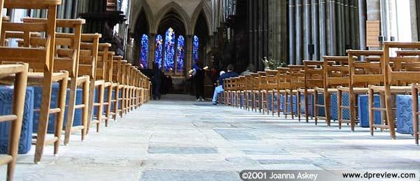
1 Image Based Rendering an overview Photographs We have tools that acquire and tools that display photographs at a convincing quality level 2 1


2 3 4 2


3 5 6 3


4 7 8 4
5 9 10 5


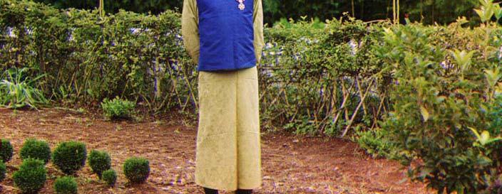
6 Photographs We have tools that acquire and tools that display photographs at a convincing quality level, for almost 100 years now 11 Sergei Mikhailovich Prokudin-Gorskii. A Settler's Family, ca


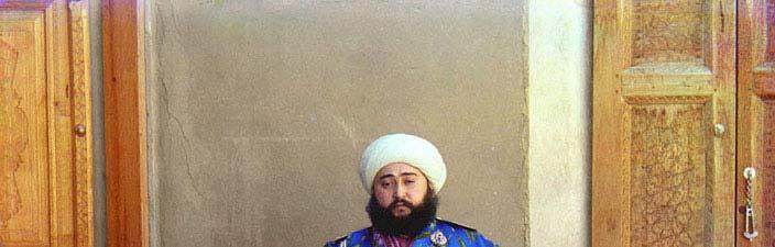


7 Sergei Mikhailovich Prokudin-Gorskii. Tea Factory in Chakva. Chinese Foreman Lau-Dzhen-Dzhau. ca Sergei Mikhailovich Prokudin-Gorskii. The Emir of Bukhara,
 with any")
 ρ = P( x, y, z, φ, ϕ, λ, t)")
8 RGB in early 1900 s 15 Plenoptic function Defines all the rays through any point in space (x, y, z) with any orientation (θ, φ) over all wavelenghts (λ) at any given moment in time (t) ρ = P( x, y, z, φ, ϕ, λ, t) 16 8
9 IBR summary Representation of plenoptic function implicit explicit geometric model texture ma apping pano oramas view mor rphing 3D image warping ray dat abases 17 Lightfield Lumigraph approach [Levoy96, Gortler96] Take all photographs you will ever need to display Model becomes database of rays Rendering becomes database querying 18 9
10 Introduction Overview Lightfield Lumigraph definition construction compression 19 Overview Introduction Lightfield Lumigraph definition construction compression 20 10

11 ρ = From 7D to 4D P ( x, y, z, φ, ϕ, λ, t) ) Static scene, t constant λ approximated with RGB consider only convex hull of objects, so the origin of the ray does not matter 21 4D Lightfield / Lumigraph 22 11

12 Discreet 4D Lightfield 23 Lightfield: set of images with COPs on regular grid 24 12


13 or Lightfield: set of images of a point seen at various angles 25 Depth correction of rays 26 13
14 Introduction Overview Lightfield Lumigraph definition construction compression 27 Overview Introduction Lightfield Lumigraph definition construction compression 28 14


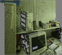
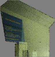
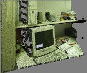
15 Construction from dense set of photographs 29 Construction from sparse set of photographs camera positions acquisition stage blue screening space carving 30 15
16 Filling in gaps using pull-push algorithm Pull phase low res levels are created gaps are shrunk Push phase gaps at high res levels are filled using low res levels 31 Overview Introduction Lightfield Lumigraph definition construction compression 32 16
17 Introduction Overview Lightfield Lumigraph definition construction compression 33 Compression Large size uncompressed: 1.125GB 125GB 32x32 (s, t) x 256x256 (u, v) x 6 faces x 3 B Compression jpeg + mpeg (200:1 to 6MB) or vector quantization + entropy encoding 34 17
18 Vector Quantization (VQ) Principle codebook made of codewords replace actual word with closest codeword Implementation training on representative set of words to derive best codebook compression: replacing word with index to closest codeword decompression: retrieve indexed codeword from codebook 35 Lightfield compression using VQ 36 18
![View morphing 37 Motivation rendering from images [Seitz96] Given left](/docs-images/78/78593048/images/19-0.jpg "image right image Create intermediate images simulates camera movement 38")
19 View morphing 37 Motivation rendering from images [Seitz96] Given left image right image Create intermediate images simulates camera movement 38 19
20 Previous work Panoramas ([Chen95], etc) user can look in any direction at few given locations Image-morphing ([Wolberg90], [Beier92], etc) linearly interpolated intermediate positions of features input: two images and correspondences output: metamorphosis of one image into other as sequence of intermediate images 39 Previous work limitations Panoramas ([Chen95], etc.) no camera translations allowed Image morphing ([Wolberg90], [Beier92], etc.) not shape-preserving image morphing is also a morph of the object to simulate rendering with morphing, the object should be rigid when camera moves 40 20
21 Introduction Image morphing View morphing image pre-warping image morphing image post-warping Overview 41 Introduction Image morphing View morphing image pre-warping image morphing image post-warping Overview 42 21
22 Image morphing 1. Correspondences 43 Image morphing 1. Correspondences 44 22
23 Image morphing 1. Correspondences 45 Image morphing 1. Correspondences 46 23
24 Image morphing P 0 P k P n 1. Correspondences 2. Linear interpolation k n k n k = (1 ) P0+ Pn P frame 0 frame k frame n 47 Image morphing Image morphing not shape preserving 48 24

25 Early IBR research Soft watch at moment of first explosion Salvador Dali Introduction Image morphing View morphing image pre-warping image morphing image post-warping Overview 50 25
26 Introduction Image morphing View morphing image pre-warping image morphing image post-warping Overview 51 View morphing Shape preserving morph Three step algorithm 1. Prewarp first and last images to parallel views 2. Image morph between prewarped images 3. Postwarp to interpolated view 52 26
27 Step 1: prewarp to parallel views P I 0 I 0p P 0p C 0 P 0 I n P n P np Inp Parallel views same image plane image plane parallel to segment connecting the two centers of projection Prewarp compute parallel views I 0p, I np rotate tt I 0 and di n to parallel lviews prewarp corrs. (P 0, P n ) -> (P op, P np ) C n 53 Step 2: morph parallel images P I 0 P 0 P n I n Shape preserving Use prewarped correspondences Interpolate C k from C 0 C n P 0p P kp I 0p P np I np C 0 C k C n 54 27


28 Step 3: Postwarping I 0 I 0p I n Postwarp morphed image create intermediate view C k is known interpolate view direction and tilt rotate morphed image to intermediate view C 0 C k C n 55 View morphing View morphing shape preserving 56 28
29 Overview Introduction Image morphing View morphing, more details image pre-warping image morphing image post-warping 57 Step 1: prewarp to parallel views P I 0 I n P 0p P 0 P n Parallel views use C 0 C n for x (a p vector) use (a 0 x b 0 ) x (a n x b n ) as y (-b p ) pick a p and b p to resemble a 0 b 0 as much as possible I 0p P np use same pixel size use wider field of view C 0 Inp C n 58 29
30 Step 1: prewarp to parallel views P I 0p I 0 P 0 P 0p C 0 I n P n P np Inp C n prewarping using texture mapping create polygon for image plane consider it texture mapped with the image itself render the scene from prewarped view if you go this path you will have to implement clipping with the COP plane you have texture mapping already alternative: prewarping using reprojection of rays look up all the rays of the prewarped view in the original view 59 Step 1: prewarp to parallel views P I 0 P 0 P 0p P n I n prewarping correspondences for all pairs of correspondence P 0 P n project P 0 on I 0p, computing P 0p project P n on I np, computing P np prewarped correspondence is P op P np I 0p P np C 0 Inp C n 60 30
31 Step 2: morph parallel images I 0p I 0 P 0 P 0p P kp C 0 C k P I n P n P np C n I np Image morphing use prewarped correspondences to compute a correspondence for all pixels in I 0p linearly interpolate I 0p to intermediate positions useful observation corresponding pixels are on same line in prewarped views preventing holes use larger footprint (ex 2x2) or linearly interpolate between consecutive samples or postprocess morphed image looking for background pixels and replacing them with neighboring values visibility artifacts collision of samples zbuffer on disparity holes morph I np to I kp use additional views 61 Step 3: Postwarping I 0 I 0p C 0 C k C n I n create intermediate view C k is known current view direction is a linear interpolation of the start and end view directions current up vector is a linear interpolation of the start and end up vectors rotate morphed image to intermediate view same as prewarping 62 31


32 Image-Based Rendering by Warping 63 Overview Introduction Depth extraction methods Reconstruction for IBRW Visibility without depth Sample selection 64 32
33 Introduction Overview comparison to other IBR methods 3D warping equation reconstruction 65 IBR by Warping (IBRW) Images enhanced with per-pixel pixel depth [McMillan95] u 1 v 1 P
34 IBR by Warping (IBRW) 1 u 1 1 C1P1 P = C 1 + ( c1 + u 1 a1 v 1b1 ) P ( + w w = C P 1 v 1 1/w 1 also called generalized disparity another notation δ(u 1, v 1 ) P1 C 1 67 IBR by Warping (IBRW) = C 1 + ( c 1 + u 1 a 1 + v 1 b 1 ) P ( + w P = C 2 + ( c2 + u2 a2 + v2b2) w2 u 1 P u 2 1 v 1 P 2 v 2 P1 C 1 C
35 u v 2 3D warping equations = = w w w 11 + w 12 u 1 + w 13 v 1 + w 14 v 31 + w + w 32 u u 1 + w + w δ ( u 1, 1 ) δ ( u, v ) δ ( u, v w31 + w32 u1 + w33 v1 + w34 δ ( u1, v1) u 1 P u 2 33 v 1 v + w + w ) v 1 v 2 C 1 C 2 69 A complete IBR method Façade system (coarse) geometric model needed Panoramas viewer confined to center of panorama View morphing correspondences needed IBRW rendering to arbitrary new views 70 35


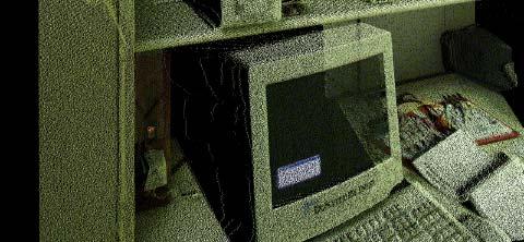
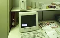
36 DeltaSphere - depth&color acquisition device Lars Nyland et al
37


38 75 Reconstructing by splatting Estimate shape and size of footprint of warped samples expensive to do accurately lower image quality if crudely approximated Samples are z-buffered 76 38


39 Introduction Overview Depth extraction methods Reconstruction for IBRW Visibility without depth Sample selection 77 Finding depth 78 39
40 Depth from stereo Overview Depth from structured light Depth from focus / defocus Laser rangefinders 79 Overview Depth from stereo Depth from structured light Depth from focus / defocus Laser rangefinders 80 40
41 Depth from stereo two cameras with known parameters infer 3D location of point seen in both images sub problem: correspondences for a point seen in the left image, find its projection in the right image u 1 P u 2 v 1 P 1 P2 v 2 C 1 C 2 81 Depth from stereo: déjà-vu math = C 1 + c1 + u1a1 v1b1 ) P ( + w = C 2 + c2 + u2 a2 v2b2) P ( + w 1 2 u 1 P u 2 unknowns are w 1 and w 2 overconstrained system v 1 P 1 P 2 v 2 the u 2v 2 coordinates of a point seen at u 1 v 1 are constrained to an epipolar line C 1 C
42 Epipolar line C 1, C 2, P 1 define a plane P 2 will be on that plane P 2 is also on the image plane 2 So P 2 will be on the line defined by the two planes intersection u 1 P u 2 v 1 P 2 v 2 P 1 C 1 C 2 83 Search for correspondences on epipolar line Reduces the dimensionality of the search space Walk on epipolar segment rather than search in entire image u 1 P u 2 v 1 P 2 v 2 P 1 C 1 C
43 Parallel views Preferred stereo configuration epipolar lines are horizontal, easy to search u 1 u 2 P v 1 C 1 v 1 C 2 85 Parallel views Limit search to epipolar segment from u 2 =u 1 (P is infinitely far away) to 0 (P is close) u 1 v 1 u 2 P C 1 v 1 C 2 u
44 Depth precision analysis 1/z linear with disparity (u 1 u 2 ) better depth resolution for nearby objects important to determine correspondences with subpixel accuracy u 1 u 2 P v 1 C 1 v 1 C 2 87 Overview Depth from stereo Depth from structured light Depth from focus / defocus Laser rangefinders 88 44
45 Depth from stereo Overview Depth from structured light Depth from focus / defocus Laser rangefinders 89 Depth from stereo problem Correspondences are difficult to find Structured light approach replace one camera with projector project easily detectable patterns establishing correspondences becomes a lot easier 90 45
46 Depth from structured light = C 1 + c1 + u1a1 v1b1 ) P ( + w P = C 2 + ( c2 + u2 a2 + v2b2) w2 C1 is a projector Projects a pattern centered at u 1 v 1 u Pattern center hits object scene at 1 P u 2 P Camera C 2 sees pattern at u 2 v 2, v easy to find v 2 1 3D location of P is determined P 1 P2 1 C 1 C
47 93 Depth from structured light challenges Associated with using projectors expensive, cannot be used outdoors, not portable Difficult to identify pattern I found a corner, which corner is it? Invasive, change the color of the scene one could use invisible light, IR 94 47
48 Depth from stereo Overview Depth from structured light Depth from focus / defocus Laser rangefinders 95 Overview Depth from stereo Depth from structured light Depth from focus / defocus Laser rangefinders 96 48
49 Depth of field Thin lenses rays through lens center (C) do not change direction rays parallel to optical axis go through focal point (F ) aperture object F C F image 97 For a given focal length, only objects that are at a certain depth are in focus Depth of field image plane aperture object F C F 98 49
50 Out of focus When object at different depth One point projects to several locations in the image Out of focus, blurred image image plane aperture object F C F 99 Move lens to focus for new depth Relationship between focus and depth can be exploited dto extract tdepth Focusing image plane aperture object F C F
51 Determine z for points in focus a hi a + = = f h z f image plane aperture a f object F h h i C F z 101 Depth from defocus Take images of a scene with various camera parameters Measuring defocus variation, infer range to objects Does not need to find the best focusing planes for the various objects Examples by Shree Nayar, Columbia U
52 Depth from stereo Overview Depth from structured light Depth from focus / defocus Laser rangefinders 103 Overview Depth from stereo Depth from structured light Depth from focus / defocus Laser rangefinders


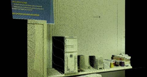
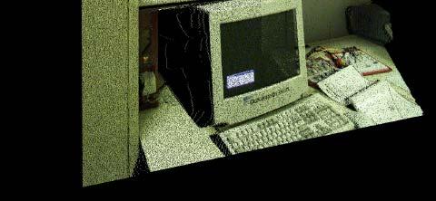
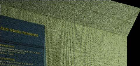
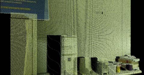
53 Laser range finders Send a laser beam to measure the distance like RADAR, measures time of flight 105 DeltaSphere - depth&color acquisition device Lars Nyland et al. courtesy 3 rd Tech Inc


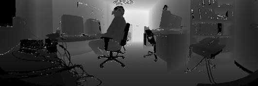
54 300 o x 300 o panorama this is the reflected light o x 300 o panorama this is the range light


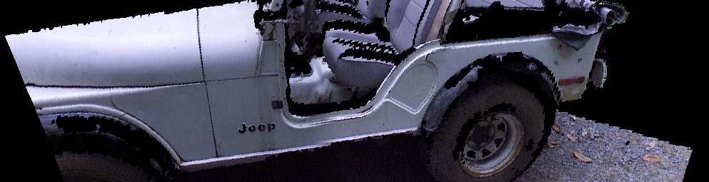
55 spherical range panoramas courtesy 3 rd Tech Inc. planar re-projection 109 Jeep one scan courtesy 3 rd Tech Inc


56 Jeep one scan courtesy 3 rd Tech Inc. 111 Complete Jeep model courtesy 3 rd Tech Inc
57 113 57
Image Processing: Motivation Rendering from Images. Related Work. Overview. Image Morphing Examples. Overview. View and Image Morphing CS334
 Motivation Rendering from Images Image rocessing: View and CS334 Given left image right image Create intermediate images simulates camera movement [Seitz96] Related Work anoramas ([Chen95/QuicktimeVR],
Image-Based Rendering
 Image-Based Rendering COS 526, Fall 2016 Thomas Funkhouser Acknowledgments: Dan Aliaga, Marc Levoy, Szymon Rusinkiewicz What is Image-Based Rendering? Definition 1: the use of photographic imagery to overcome
Image-Based Modeling and Rendering. Image-Based Modeling and Rendering. Final projects IBMR. What we have learnt so far. What IBMR is about
 Image-Based Modeling and Rendering Image-Based Modeling and Rendering MIT EECS 6.837 Frédo Durand and Seth Teller 1 Some slides courtesy of Leonard McMillan, Wojciech Matusik, Byong Mok Oh, Max Chen 2
A Review of Image- based Rendering Techniques Nisha 1, Vijaya Goel 2 1 Department of computer science, University of Delhi, Delhi, India
 A Review of Image- based Rendering Techniques Nisha 1, Vijaya Goel 2 1 Department of computer science, University of Delhi, Delhi, India Keshav Mahavidyalaya, University of Delhi, Delhi, India Abstract
Image Processing: 3D Image Warping. Spatial Transformations. Spatial Transformations. Affine Transformations. Affine Transformations CS334
 Image Warping Image rocessing: 3D Image Warping We can divide image arping into Simple spatial transformations (no per-pixel depth information) Full 3D transformations (needs per-pixel depth information)
Jingyi Yu CISC 849. Department of Computer and Information Science
 Digital Photography and Videos Jingyi Yu CISC 849 Light Fields, Lumigraph, and Image-based Rendering Pinhole Camera A camera captures a set of rays A pinhole camera captures a set of rays passing through
Light Fields. Johns Hopkins Department of Computer Science Course : Rendering Techniques, Professor: Jonathan Cohen
 Light Fields Light Fields By Levoy and Hanrahan, SIGGRAPH 96 Representation for sampled plenoptic function stores data about visible light at various positions and directions Created from set of images
Hybrid Rendering for Collaborative, Immersive Virtual Environments
 Hybrid Rendering for Collaborative, Immersive Virtual Environments Stephan Würmlin wuermlin@inf.ethz.ch Outline! Rendering techniques GBR, IBR and HR! From images to models! Novel view generation! Putting
Image Base Rendering: An Introduction
 Image Base Rendering: An Introduction Cliff Lindsay CS563 Spring 03, WPI 1. Introduction Up to this point, we have focused on showing 3D objects in the form of polygons. This is not the only approach to
Image-Based Modeling and Rendering
 Traditional Computer Graphics Image-Based Modeling and Rendering Thomas Funkhouser Princeton University COS 426 Guest Lecture Spring 2003 How would you model and render this scene? (Jensen) How about this
Stereo pairs from linear morphing
 Proc. of SPIE Vol. 3295, Stereoscopic Displays and Virtual Reality Systems V, ed. M T Bolas, S S Fisher, J O Merritt (Apr 1998) Copyright SPIE Stereo pairs from linear morphing David F. McAllister Multimedia
Image-based modeling (IBM) and image-based rendering (IBR)
 and image-based rendering (IBR)") Image-based modeling (IBM) and image-based rendering (IBR) CS 248 - Introduction to Computer Graphics Autumn quarter, 2005 Slides for December 8 lecture The graphics pipeline modeling animation rendering
Image-based modeling (IBM) and image-based rendering (IBR) CS 248 - Introduction to Computer Graphics Autumn quarter, 2005 Slides for December 8 lecture The graphics pipeline modeling animation rendering
Real-time Generation and Presentation of View-dependent Binocular Stereo Images Using a Sequence of Omnidirectional Images
 Real-time Generation and Presentation of View-dependent Binocular Stereo Images Using a Sequence of Omnidirectional Images Abstract This paper presents a new method to generate and present arbitrarily
Image-Based Rendering using Image-Warping Motivation and Background
 Image-Based Rendering using Image-Warping Motivation and Background Leonard McMillan LCS Computer Graphics Group MIT The field of three-dimensional computer graphics has long focused on the problem of
More and More on Light Fields. Last Lecture
 More and More on Light Fields Topics in Image-Based Modeling and Rendering CSE291 J00 Lecture 4 Last Lecture Re-review with emphasis on radiometry Mosaics & Quicktime VR The Plenoptic function The main
Modeling Light. On Simulating the Visual Experience
 Modeling Light 15-463: Rendering and Image Processing Alexei Efros On Simulating the Visual Experience Just feed the eyes the right data No one will know the difference! Philosophy: Ancient question: Does
Image Morphing. Application: Movie Special Effects. Application: Registration /Alignment. Image Cross-Dissolve
 Image Morphing Application: Movie Special Effects Morphing is turning one image into another (through a seamless transition) First movies with morphing Willow, 1988 Indiana Jones and the Last Crusade,
Image Transfer Methods. Satya Prakash Mallick Jan 28 th, 2003
 Image Transfer Methods Satya Prakash Mallick Jan 28 th, 2003 Objective Given two or more images of the same scene, the objective is to synthesize a novel view of the scene from a view point where there
The Light Field and Image-Based Rendering
 Lecture 11: The Light Field and Image-Based Rendering Visual Computing Systems Demo (movie) Royal Palace: Madrid, Spain Image-based rendering (IBR) So far in course: rendering = synthesizing an image from
A Warping-based Refinement of Lumigraphs
 A Warping-based Refinement of Lumigraphs Wolfgang Heidrich, Hartmut Schirmacher, Hendrik Kück, Hans-Peter Seidel Computer Graphics Group University of Erlangen heidrich,schirmacher,hkkueck,seidel@immd9.informatik.uni-erlangen.de
Stereo vision. Many slides adapted from Steve Seitz
 Stereo vision Many slides adapted from Steve Seitz What is stereo vision? Generic problem formulation: given several images of the same object or scene, compute a representation of its 3D shape What is
CSc Topics in Computer Graphics 3D Photography
 CSc 83010 Topics in Computer Graphics 3D Photography Tuesdays 11:45-1:45 1:45 Room 3305 Ioannis Stamos istamos@hunter.cuny.edu Office: 1090F, Hunter North (Entrance at 69 th bw/ / Park and Lexington Avenues)
3D Sensing and Reconstruction Readings: Ch 12: , Ch 13: ,
 3D Sensing and Reconstruction Readings: Ch 12: 12.5-6, Ch 13: 13.1-3, 13.9.4 Perspective Geometry Camera Model Stereo Triangulation 3D Reconstruction by Space Carving 3D Shape from X means getting 3D coordinates
BIL Computer Vision Apr 16, 2014
 BIL 719 - Computer Vision Apr 16, 2014 Binocular Stereo (cont d.), Structure from Motion Aykut Erdem Dept. of Computer Engineering Hacettepe University Slide credit: S. Lazebnik Basic stereo matching algorithm
Morphable 3D-Mosaics: a Hybrid Framework for Photorealistic Walkthroughs of Large Natural Environments
 Morphable 3D-Mosaics: a Hybrid Framework for Photorealistic Walkthroughs of Large Natural Environments Nikos Komodakis and Georgios Tziritas Computer Science Department, University of Crete E-mails: {komod,
Multiple View Geometry
 Multiple View Geometry Martin Quinn with a lot of slides stolen from Steve Seitz and Jianbo Shi 15-463: Computational Photography Alexei Efros, CMU, Fall 2007 Our Goal The Plenoptic Function P(θ,φ,λ,t,V
COSC579: Scene Geometry. Jeremy Bolton, PhD Assistant Teaching Professor
 COSC579: Scene Geometry Jeremy Bolton, PhD Assistant Teaching Professor Overview Linear Algebra Review Homogeneous vs non-homogeneous representations Projections and Transformations Scene Geometry The
A million pixels, a million polygons. Which is heavier? François X. Sillion. imagis* Grenoble, France
 A million pixels, a million polygons. Which is heavier? François X. Sillion imagis* Grenoble, France *A joint research project of CNRS, INRIA, INPG and UJF MAGIS Why this question? Evolution of processing
But, vision technology falls short. and so does graphics. Image Based Rendering. Ray. Constant radiance. time is fixed. 3D position 2D direction
 Computer Graphics -based rendering Output Michael F. Cohen Microsoft Research Synthetic Camera Model Computer Vision Combined Output Output Model Real Scene Synthetic Camera Model Real Cameras Real Scene
ECE-161C Cameras. Nuno Vasconcelos ECE Department, UCSD
 ECE-161C Cameras Nuno Vasconcelos ECE Department, UCSD Image formation all image understanding starts with understanding of image formation: projection of a scene from 3D world into image on 2D plane 2
Lecture 15: Image-Based Rendering and the Light Field. Kayvon Fatahalian CMU : Graphics and Imaging Architectures (Fall 2011)
") Lecture 15: Image-Based Rendering and the Light Field Kayvon Fatahalian CMU 15-869: Graphics and Imaging Architectures (Fall 2011) Demo (movie) Royal Palace: Madrid, Spain Image-based rendering (IBR) So
Lecture 15: Image-Based Rendering and the Light Field Kayvon Fatahalian CMU 15-869: Graphics and Imaging Architectures (Fall 2011) Demo (movie) Royal Palace: Madrid, Spain Image-based rendering (IBR) So
CSL 859: Advanced Computer Graphics. Dept of Computer Sc. & Engg. IIT Delhi
 CSL 859: Advanced Computer Graphics Dept of Computer Sc. & Engg. IIT Delhi Point Based Representation Point sampling of Surface Mesh construction, or Mesh-less Often come from laser scanning Or even natural
Volumetric Scene Reconstruction from Multiple Views
 Volumetric Scene Reconstruction from Multiple Views Chuck Dyer University of Wisconsin dyer@cs cs.wisc.edu www.cs cs.wisc.edu/~dyer Image-Based Scene Reconstruction Goal Automatic construction of photo-realistic
But First: Multi-View Projective Geometry
 View Morphing (Seitz & Dyer, SIGGRAPH 96) Virtual Camera Photograph Morphed View View interpolation (ala McMillan) but no depth no camera information Photograph But First: Multi-View Projective Geometry
Lecture 19: Depth Cameras. Visual Computing Systems CMU , Fall 2013
 Lecture 19: Depth Cameras Visual Computing Systems Continuing theme: computational photography Cameras capture light, then extensive processing produces the desired image Today: - Capturing scene depth
Image-Based Rendering. Johns Hopkins Department of Computer Science Course : Rendering Techniques, Professor: Jonathan Cohen
 Image-Based Rendering Image-Based Rendering What is it? Still a difficult question to answer Uses images (photometric( info) as key component of model representation What s Good about IBR Model acquisition
Introduction to 3D Machine Vision
 Introduction to 3D Machine Vision 1 Many methods for 3D machine vision Use Triangulation (Geometry) to Determine the Depth of an Object By Different Methods: Single Line Laser Scan Stereo Triangulation
DD2423 Image Analysis and Computer Vision IMAGE FORMATION. Computational Vision and Active Perception School of Computer Science and Communication
 DD2423 Image Analysis and Computer Vision IMAGE FORMATION Mårten Björkman Computational Vision and Active Perception School of Computer Science and Communication November 8, 2013 1 Image formation Goal:
Multi-View Stereo for Static and Dynamic Scenes
 Multi-View Stereo for Static and Dynamic Scenes Wolfgang Burgard Jan 6, 2010 Main references Yasutaka Furukawa and Jean Ponce, Accurate, Dense and Robust Multi-View Stereopsis, 2007 C.L. Zitnick, S.B.
IMAGE-BASED RENDERING TECHNIQUES FOR APPLICATION IN VIRTUAL ENVIRONMENTS
 IMAGE-BASED RENDERING TECHNIQUES FOR APPLICATION IN VIRTUAL ENVIRONMENTS Xiaoyong Sun A Thesis submitted to the Faculty of Graduate and Postdoctoral Studies in partial fulfillment of the requirements for
Computational Photography
 Computational Photography Matthias Zwicker University of Bern Fall 2010 Today Light fields Introduction Light fields Signal processing analysis Light field cameras Application Introduction Pinhole camera
Image-Based Rendering and Modeling. IBR Approaches for View Synthesis
 Image-Based Rendering and Modeling l Image-based rendering (IBR): A scene is represented as a collection of images l 3D model-based rendering (MBR): A scene is represented by a 3D model plus texture maps
Optimizing an Inverse Warper
 Optimizing an Inverse Warper by Robert W. Marcato, Jr. Submitted to the Department of Electrical Engineering and Computer Science in Partial Fulfillment of the Requirements for the Degrees of Bachelor
Image or Object? Is this real?
 Image or Object? Michael F. Cohen Microsoft Is this real? Photo by Patrick Jennings (patrick@synaptic.bc.ca), Copyright 1995, 96, 97 Whistler B. C. Canada Modeling, Rendering, and Lighting 1 A mental model?
CS 684 Fall 2005 Image-based Modeling and Rendering. Ruigang Yang
 CS 684 Fall 2005 Image-based Modeling and Rendering Ruigang Yang Administrivia Classes: Monday and Wednesday, 4:00-5:15 PM Instructor: Ruigang Yang ryang@cs.uky.edu Office Hour: Robotics 514D, MW 1500-1600
Range Imaging Through Triangulation. Range Imaging Through Triangulation. Range Imaging Through Triangulation. Range Imaging Through Triangulation
 Obviously, this is a very slow process and not suitable for dynamic scenes. To speed things up, we can use a laser that projects a vertical line of light onto the scene. This laser rotates around its vertical
Modeling Light. Michal Havlik : Computational Photography Alexei Efros, CMU, Fall 2007
 Modeling Light Michal Havlik 15-463: Computational Photography Alexei Efros, CMU, Fall 2007 The Plenoptic Function Figure by Leonard McMillan Q: What is the set of all things that we can ever see? A: The
Overview of Active Vision Techniques
 SIGGRAPH 99 Course on 3D Photography Overview of Active Vision Techniques Brian Curless University of Washington Overview Introduction Active vision techniques Imaging radar Triangulation Moire Active
Image-Based Rendering and Light Fields
 CS194-13: Advanced Computer Graphics Lecture #9 Image-Based Rendering University of California Berkeley Image-Based Rendering and Light Fields Lecture #9: Wednesday, September 30th 2009 Lecturer: Ravi
Multi-view stereo. Many slides adapted from S. Seitz
 Multi-view stereo Many slides adapted from S. Seitz Beyond two-view stereo The third eye can be used for verification Multiple-baseline stereo Pick a reference image, and slide the corresponding window
Acquisition and Visualization of Colored 3D Objects
 Acquisition and Visualization of Colored 3D Objects Kari Pulli Stanford University Stanford, CA, U.S.A kapu@cs.stanford.edu Habib Abi-Rached, Tom Duchamp, Linda G. Shapiro and Werner Stuetzle University
Image-Bas ed R endering Using Image Warping. Conventional 3-D Graphics
 Image-Bas ed R endering Using Image Warping Leonard McMillan LCS Computer Graphics Group MIT Conventional 3-D Graphics Simulation Computer Vis ion Analys is T he Image-Bas ed Approach T rans formation
Rendering. Converting a 3D scene to a 2D image. Camera. Light. Rendering. View Plane
 Rendering Pipeline Rendering Converting a 3D scene to a 2D image Rendering Light Camera 3D Model View Plane Rendering Converting a 3D scene to a 2D image Basic rendering tasks: Modeling: creating the world
Computer Vision for Computer Graphics
 Computer Vision for Computer Graphics Mark Borg Computer Vision & Computer Graphics I Computer Vision Understanding the content of an image (normaly by creating a model of the observed scene) Computer
Triangle Rasterization
 Triangle Rasterization Computer Graphics COMP 770 (236) Spring 2007 Instructor: Brandon Lloyd 2/07/07 1 From last time Lines and planes Culling View frustum culling Back-face culling Occlusion culling
DEPTH, STEREO AND FOCUS WITH LIGHT-FIELD CAMERAS
 DEPTH, STEREO AND FOCUS WITH LIGHT-FIELD CAMERAS CINEC 2014 Frederik Zilly, Head of Group Computational Imaging & Algorithms Moving Picture Technologies Department, Fraunhofer IIS Fraunhofer, Frederik
3D Rendering and Ray Casting
 3D Rendering and Ray Casting Michael Kazhdan (601.457/657) HB Ch. 13.7, 14.6 FvDFH 15.5, 15.10 Rendering Generate an image from geometric primitives Rendering Geometric Primitives (3D) Raster Image (2D)
Reminder: Lecture 20: The Eight-Point Algorithm. Essential/Fundamental Matrix. E/F Matrix Summary. Computing F. Computing F from Point Matches
 Reminder: Lecture 20: The Eight-Point Algorithm F = -0.00310695-0.0025646 2.96584-0.028094-0.00771621 56.3813 13.1905-29.2007-9999.79 Readings T&V 7.3 and 7.4 Essential/Fundamental Matrix E/F Matrix Summary
Image Based Reconstruction II
 Image Based Reconstruction II Qixing Huang Feb. 2 th 2017 Slide Credit: Yasutaka Furukawa Image-Based Geometry Reconstruction Pipeline Last Lecture: Multi-View SFM Multi-View SFM This Lecture: Multi-View
CS664 Lecture #19: Layers, RANSAC, panoramas, epipolar geometry
 CS664 Lecture #19: Layers, RANSAC, panoramas, epipolar geometry Some material taken from: David Lowe, UBC Jiri Matas, CMP Prague http://cmp.felk.cvut.cz/~matas/papers/presentations/matas_beyondransac_cvprac05.ppt
Image-Based Rendering. Johns Hopkins Department of Computer Science Course : Rendering Techniques, Professor: Jonathan Cohen
 Image-Based Rendering Image-Based Rendering What is it? Still a difficult question to answer Uses images (photometric( info) as key component of model representation What s Good about IBR Model acquisition
Computer Vision. 3D acquisition
 è Computer 3D acquisition Acknowledgement Courtesy of Prof. Luc Van Gool 3D acquisition taxonomy s image cannot currently be displayed. 3D acquisition methods Thi passive active uni-directional multi-directional
Topics and things to know about them:
 Practice Final CMSC 427 Distributed Tuesday, December 11, 2007 Review Session, Monday, December 17, 5:00pm, 4424 AV Williams Final: 10:30 AM Wednesday, December 19, 2007 General Guidelines: The final will
Image-Based Rendering. Image-Based Rendering
 Image-Based Rendering Image-Based Rendering What is it? Still a difficult question to answer Uses images (photometric info) as key component of model representation 1 What s Good about IBR Model acquisition
Image-Based Modeling and Rendering
 Image-Based Modeling and Rendering Richard Szeliski Microsoft Research IPAM Graduate Summer School: Computer Vision July 26, 2013 How far have we come? Light Fields / Lumigraph - 1996 Richard Szeliski
A million pixels, a million polygons: which is heavier?
 A million pixels, a million polygons: which is heavier? François X. Sillion To cite this version: François X. Sillion. A million pixels, a million polygons: which is heavier?. Eurographics 97, Sep 1997,
3D Rendering and Ray Casting
 3D Rendering and Ray Casting Michael Kazhdan (601.457/657) HB Ch. 13.7, 14.6 FvDFH 15.5, 15.10 Rendering Generate an image from geometric primitives Rendering Geometric Primitives (3D) Raster Image (2D)
PERFORMANCE CAPTURE FROM SPARSE MULTI-VIEW VIDEO
 Stefan Krauß, Juliane Hüttl SE, SoSe 2011, HU-Berlin PERFORMANCE CAPTURE FROM SPARSE MULTI-VIEW VIDEO 1 Uses of Motion/Performance Capture movies games, virtual environments biomechanics, sports science,
Stereo. 11/02/2012 CS129, Brown James Hays. Slides by Kristen Grauman
 Stereo 11/02/2012 CS129, Brown James Hays Slides by Kristen Grauman Multiple views Multi-view geometry, matching, invariant features, stereo vision Lowe Hartley and Zisserman Why multiple views? Structure
3D Computer Vision. Depth Cameras. Prof. Didier Stricker. Oliver Wasenmüller
 3D Computer Vision Depth Cameras Prof. Didier Stricker Oliver Wasenmüller Kaiserlautern University http://ags.cs.uni-kl.de/ DFKI Deutsches Forschungszentrum für Künstliche Intelligenz http://av.dfki.de
Capturing light. Source: A. Efros
 Capturing light Source: A. Efros Review Pinhole projection models What are vanishing points and vanishing lines? What is orthographic projection? How can we approximate orthographic projection? Lenses
Ray tracing based fast refraction method for an object seen through a cylindrical glass
 20th International Congress on Modelling and Simulation, Adelaide, Australia, 1 6 December 2013 www.mssanz.org.au/modsim2013 Ray tracing based fast refraction method for an object seen through a cylindrical
L2 Data Acquisition. Mechanical measurement (CMM) Structured light Range images Shape from shading Other methods
 Structured light Range images Shape from shading Other methods") L2 Data Acquisition Mechanical measurement (CMM) Structured light Range images Shape from shading Other methods 1 Coordinate Measurement Machine Touch based Slow Sparse Data Complex planning Accurate 2
L2 Data Acquisition Mechanical measurement (CMM) Structured light Range images Shape from shading Other methods 1 Coordinate Measurement Machine Touch based Slow Sparse Data Complex planning Accurate 2
IRW: An Incremental Representation for Image-Based Walkthroughs
 IRW: An Incremental Representation for Image-Based Walkthroughs David Gotz gotz@cs.unc.edu Ketan Mayer-Patel kmp@cs.unc.edu University of North Carolina at Chapel Hill CB #3175, Sitterson Hall Chapel Hill,
Model-Based Stereo. Chapter Motivation. The modeling system described in Chapter 5 allows the user to create a basic model of a
 96 Chapter 7 Model-Based Stereo 7.1 Motivation The modeling system described in Chapter 5 allows the user to create a basic model of a scene, but in general the scene will have additional geometric detail
There are many cues in monocular vision which suggests that vision in stereo starts very early from two similar 2D images. Lets see a few...
 STEREO VISION The slides are from several sources through James Hays (Brown); Srinivasa Narasimhan (CMU); Silvio Savarese (U. of Michigan); Bill Freeman and Antonio Torralba (MIT), including their own
Focal stacks and lightfields
 Focal stacks and lightfields http://graphics.cs.cmu.edu/courses/15-463 15-463, 15-663, 15-862 Computational Photography Fall 2018, Lecture 11 Course announcements Homework 3 is out. - Due October 12 th.
Modeling Light. Slides from Alexei A. Efros and others
 Project 3 Results http://www.cs.brown.edu/courses/cs129/results/proj3/jcmace/ http://www.cs.brown.edu/courses/cs129/results/proj3/damoreno/ http://www.cs.brown.edu/courses/cs129/results/proj3/taox/ Stereo
5LSH0 Advanced Topics Video & Analysis
 1 Multiview 3D video / Outline 2 Advanced Topics Multimedia Video (5LSH0), Module 02 3D Geometry, 3D Multiview Video Coding & Rendering Peter H.N. de With, Sveta Zinger & Y. Morvan ( p.h.n.de.with@tue.nl
Multiple Views Geometry
 Multiple Views Geometry Subhashis Banerjee Dept. Computer Science and Engineering IIT Delhi email: suban@cse.iitd.ac.in January 2, 28 Epipolar geometry Fundamental geometric relationship between two perspective
Computational Photography
 Computational Photography Photography and Imaging Michael S. Brown Brown - 1 Part 1 Overview Photography Preliminaries Traditional Film Imaging (Camera) Part 2 General Imaging 5D Plenoptic Function (McMillan)
EE795: Computer Vision and Intelligent Systems
 EE795: Computer Vision and Intelligent Systems Spring 2012 TTh 17:30-18:45 FDH 204 Lecture 12 130228 http://www.ee.unlv.edu/~b1morris/ecg795/ 2 Outline Review Panoramas, Mosaics, Stitching Two View Geometry
Stereo CSE 576. Ali Farhadi. Several slides from Larry Zitnick and Steve Seitz
 Stereo CSE 576 Ali Farhadi Several slides from Larry Zitnick and Steve Seitz Why do we perceive depth? What do humans use as depth cues? Motion Convergence When watching an object close to us, our eyes
Image-Based Deformation of Objects in Real Scenes
 Image-Based Deformation of Objects in Real Scenes Han-Vit Chung and In-Kwon Lee Dept. of Computer Science, Yonsei University sharpguy@cs.yonsei.ac.kr, iklee@yonsei.ac.kr Abstract. We present a new method
Depth. Chapter Stereo Imaging
 Chapter 11 Depth Calculating the distance of various points in the scene relative to the position of the camera is one of the important tasks for a computer vision system. A common method for extracting
lecture 10 - depth from blur, binocular stereo
 This lecture carries forward some of the topics from early in the course, namely defocus blur and binocular disparity. The main emphasis here will be on the information these cues carry about depth, rather
Computer Graphics. Bing-Yu Chen National Taiwan University The University of Tokyo
 Computer Graphics Bing-Yu Chen National Taiwan University The University of Tokyo Hidden-Surface Removal Back-Face Culling The Depth-Sort Algorithm Binary Space-Partitioning Trees The z-buffer Algorithm
calibrated coordinates Linear transformation pixel coordinates
 1 calibrated coordinates Linear transformation pixel coordinates 2 Calibration with a rig Uncalibrated epipolar geometry Ambiguities in image formation Stratified reconstruction Autocalibration with partial
Processing 3D Surface Data
 Processing 3D Surface Data Computer Animation and Visualisation Lecture 12 Institute for Perception, Action & Behaviour School of Informatics 3D Surfaces 1 3D surface data... where from? Iso-surfacing
The Viewing Pipeline Coordinate Systems
 Overview Interactive Graphics System Model Graphics Pipeline Coordinate Systems Modeling Transforms Cameras and Viewing Transform Lighting and Shading Color Rendering Visible Surface Algorithms Rasterization
Midterm Examination CS 534: Computational Photography
 Midterm Examination CS 534: Computational Photography November 3, 2016 NAME: Problem Score Max Score 1 6 2 8 3 9 4 12 5 4 6 13 7 7 8 6 9 9 10 6 11 14 12 6 Total 100 1 of 8 1. [6] (a) [3] What camera setting(s)
Traditional pipeline for shape capture. Active range scanning. New pipeline for shape capture. Draw contours on model. Digitize lines with touch probe
 Traditional pipeline for shape capture Draw contours on model Active range scanning Digitize lines with touch probe Fit smooth surfaces CAD/CAM Texturing and animation 1 2 New pipeline for shape capture
DEVELOPMENT OF REAL TIME 3-D MEASUREMENT SYSTEM USING INTENSITY RATIO METHOD
 DEVELOPMENT OF REAL TIME 3-D MEASUREMENT SYSTEM USING INTENSITY RATIO METHOD Takeo MIYASAKA and Kazuo ARAKI Graduate School of Computer and Cognitive Sciences, Chukyo University, Japan miyasaka@grad.sccs.chukto-u.ac.jp,
Introduction to 3D Concepts
 PART I Introduction to 3D Concepts Chapter 1 Scene... 3 Chapter 2 Rendering: OpenGL (OGL) and Adobe Ray Tracer (ART)...19 1 CHAPTER 1 Scene s0010 1.1. The 3D Scene p0010 A typical 3D scene has several
Challenges and advances in interactive modeling
 Challenges and advances in interactive modeling Voicu Popescu, Elisha Sacks, Aliasgar Ganiji Computer Sciences Department, Purdue University, 250 N University Street, West Lafayette, IN 47907-2066 ABSTRACT
3-D Shape Reconstruction from Light Fields Using Voxel Back-Projection
 3-D Shape Reconstruction from Light Fields Using Voxel Back-Projection Peter Eisert, Eckehard Steinbach, and Bernd Girod Telecommunications Laboratory, University of Erlangen-Nuremberg Cauerstrasse 7,
High-Quality Interactive Lumigraph Rendering Through Warping
 High-Quality Interactive Lumigraph Rendering Through Warping Hartmut Schirmacher, Wolfgang Heidrich, and Hans-Peter Seidel Max-Planck-Institut für Informatik Saarbrücken, Germany http://www.mpi-sb.mpg.de
Multimedia Technology CHAPTER 4. Video and Animation
 CHAPTER 4 Video and Animation - Both video and animation give us a sense of motion. They exploit some properties of human eye s ability of viewing pictures. - Motion video is the element of multimedia
3D Sensing. 3D Shape from X. Perspective Geometry. Camera Model. Camera Calibration. General Stereo Triangulation.
 3D Sensing 3D Shape from X Perspective Geometry Camera Model Camera Calibration General Stereo Triangulation 3D Reconstruction 3D Shape from X shading silhouette texture stereo light striping motion mainly
Page 1. Area-Subdivision Algorithms z-buffer Algorithm List Priority Algorithms BSP (Binary Space Partitioning Tree) Scan-line Algorithms
 Scan-line Algorithms") Visible Surface Determination Visibility Culling Area-Subdivision Algorithms z-buffer Algorithm List Priority Algorithms BSP (Binary Space Partitioning Tree) Scan-line Algorithms Divide-and-conquer strategy:
Visible Surface Determination Visibility Culling Area-Subdivision Algorithms z-buffer Algorithm List Priority Algorithms BSP (Binary Space Partitioning Tree) Scan-line Algorithms Divide-and-conquer strategy: