The MICROPROCESSOR PRINCIPLES AND APPLICATIONS Lab 7
|
|
|
- Monica Cox
- 5 years ago
- Views:
Transcription

1 The MICROPROCESSOR PRINCIPLES AND APPLICATIONS Lab 7 Timer, USART Cheng-Chien Su 蘇正建 Home Automation, Networking, and Entertainment Lab Dept. of Computer Science and Information Engineering National Cheng Kung University, TAIWAN
2 Outline Timer0 Introduction & Operation Timer1 Introduction & Operation C18 C Libraries of Timer USART Introduction & Operation C18 C Libraries of USART Lab Reference National Cheng Kung University, TAIWAN 2
3 Timer0 Introduction The Timer0 module incorporates the following features: Software selectable operation as a timer or counter in both 8-bit or 16-bit modes Readable and writable registers Dedicated 8-bit, software programmable prescaler Selectable clock source (internal or external) Edge select for external clock Interrupt-on-overflow National Cheng Kung University, TAIWAN 3
4 Timer0 Introduction Block Diagram The T0CON register controls all aspects of the module s operation, including the prescale selection. It is both readable and writable. A simplified block diagram of the Timer0 module in 8-bit mode is shown in figure. National Cheng Kung University, TAIWAN 4
5 Timer0 Introduction T0CON Register National Cheng Kung University, TAIWAN 5
6 Timer0 Introduction Prescaler An 8-bit counter is available as a prescaler for the Timer0 module. Its value is set by the PSA and T0PS2:T0PS0 bits (T0CON<3:0>) which determine the prescaler assignment and prescale ratio. Clearing the PSA bit assigns the prescaler to the Timer0 module. When it is assigned, prescale values from 1:2 through 1:256 in power-of-2 increments are selectable. National Cheng Kung University, TAIWAN 6
7 Timer0 Operation Timer0 can operate as either a timer or a counter; the mode is selected with the T0CS bit (T0CON<5>). In Timer mode (T0CS = 0), the module increments on every clock by default unless a different prescaler value is selected. The user can work around this by writing an adjusted value to the TMR0 register. The Counter mode is selected by setting the T0CS bit (= 1). In this mode, Timer0 increments either on every rising or falling edge of pin RA4/T0CKI. The incrementing edge is determined by the Timer0 Source Edge Select bit, T0SE (T0CON<4>); clearing this bit selects the rising edge. National Cheng Kung University, TAIWAN 7
8 Timer0 Operation Interrupt The TMR0 interrupt is generated when the TMR0 register overflows from FFh to 00h in 8-bit mode, or from FFFFh to 0000h in 16-bit mode. This overflow sets the TMR0IF flag bit. The interrupt can be masked by clearing the TMR0IE bit (INTCON<5>). Before re-enabling the interrupt, the TMR0IF bit must be cleared in software by the Interrupt Service Routine. Since Timer0 is shut down in Sleep mode, the TMR0 interrupt cannot awaken the processor from Sleep. National Cheng Kung University, TAIWAN 8
9 Timer1 Introduction The Timer1 timer/counter module incorporates these features: Software selectable operation as a 16-bit timer or counter Readable and writable 8-bit registers (TMR1H and TMR1L) selectable clock source (internal or external) with device clock or Timer1 oscillator internal options Interrupt-on-overflow Reset on CCP Special Event Trigger Device clock status flag (T1RUN) National Cheng Kung University, TAIWAN 9
10 Timer1 Introduction Block Diagram National Cheng Kung University, TAIWAN 10
11 Timer1 Introduction T1CON Register National Cheng Kung University, TAIWAN 11
12 C18 C Libraries of Timerx Overall Timer Functions: the timer peripherals are supported with the following functions: CloseTimerx OpenTimerx ReadTimerx WriteTimerx National Cheng Kung University, TAIWAN 12
13 C18 C Libraries of Timer OpenTimer0 OpenTimer0: Configure and enable timer0. Include: timers.h Prototype: void OpenTimer0( unsigned char config ); Arguments: config Enable Timer0 Interrupt: TIMER_INT_ON Interrupt enabled TIMER_INT_OFF Interrupt disabled Timer Width: T0_8BIT 8-bit mode T0_16BIT 16-bit mode Clock Source: T0_SOURCE_EXT External clock source (I/O pin) T0_SOURCE_INT Internal clock source (TOSC) External Clock Trigger (for T0_SOURCE_EXT): T0_EDGE_FALL External clock on falling edge T0_EDGE_RISE External clock on rising edge Prescale Value: T0_PS_1_1 1:1 prescale T0_PS_1_2 1:2 prescale T0_PS_1_256 1:256 prescale Remarks: This function configures timer0 according to the options specified and then enables it. Code Example: OpenTimer0( TIMER_INT_OFF & T0_8BIT & T0_SOURCE_INT & T0_PS_1_32 ); National Cheng Kung University, TAIWAN 13
14 C18 C Libraries of Timer OpenTimer1 OpenTimer1: Configure and enable timer1. Include: timers.h Prototype: void OpenTimer1( unsigned char config ); Arguments: config Enable Timer1 Interrupt: TIMER_INT_ON Interrupt enabled TIMER_INT_OFF Interrupt disabled Timer Width: T1_8BIT_RW 8-bit mode T1_16BIT_RW 16-bit mode Clock Source: T1_SOURCE_EXT External clock source (I/O pin) T1_SOURCE_INT Internal clock source (TOSC) Prescaler: T1_PS_1_1 1:1 prescale T1_PS_1_2 1:2 prescale T1_PS_1_4 1:4 prescale T1_PS_1_8 1:8 prescale Oscillator Use: T1_OSC1EN_ON Enable Timer1 oscillator T1_OSC1EN_OFF Disable Timer1 oscillator Synchronize Clock Input: T1_SYNC_EXT_ON Sync external clock input T1_SYNC_EXT_OFF Don t sync external clock input Remarks: This function configures timer1 according to the options specified and then enables it. Code Example: OpenTimer1( TIMER_INT_ON & T1_8BIT_RW & T1_SOURCE_EXT & T1_PS_1_1 & T1_OSC1EN_OFF & T1_SYNC_EXT_OFF ); National Cheng Kung University, TAIWAN 14
15 C18 C Libraries of Timer WriteTimer0 WriteTimer0: Write a value into the specified timer. Include: timers.h Prototype: void WriteTimer0( unsigned int timer ); Arguments: timer The value that will be loaded into the specified timer. Remarks: These functions write a value to the respective timer register(s):tmr0l,tmr0h Code Example: WriteTimer0( ); National Cheng Kung University, TAIWAN 15
16 C18 C Libraries of Timer ReadTimer0 ReadTimer0: Read the value of the specified timer. Include: timers.h Prototype: unsigned int ReadTimer0( void ); Remarks: These functions read the value of the respective timer register(s): TMR0L,TMR0H Return Value: The current value of the timer. Note: When using a timer in 8-bit mode that may be configured in 16-bit mode (e.g., timer0), the upper byte is not ensured to be zero. The user may wish to cast the result to a char for correct results. Code Example: unsigned int result; result = (unsigned char) ReadTimer0(); National Cheng Kung University, TAIWAN 16
17 C18 C Libraries of Timer CloseTimer0 CloseTimer0: Disable the specified timer. Include: timers.h Prototype: void CloseTimer0( void ); Remarks: This function disables the interrupt and the specified timer. National Cheng Kung University, TAIWAN 17
18 C18 C Libraries of Timer Example #include <p18c4520.h> #include <timers.h> #include <stdlib.h> void main( void ){ int result; char str[7]; // configure timer0 OpenTimer0( TIMER_INT_OFF & T0_SOURCE_INT & T0_PS_1_32 ); TRISD = 0; while( 1 ) { while(! PORTBbits.RB3 ); result = ReadTimer0(); if( result > 0xc000 ) break; WriteTimer0( 0 ); // wait for RB3 high // read timer // exit loop if value // is out of range // restart timer } PORTD = (unsinged char) result; } CloseTimer0(); // close modules National Cheng Kung University, TAIWAN 18
19 USART Introduction The Enhanced Universal Synchronous Asynchronous Receiver Transmitter (USART) module is one of the two serial I/O modules. The USART can be configured A full-duplex asynchronous system, such as personal computers, etc. A half-duplex, synchronous system, such as serial EEPROMs, etc. The Enhanced USART module implements additional features: automatic baud rate detection and calibration automatic wake-up on Sync Break reception 12-bit Break character transmit. National Cheng Kung University, TAIWAN 19
20 USART Introduction (cont ) The USART can be configured in the following modes: Asynchronous (full duplex) with: Auto-wake-up on character reception Auto-baud calibration 12-bit Break character transmission Synchronous Master (half duplex) with selectable clock polarity Synchronous Slave (half duplex) with selectable clock polarity National Cheng Kung University, TAIWAN 20
21 USART Introduction (cont ) The pins of the Enhanced USART are multiplexed with PORTC. In order to configure RC6/TX/CK and RC7/RX/DT as an USART: bit SPEN (RCSTA<7>) must be set (= 1) bit TRISC<7> must be set (= 1) bit TRISC<6> must be set (= 1) The operation of the Enhanced USART module is controlled through three registers: Transmit Status and Control (TXSTA) Receive Status and Control (RCSTA) Baud Rate Control (BAUDCON) National Cheng Kung University, TAIWAN 21
22 Registers of USART TXSTA Register National Cheng Kung University, TAIWAN 22
23 Registers of USART RCSTA Register National Cheng Kung University, TAIWAN 23
24 Registers of USART BAUDCON Register National Cheng Kung University, TAIWAN 24
25 USART Operation Baud Rate Generator (BRG) The BRG is a dedicated, 8-bit or 16-bit generator that supports both the Asynchronous and Synchronous modes of the USART. By default, the BRG operates in 8-bit mode; setting the BRG16 bit (BAUDCON<3>) selects 16-bit mode. The SPBRGH:SPBRG register pair controls the period of a free-running timer. In Asynchronous mode, bits, BRGH (TXSTA<2>) and BRG16 (BAUDCON<3>), also control the baud rate. In Synchronous mode, BRGH is ignored. National Cheng Kung University, TAIWAN 25
26 USART Operation Baud Rate Generator (BRG) Example Lookup table Baud Rate Formula National Cheng Kung University, TAIWAN 26
27 USART Operation Asynchronous Mode The Asynchronous mode of operation is selected by clearing the SYNC bit (TXSTA<4>). In this mode, the USART uses standard Non- Return-to-Zero (NRZ) format (one Start bit, eight or nine data bits and one Stop bit). The USART transmits and receives the LSB first. The USART s transmitter and receiver are functionally independent but use the same data format and baud rate. Parity is not supported by the hardware but can be implemented in software and stored as the 9th data bit. National Cheng Kung University, TAIWAN 27
28 USART Operation Asynchronous Transmitter USART Asynchronous Transmitter The heart of the transmitter is the Transmit (Serial) Shift Register (TSR). The Shift register obtains its data from the Read/Write Transmit Buffer register, TXREG. The TXREG register is loaded with data in software. The TSR register is not loaded until the Stop bit has been transmitted from the previous load. As soon as the Stop bit is transmitted, the TSR is loaded with new data from the TXREG register (if available). National Cheng Kung University, TAIWAN 28
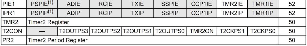
29 USART Operation Asynchronous Transmitter This interrupt can be enabled or disabled by setting or clearing the interrupt enable bit, TXIE (PIE1<4>). TRMT is a read-only bit which is set when the TSR register is empty. National Cheng Kung University, TAIWAN 29
30 USART Operation Asynchronous Transmitter To set up an Asynchronous Transmission: 1. Initialize the SPBRGH:SPBRG registers for the appropriate baud rate. Set or clear the BRGH and BRG16 bits, as required, to achieve the desired baud rate. 2. Enable the asynchronous serial port, SYNC=0 and SPEN=1. 3. If interrupts are desired, TXIE=1. 4. If 9-bit transmission is desired, TX9=1. 5. Enable the transmission by setting bit, TXEN, which will also set bit, TXIF. 6. If 9-bit transmission is selected, the ninth bit should be loaded in bit, TX9D. 7. Load data to the TXREG register (starts transmission). 8. If using interrupts, ensure that the GIE and PEIE bits in the INTCON register (INTCON<7:6>) are set. National Cheng Kung University, TAIWAN 30
31 USART Operation Asynchronous Receiver USART Asynchronous Receiver The data is received on the RX pin and drives the data recovery block. The data recovery block is actually a high-speed shifter operating at x16 times the baud rate, whereas the main receive serial shifter operates at the bit rate or at FOSC. This mode would typically be used in RS-232 systems. National Cheng Kung University, TAIWAN 31
32 USART Operation Asynchronous Receiver To set up an Asynchronous Reception: 1. Initialize the SPBRGH:SPBRG registers for the appropriate baud rate. Set or clear the BRGH and BRG16 bits, as required, to achieve the desired baud rate. 2. Enable the asynchronous serial port, SYNC=0 and SPEN=1. 3. If interrupts are desired, RCIE=1. 4. If 9-bit reception is desired, RX9=1. 5. Enable the reception by CREN=1. 6. Flag bit, RCIF, will be set when reception is complete and an interrupt will be generated if enable bit, RCIE, was set. 7. Read the RCSTA register to get the 9th bit (if enabled) and determine if any error occurred during reception. 8. Read the 8-bit received data by reading the RCREG register. 9. If any error occurred, clear the error by clearing enable bit, CREN. 10.If using interrupts, ensure that the GIE and PEIE bits in the INTCON register (INTCON<7:6>) are set. National Cheng Kung University, TAIWAN 32

33 C18 Libraries of USART Overall USART Functions: The following routines are provided for devices with a single USART peripheral: National Cheng Kung University, TAIWAN 33
34 C18 Libraries of USART OpenUSART OpenUSART: Configure the specified USART module. Include: usart.h Prototype: void OpenUSART( unsigned char config, unsigned int spbrg); Arguments: config Interrupt on Transmission: USART_TX_INT_ON Transmit interrupt ON USART_TX_INT_OFF Transmit interrupt OFF Interrupt on Receipt: USART_RX_INT_ON Receive interrupt ON USART_RX_INT_OFF Receive interrupt OFF USART Mode: USART_ASYNCH_MODE Asynchronous Mode USART_SYNCH_MODE Synchronous Mode Transmission Width: USART_EIGHT_BIT 8-bit transmit/receive USART_NINE_BIT 9-bit transmit/receive Slave/Master Select*: USART_SYNC_SLAVE Synchronous Slave mode USART_SYNC_MASTER Synchronous Master mode Reception mode: USART_SINGLE_RX Single reception USART_CONT_RX Continuous reception Baud rate: USART_BRGH_HIGH High baud rate USART_BRGH_LOW Low baud rate National Cheng Kung University, TAIWAN 34
35 C18 Libraries of USART OpenUSART (cont ) Arguments: spbrg This is the value that is written to the baud rate generator register which determines the baud rate at which the USART operates. The formulas for baud rate are: Asynchronous mode, high speed: FOSC / (16 * (spbrg + 1)) Asynchronous mode, low speed: FOSC / (64 * (spbrg + 1)) Synchronous mode: FOSC / (4 * (spbrg + 1)) Where FOSC is the oscillator frequency. Remarks: This function configures the USART module according to the specified configuration options. Code Example: OpenUSART1( USART_TX_INT_OFF & USART_RX_INT_OFF & USART_ASYNCH_MODE & USART_EIGHT_BIT & USART_CONT_RX & USART_BRGH_HIGH, 25); National Cheng Kung University, TAIWAN 35
36 C18 Libraries of USART baudusart baudusart: Set the baud rate configuration bits for enhanced USART operation. Include: usart.h Prototype: void baudusart( unsigned char baudconfig ); Arguments: baudconfig Clock Idle State: BAUD_IDLE_CLK_HIGH Clock idle state is a high level BAUD_IDLE_CLK_LOW Clock idle state is a low level Baud Rate Generation: BAUD_16_BIT_RATE 16-bit baud generation rate BAUD_8_BIT_RATE 8-bit baud generation rate RX Pin Monitoring: BAUD_WAKEUP_ON RX pin monitored BAUD_WAKEUP_OFF RX pin not monitored Baud Rate Measurement: BAUD_AUTO_ON Auto baud rate measurement enabled BAUD_AUTO_OFF Auto baud rate measurement disabled Remarks: These functions are only available for processors with enhanced USART capability. Code Example: baudusart (BAUD_IDLE_CLK_HIGH & BAUD_16_BIT_RATE & BAUD_WAKEUP_ON & BAUD_AUTO_ON); National Cheng Kung University, TAIWAN 36
37 C18 Libraries of USART BusyUSART BusyUSART: Is the USART transmitting? Include: usart.h Prototype: char BusyUSART( void ); Remarks: Returns a value indicating if the USART transmitter is currently busy. This function should be used prior to commencing a new transmission. BusyUSART should be used on parts with a single USART peripheral. Return Value: 0 if the USART transmitter is idle 1 if the USART transmitter is in use Code Example: while (BusyUSART()); National Cheng Kung University, TAIWAN 37
38 C18 Libraries of USART WritUSART putcusart WritUSART / putcusart: Write a byte (one character) to the USART transmit buffer, including the 9th bit if enabled. Include: usart.h Prototype: void WritUSART( char data ); void putcusart( char data ); Arguments: data The value to be written to the USART. Remarks: This function writes a byte to the USART transmit buffer. If 9-bit mode is enabled, the 9th bit is written from the field TX_NINE, found in a variable of type USART. Code Example: unsigned int outval; USART_Status.TX_NINE = (outval & 0x0100) >> 8; Write1USART( (char) outval ); National Cheng Kung University, TAIWAN 38
39 C18 Libraries of USART putsusart putrsusart putsusart and putrsusart: Writes a string of characters to the USART including the null character. Include: usart.h Prototype: void putsusart( char *data ); void putrsusart( const rom char *data ); Arguments: data Pointer to a null-terminated string of data. Remarks: This function only works in 8-bit transmit/receive mode. This function writes a string of data to the USART including the null character. Strings located in data memory should be used with the puts versions of these functions. Strings located in program memory, including string literals, should be used with the putrs versions of these functions. Code Example: putrsusart( Hello World! ); National Cheng Kung University, TAIWAN 39
40 C18 Libraries of USART DataRdyUSART DataRdyUSART: Is data available in the read buffer? Include: usart.h Prototype: char DataRdyUSART( void ); Remarks: This function returns the status of the RCIF flag bit in the PIR register. Return Value: 1 if data is available 0 if data is not available Code Example: while (!DataRdyUSART()); National Cheng Kung University, TAIWAN 40
41 C18 Libraries of USART ReadUSART getcusart ReadUSART / getcusart : Read a byte (one character) out of the USART receive buffer, including the 9th bit if enabled. Include: usart.h Prototype: char ReadUSART( void ); char getcusart(void ); Remarks: This function reads a byte out of the USART receive buffer. The Status bits and the 9th data bits are saved in a union with the following declaration: union USART { unsigned char val; struct { unsigned RX_NINE:1; unsigned TX_NINE:1; unsigned FRAME_ERROR:1; unsigned OVERRUN_ERROR:1; unsigned fill:4; }; }; The 9th bit is read-only if 9-bit mode is enabled. The Status bits are always read. Return Value: This function returns the next character in the USART receive buffer. Code Example: int result; result = ReadUSART(); result = (unsigned int) USART_Status.RX_NINE << 8; National Cheng Kung University, TAIWAN 41
42 C18 Libraries of USART getsusart getsusart: Read a fixed-length string of characters from the specified USART. Include: usart.h Prototype: void getsusart ( char * buffer, unsigned char len ); Arguments: buffer A pointer to the location where incoming characters are to be stored. Arguments: len The number of characters to read from the USART. Remarks: This function only works in 8-bit transmit/receive mode. This function waits for and reads len number of characters out of the specified USART. There is no time out when waiting for characters to arrive. Code Example: char inputstr[10]; getsusart( inputstr, 5 ); National Cheng Kung University, TAIWAN 42
43 C18 Libraries of USART ClosUSART ClosUSART: Disable the specified USART. Include: usart.h Prototype: void ClosUSART( void ); Remarks: This function disables the interrupts, transmitter and receiver for the specified USART. National Cheng Kung University, TAIWAN 43
44 C18 Libraries of USART Example #include <p18c4520.h> #include <usart.h> void main(void){ // configure USART OpenUSART( USART_TX_INT_OFF & USART_RX_INT_OFF & USART_ASYNCH_MODE & USART_EIGHT_BIT & USART_CONT_RX & USART_BRGH_HIGH, 25 ); while(1) { while(! PORTAbits.RA0 ); //wait for RA0 high WritUSART( PORTD ); //write value of PORTD if(portd == 0x80) //check for termination break; //value } ClosUSART(); } National Cheng Kung University, TAIWAN 44
45 Reference 1) PIC18F4520 Data Sheet 2) MPLAB C18 (v3.00) C Compiler Getting Started 3) MPLAB C18 (v3.00) C Compiler User's Guide 4) MPLAB C18 C Compiler Libraries 5) Applying PIC18 Microcontrollers: Architecture, Programming, and Interfacing using C and Assembly (Hardcover) by Barry B. Brey (Author) 6) PIC Microcontroller: An Introduction to Software & Hardware Interfacing (Hardcover) by Han-Way Huang (Author) 7) National Cheng Kung University, TAIWAN 45
46 Ex Ex 7-1 設計一個 0.5 秒讓 PORTD 的 LED 所顯示的二進位數字自動加一的程式 National Cheng Kung University, TAIWAN 46
47 Ex Ex 7-2 設計一個 0.5 秒讓 PORTD 的 LED 所顯示的二進位數字自動加一的程式並使微處理器進入睡眠模式以節省電能 National Cheng Kung University, TAIWAN 47
48 Ex 7-3 Ex 設計一個程式, 回傳你在鍵盤打的字元 RATE : Baud Rate Asynchronous mode, high speed: FOSC / (16 * (spbrg + 1)) 16M/16*(25+1) National Cheng Kung University, TAIWAN 48
49 National Cheng Kung University, TAIWAN 49
50 National Cheng Kung University, TAIWAN 50

51 National Cheng Kung University, TAIWAN 51
52 National Cheng Kung University, TAIWAN 52
USART Functions. putsusart puts1usart puts2usart putrsusart putrs1usart putrs2usart. ReadUSART Read1USART Read2USART getcusart getc1usart getc2usart
 1 of 11 USART Functions TABLE OF CONTENTS 1 Introduction 2 Function Descriptions 2.1 BusyUSART Busy1USART Busy2USART 2.2 CloseUSART Close1USART Close2USART 2.3 DataRdyUSART DataRdy1USART DataRdy2USART
Chapter 10 Sections 1,2,9,10 Dr. Iyad Jafar
 Starting with Serial Chapter 10 Sections 1,2,9,10 Dr. Iyad Jafar Outline Introduction Synchronous Serial Communication Asynchronous Serial Communication Physical Limitations Overview of PIC 16 Series The
Section 21. Addressable USART
 21 Section 21. Addressable USART Addressable USART HIGHLIGHTS This section of the manual contains the following major topics: 21.1 Introduction... 21-2 21.2 Control Registers... 21-3 21.3 USART Baud Rate
Lab 6 RS-232 Communication The following routines are provided for devices with a single USART peripheral:
 Still More Lab 6 Considerations; Embedded System Power Issues; Project Information Lab 6 RS-232 Communication The following routines are provided for devices with a single USART peripheral: BusyUSART CloseUSART
EET203 MICROCONTROLLER SYSTEMS DESIGN Serial Port Interfacing
 EET203 MICROCONTROLLER SYSTEMS DESIGN Serial Port Interfacing Objectives Explain serial communication protocol Describe data transfer rate and bps rate Describe the main registers used by serial communication
Hi Hsiao-Lung Chan Dept Electrical Engineering Chang Gung University, Taiwan
 PIC18 Serial Port Hi Hsiao-Lung Chan Dept Electrical Engineering Chang Gung University, Taiwan chanhl@mail.cgu.edu.twcgu Serial vs. parallel data transfer 2 Simplex, half-, and full-duplex transfers 3
Serial Communication with PIC16F877A
 Serial Communication with PIC16F877A In this tutorial we are going to discuss the serial/uart communication using PIC16F877A. PIC16F877A comes with inbuilt USART which can be used for Synchronous/Asynchronous
ELCT 912: Advanced Embedded Systems
 ELCT 912: Advanced Embedded Systems Lecture 10: Applications for Programming PIC18 in C Dr. Mohamed Abd El Ghany, Department of Electronics and Electrical Engineering Programming the PIC18 to transfer
Serial Communication
 Serial Communication What is serial communication? Basic Serial port operation. Classification of serial communication. (UART,SPI,I2C) Serial port module in PIC16F887 IR Remote Controller Prepared By-
The MCU s Pulse. Internal clock or oscillator to synchronize operation. One clock cycle = 1 TOSC = 1/fOSC. t TOSC
 The MCU s Pulse Internal clock or oscillator to synchronize operation V 0 t TOSC One clock cycle = 1 TOSC = 1/fOSC Clock Cycle The minimum time to perform any operation is one instruction cycle TCY 1 TCY
Embedded Systems Programming and Architectures
 Embedded Systems Programming and Architectures Lecture No 10 : Data acquisition and data transfer Dr John Kalomiros Assis. Professor Department of Post Graduate studies in Communications and Informatics
Example of Asyncronous Serial Comms on a PIC16F877
 /***************************************************************************************/ /* Example of Asyncronous Serial Comms on a PIC16F877 */ /* Target: PIC16F877 */ /* Baud: 9600 */ /* Bits: 8 */
Section 13. Timer0 HIGHLIGHTS. Timer0. This section of the manual contains the following major topics:
 Section 13. Timer0 HIGHLIGHTS This section of the manual contains the following major topics: 13.1 Introduction... 13-2 13.2 Control Register... 13-3 13.3 Operation... 13-4 13.4 Timer0 Interrupt... 13-5
ELE492 Embedded System Design
 Overview ELE9 Embedded System Design Examples of Human I/O Interfaces Types of System Interfaces Use of standards RS Serial Communication Overview of SPI, I C, L, and CAN Class //0 Eugene Chabot Examples
The University of Texas at Arlington Lecture 21_Review
 The University of Texas at Arlington Lecture 21_Review CSE 5442/3442 Agenda Tuesday December 1st Hand back Homework 7,8 and 9. Go over questions and answers Exam 3 Review Note: There will be a take home
Experiment 7:The USART
 University of Jordan Faculty of Engineering and Technology Department of Computer Engineering Embedded Systems Laboratory 0907334 7 Experiment 7:The USART Objectives Introduce the USART module of the PIC
EE6008-Microcontroller Based System Design Department Of EEE/ DCE
 UNIT- II INTERRUPTS AND TIMERS PART A 1. What are the interrupts available in PIC? (Jan 14) Interrupt Source Enabled by Completion Status External interrupt from INT INTE = 1 INTF = 1 TMR0 interrupt T0IE
Parallel IO. Serial IO. Parallel vs. Serial IO. simplex vs half-duplex vs full-duplex. Wires: Full Duplex. Wires: Simplex, Half-duplex.
 Parallel IO Parallel IO data sent over a group of parallel wires. Typically, a clock is used for synchronization. D[15:0] clk Serial IO Serial IO data sent one bit at a time, over a single wire. A clock
ELCT706 MicroLab Session #4 UART Usage for Bluetooth connection PC - PIC
 ELCT706 MicroLab Session #4 UART Usage for Bluetooth connection PC - PIC USART in PIC16F877A Universal Synchronous/Asynchronous Receiver Transmitter - Can receive and transmit - Can be synchronous or Asynchronous
GPS Reader. Figure 1: RMC NEMA Tag Definition
 Douglas Guardino GPS Reader In this project a PIC 18F452 will be used to get one sentence from a GPS and make that sentence available to another PIC. This is done because the GPS puts out a bunch of sentences
ELCT706 MicroLab Session #4 UART Usage for Bluetooth connection PC - PIC
 ELCT706 MicroLab Session #4 UART Usage for Bluetooth connection PC - PIC USART in PIC16F877A Universal Synchronous/Asynchronous Receiver Transmitter - Can receive and transmit - Can be synchronous or Asynchronous
PIC16C7X 11.0 SYNCHRONOUS SERIAL PORT (SSP) MODULE SSP Module Overview. Applicable Devices
 MODULE SSP Module Overview. Applicable Devices") Applicable Devices PIC16C7X 11.0 SYNCHRONOUS SERIAL PORT (SSP) MODULE 11.1 SSP Module Overview The Synchronous Serial Port (SSP) module is a serial interface useful for communicating with other peripheral
Applicable Devices PIC16C7X 11.0 SYNCHRONOUS SERIAL PORT (SSP) MODULE 11.1 SSP Module Overview The Synchronous Serial Port (SSP) module is a serial interface useful for communicating with other peripheral
Interrupts and Serial Communication on the PIC18F8520
 Interrupts and Serial Communication on the PIC18F8520 Kyle Persohn COEN 4720 Fall 2011 Marquette University 6 October 2011 Outline 1 Background Serial Communication PIC18 Interrupt System 2 Customizing
COMP2121: Microprocessors and Interfacing
 COMP2121: Microprocessors and Interfacing Lecture 25: Serial Input/Output (II) Overview USART (Universal Synchronous and Asynchronous serial Receiver and Transmitter) in AVR http://www.cse.unsw.edu.au/~cs2121
Asynchronous Transmission. Asynchronous Serial Communications & UARTS
 Asynchronous Transmission Asynchronous Serial Communications & UARTS 55:036 Embedded Systems and Systems Software asynchronous: transmitter and receiver do not share a common clock or explicitly coordinate
Using Timers of Microchip PIC18F Microcontrollers
 Using Timers of Microchip PIC18F Microcontrollers ARSLAB - Autonomous and Robotic Systems Laboratory Dipartimento di Matematica e Informatica - Università di Catania, Italy santoro@dmi.unict.it L.A.P.
Kit Contents. Getting Started Kits. Board. Board
 Kit Contents Getting Started Kits Each kit has the following items: Board with microcontroller (18(L)F4620) Power brick for the board. Programmer, and power brick for programmer. USB logic analyzer Digital
Hello, and welcome to this presentation of the STM32 Universal Synchronous/Asynchronous Receiver/Transmitter Interface. It covers the main features
 Hello, and welcome to this presentation of the STM32 Universal Synchronous/Asynchronous Receiver/Transmitter Interface. It covers the main features of this USART interface, which is widely used for serial
ECE 354 Introduction to Lab 1. February 5 th, 2003
 ECE 354 Introduction to Lab 1 February 5 th, 2003 Lab 0 Most groups completed Lab 0 IDE Simulator Questions? ICD Questions? What s the difference? ECE 354 - Spring 2003 2 Addition to Honesty Policy It
CENG-336 Introduction to Embedded Systems Development. Timers
 CENG-336 Introduction to Embedded Systems Development Timers Definitions A counter counts (possibly asynchronous) input pulses from an external signal A timer counts pulses of a fixed, known frequency
Super Awesome Multitasking Microcontroller Interface for Electromechanical Systems (S.A.M.M.I.E.S.) Pinball Table
 Pinball Table") Super Awesome Multitasking Microcontroller Interface for Electromechanical Systems (S.A.M.M.I.E.S.) Pinball Table Group 13 April 29 th, 2008 Faculty Advisor: Professor Haibo He Group Members: William McGuire
Super Awesome Multitasking Microcontroller Interface for Electromechanical Systems (S.A.M.M.I.E.S.) Pinball Table Group 13 April 29 th, 2008 Faculty Advisor: Professor Haibo He Group Members: William McGuire
FULL DUPLEX BIDIRECTIONAL UART COMMUNICATION BETWEEN PIC MICROCONTROLLERS
 FULL DUPLEX BIDIRECTIONAL UART COMMUNICATION BETWEEN PIC MICROCONTROLLERS Dhineshkaarthi K., Sundar S., Vidhyapathi C. M. and Karthikeyan B. M. Tech, School of Electronics Engineering, VIT University,
Section 21. UART UART HIGHLIGHTS. This section of the manual contains the following major topics:
 21 Section 21. UART UART HIGHLIGHTS This section of the manual contains the following major topics: 21.1 Introduction...21-2 21.2 Control Registers... 21-3 21.3 UART Baud Rate Generator (BRG)... 21-9 21.4
Section 11. Timer0. Timer0 HIGHLIGHTS. This section of the manual contains the following major topics:
 M 11 Section 11. HIGHLIGHTS This section of the manual contains the following major topics: 11.1 Introduction...11-2 11.2 Control Register...11-3 11.3 Operation...11-4 11.4 TMR0 Interrupt...11-5 11.5 Using
Section 16. Basic Sychronous Serial Port (BSSP)
") M 16 Section 16. Basic Sychronous Serial Port (BSSP) BSSP HIGHLIGHTS This section of the manual contains the following major topics: 16.1 Introduction...16-2 16.2 Control Registers...16-3 16.3 SPI Mode...16-6
M 16 Section 16. Basic Sychronous Serial Port (BSSP) BSSP HIGHLIGHTS This section of the manual contains the following major topics: 16.1 Introduction...16-2 16.2 Control Registers...16-3 16.3 SPI Mode...16-6
Hello, and welcome to this presentation of the STM32 Low Power Universal Asynchronous Receiver/Transmitter interface. It covers the main features of
 Hello, and welcome to this presentation of the STM32 Low Power Universal Asynchronous Receiver/Transmitter interface. It covers the main features of this interface, which is widely used for serial communications.
Section 14. Timer1 HIGHLIGHTS. Timer1. This section of the manual contains the following major topics:
 Section 14. Timer1 HIGHLIGHTS This section of the manual contains the following major topics: 14.1 Introduction... 14-2 14.2 Control Register... 14-4 14.3 Timer1 Operation in Timer Mode... 14-5 14.4 Timer1
Embedded Systems and Software. Serial Communication
 Embedded Systems and Software Serial Communication Slide 1 Using RESET Pin on AVRs Normally RESET, but can be configured via fuse setting to be general-purpose I/O Slide 2 Disabling RESET Pin on AVRs Normally
Embedded Systems and Software
 Embedded Systems and Software Serial Communication Serial Communication, Slide 1 Lab 5 Administrative Students should start working on this LCD issues Caution on using Reset Line on AVR Project Posted
/*Algorithm: This code display a centrifuge with five variable speed RPM by increaseing */
 /*Algorithm: This code display a centrifuge with five variable speed RPM by increaseing */ /*the speed the cell which are less dense can float and the cell that are denser can sink*/ /*the user has five
MCS-51 Serial Port A T 8 9 C 5 2 1
 MCS-51 Serial Port AT89C52 1 Introduction to Serial Communications Serial vs. Parallel transfer of data Simplex, Duplex and half-duplex modes Synchronous, Asynchronous UART Universal Asynchronous Receiver/Transmitter.
11.4 THE SERIAL PERIPHERAL INTERFACE (SPI)
") Synchronous Serial IO 331 TRISC6 TRISC[6] Must be 0 so that RC6/TX/CK pin is an output. TRISC7 TRISC[7] Must be 1 so that RC7/RX/DT pin is an input. 11.4 THE SERIAL PERIPHERAL INTERFACE (SPI) The Serial
Synchronous Serial IO 331 TRISC6 TRISC[6] Must be 0 so that RC6/TX/CK pin is an output. TRISC7 TRISC[7] Must be 1 so that RC7/RX/DT pin is an input. 11.4 THE SERIAL PERIPHERAL INTERFACE (SPI) The Serial
Outlines. PIC Programming in C and Assembly. Krerk Piromsopa, Ph.D. Department of Computer Engineering Chulalongkorn University
 PIC ming in C and Assembly Outlines Microprocessor vs. MicroController PIC in depth PIC ming Assembly ming Krerk Piromsopa, Ph.D. Department of Computer Engineering Chulalongkorn University Embedded C
IE1206 Embedded Electronics
 IE1206 Embedded Electronics Le1 Le3 Le4 Le2 Ex1 Ex2 PIC-block Documentation, Seriecom Pulse sensors I, U, R, P, serial and parallell KC1 LAB1 Pulsesensors, Menuprogram Start of programing task Kirchoffs
Addressing scheme to address a specific devices on a multi device bus Enable unaddressed devices to automatically ignore all frames
 23. USART 23.1 Features Full-duplex operation Asynchronous or synchronous operation Synchronous clock rates up to 1/2 of the device clock frequency Asynchronous clock rates up to 1/8 of the device clock
Hi Hsiao-Lung Chan Dept Electrical Engineering Chang Gung University, Taiwan
 Interrupts and Resets Hi Hsiao-Lung Chan Dept Electrical Engineering Chang Gung University, Taiwan chanhl@mail.cgu.edu.twcgu Interrupts An event that will cause the CPU to stop the normal program execution
SRL0 Serial Port Unit
 Summary The serial communications port peripheral devices can be configured for communications between a microprocessor and peripheral devices, or for multiprocessor communications. This document provides
Interrupts on PIC18F252 Part 2. Interrupts Programming in C Language
 Interrupts on PIC18F252 Part 2 Interrupts Programming in C Language Programming interrupts in C language using XC8 compiler is significantly simplified compared to C18 compiler. This note explains the
M68HC08 Microcontroller The MC68HC908GP32. General Description. MCU Block Diagram CPU08 1
 M68HC08 Microcontroller The MC68HC908GP32 Babak Kia Adjunct Professor Boston University College of Engineering Email: bkia -at- bu.edu ENG SC757 - Advanced Microprocessor Design General Description The
CoE3DJ4 Digital Systems Design. Chapter 5: Serial Port Operation
 CoE3DJ4 Digital Systems Design Chapter 5: Serial Port Operation Serial port 8051 includes an on-chip serial port Hardware access to the port is through TXD and RXD (Port 3 bits 1 and 0) Serial port is
Universal Asynchronous Receiver / Transmitter (UART)
") Universal Asynchronous Receiver / Transmitter (UART) MSP432 UART 2 tj MSP432 UART ARM (AMBA Compliant) Asynchronous operation 7/8 bit transmission Master/Slave LSB/MSB first Separate RX/TX registers 4
Universal Asynchronous Receiver / Transmitter (UART) MSP432 UART 2 tj MSP432 UART ARM (AMBA Compliant) Asynchronous operation 7/8 bit transmission Master/Slave LSB/MSB first Separate RX/TX registers 4
which means that writing to a port implies that the port pins are first read, then this value is modified and then written to the port data latch.
 Introduction to microprocessors Feisal Mohammed 3rd January 2001 Additional features 1 Input/Output Ports One of the features that differentiates a microcontroller from a microprocessor is the presence
Embedded systems. Exercise session 3. Microcontroller Programming Lab Preparation
 Embedded systems Exercise session 3 Microcontroller Programming Lab Preparation Communications Contact Mail : michael.fonder@ulg.ac.be Office : 1.82a, Montefiore Website for the exercise sessions and the
Section 21. UART UART HIGHLIGHTS. This section of the manual contains the following topics:
 21 Section 21. UART UART HIGHLIGHTS This section of the manual contains the following topics: 21.1 Introduction... 21-2 21.2 Control Registers... 21-3 21.3 UART Baud Rate Generator... 21-13 21.4 UART Configuration...
PIC16F870/ /40-Pin, 8-Bit CMOS FLASH Microcontrollers. Devices Included in this Data Sheet: Pin Diagram. Microcontroller Core Features:
 28/40-Pin, 8-Bit CMOS FLASH Microcontrollers Devices Included in this Data Sheet: Pin Diagram PIC16F870 PIC16F871 PDIP Microcontroller Core Features: High performance RISC CPU Only 35 single word instructions
Interrupts on PIC18F252 Part 2
 Interrupts on PIC18F252 Part 2 Following pages list Special Function Registers (SFRs) involved in interrupt configuration and operation on PIC18F252 microcontroller. (Copied from Microchip s PIC18Fxx2
Serial I-O for Dinesh K. Sharma Electrical Engineering Department I.I.T. Bombay Mumbai (version 14/10/07)
") Serial I-O for 8051 Dinesh K. Sharma Electrical Engineering Department I.I.T. Bombay Mumbai 400 076 (version 14/10/07) 1 Motivation Serial communications means sending data a single bit at a time. But
Serial I-O for 8051 Dinesh K. Sharma Electrical Engineering Department I.I.T. Bombay Mumbai 400 076 (version 14/10/07) 1 Motivation Serial communications means sending data a single bit at a time. But
Hardware Interfacing. EE25M Introduction to microprocessors. Part V. 15 Interfacing methods. original author: Feisal Mohammed
 EE25M Introduction to microprocessors original author: Feisal Mohammed updated: 18th February 2002 CLR Part V Hardware Interfacing There are several features of computers/microcontrollers which have not
PIC Discussion By Eng. Tamar Jomaa
 PIC Discussion By Eng. Tamar Jomaa 1 Write assembly language instructions to clear the general purpose registers of PIC16F84A microcontroller (don t write the whole program) 2 Islamic university Electrical
More Fun with Timer Interrupts
 More Fun with Timer Interrupts Chords Objective: Play a musical chord each time you press a button: Button RC0 RC1 RC2 Timer Timer0 Timer1 Timer3 RB0 A3 C4 E4 RB1 B3 D4 F4 RB2 C4 E4 G4 Calculations: Assume
PIC16F /40-Pin 8-Bit CMOS FLASH Microcontrollers. Devices Included in this Data Sheet: Pin Diagram PDIP. Microcontroller Core Features:
 28/40-Pin 8-Bit CMOS FLASH Microcontrollers Devices Included in this Data Sheet: PIC16F870 PIC16F871 Microcontroller Core Features: High-performance RISC CPU Only 35 single word instructions to learn All
PIC Microcontroller Introduction
 PIC Microcontroller Introduction The real name of this microcontroller is PICmicro (Peripheral Interface Controller), but it is better known as PIC. Its first ancestor was designed in 1975 by General Instruments.
CHAPTER 5 REGISTER DESCRIPTIONS
 USER S MANUAL 5 CHAPTER 5 REGISTER DESCRIPTIONS 5. INTRODUCTION This section describes the functions of the various bits in the registers of the SCC (Tables 5- and 5-2). Reserved bits are not used in this
Hong Kong Institute of Vocational Education Digital Electronics & Microcontroller. 8. Microcontroller
 8. Microcontroller Textbook Programming Robot Controllers, Myke Predko, McGraw Hill. Reference PIC Robotics: A Beginner's Guide to Robotics Projects Using the PIC Micro, John Iovine, McGraw Hill. Embedded
Design, Development & Implementation of a Temperature Sensor using Zigbee Concepts
 Design, Development & Implementation of a Temperature Sensor using Zigbee Concepts T.C.Manjunath, Ph.D. ( IIT Bombay ) & Fellow IETE, Ashok Kusagur, Shruthi Sanjay, Saritha Sindushree, C. Ardil Abstract
Serial Communications
 1 Serial Interfaces 2 Embedded systems often use a serial interface to communicate with other devices. Serial Communications Serial implies that it sends or receives one bit at a time. Serial Interfaces
Timer0..Timer3. Interrupt Description Input Conditions Enable Flag
 Timer0..Timer3 Timers are pretty useful: likewise, Microchip provides four different timers for you to use. Like all interrupts, you have to Enable the interrupt, Set the conditions of the interrupt, and
Micro-Controller: PIC16C74 < Part 5: Interrupt >
 Micro-Controller: PIC16C74 < Part 5: Interrupt > I. Overview Introduction PIC16c74 can have many sources of interrupt. These sources generally include one interrupt source for each peripheral module, though
University of Jordan Faculty of Engineering and Technology Department of Computer Engineering Embedded Systems Laboratory
 University of Jordan Faculty of Engineering and Technology Department of Computer Engineering Embedded Systems Laboratory 0907334 6 Experiment 6:Timers Objectives To become familiar with hardware timing
Emulating an asynchronous serial interface (ASC0) via software routines
 via software routines") Microcontrollers ApNote AP165001 or æ additional file AP165001.EXE available Emulating an asynchronous serial interface (ASC0) via software routines Abstract: The solution presented in this paper and in
Microcontrollers ApNote AP165001 or æ additional file AP165001.EXE available Emulating an asynchronous serial interface (ASC0) via software routines Abstract: The solution presented in this paper and in
EE 354 November 13, 2017 ARM UART Notes
 EE 354 November 13, 2017 ARM UART Notes For serial communications you should be familiar with the following terms: UART/USART Baud rate Synchronous/Asynchronous communication Half-Duplex/Full-Duplex The
Accurate Time and Interrupts
 Accurate Time and Interrupts Matthew Beckler beck0778@umn.edu EE2361 Lab Section 007 March 7, 2006 Abstract In this lab, we create a very accurate digital clock using one of the microcontroller s timers.
Timer1 Capture Mode:
 Timer1 Capture Mode: Interrupt Description Input Conditions Enable Flag Timer 1 Trigger after N events N = 1.. 2 19 100ns to 0.52 sec RC0 TMR1CS = 1 TMR1IF Timer 1 Capture Mode 1 Timer 1 Capture Mode 2
ECE Homework #10
 Timer 0/1/2/3 ECE 376 - Homework #10 Timer 0/1/2/3, INT Interrupts. Due Wednesday, November 14th, 2018 1) Write a program which uses INT and Timer 0/1/2/3 interrupts to play the cord C#major for 1.000
SquareWear Programming Reference 1.0 Oct 10, 2012
 Content: 1. Overview 2. Basic Data Types 3. Pin Functions 4. main() and initsquarewear() 5. Digital Input/Output 6. Analog Input/PWM Output 7. Timing, Delay, Reset, and Sleep 8. USB Serial Functions 9.
Understanding the basic building blocks of a microcontroller device in general. Knows the terminologies like embedded and external memory devices,
 Understanding the basic building blocks of a microcontroller device in general. Knows the terminologies like embedded and external memory devices, CISC and RISC processors etc. Knows the architecture and
Internet de les coses aplicat a la millora del servei de Bicing de Barcelona Pàg. 1
 Internet de les coses aplicat a la millora del servei de Bicing de Barcelona Pàg. 1 * Program of the TFG: Internet de les Coses Aplicat a la Millora del Servei de Bicing de Barcelona * /****** I N C L
Speed Control of a DC Motor using Digital Control
 Speed Control of a DC Motor using Digital Control The scope of this project is threefold. The first part of the project is to control an LCD display and use it as part of a digital tachometer. Secondly,
UNIVERSITY OF BOLTON SCHOOL OF ENGINEERING MSC SYSTEMS ENGINEERING AND ENGINEERING MANAGEMENT SEMESTER 2 EXAMINATION 2016/2017
 TW30 UNIVERSITY OF BOLTON SCHOOL OF ENGINEERING MSC SYSTEMS ENGINEERING AND ENGINEERING MANAGEMENT SEMESTER 2 EXAMINATION 2016/2017 MICROPROCESSOR BASED SYSTEMS MODULE NO: EEM7016 Date: Wednesday 17 May
APPLICATION NOTE 2361 Interfacing an SPI-Interface RTC with a PIC Microcontroller
 Maxim/Dallas > App Notes > REAL-TIME CLOCKS Keywords: DS1305, SPI, PIC, real time clock, RTC, spi interface, pic microcontroller Aug 20, 2003 APPLICATION NOTE 2361 Interfacing an SPI-Interface RTC with
Human Response Timer
 Human Response Timer Matthew Beckler beck0778@umn.edu EE2361 Lab Section 007 March 29, 2006 Abstract In this lab, we create a very useful application, a human response timer. The user s reaction time is
Emulating an asynchronous serial interface (USART) via software routines
 via software routines") Microcontrollers ApNote AP083101 or æ additional file AP083101.EXE available Emulating an asynchronous serial interface (USART) via software routines Abstract: The solution presented in this paper and
Microcontrollers ApNote AP083101 or æ additional file AP083101.EXE available Emulating an asynchronous serial interface (USART) via software routines Abstract: The solution presented in this paper and
Hello, and welcome to this presentation of the STM32 I²C interface. It covers the main features of this communication interface, which is widely used
 Hello, and welcome to this presentation of the STM32 I²C interface. It covers the main features of this communication interface, which is widely used to connect devices such as microcontrollers, sensors,
RL78 Serial interfaces
 RL78 Serial interfaces Renesas Electronics 00000-A Introduction Purpose This course provides an introduction to the RL78 serial interface architecture. In detail the different serial interfaces and their
PIC16F87X. 28/40-pin 8-Bit CMOS FLASH Microcontrollers. Devices Included in this Data Sheet: Pin Diagram PDIP. Microcontroller Core Features:
 28/40-pin 8-Bit CMOS FLASH Microcontrollers Devices Included in this Data Sheet: PIC16F873 PIC16F874 PIC16F876 PIC16F877 Microcontroller Core Features: High-performance RISC CPU Only 35 single word instructions
Introduction to Embedded Systems
 Stefan Kowalewski, 4. November 25 Introduction to Embedded Systems Part 2: Microcontrollers. Basics 2. Structure/elements 3. Digital I/O 4. Interrupts 5. Timers/Counters Introduction to Embedded Systems
Embedded System Design
 ĐẠI HỌC QUỐC GIA TP.HỒ CHÍ MINH TRƯỜNG ĐẠI HỌC BÁCH KHOA KHOA ĐIỆN-ĐIỆN TỬ BỘ MÔN KỸ THUẬT ĐIỆN TỬ Embedded System Design : Microcontroller 1. Introduction to PIC microcontroller 2. PIC16F84 3. PIC16F877
Rev. No. History Issue Date Remark
 Preliminary Bar Code Reader Document Title Bar Code Reader Revision History Rev. No. History Issue Date Remark 0.0 Initial issue June 5, 2000 Preliminary 0.1 Change document title from Bar Code Reader
Microcontroller Overview
 Microcontroller Overview Microprocessors/Microcontrollers/DSP Microcontroller components Bus Memory CPU Peripherals Programming Microcontrollers vs. µproc. and DSP Microprocessors High-speed information
Interfacing a Hyper Terminal to the Flight 86 Kit
 Experiment 6 Interfacing a Hyper Terminal to the Flight 86 Kit Objective The aim of this lab experiment is to interface a Hyper Terminal to 8086 processor by programming the 8251 USART. Equipment Flight
TMS470R1x Serial Communication Interface (SCI) Reference Guide
 Reference Guide") TMS470R1x Serial Communication Interface (SCI) Reference Guide Literature Number: SPNU196A September 2002 IMPORTANT NOTICE Texas Instruments Incorporated and its subsidiaries (TI) reserve the right to
TMS470R1x Serial Communication Interface (SCI) Reference Guide Literature Number: SPNU196A September 2002 IMPORTANT NOTICE Texas Instruments Incorporated and its subsidiaries (TI) reserve the right to
8051 Peripherals. On-Chip Memory Timers Serial Port Interrupts. Computer Engineering Timers
 8051 Peripherals On-Chip Memory Timers Serial Port Interrupts Computer Engineering 2 2-1 8051 Timers 8051 Timers The 8051 has 2 internal 16-bit timers named Timer 0 and Timer 1 Each timer is a 16-bit counter
DRPIC166X IP Core. High Performance 8-bit RISC Microcontroller v. 2.17
 2017 DRPIC166X IP Core High Performance 8-bit RISC Microcontroller v. 2.17 C O M P A N Y O V E R V I E W Digital Core Design is a leading IP Core provider and a System-on-Chip design house. The company
MICROPROCESSOR BASED SYSTEM DESIGN
 MICROPROCESSOR BASED SYSTEM DESIGN Lecture 5 Xmega 128 B1: Architecture MUHAMMAD AMIR YOUSAF VON NEUMAN ARCHITECTURE CPU Memory Execution unit ALU Registers Both data and instructions at the same system
Chapter 13. PIC Family Microcontroller
 Chapter 13 PIC Family Microcontroller Lesson 06 Special Function Registers for Control and status registers for the peripherals, input/output and Interrupt SFRs SFRs at the addresses of internal RAM/register
ECE 354 Computer Systems Lab II. Interrupts, Strings, and Busses
 ECE 354 Computer Systems Lab II Interrupts, Strings, and Busses Fun Fact Press release from Microchip: Microchip Technology Inc. announced it provides PICmicro field-programmable microcontrollers and system
Timer2 Interrupts. NDSU Timer2 Interrupts September 20, Background:
 Background: Timer2 Interrupts The execution time for routines sometimes needs to be set. This chapter loops at several ways to set the sampling rate. Example: Write a routine which increments an 8-bit
Microprocessors B (17.384) Spring Lecture Outline
 Spring Lecture Outline") Microprocessors B (17.384) Spring 2013 Lecture Outline Class # 04 February 12, 2013 Dohn Bowden 1 Today s Lecture Administrative Microcontroller Hardware and/or Interface Programming/Software Lab Homework
Microprocessors B (17.384) Spring 2013 Lecture Outline Class # 04 February 12, 2013 Dohn Bowden 1 Today s Lecture Administrative Microcontroller Hardware and/or Interface Programming/Software Lab Homework
Outline GPIO SPI UART. Ref. PIC Family Reference Manual:
 PIC32&I/O& E155& Outline GPIO SPI UART Ref. PIC Family Reference Manual: http://www.microchip.com/wwwproducts/devices.aspx?ddocname=en545644 2 GPIO PIC32 organizes groups of GPIOs into ports that are read
C:\Users\cunningh\StaysOnPC\ME430 Downloads & Projects\exam2_problem1\problem1Cunningham.c
 C:\Users\cunningh\StaysOnPC\ME430 Downloads & Projects\exam2_problem1\problem1Cunningham.c / FileName: problem1cunningham.c Processor: PIC18F4520 Compiler: MPLAB C18 v.3.06 This file does the following...