Internet of Things with Arduino
|
|
|
- Bruce Hawkins
- 5 years ago
- Views:
Transcription
1
2
3
4 Internet of Things with Arduino Build Internet of Things Projects With the Arduino Platform Marco Schwartz, PhD
5 Contents Legal Introduction 1 Why the Internet of Things? 2 How is the book organized? 3 What Will you Learn? 4 Prerequisites
6 Chapter 1 Internet of Things with Arduino 1.1 Hardware & Software Requirement 1.2 Connecting Sensors to Arduino 1.3 Testing the Sensors 1.4 Uploading Data to the Cloud 1.5 Monitoring Data in the Cloud 1.6 How to Go Further
7 Chapter 2 Controlling a Lamp From Anywhere 2.1 Hardware & Software Requirements 2.2 Connecting a Relay and a Lamp to Arduino 2.3 Testing the Relay 2.4 Controlling Your Project From Anywhere 2.5 How to Go Further
8 Chapter 3 A Weather Station in the Cloud 3.1 Hardware & software requirements 3.2 Hardware configuration 3.3 Testing The Sensors 3.4 Setting up your Temboo account 3.5 Logging Data to Google Docs 3.6 How to Go Further
9 Chapter 4 Wireless Security Camera 4.1 Hardware & Software Requirements 4.2 Connecting a USB Camera to the Yun 4.3 Testing the Camera 4.4 Wireless Pictures Recording 4.5 How to Go Further
10 Chapter 5 Conclusion 5.1 What did you Learn in This Book? 5.2 How to go Further
11 Chapter 6 Resources 6.1 General Information on Arduino 6.2 Internet of Things Platforms 6.3 Components 6.4 Suggested Reading
12 Legal Copyright 2014 by Marc-Olivier Schwartz All rights reserved. No part of this book may be used or reproduced in any manner whatsoever without permission except in the case of brief quotations embodied in critical articles or reviews.
13 Introduction
14 1 Why the Internet of Things? The Internet of Things (IoT) is one of the major technological trend at the moment. The idea behind the Internet of Things is to have every object from our everyday lives connected to the Internet. This will allow objects to continuously send data to the web and to be accessible from anywhere. It will also allow objects to interact directly with each other. This is called Machine To Machine communication, or M2M. The Internet of Things is for example a major trend in the home automation space, and this is why the projects in this book are mostly in the home automation field. Indeed, more and more home automation systems are connected with the web. Even some objects like power switches are directly connected to the Internet. This completely removes the need of a central home automation hub that coordinates everything. In this book, I will show you how to build your own Internet of Things projects with the Arduino platform. We are going to build several web-connected projects that will illustrates all the major aspects of the Internet of Things. For example, we will build a project that continuously logs data to a web service.
15 2 How is the book organized? This book is organized around four main chapters, each chapter focusing on a given Internet of Things project using the Arduino platform. In each chapter, I will give the complete list of hardware components that are required to build the project, along with links to get the components on the web. Note that these links are only here for reference purposes to help you find out these articles. I have no commercial contract with the websites that I mention in these links. Also, in every project I also give some advice to use similar components to the one I used, in case you already have some components on your desk. All chapters include a detailed walk through of all the code used to build the different projects of this book. In these code explanations, I detail the most important parts of the code so you can understand how each project is working. You should also always refer to the GitHub repository of this book to get the most up-to-date code for all projects of this book. You will find the link to the GitHub repository in every chapter of this book, or if you want to have a look right now, the link is: Note that all chapters were designed to be completely independent from each other, so you can start with whatever chapter you like in the book without being lost. However, especially if you are a beginner on the topic it is highly recommended to follow the chapters of this book in order. In Chapter 1, you will make your first Internet of Things project with the Arduino platform. We are going to learn the basics of the Internet of Things: building a device that connects to the web, send data to the cloud, and monitor this data online. After that, in Chapter 2 we are going to build a lamp that can be controlled from everywhere in the world. We will use the Arduino Ethernet Shield to connect our project to the web, and a dedicated web service so the project is accessible from wherever you are on the globe. In Chapter 3, we will continue our journey into the Internet of Things with Arduino, and use a more complex board: the Arduino Yun. Using this powerful board, we will log data directly inside a Google Docs spreadsheet and monitor this data from your web browser. Finally, in Chapter 4, we will connect a camera to the Arduino Yun, to create a wireless
16 security camera. This camera will constantly be connected to the web, and upload pictures to Dropbox if motion is detected in front of the camera.
17 3 What Will you Learn? Before diving into the heart of this book, and build your first Internet of Things project, I wanted to spend some time to explain what you will actually learn in this book. Of course, you will learn about the Internet of Things. You will learn the basics of the topic, for example how to use online services like Temboo to send your data to the cloud, and monitor this data from wherever you are in the world. But you will learn more than that. You will learn about what I consider to be one of the most important platform at the moment when it comes to do-it-yourself electronics projects: the Arduino platform. What you will learn about this platform can then be used again in many other projects. You will also learn about electronics in general, as we will interface many sensors and actuators to Arduino. Finally, you will also learn about software development, especially about C/C++ when we will build Arduino sketches.
18 4 Prerequisites First of all, you could just read this book from start to finish without actually doing any of the projects you will read about. By doing so, you would still learn a lot about electronics, programming and of course the Internet of Things. However, I really recommend spending time doing the projects yourself, you will learn so much more by doing so. To follow the projects that you will find this book, you will need to know some basics about software development, electronics and the Arduino platform. If you want to learn more about Arduino first, you will find several resources at the end of this book to help you with that.
19 Chapter 1 Internet of Things with Arduino In this first chapter of the book, you are going to build a weather measurement station that will automatically send data to an online cloud service. To do so, we will simply use an Arduino Uno board, a WiFi module and some sensors. This first chapter of the book is here to show you how easy it is to build an Internet of Things project. We are going to learn how to store measurements online. Then, we will see how to automatically display these measurements so they can be monitored from a central place on the web. Let s dive in!
20 1.1 Hardware & Software Requirement For this project, you will first need an Arduino Uno board. For temperature and humidity measurements, you will also need a DHT11 sensor, along with a 4.7K resistor. You can also use a DHT22 sensor which is more precise, you will only have one line of code to change. For light levels measurements, I used a photocell with a 10K Ohm resistor. This will return a signal which is proportional to the ambient light level. Then, you need the CC3000 chip for WiFi connectivity. There are many different board for this chip on the market. What I recommend is using the Adafruit CC3000 breakout board, which is the only one I tested that worked without problem. It is nice and compact, has voltage regulators onboard (so you can connect it directly to your Arduino board), as well as an onboard antenna. Finally, you need a breadboard and some jumper wires to make the connections between the different parts. This is a list of all components used in this project, along with links to purchase them online: Arduino Uno ( DHT11 sensor with 4.7K resistor ( Photocell ( 10k Ohm resistor ( CC3000 breakout board ( Breadboard ( Jumper wires ( One software side, you will need the library for the DHT sensor: You will also need the library for the CC3000 WiFi chip: To install a library, simply extract the library folder inside your /libraries folder of you main Arduino folder.

21 You will also need to create an account on Freeboard, as we will use this service to display the measured data. Go over to: You will be taken to the welcome page of the Freeboard service, where you can create an account:
.")
22 1.2 Connecting Sensors to Arduino The hardware connections for this project are actually quite simple: we have to connect the DHT11 sensor, the part responsible for the light level measurement with the photocell, and the CC3000 WiFi chip. To help you out, the following picture summarizes the hardware connections: This image was created with Fritzing ( First, connect the Arduino Uno +5V pin to the red rail on the breadboard, and the ground pin to the blue rail. Then, place the DHT sensor and the CC3000 breakout board on the breadboard. After that, connect pin number 1 of the DHT11 sensor (see the schematic) to the red rail on the breadboard, and pin number 4 the blue rail. Also connect pin number 2 of the sensor to pin number 7 of the Arduino board. To complete the connections of the DHT11 sensor, connect the 4.7k Ohm between pin number 1 and 2 of the sensor. For the photocell, first place the cell in series with the 10k Ohm resistor on the breadboard. Then, connect the other end of the photocell to the red rail on the breadboard,
23 and the other end of the resistor to the ground. Finally, connect the common pin to the Arduino Uno analog pin A0. Now, the WiFi module. First, connect the IRQ pin of the CC3000 board to pin number 3 of the Arduino board, VBAT to pin 5, and CS to pin 10. Then, you need to connect the SPI pins to the Arduino board: MOSI, MISO, and CLK go to pins 11,12, and 13, respectively. Finally, take care of the power supply: Vin goes to the Arduino 5V (red power rail), and GND to GND (blue power rail).
24 1.3 Testing the Sensors Now that the hardware of the project is fully assembled, we are going to test the different sensors on the board. And to do so, we are going to write a simple Arduino sketch. We will simply read out data from the sensors, and print this data on the Serial port. The DHT11 sensor is digital sensor, so we will use a dedicated library to get data from this sensor. For the photocell, which is a purely analog sensor, we will use the analogread() function of Arduino to perform light level measurements. This is the complete code for this section: // Libraries #include "DHT.h" // DHT sensor #define DHTPIN 7 #define DHTTYPE DHT11 // DHT instance DHT dht(dhtpin, DHTTYPE); void setup() { // Initialize the Serial port Serial.begin(9600); } // Init DHT dht.begin(); void loop() { // Measure from DHT float temperature = dht.readtemperature(); float humidity = dht.readhumidity(); } // Measure light level float sensor_reading = analogread(a0); float light = sensor_reading/1024*100; // Display temperature Serial.print("Temperature: "); Serial.print((int)temperature); Serial.println(" C"); // Display humidity Serial.print("Humidity: "); Serial.print(humidity); Serial.println("%"); // Display light level Serial.print("Light: "); Serial.print(light); Serial.println("%"); Serial.println(""); // Wait 500 ms delay(500);
25 Let s now see the details. It starts by importing the library for the DHT sensor: #include "DHT.h" And create a DHT instance: DHT dht(dhtpin, DHTTYPE); In the setup() function of the sketch, we have to initialize the sensor: dht.begin(); And the Serial port: Serial.begin(9600); In the loop() function, we are going to continuously read data from the sensors, and print it on the Serial port. It starts by getting data from the temperature & humidity sensor: float temperature = dht.readtemperature(); float humidity = dht.readhumidity(); For the photocell, we first read data from the analog pin A0, which returns a value from 0 to 1023, at the resolution of the Analog-To-Digital converter of the Arduino Uno board is 10 bits, so 1024 values. Then, we divide this reading by 1024 and multiply it by 100 to have the light level as a percentage: float sensor_reading = analogread(a0); float light = sensor_reading/1024*100; Then, we print these different measurements on the Serial port. First, the temperature: Serial.print("Temperature: "); Serial.print((int)temperature); Serial.print((char)223); Serial.println("C"); The humidity is exactly similar, just as the light level: Serial.print("Light: "); Serial.print(light); Serial.println("%"); Finally, we introduce a delay of 500 ms between each new set of measurements: delay(500); Note that the complete code for this chapter can be found on the corresponding folder inside the GitHub repository of the book:
26 It s now time to test this first Arduino sketch. Upload the code to the Arduino board, open the Serial monitor inside the Arduino IDE (make sure the Serial speed we defined in the code), and this is what you should see: Temperature: 25 C Humidity: 36.00% Light: 83.79% If that works, congratulations, your sensors are working correctly! You can try for example to pass your hand in front of the photocell, and you should see that the light level is changing instantly. In case it is not working at this point, there are several things you can check. First, make sure that you correctly downloaded and installed the required libraries for the chapter. Also make sure that you correctly connected the sensors to your Arduino board, as defined earlier in the chapter. Finally, make sure that you are using the latest version of the code from the GitHub repository of the book.
27 1.4 Uploading Data to the Cloud We are now going to do the most important part of this chapter: upload data to the cloud via WiFi. To do so, we will use a service called dweet.io, which is a service that proposes to store your data online via a very simple API. You can check out their page at: The nice thing with dweet.io is that it doesn t require any account creation or configuration: you can upload data immediately. It is based on the principle of having objects called things, to which you will upload new data via HTTP requests. And if you upload data to a new thing that doesn t exist yet, it will be created automatically. Let s now build the sketch that we will use to automatically make measurements, connect to the dweet.io server, and upload the data there. This is the complete code for this section: // Libraries #include <Adafruit_CC3000.h> #include <ccspi.h> #include <SPI.h> #include "DHT.h" #include <avr/wdt.h> // Define CC3000 chip pins #define ADAFRUIT_CC3000_IRQ 3 #define ADAFRUIT_CC3000_VBAT 5 #define ADAFRUIT_CC3000_CS 10 // DHT sensor #define DHTPIN 7 #define DHTTYPE DHT11 // Create CC3000 instances Adafruit_CC3000 cc3000 = Adafruit_CC3000(ADAFRUIT_CC3000_CS, ADAFRUIT_CC3000_IRQ, ADAFRUIT_CC3000_VBAT, SPI_CLOCK_DIV2); // DHT instance DHT dht(dhtpin, DHTTYPE); // WLAN parameters #define WLAN_SSID #define WLAN_PASS #define WLAN_SECURITY "yourwifinetwork" "yourpassword" WLAN_SEC_WPA2 // Xively parameters #define thing_name "yourthingname" // Variables to be sent int temperature; int humidity; int light; // IP variable int32_t ip; void setup(void) { // Initialize Serial.begin(115200);
28 } // Start CC3000 chip Serial.println(F("\nInitializing ")); if (!cc3000.begin()) { Serial.println(F("Couldn't begin()! Check your wiring?")); while(1); } void loop(void) { // Connect to WiFi network cc3000.connecttoap(wlan_ssid, WLAN_PASS, WLAN_SECURITY); Serial.println(F("Connected!")); // Start watchdog wdt_enable(wdto_8s); // Wait for DHCP to complete Serial.println(F("Request DHCP")); while (!cc3000.checkdhcp()) { delay(100); } // Reset watchdog wdt_reset(); // Get IP uint32_t ip = 0; Serial.print(F(" -> ")); while (ip == 0) { if (! cc3000.gethostbyname(" &ip)) { Serial.println(F("Couldn't resolve!")); } delay(500); } cc3000.printipdotsrev(ip); Serial.println(F("")); // Reset watchdog wdt_reset(); // Measure from DHT sensor float t = dht.readtemperature(); float h = dht.readhumidity(); temperature = (int)t; humidity = (int)h; // Measure light level float sensor_reading = analogread(a0); light = (int)(sensor_reading/1024*100); Serial.println(F("Measurements done")); // Reset watchdog wdt_reset(); // Send request to Dweet.io Adafruit_CC3000_Client client = cc3000.connecttcp(ip, 80); if (client.connected()) { Serial.print(F("Sending request ")); client.fastrprint(f("get /dweet/for/")); client.print(thing_name); client.fastrprint(f("?temperature=")); client.print(temperature); client.fastrprint(f("&humidity=")); client.print(humidity); client.fastrprint(f("&light=")); client.print(light); client.fastrprintln(f(" HTTP/1.1")); client.fastrprintln(f("host: dweet.io")); client.fastrprintln(f("connection: close"));
29 client.fastrprintln(f("")); Serial.println(F("done.")); } else { Serial.println(F("Connection failed")); return; } // Reset watchdog wdt_reset(); // Read answer Serial.println(F("Reading answer ")); while (client.connected()) { while (client.available()) { char c = client.read(); Serial.print(c); } } Serial.println(F("")); // Reset watchdog wdt_reset(); // Close connection and disconnect client.close(); Serial.println(F("Disconnecting")); Serial.println(F("")); cc3000.disconnect(); // Reset watchdog & disable wdt_reset(); wdt_disable(); // Wait 10 seconds until next update delay(10000); } Let s now go into the details of the code. It starts by importing the required libraries: #include <Adafruit_CC3000.h> #include <ccspi.h> #include <SPI.h> #include "DHT.h" #include <avr/wdt.h> We then define the pins on which the CC3000 module is connected to: #define ADAFRUIT_CC3000_IRQ 3 #define ADAFRUIT_CC3000_VBAT 5 #define ADAFRUIT_CC3000_CS 10 Then, we can create an instance of the CC3000 WiFi chip: Adafruit_CC3000 cc3000 = Adafruit_CC3000(ADAFRUIT_CC3000_CS, ADAFRUIT_CC3000_IRQ, ADAFRUIT_CC3000_VBAT, SPI_CLOCK_DIV2); Now, you will need to modify the sketch to enter your own SSID network name, and the associated password. If your network is not using WPA2 authentication, you will also have to change this parameter: #define WLAN_SSID #define WLAN_PASS "yourwifinetwork" "yourpassword"
30 #define WLAN_SECURITY WLAN_SEC_WPA2 You will also need to give a name to your thing. Note that all the things on dweet.io are public by default. It is not a problem here, as we just want to upload and monitor simple data that is not sensible at all. However, I recommend choosing a complicated name for the device so nobody else can find it. For example, you can use names like weather_station_l5ir457xda. Once you have a good name, you can enter it inside the sketch: #define thing_name "yourthingname" We also need to define some variables that will contain the measurements made by the project: int temperature; int humidity; int light; In the setup() function of the sketch, we initialize the CC3000 chip: Serial.println(F("\nInitializing ")); if (!cc3000.begin()) { Serial.println(F("Couldn't begin()! Check your wiring?")); while(1); } In the loop() function, we first connect the CC3000 chip to your local WiFi network: cc3000.connecttoap(wlan_ssid, WLAN_PASS, WLAN_SECURITY); We also need to start the watchdog. The watchdog is basically a circuit inside the Arduino microcontroller, independent from the code itself. It will reset the Arduino sketch automatically after a given time, unless we send it a reset signal. This will ensure that even if our Arduino sketch hangs for some reasons (for example, it cannot connect to the Dweet.io servers), the Arduino sketch will just reset itself and the project will continue to work. We first need to enable the watchdog with the maximal delay of 8 seconds: wdt_enable(wdto_8s); When we are connected, we perform the temperature, humidity and light level measurements: float t = dht.readtemperature(); float h = dht.readhumidity(); temperature = (int)t; humidity = (int)h; float sensor_reading = analogread(a0);
31 light = (int)(sensor_reading/1024*100); Serial.println(F("Measurements done")); Once we got the measurements, we can upload them on the dweet.io service. To do so, we need to connect to their servers, and then send the data inside a standard HTTP GET request. This is done by the following piece of code: Adafruit_CC3000_Client client = cc3000.connecttcp(ip, 80); if (client.connected()) { Serial.print(F("Sending request ")); client.fastrprint(f("get /dweet/for/")); client.print(thing_name); client.fastrprint(f("?temperature=")); client.print(temperature); client.fastrprint(f("&humidity=")); client.print(humidity); client.fastrprint(f("&light=")); client.print(light); client.fastrprintln(f(" HTTP/1.1")); client.fastrprintln(f("host: dweet.io")); client.fastrprintln(f("connection: close")); client.fastrprintln(f("")); Serial.println(F("done.")); } else { Serial.println(F("Connection failed")); return; } We should also not forget to reset the watchdog after this long request: wdt_reset(); After the data is sent, we read back the answer from the dweet.io server, to be sure that the data was correctly received on the other end. We also close the connection and disconnect the CC3000 chip from your WiFi network, in order to save energy: Serial.println(F("Reading answer ")); while (client.connected()) { while (client.available()) { char c = client.read(); Serial.print(c); } } Serial.println(F("")); // Reset watchdog wdt_reset(); // Close connection and disconnect client.close(); Serial.println(F("Disconnecting")); Serial.println(F("")); cc3000.disconnect(); After that, we also disable the watchdog: wdt_disable();
32 Finally, we repeat this loop again after 10 seconds. Note that you can customize this delay if you want less frequent measurements: delay(10000); Note that the complete code for this chapter can be found on the corresponding folder inside the GitHub repository of the book: We are now going to test this code. Make sure that you entered the name of your thing inside the sketch, and that you also entered the data for your WiFi network. Then, upload the code to the Arduino board. Open the Serial monitor, and after a while you should see the answer coming back from the dweet.io server: HTTP/ OK Content-Type: application/json Content-Length: 174 Date: Thu, 24 Jul :08:32 GMT Connection: keep-alive {"this":"succeeded","by":"dweeting","the":"dweet","with": {"thing":"yourthingname","created":" t12:08:32.443z", "content":{"temperature":25,"humidity":35,"light":59}}} You can also check online that the data was correctly recorded. Just type in a browser: Of course, you have to replace the name with the name of thing you entered in the Arduino sketch. You should see that at least one measurement was inserted for this thing. For example: { } "thing": "weather_station_1a2cx3s8", "created": " T12:58:10.924Z", "content": { "temperature": 26, "humidity": 40, "light": 69 } In case it is not working at this point, there are several things you can check. First, make sure that you Internet connection is up and running, and that your Arduino board is actually connecting to your WiFi network. You can also check that the answer from the Dweet.io website is correct. Finally, make sure that you correctly entered your Thing name inside the Arduino sketch.

33 1.5 Monitoring Data in the Cloud We are now able to store data in the cloud, using the dweet.io service. Your Arduino board is now continuously sending data over there. However, even if the data it returns is human-readable, it would be much better to visualize this data graphically. This is why we created an account on Freedboard before. Go over again to this website and log in: Inside this interface, you will be able to create a new dashboard. This will be the main interface from which you will monitor everything. Do so by entering a name for your dashboard, and click on Create New. Then, you have to create two things: panes and datasources. Let s start with the datasource, which is the source of the data that will be displayed inside the dashboard. Click on Add to add a new data source, and select Dweet.io in the menu: Inside this box, you also need to enter a name, and the name of your thing that you defined in the Arduino sketch. Then, click on Save. Now, we need to create a new pane. A pane is basically a space on the dashboard where the data is displayed graphically. Click on the button, and then click on the pane + icon to add a widget. These widgets will display the data itself. I created three different panes, so I can display all the recorded data at the same time. I started with text widgets:


34 The most important here is to select the Value field by clicking on + Datasource on the right. This will link directly the widget with the data coming from dweet.io. For example, you can name your first widget temperature, and then link it to the temperature field of the datasource we defined earlier. This is the result I got with three text widgets: I also played with the interface, and changed these widgets for gauges widgets, but based on the same data: You can also notice that the data is changing in live depending on the measured data. This means that you can now monitor this data from anywhere in the world, just by having the
35 URL of your dashboard. In case it is not working at this point, make sure that the data is correctly received by the Dweet.io website first. Also make sure that you entered the correct Thing name inside your Freeboard.io dashboard.
36 1.6 How to Go Further Let s summarize what you learned in this chapter. You just learned how to send measurements from your Arduino board to the cloud, so this data can be accessed from outside of your local WiFi network. We also saw how to monitor this data from a central online dashboard, so you can monitor it from anywhere. You can of course improve this project in many ways. The first one is to add more sensors to the project, for example a wind speed sensor or a smoke sensor. You can also install many of these boards around your home, all uploading data to a different thing on dweet.io. Then, you can use what you learned about Freeboard to monitor all these measurements from a central place.
37 Chapter 2 Controlling a Lamp From Anywhere In this book so far, we built Internet of Things projects that sent data to the cloud so this data can be safely stored and monitored online. In this chapter, we are going to do something completely different. We are going to control an object, in this case a lamp, from the web. To achieve this, we will use a service called Teleduino. We are going to use the Arduino Ethernet shield to connect your Arduino board to the web, connect a lamp to the project via a relay module, and then control this relay remotely. Because the Teleduino service works from any web browser, you will be able to control this lamp from anywhere in the world. Let s dive in!

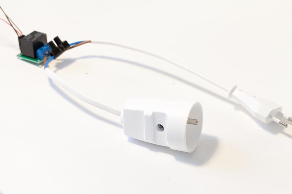
38 2.1 Hardware & Software Requirements Let s first see what we need to build this project. For the Arduino board, I simply used an Arduino Uno R3 board. For the Internet connectivity, I used the Arduino Ethernet shield, which is very convenient to connect your projects to the Internet and to build Internet of Things projects. Then, for the relay module, I used a 5V relay module from Polulu, which nicely integrates a relay on a board, along with all the required components to control the relay from Arduino. This is a picture of the relay module I used: To connect to the lamp to the project, I used a standard pair of power plugs with bare cables at the end, with one female socket (to plug the lamp in) and one male socket (to plug it into the power socket in the wall). This is a picture of the cables I used:
 Arduino Ethernet Shield (https://www.adafruit.")
39 Note that you can perfectly test this project without having anything connected to the relay: you can build the Arduino part first, and then decide which device you want to connect to it later. This a list of the components that are required for this project: Arduino Uno ( Arduino Ethernet Shield ( Relay module ( Female/male jumper wires ( On the software side, you will of course need the usual Arduino IDE. You also need the Teleduino library, which you can download at: To install the library, simply extract the folder in your Arduino /libraries folder (or create this folder if it doesn t exist yet). You will also need to get an API key to use the Teleduino service. To do so, go to this link: You will be taken to this page where you can request your key:
40

41 2.2 Connecting a Relay and a Lamp to Arduino Assembling the hardware for this project is really simple. First, plug the Ethernet shield on top of your Arduino board, and connect the shield to your Internet router via an Ethernet cable. For the relay module, there are three pins you need to connect: VCC, GND and SIG. VCC needs to go the Arduino 5V pin, and GND goes to the Arduino ground pin. Finally, connect the SIG pin to pin number 7 of the Arduino board. This is a picture of the project at this point: We are now going to connect the lamp to the hardware we already assembled. Basically, the idea is to have the main power supply (coming from the power socket in the wall) going to the relay on the COM pin, going out of the relay via the NO pin, and finally back to the lamp. This picture summarizes the connections between the different parts:
42 Note that I didn t use any earth connections for this project, on both the male and the female plugs. Also note that this project is shown for education purposes only. It could be indeed really unsafe to use this project as it is in your home, as using the mains electricity directly is dangerous. If you want to install this project in your home, consider putting all the project in a plastic enclosure so it cannot be touched when in operation. This is a picture of the completely assembled project:
43
44 2.3 Testing the Relay It is now time to test the project. As the most important part of the project is the relay module, this is what we are going to test here. We are simply going to switch the relay on and off continuously every 5 seconds, just to check that the relay is working correctly. At this point, you can already plug a device (like the lamp I used as an example) into the project and connect the switch to an electrical socket, to see that all the connections are correctly made. This is the complete code for this section: // Sketch to test the relay // Relay pin const int relay_pin = 7; void setup() { pinmode(relay_pin,output); } void loop() { } // Activate relay digitalwrite(relay_pin, HIGH); // Wait for 5 seconds delay(5000); // Deactivate relay digitalwrite(relay_pin, LOW); // Wait for 5 seconds delay(5000); Note that all the files are available on the GitHub repository of the book: It is now time to test the sketch. Make sure that the lamp is correctly connected to the project, and that the male plug is plugged into the power socket in the wall. Then, upload the Arduino sketch to the board. You should see that every 5 seconds, the relay is switching, turning the device connected to it on and off.
45 2.4 Controlling Your Project From Anywhere Now that we are sure that the relay is working correctly, we can move on to the core of this chapter: controlling the relay from anywhere you are in the world. You will be able to control it from any web browser, just by knowing your API key that you got before. There is one more thing you need to do before we can have a look into the Arduino sketch of this section. You need to convert the API key you got before to hexadecimal format, so it can be pasted inside the Arduino sketch. Luckily, the Teleduino website has a page to do that: You will be taken to a page where you can paste your API key: You will receive in return some code. Just copy this code somewhere else for now, or keep the web page open: we will need this hexadecimal code quite soon. We are now going to see the most important points of the Arduino sketch of this section. The code itself is given by Teleduino and is really complex, so refer to the code inside the GitHub repository to get the complete code for this project. The sketch starts by including the required libraries for the project: #include <EEPROM.h> #include <Servo.h> #include <Wire.h> #include <Teleduino328.h> #include <SPI.h> #include <Ethernet.h>
46 Then, you need to enter the MAC address of your Arduino Ethernet shield. You can find it below the shield itself. Just enter it in the mac variable: byte mac[] = { 0x90, 0xA2, 0xDA, 0x0E, 0xFE, 0x40 }; Later in the code, you can also paste your API key in hexadecimal format: byte key[] = { 0x64, 0x26, 0xFF, 0xC9, 0x20, 0x4C, 0xF2, 0xCF, 0xAE, 0x42, 0xD4, 0x1A, 0xED, 0x6C, 0xB0, 0xB7 }; Now, we declare the pin on which you can connect a LED to monitor the status of Teleduino. I didn t use this feature for this project, but if you want to do so you can just connect a LED to this pin: byte statusledpin = 8; We also declare an Ethernet client, that we will use to connect to the Teleduino service: EthernetClient Client; Now, in the setup() function of the sketch, we initialize the Ethernet shield using the begin() function. If this function is successful (meaning that the Ethernet shield got an IP address), we reset the Teleduino object: if(!ethernet.begin(mac)) { Teleduino328.setStatusLed(2, false, 10000); Teleduino328.reset(); } In the loop() function of the sketch, the important part is to call the Teleduino instance whenever we are connected to the web: if(client.connected()) The rest of the code is about handling the request by the Teleduino service, and we will not get into the details of this part. Note that all the files are available on the GitHub repository of the book: It s now time to test the project. Make sure that you grabbed the code from the GitHub repository, and that you insert the MAC address of your shield and the API key inside the code. Now, you can upload the code to the Arduino board.
47 Wait for a moment, and then open your favorite web browser. The first thing we have to do is to set the pin number 7 as an output. This can be done by typing the appropriate command in your web browser (make sure to replace yourkey by your own API key): r=definepinmode&pin=7&mode=1 After typing this command, you should get a confirmation inside your web browser. After that, you can type the following command to turn the relay on: r=setdigitaloutput&pin=7&output=1 You should see that the lamp turns on instantly. To switch it off again, simply type: r=setdigitaloutput&pin=7&output=0 Congratulations, you can now control this lamp from anywhere in the world! In case it is not working at this point, first make sure that your Internet connection is up and running. Also, make sure that you correctly enterered your Teleduino API key. Finally, make sure to always use the latest version of the code from the GitHub repository of the book.
48 2.5 How to Go Further Let s summarize what we did in this chapter. We built a project to control a lamp (or any other electrical device in your home) that can be controlled from anywhere. We used the Arduino Ethernet shield to connect the project to the web, and the Teleduino service so you can simply control your project from a web browser. Because the Teleduino service works wherever you are in the world, this lamp can now be controlled from anywhere. There are of course many ways to improve this project. Of course, you can plug more than one relay module to the project, allowing you to control many different electrical devices at once. For example, you can connect many lamps to the project, along with other electrical appliance like water heaters or coffee machines. You can also read data using this project. Using this function of Teleduino, you can read from sensors remotely. For example, you can imagine inserting a current sensor into the project, to be able to follow the energy consumption of your lamp remotely. To get more details on how to do so, I invite you to read the Teleduino API documentation on their website:
49 Chapter 3 A Weather Station in the Cloud In this chapter, you are going to build a weather measurement station that will automatically send data to the cloud. To do so, we will use the powerful Arduino Yun board with the Temboo service. Introduced in 2013 by Arduino, the Arduino Yun is a powerful Arduino board with on board WiFi & that also feature a small Linux machine. It is especially really easy to interface with the web service Temboo, which is what we are going to use in this chapter. We will automatically send data to a Google Docs spreadsheet, which can be accessed from anywhere.
50 3.1 Hardware & software requirements For this project, you will of course need the Arduino Yun board. You will also need a DHT11 (or DHT22) sensor, along with a 4.7K resistor, for humidity measurements. For pressure & temperature measurements, I used a BMP085 sensor on a breakout board. You can also use the newer BMP180 sensor, which works with the same library. For light levels measurements, I used a photocell with a 10K Ohm resistor. Finally, I used a breadboard and some male-male jumper wires. Arduino Yun ( DHT11 sensor + 4.7K resistor ( Photocell ( 10K Ohm resistor ( BMP180 sensor ( Some male/male jumper wires ( Breadboard ( On the software side, you will need the Arduino IDE 1.5.x in the latest version (in Beta when this article was written): You will also need the DHT library: The BMP085 or BMP180 library: And the Adafruit unified sensor library: To install a library, simply put the folder in your /libraries/ folder of you main Arduino folder. This tutorial also assumes that your Arduino Yun is already connected to your WiFi network. If you need help with that, please follow the dedicated tutorial on the Arduino website:
51 You will also need a Google account for the rest of the project. If you don t have one yet, please create one, for example by going on the Google Drive page:

52 3.2 Hardware configuration The hardware connections for this project are actually quite simple. We have to connect the DHT11 sensor, the pressure sensor, and the part responsible for the light level measurement. The following picture summarizes the hardware connection: This image was created with Fritzing ( First, place the DHT11 sensor and the BMP sensor on the breadboard. After that, connect the Arduino Yun +5V pin to the red rail on the breadboard, and the ground pin to the blue rail. Then, connect pin number 1 of the DHT11 sensor (see the schematic) to the red rail on the breadboard, and pin number 4 the blue rail. Also connect pin number 2 to pin number 8 of the Arduino Yun. To complete the connections of the DHT11 sensor, connect the 4.7k Ohm between pin number 1 and 2 of the sensor. For the photocell, first place the cell in series with the 10k Ohm resistor on the breadboard. Then, connect the other end of the photocell to the red rail on the breadboard, and the other end of the resistor to the ground. Finally, connect the common pin to the Arduino Yun analog pin A0. For the BMP085 or BMP180 sensor, connect the VIN pin to the +5V and GND to Ground. Then, connect the SCL pin to Arduino Yun pin number 3, and the SDA pin to Arduino Yun pin number 2.

53 You can see how the assembled project looks like on this picture:
54 3.3 Testing The Sensors Before connecting the project to the cloud, we will test every sensors individually. To do so, we will write a simple test sketch. This is the complete code for this part: // Include required libraries #include "DHT.h" #include <Wire.h> #include <Adafruit_Sensor.h> #include <Adafruit_BMP085_U.h> // Variables int lightlevel; float humidity; float temperature; unsigned long time; // DHT11 sensor pins #define DHTPIN 8 #define DHTTYPE DHT11 // DHT & BMP instances DHT dht(dhtpin, DHTTYPE); Adafruit_BMP085_Unified bmp = Adafruit_BMP085_Unified(10085); void setup(void) { } // Initialize DHT sensor dht.begin(); // Init serial Serial.begin(115200); // Initialise the sensor if(!bmp.begin()) { Serial.print("Ooops, no BMP085 detected Check your wiring or I2C ADDR!"); while(1); } void loop(void) { // Measure the humidity float humidity = dht.readhumidity(); // Measure light level int lightlevel = analogread(a0); // Measure pressure & temperature from BMP sensor sensors_event_t event; bmp.getevent(&event); float pressure = event.pressure; float temperature; bmp.gettemperature(&temperature); float sealevelpressure = SENSORS_PRESSURE_SEALEVELHPA; float altitude; altitude = bmp.pressuretoaltitude(sealevelpressure, event.pressure, temperature); // Print measurements Serial.print("Humidity: "); Serial.println(humidity);
55 Serial.print("Light level: "); Serial.println(lightLevel); Serial.print("Barometric pressure: "); Serial.println(pressure); Serial.print("Temperature: "); Serial.println(temperature); Serial.print("Altitude: "); Serial.println(altitude); Serial.println(""); // Repeat 50 ms delay(50); } Let s now see the details of the code. The first step in the code is to import the correct libraries: #include "DHT.h" #include <Wire.h> #include <Adafruit_Sensor.h> #include <Adafruit_BMP085_U.h> We need to define the pin & type of the DHT sensor: #define DHTPIN 8 #define DHTTYPE DHT11 And create the instances for the DHT sensor & BMP sensor: DHT dht(dhtpin, DHTTYPE); Adafruit_BMP085_Unified bmp = Adafruit_BMP085_Unified(10085); In the setup() function, we can initialize the BMP sensor: bmp.begin() In the loop() part of the sketch, we make the different measurements: // Measure the humidity float humidity = dht.readhumidity(); // Measure light level int lightlevel = analogread(a0); // Measure pressure & temperature from BMP sensor sensors_event_t event; bmp.getevent(&event); float pressure = event.pressure; These measurements will then be printed on the Serial monitor. Note that all the code is available inside the GitHub repository of the book: You can now upload the sketch to the board & open the Serial monitor (making sure the Serial speed matches the one you defined in the code). This is what you should see:

56 If that works, it means all your hardware connections are correct, and you can move to the next part of the project. In case it is not working at this point, there are several things you can check. First, make sure you that correctly downloaded & installed all the Arduino libraries that are required for this project. Also make sure that you correctly followed the instructions to assemble the project.
57 3.4 Setting up your Temboo account Before you can upload data to Google Docs, you need to have a Temboo account. Go over to the Temboo website and enter your to start the account creation process: You will also be prompted to enter an account name: After that step, you can go to the Account tab, and then to Applications. You will find your first application name (should be myfirstapp by default) and your API key. Please keep your account name, application name and API key at hand, you will need them soon.
58 3.5 Logging Data to Google Docs It is now time to build the software part of our project. First, we will do some configuration in Google Docs. Create a new spreadsheet in Google Docs, and give it a name (I named mine Yun ). Then, enter the title of each columns in the first row, like the picture below: Now, we are going to build the Arduino sketch. This is the complete code for this part: #include <Bridge.h> #include <Temboo.h> #include <Process.h> #include <Wire.h> #include <Adafruit_Sensor.h> #include <Adafruit_BMP085_U.h> // Contains Temboo account information #include "TembooAccount.h" // Variables int lightlevel; float humidity; float temperature; unsigned long time; // Process to get the measurement time Process date; // Your Google Docs data const String GOOGLE_USERNAME = "your address"; const String GOOGLE_PASSWORD = "yourpassword"; const String SPREADSHEET_TITLE = "Yun"; // Include required libraries #include "DHT.h" // DHT11 sensor pins #define DHTPIN 8 #define DHTTYPE DHT11 // DHT & BMP instances DHT dht(dhtpin, DHTTYPE); Adafruit_BMP085_Unified bmp = Adafruit_BMP085_Unified(10085); // Debug mode? boolean debug_mode = false; void setup() { // Start Serial if (debug_mode == true){ Serial.begin(115200); delay(4000); while(!serial); } // Initialize DHT sensor dht.begin();
59 } // Start bridge Bridge.begin(); // Start date process time = millis(); if (!date.running()) { date.begin("date"); date.addparameter("+%d-%t"); date.run(); } if (debug_mode == true){ Serial.println("Setup complete. Waiting for sensor input \n"); } // Initialise the sensor if(!bmp.begin()) { while(1); } void loop() { } // Measure the humidity & temperature humidity = dht.readhumidity(); // Measure light level int lightlevel = analogread(a0); // Measure pressure & temperature from BMP sensor sensors_event_t event; bmp.getevent(&event); float pressure = event.pressure; bmp.gettemperature(&temperature); float sealevelpressure = SENSORS_PRESSURE_SEALEVELHPA; float altitude; altitude = bmp.pressuretoaltitude(sealevelpressure, event.pressure, temperature); if (debug_mode == true){ Serial.println("\nCalling the AppendRow Choreo "); } // Append data to Google Docs sheet runappendrow(humidity, lightlevel, pressure, temperature, altitude); // Repeat every 10 minutes delay(600000); // Function to add data to Google Docs void runappendrow(float humidity, int lightlevel, float pressure, float temperature, float altitude) { TembooChoreo AppendRowChoreo; // Invoke the Temboo client AppendRowChoreo.begin(); // Set Temboo account credentials AppendRowChoreo.setAccountName(TEMBOO_ACCOUNT); AppendRowChoreo.setAppKeyName(TEMBOO_APP_KEY_NAME); AppendRowChoreo.setAppKey(TEMBOO_APP_KEY); // Identify the Choreo to run AppendRowChoreo.setChoreo("/Library/Google/Spreadsheets/AppendRow"); // your Google username (usually your address) AppendRowChoreo.addInput("Username", GOOGLE_USERNAME); // your Google account password AppendRowChoreo.addInput("Password", GOOGLE_PASSWORD);
60 } // the title of the spreadsheet you want to append to AppendRowChoreo.addInput("SpreadsheetTitle", SPREADSHEET_TITLE); // Restart the date process: if (!date.running()) { date.begin("date"); date.addparameter("+%d-%t"); date.run(); } // Get date String timestring = date.readstring(); // Format data String data = ""; data = data + timestring + "," + String(humidity) + "," + String(lightLevel) + "," + String(pressure) + "," + String(temperature) + "," + String(altitude); // Set Choreo inputs AppendRowChoreo.addInput("RowData", data); // Run the Choreo unsigned int returncode = AppendRowChoreo.run(); // A return code of zero means everything worked if (returncode == 0) { if (debug_mode == true){ Serial.println("Completed execution of the AppendRow Choreo.\n"); } } else { // A non-zero return code means there was an error // Read and print the error message while (AppendRowChoreo.available()) { char c = AppendRowChoreo.read(); if (debug_mode == true){ Serial.print(c); } } if (debug_mode == true){ Serial.println(); } } AppendRowChoreo.close(); Let s now see the details of the code. You need to import all the libraries for the Arduino Yun web & bridge functionalities: #include <Bridge.h> #include <Temboo.h> #include <Process.h> #include <Wire.h> #include <Adafruit_Sensor.h> #include <Adafruit_BMP085_U.h> I also placed all my Temboo account information in a separate file called Temboo.h. Please make sure that you update your personal account information in this file. This is the content of this file: #define TEMBOO_ACCOUNT "tembooaccountname" // Your Temboo account name #define TEMBOO_APP_KEY_NAME "myfirstapp" // Your Temboo app key name #define TEMBOO_APP_KEY "tembooaccountkey" // Your Temboo app key We then have to include it inside the sketch: #include "TembooAccount.h"
61 You also need to set your own informations about your Google account: const String GOOGLE_USERNAME = "your address"; const String GOOGLE_PASSWORD = "yourpassword"; const String SPREADSHEET_TITLE = "Yun"; Note that if you are using Google s two-step verification, you will need to get an application-specific password for this step. You can get one here: In the setup() function, we start the Bridge between the Arduino part & the Linux machine with: Bridge.begin(); We also start a date process, to automatically send the measurements date to Google Docs: time = millis(); if (!date.running()) { date.begin("date"); date.addparameter("+%d-%t"); date.run(); } In the loop() function, the most important line is: runappendrow(humidity, lightlevel, pressure, temperature, altitude); This function calls the function to automatically send the data to the Google Docs spreadsheet. I won t get into the details of this function, but of course you will find all the code in the GitHub repository of this project. The loop() of the Arduino sketch is repeated every 10 minutes with a delay() function, as these variables are usually changing slowly over time. Note that all the code is available inside the GitHub repository of the book: Finally, you are ready to test the project. Make sure you modified the files with your own data, upload the code to the Arduino Yun board. After that, open the Google Docs spreadsheet in your browser again, and wait a moment. After a while, the first measurement should appear inside the spreadsheet:
62 I also used the built-in plotting functions of Google Docs to plot my data as it comes in. For example, I used the simple Line chart type to plot the light level. This is the result over some hours in the morning, showing that the light level is slowly rising over time: And over the same period of time, I plotted the evolution of the temperature & humidity: The really nice thing about this project is that it is updated automatically as data comes in. It can also be accessed from anywhere: you just need your Google user name & password! In case it is not working at this point, there are several things you can check. First, make sure that you correctly configured your Arduino Yun board, and that it can access the Internet. Also make sure that you correctly set up your Google Docs spreadsheet. Finally, make sure that you entered your Temboo & Google account credentials inside the Arduino
63 files after your downloaded the files from the GitHub repository of the book.
64 3.6 How to Go Further Let s summarize what you learned in this chapter. You just learned how to send measurements from your Arduino Yun board to Google Docs, so this data can be accessed from anywhere. We also saw how to plot this data, so you can monitor measurements live from your web browser. You can of course improve this project in many ways. The first one is to add more sensors to the project, for example a wind speed sensor or a smoke sensor. You can of course use many Arduino Yun boards, for example in different parts of your home.
65 Chapter 4 Wireless Security Camera Ever saw these wireless security cameras that you can buy off the shelf? These are devices that you can just put somewhere in your home or outside and connect them to your WiFi network. After that, they automatically take pictures if some motion is detected, for example. However, they are usually using the interface given by the manufacturer, which means you are quite limited with what you can do with your camera. In this chapter, we are going to build our own DIY version of such device. The project is based on the Arduino Yun, to which we are going to connect a standard USB webcam and a PIR motion sensor to create a nice Internet of Things application. The application will be a modern version of a standard task that you expect from a security camera: taking pictures when some motion is detected. The project will store pictures taken by the USB camera on an SD card inserted into the Yun, but that is not all. Because we are in a book about the Internet of Things, we also want these pictures to be automatically uploaded on a secure location. And that is exactly what we are going to do by uploading the pictures to Dropbox at the same time.
66 4.1 Hardware & Software Requirements The first step is to make sure you have the right hardware components. First off, you will need an Arduino Yun, and a PIR motion sensor. For the USB camera, you can choose any webcam that is compatible with the UVC protocol. Most of the recent webcams are compatible. I chose a Logitech C270 that can take pictures up to 720p resolution. You can find a list of compatible cameras here: You will also need a microsd card to store the pictures locally on your Arduino Yun, and some female/male jumper wires to connect the PIR motion sensor. This a list of the components that are required for this project: Arduino Yun ( USB webcam ( PIR motion sensor ( MicroSD card ( Some female/male jumper wires ( Before we can build exciting applications with our hardware, we need to setup some accounts on the web services we are going to use. The first one is Temboo, where you will need to create an account (if you didn t create one yet after following the previous chapter). Temboo will basically make the interface between the Arduino Yun and Dropbox. Just go over to: You will be prompted to create an account, and then your first app. Write down the name of your account, the name of the app and your app API key, you will need them later. There is also one more thing you need from the Temboo website: the Temboo Python SDK. We will use it later to upload pictures to Dropbox from the Arduino Yun. You can get it at: Once downloaded, simply extract the temboo folder at the root of the microsd card. Then, you need a Dropbox account. Go over to the Dropbox website to do so:


67 Once the account is created, you need to create an App so the Yun can upload pictures to your Dropbox folder. To create an app, you need to go to the developers section of Dropbox: Then, click on Create app, and choose which type of app you want to create (Dropbox API app for our project): Then, select Files and datastores : After that, you can give a name to your app and create it. Also specify that your app should only have access the files in its own folder. What you need to get now is all the keys relative to your Dropbox app, so you can enter them later in the software part of the chapter. You will need the App Key and App Secret at this point, which are displayed on the same page as your app. The next set of data we need to get is the Token Key & Token Secret key. To get them, the first step is to go to the InitialiseOAuth Choreo on the Temboo website: Here, you will need to enter the App Key and App Secret. That will generate some additional information, like a callback ID, and a temporary token secret. You ll also be asked to visit a link to Dropbox to confirm the authentication. Finally, go to the FinalizeOAuth page to finish the process. You will be asked to enter your App Key, App Secret, callback ID and temporary token secret:
68 After that step, you will be given your final Token Key and Token Secret. Write them down as well, you will need them later.


69 4.2 Connecting a USB Camera to the Yun The first step is to insert the microsd card in the Arduino Yun board: Then, connect the camera to the USB port of the Yun:

70 Finally, connect the motion sensor to the Yun. Simply connect the VCC pin to the Yun 5V pin, GND to GND, and the SIG pin to the Yun pin number 8: Finally, just connect the project to your computer via the microusb port, and you are good to go.
Adafruit CC3000 WiFi and Xively
 Adafruit CC3000 WiFi and Xively Created by Marc-Olivier Schwartz Last updated on 2018-08-22 03:37:52 PM UTC Guide Contents Guide Contents Introduction Setting up your Xively account Connections DHT11 sensor
Home Automation With Arduino
 Home Automation With Arduino Automate Your Home Using Open-Source Hardware Marco Schwartz, PhD Contents Legal Acknowledgments About the author About the companion website Preface to the First Edition Preface
Make a Simple Weather Station Using Arduino
 Make a Simple Weather Station Using Arduino In this article, you will learn how to build your own weather station using the Arduino platform. This tutorial is based on the work from Steve Spence from Arduinotronics,
Bosch BMP085 Breakout Board
 Bosch BMP085 Breakout Board Created by lady ada Last updated on 2014-11-07 03:00:29 PM EST Guide Contents Guide Contents Overview Specifications Wiring the BMP085 Using the BMP085 (API v2) Using the BMP085
WIFI CC3000 Module Breakout
 WIFI CC3000 Module Breakout This is a breakout board for the CC3000 WiFi Module from TI (Texas Instruments). It is a self-contained wireless network processor that makes internet connectivity into your
Adafruit CAP1188 Breakout
 Adafruit CAP1188 Breakout Created by lady ada Last updated on 2014-05-14 12:00:10 PM EDT Guide Contents Guide Contents Overview Pinouts Power pins I2C interface pins SPI inteface pins Other interfacing
Create your own wireless motion sensor with
 Create your own wireless motion sensor with Arduino If you have a friend that has an alarm system in his or her home, I am sure you ve all seen these white motion sensors that are usually fixed above doors
Arduino Package Tracker
 Arduino Package Tracker Created by Vaughn Shinall Last updated on 2016-02-24 04:25:10 PM EST Guide Contents Guide Contents Overview Parts Credentials Generate Your Sketch Parse Your Output Add an Alert
#include "DHT.h" DHT dht(dhtpin, DHTTYPE); // Date and time functions using a DS1307 RTC connected via I2C and Wire lib
; // Date and time functions using a DS1307 RTC connected via I2C and Wire lib") #include "DHT.h" #define DHTPIN 2 // what pin we're connected to // Uncomment whatever type you're using! #define DHTTYPE DHT11 // DHT 11 //#define DHTTYPE DHT22 // DHT 22 (AM2302) //#define DHTTYPE DHT21
#include "DHT.h" #define DHTPIN 2 // what pin we're connected to // Uncomment whatever type you're using! #define DHTTYPE DHT11 // DHT 11 //#define DHTTYPE DHT22 // DHT 22 (AM2302) //#define DHTTYPE DHT21
Inclusions required for the DMD
 Sketch for Home Alert The sketch is not large in terms of the line count, but it almost exhausts the Uno s available flash memory thanks to all the included libraries. There is lots of room for memory
LIS3DH Hookup Guide. Introduction. SparkFun Triple Axis Accelerometer Breakout - LIS3DH SEN Required Materials
 Page 1 of 15 LIS3DH Hookup Guide Introduction The LIS3DH is a triple axis accelerometer you can use to add translation detection to your project. It would be classified as a 3DoF, or 3 Degrees of Freedom.
Yun Shield Quick Start Guide VERSION: 1.0. Yun Shield Quick Start Guide 1 / 14.
 Yun Shield Quick Start Guide VERSION: 1.0 Version Description Date 1.0 Release 2014-Jul-08 1.1 Change Password to dragino 2014-Aug-02 Yun Shield Quick Start Guide 1 / 14 Index: 1 Introduction... 3 1.1
free ebooks ==>
 Home Automation With the ESP8266 Build Home Automation Systems Using the Powerful and Cheap ESP8266 WiFi Chip Marco Schwartz, PhD Contents Legal About the author About the companion website Chapter 1 free
Adafruit 1-Wire Thermocouple Amplifier - MAX31850K
 Adafruit 1-Wire Thermocouple Amplifier - MAX31850K Created by lady ada Last updated on 2018-08-22 03:40:09 PM UTC Guide Contents Guide Contents Overview Pinouts Power Pins Address Pins Data Pin Themocouple
Adafruit BMP280 Barometric Pressure + Temperature Sensor Breakout
 Adafruit BMP280 Barometric Pressure + Temperature Sensor Breakout Created by lady ada Last updated on 2017-12-09 06:21:37 PM UTC Guide Contents Guide Contents Overview Pinouts Power Pins: SPI Logic pins:
Documentation for Wifi-Enabled Data Logging - System Control By: Jesse Jenkins
 Documentation for Wifi-Enabled Data Logging - System Control By: Jesse Jenkins Code for this project is found on Github: https://github.com/hedronuser/metabolizer For getting started with Blynk, check
ipot Phase 1 1
 ipot Phase 1 Contents Introduction... 3 Step 1: Connect the Soil Humidity Hygrometer Moisture sensor... 5 Step 2: Connect DHT22 Humidity and Temperature sensor... 8 Step 3: Connecting OLED U8glib screen...
ROBOTLINKING THE POWER SUPPLY LEARNING KIT TUTORIAL
 ROBOTLINKING THE POWER SUPPLY LEARNING KIT TUTORIAL 1 Preface About RobotLinking RobotLinking is a technology company focused on 3D Printer, Raspberry Pi and Arduino open source community development.
Adafruit BME280 Humidity + Barometric Pressure + Temperature Sensor Breakout
 Adafruit BME280 Humidity + Barometric Pressure + Temperature Sensor Breakout Created by lady ada Last updated on 2018-08-22 03:49:22 PM UTC Guide Contents Guide Contents Overview Pinouts Power Pins: SPI
Adafruit BME680. Created by lady ada. Last updated on :10:23 AM UTC
 Adafruit BME680 Created by lady ada Last updated on 2018-01-22 05:10:23 AM UTC Guide Contents Guide Contents Overview Pinouts Power Pins: SPI Logic pins: I2C Logic pins: Assembly Prepare the header strip:
Adafruit 1-Wire GPIO Breakout - DS2413
 Adafruit 1-Wire GPIO Breakout - DS2413 Created by Bill Earl Last updated on 2018-08-22 03:40:00 PM UTC Guide Contents Guide Contents Overview Assembly & Wiring Headers Position the Header And Solder! Wiring
Adafruit 1-Wire Thermocouple Amplifier - MAX31850K
 Adafruit 1-Wire Thermocouple Amplifier - MAX31850K Created by lady ada Last updated on 2015-04-09 03:45:15 PM EDT Guide Contents Guide Contents Overview Pinouts Power Pins Address Pins Data Pin Themocouple
RedBoard Hookup Guide
 Page 1 of 11 RedBoard Hookup Guide CONTRIBUTORS: JIMB0 Introduction The Redboard is an Arduino-compatible development platform that enables quick-and-easy project prototyping. It can interact with real-world
Adafruit Ethernet FeatherWing
 Adafruit Ethernet FeatherWing Created by lady ada Last updated on 2017-07-14 05:32:28 AM UTC Guide Contents Guide Contents Overview Pinouts Power Pins SPI Data Pins Other Breakouts Assembly Prepare the
Adafruit BME280 Humidity + Barometric Pressure + Temperature Sensor Breakout
 Adafruit BME280 Humidity + Barometric Pressure + Temperature Sensor Breakout Created by lady ada Last updated on 2017-01-11 09:01:04 PM UTC Guide Contents Guide Contents Overview Pinouts Power Pins: SPI
TA0013 ARDUINO RFID UNO STARTER KIT
 TA0013 ARDUINO RFID UNO STARTER KIT Overview TA0013 This Arduino Uno ultimate project kit includes comprehensive range of components to get you started in building and experimenting with Arduino projects.
Monitor your home remotely using the Arduino
 Monitor your home remotely using the Arduino WiFi Shield How to monitor some data in your home using precisely this Arduino WiFi shield. Along with the Arduino Uno board, the final system will form an
Arduino 101 AN INTRODUCTION TO ARDUINO BY WOMEN IN ENGINEERING FT T I NA A ND AW E S O ME ME NTO R S
 Arduino 101 AN INTRODUCTION TO ARDUINO BY WOMEN IN ENGINEERING FT T I NA A ND AW E S O ME ME NTO R S Overview Motivation Circuit Design and Arduino Architecture Projects Blink the LED Switch Night Lamp
Guide to practical classes in IoT design and integration
 Guide to practical classes in IoT design and integration for students in Computer Science Introduction This experimental teaching module is first of the kind taught in our department. The study is based
Hardware Overview. Onboard Sensors. Pressure, Humidity, and Temperature. Air Quality and Temperature
 Hardware Overview The ESP32 Environment Sensor Shield incorporates three sensors capable of measuring five different environmental variables. It also provides connections for several other sensors that
Note. The above image and many others are courtesy of - this is a wonderful resource for designing circuits.
 Robotics and Electronics Unit 2. Arduino Objectives. Students will understand the basic characteristics of an Arduino Uno microcontroller. understand the basic structure of an Arduino program. know how
IME-100 Interdisciplinary Design and Manufacturing
 IME-100 Interdisciplinary Design and Manufacturing Introduction Arduino and Programming Topics: 1. Introduction to Microprocessors/Microcontrollers 2. Introduction to Arduino 3. Arduino Programming Basics
IME-100 ECE. Lab 3. Electrical and Computer Engineering Department Kettering University. G. Tewolde, IME100-ECE,
 IME-100 ECE Lab 3 Electrical and Computer Engineering Department Kettering University 3-1 1. Laboratory Computers Getting Started i. Log-in with User Name: Kettering Student (no password required) ii.
Adafruit DS3231 Precision RTC Breakout
 Adafruit DS3231 Precision RTC Breakout Created by lady ada Last updated on 2016-02-05 04:43:25 PM EST Guide Contents Guide Contents Overview Pinouts Power Pins: I2C Logic pins: Other Pins: Assembly Prepare
Dual rocket altimeter using the ATmega 328 microcontroller. The AltiDuo
 Dual rocket altimeter using the ATmega 328 microcontroller The AltiDuo Version date Author Comments 1.0 29/12/2012 Boris du Reau Initial Version Boris.dureau@neuf.fr 1.1 17/02/2013 Boris du Reau Updated
Adafruit HMC5883L Breakout - Triple-Axis Magnetometer Compass Sensor
 Adafruit HMC5883L Breakout - Triple-Axis Magnetometer Compass Sensor Created by lady ada Last updated on 2016-09-14 07:05:05 PM UTC Guide Contents Guide Contents Overview Pinouts Assembly Prepare the header
MPR121 Hookup Guide. MPR121 Overview. Materials
 Page 1 of 24 MPR121 Hookup Guide CONTRIBUTORS: TONI_K MPR121 Overview If you are interested in adding the magic of touch to control your electronics project, a capacitive touch sensor might be the way
F_Thingspeak INNEN DG Temperatur- und Druckmessung V1_00. F_Thingspeak INNEN DG Temperatur- und Druckmessung V1_00.ino
 F_Thingspeak INNEN DG Temperatur- und Druckmessung V1_00 F_Thingspeak INNEN DG Temperatur- und Druckmessung V1_00.ino 1 /* 2 TEMPERATURMESSUNG INNEN über Thingspeak 3 V1.00 23.06.2015 Übernahme des Programms
Sanguino TSB. Introduction: Features:
 Sanguino TSB Introduction: Atmega644 is being used as CNC machine driver for a while. In 2012, Kristian Sloth Lauszus from Denmark developed a hardware add-on of Atmega644 for the popular Arduino IDE and
Arduino Android Blueprints
 Arduino Android Blueprints Get the best out of Arduino by interfacing it with Android to create engaging interactive projects Marco Schwartz Stefan Buttigieg BIRMINGHAM - MUMBAI Arduino Android Blueprints
SX1509 I/O Expander Breakout Hookup Guide
 Page 1 of 16 SX1509 I/O Expander Breakout Hookup Guide Introduction Is your Arduino running low on GPIO? Looking to control the brightness of 16 LEDs individually? Maybe blink or breathe a few autonomously?
AT42QT1010 Capacitive Touch Breakout Hookup Guide
 Page 1 of 7 AT42QT1010 Capacitive Touch Breakout Hookup Guide Introduction If you need to add user input without using a button, then a capacitive touch interface might be the answer. The AT42QT1010 Capacitive
This tutorial will show you how to take temperature readings using the Freetronics temperature sensor and an Arduino Uno.
 This tutorial will show you how to take temperature readings using the Freetronics temperature sensor and an Arduino Uno. Note that there are two different module types: the temperature sensor module and
Alessandra de Vitis. Arduino
 Alessandra de Vitis Arduino Arduino types Alessandra de Vitis 2 Interfacing Interfacing represents the link between devices that operate with different physical quantities. Interface board or simply or
Arduino Platform Part I
 Arduino Platform Part I Justin Mclean Class Software Email: justin@classsoftware.com Twitter: @justinmclean Blog: http://blog.classsoftware.com Who am I? Director of Class Software for almost 15 years
The DTMF generator comprises 3 main components.
 Make a DTMF generator with an Arduino board This article is for absolute beginners, and describes the design and construction of a DTMF generator. DTMF generators are often used to signal with equipment
Introduction to Programming. Writing an Arduino Program
 Introduction to Programming Writing an Arduino Program What is an Arduino? It s an open-source electronics prototyping platform. Say, what!? Let s Define It Word By Word Open-source: Resources that can
ARDUINO YÚN MINI Code: A000108
 ARDUINO YÚN MINI Code: A000108 The Arduino Yún Mini is a compact version of the Arduino YUN OVERVIEW: Arduino Yún Mini is a breadboard PCB developed with ATmega 32u4 MCU and QCA MIPS 24K SoC CPU operating
ESPino - Specifications
 ESPino - Specifications Summary Microcontroller ESP8266 (32-bit RISC) WiFi 802.11 (station, access point, P2P) Operating Voltage 3.3V Input Voltage 4.4-15V Digital I/O Pins 9 Analog Input Pins 1 (10-bit
Internal Report: Heterogeneous IoT Network: TRACK-IoT Plateform. System Architecture. Controller. Proposed by: Hakima Chaouchi
 Internal Report: Heterogeneous IoT Network: TRACK-IoT Plateform Proposed by: Hakima Chaouchi Team: Hakima Chaouchi; Kevin Raymond, Oscar Botero, Abderahim Ait Wakrim, Thomas Bourgeau. The TrackIot platform
AT42QT101X Capacitive Touch Breakout Hookup Guide
 Page 1 of 10 AT42QT101X Capacitive Touch Breakout Hookup Guide Introduction If you need to add user input without using a button, then a capacitive touch interface might be the answer. The AT42QT1010 and
ADXL343 Breakout Learning Guide
 ADXL343 Breakout Learning Guide Created by Kevin Townsend Last updated on 2019-02-19 07:38:05 PM UTC Guide Contents Guide Contents Overview Technical Characteristics Pinout Power Pins Digital Pins Assembly
ArduCAM-M-2MP ESP8266 Evaluation Kit User Guide. Rev 1.1, March 2017
 ArduCAM-M-2MP ESP8266 Evaluation Kit User Guide Rev 1.1, March 2017 Table of Contents 1 Introduction... 2 2 Kit Content... 2 3 Features... 2 4 Pin Definition... 3 5 Wiring Diagram... 4 6 Getting Started
keyestudio Keyestudio MEGA 2560 R3 Board
 Keyestudio MEGA 2560 R3 Board Introduction: Keyestudio Mega 2560 R3 is a microcontroller board based on the ATMEGA2560-16AU, fully compatible with ARDUINO MEGA 2560 REV3. It has 54 digital input/output
Adafruit HTU21D-F Temperature & Humidity Sensor
 Adafruit HTU21D-F Temperature & Humidity Sensor Created by lady ada Last updated on 2014-07-26 01:30:08 PM EDT Guide Contents Guide Contents Overview Pinouts Power Pins: I2C Logic pins: Assembly Prepare
Cloud Hoppers Weather Station using Arduino Uno Board and Ethernet Shield
 Maplin weather station part numbers: Anemometer 2.49 part number :- N25FR Wind direction sensor 9.99:-N96FY You can build this onto a little strip board for easy connection :) Ardunio with Ethernet Shield
2.2" TFT Display. Created by lady ada. Last updated on :19:15 PM UTC
 2.2" TFT Display Created by lady ada Last updated on 2017-12-22 11:19:15 PM UTC Guide Contents Guide Contents Overview Pinouts Assembly Arduino Wiring Arduino UNO or Compatible Wiring Wiring for Other
Adafruit INA219 Current Sensor Breakout
 Adafruit INA219 Current Sensor Breakout Created by lady ada Last updated on 2018-01-17 05:25:30 PM UTC Guide Contents Guide Contents Overview Why the High Side? How does it work? Assembly Addressing the
FUNCTIONAL DESCRIPTION
 All things connected Snaptekk www.snaptekk.com Connecting the DHT22 Sensor VCC: to VCC on module DIG: to DIG on module NC: No connection GND: to GND on module FUNCTIONAL DESCRIPTION The Temperature and
Remote Control with the Huzzah + Adafruit.io
 Remote Control with the Huzzah + Adafruit.io Created by Richard Albritton Last updated on 2017-07-30 03:11:01 PM UTC Guide Contents Guide Contents Overview Adafruit IO Setup Creating the Buttons Feed Adding
Adafruit VL53L0X Time of Flight Micro-LIDAR Distance Sensor Breakout
 Adafruit VL53L0X Time of Flight Micro-LIDAR Distance Sensor Breakout Created by lady ada Last updated on 2016-12-05 06:40:45 PM UTC Guide Contents Guide Contents Overview Sensing Capablities Pinouts Power
ITG-3200 Hookup Guide
 Page 1 of 9 ITG-300 Hookup Guide Introduction This is a breakout board for InvenSense s ITG-300, a groundbreaking triple-axis, digital output gyroscope. The ITG-300 features three 16-bit analog-to-digital
StenBOT Robot Kit. Stensat Group LLC, Copyright 2018
 StenBOT Robot Kit 1 Stensat Group LLC, Copyright 2018 Legal Stuff Stensat Group LLC assumes no responsibility and/or liability for the use of the kit and documentation. There is a 90 day warranty for the
ISL RGB Sensor Tutorial By: Sabrina Jones
 ISL 25129 RGB Sensor Tutorial By: Sabrina Jones Overview The ISL29125 RGB sensor is a breakout board made to record the light intensity of the general red, green, and blue spectrums of visible light, that
This is the Arduino Uno: This is the Arduino motor shield: Digital pins (0-13) Ground Rail
 Ground Rail") Reacting to Sensors In this tutorial we will be going over how to program the Arduino to react to sensors. By the end of this workshop you will have an understanding of how to use sensors with the Arduino
Reacting to Sensors In this tutorial we will be going over how to program the Arduino to react to sensors. By the end of this workshop you will have an understanding of how to use sensors with the Arduino
Grove - 3 Axis Digital Accelerometer±16g Ultra-low Power (BMA400)
") Grove - 3 Axis Digital Accelerometer±16g Ultra-low Power (BMA400) The Grove - 3-Axis Digital Accelerometer ±16g Ultra-low Power (BMA400) sensor is a 12 bit, digital, triaxial acceleration sensor with smart
Grove - 3 Axis Digital Accelerometer±16g Ultra-low Power (BMA400) The Grove - 3-Axis Digital Accelerometer ±16g Ultra-low Power (BMA400) sensor is a 12 bit, digital, triaxial acceleration sensor with smart
TSL2561 Luminosity Sensor
 TSL2561 Luminosity Sensor Created by lady ada Last updated on 2015-06-12 12:10:28 PM EDT Guide Contents Guide Contents Overview Wiring the TSL2561 Sensor Using the TSL2561 Sensor Downloads Buy a TSL2561
Adafruit INA219 Current Sensor Breakout
 Adafruit INA219 Current Sensor Breakout Created by Ladyada Last updated on 2013-09-12 10:15:19 AM EDT Guide Contents Guide Contents Overview Why the High Side? How does it work? Assembly Addressing the
Arduino: LCD Diagrams & Code Brown County Library
 Arduino: LCD Diagrams & Code Project 01: Hello, World! Components needed: Arduino Uno board breadboard 16 jumper wires 16x2 LCD screen 10k potentiometer /* LCD 01 : Hello World! Source: Code adapted from
Copyright. Getting Started with Arduino Wiring for Windows 10 IoT Core Agus Kurniawan 1st Edition, Copyright 2016 Agus Kurniawan
 Copyright Getting Started with Arduino Wiring for Windows 10 IoT Core Agus Kurniawan 1st Edition, 2016 Copyright 2016 Agus Kurniawan ** Windows 10 IoT Core, Visual Studio and Logo are trademark and copyright
Adafruit SHT31-D Temperature & Humidity Sensor Breakout
 Adafruit SHT31-D Temperature & Humidity Sensor Breakout Created by lady ada Last updated on 2016-09-16 07:45:55 PM UTC Guide Contents Guide Contents Overview Pinouts Power Pins: I2C Logic pins: Other Pins:
For reference purposes, you can still find all documents (past and current):
:") Introduction The MyDoorOpener project has attracted a surprisingly high number of enthusiasts over the years. This is our third simplified assembly process document, which is always getting simpler and
Introduction The MyDoorOpener project has attracted a surprisingly high number of enthusiasts over the years. This is our third simplified assembly process document, which is always getting simpler and
Introduction to Arduino (programming, wiring, and more!)
") Introduction to Arduino (programming, wiring, and more!) James Flaten, MN Space Grant Consortium with Ben Geadelmann, Austin Langford, et al. University of MN Twin Cities Aerospace Engineering and Mechanics
Introduction to Arduino (programming, wiring, and more!) James Flaten, MN Space Grant Consortium with Ben Geadelmann, Austin Langford, et al. University of MN Twin Cities Aerospace Engineering and Mechanics
Adafruit USB Power Gauge Mini-Kit
 Adafruit USB Power Gauge Mini-Kit Created by Bill Earl Last updated on 2017-07-14 11:55:04 PM UTC Guide Contents Guide Contents Overview Assembly Basic Assembly Solder the female connector. Solder the
Laboratory 1 Introduction to the Arduino boards
 Laboratory 1 Introduction to the Arduino boards The set of Arduino development tools include µc (microcontroller) boards, accessories (peripheral modules, components etc.) and open source software tools
Make your own secret locking mechanism to keep unwanted guests out of your space!
 KNOCK LOCK Make your own secret locking mechanism to keep unwanted guests out of your space! Discover : input with a piezo, writing your own functions Time : 1 hour Level : Builds on projects : 1,,3,4,5
IOX-16 User s Manual. Version 1.00 April Overview
 UM Unified Microsystems IOX-16 User s Manual Version 1.00 April 2013 Overview The IOX-16 Arduino compatible shield is an easy way to add 16 additional digital Input/Output (I/O) lines to your Arduino system.
Metro Minimalist Clock
 Metro Minimalist Clock Created by John Park Last updated on 2018-08-22 04:01:22 PM UTC Guide Contents Guide Contents Overview For this build you'll need: Clock Circuit Code the Clock Display the Clock
ZX Distance and Gesture Sensor SMD Hookup Guide
 Page 1 of 16 ZX Distance and Gesture Sensor SMD Hookup Guide Introduction The ZX Distance and Gesture Sensor is a collaboration product with XYZ Interactive. The innovative people at XYZ Interactive have
Gravity: I2C ADS Bit ADC Module(Arduino & Raspberry Pi Compatible) SKU: DFR0553
 SKU: DFR0553") Gravity: I2C ADS1115 16-Bit ADC Module(Arduino & Raspberry Pi Compatible) SKU: DFR0553 DFRobot I2C ADS1115 16-bit ADC module can accurately collect and convert analog signals. Through this ADC module,
Gravity: I2C ADS1115 16-Bit ADC Module(Arduino & Raspberry Pi Compatible) SKU: DFR0553 DFRobot I2C ADS1115 16-bit ADC module can accurately collect and convert analog signals. Through this ADC module,
Arduino Uno. Power & Interface. Arduino Part 1. Introductory Medical Device Prototyping. Digital I/O Pins. Reset Button. USB Interface.
 Introductory Medical Device Prototyping Arduino Part 1, http://saliterman.umn.edu/ Department of Biomedical Engineering, University of Minnesota Arduino Uno Power & Interface Reset Button USB Interface
How to Use an Arduino
 How to Use an Arduino By Vivian Law Introduction The first microcontroller, TMS-1802-NC, was built in 1971 by Texas Instruments. It owed its existence to the innovation and versatility of silicon and the
ArduCAM-M-2MP ESP8266 Nano V2 Evaluation Kit User Guide
 ArduCAM-M-2MP ESP8266 Nano V2 Evaluation Kit User Guide Rev 2.0, Nov 2017 1 Table of Contents 1. Introduction... 3 2. Kit Contents... 3 3. Features... 3 4. Wiring Diagram... 4 5. Getting Started ESP8266
Stand-alone programming AVRs using CircuitPython
 Stand-alone programming AVRs using CircuitPython Created by lady ada Last updated on 2018-01-25 11:53:17 PM UTC Guide Contents Guide Contents Overview Supported Chips Wiring Power Pins Data Pins Wiring
AndyMark Arduino Tutorial
 AndyMark Arduino Tutorial Tank Drive June 2014 Required: Required Software List: - Kit Arduino IDE - Robot Power Cable Kit (am-0975) RobotOpen Arduino Shield Software - Battery Base Package (am-0477) RobotOpen
Prototyping & Engineering Electronics Kits Basic Kit Guide
 Prototyping & Engineering Electronics Kits Basic Kit Guide odysseyboard.com Please refer to www.odysseyboard.com for a PDF updated version of this guide. Guide version 1.0, February, 2018. Copyright Odyssey
#include "quaternionfilters.h" #include "MPU9250.h" data read #define SerialDebug true // Set to true to get Serial output for debugging
 /*Hardware setup: MPU9250 Breakout --------- Arduino VDD ---------------------- 3.3V VDDI --------------------- 3.3V SDA ----------------------- A4 SCL ----------------------- A5 GND ----------------------
How Arduino YUN can send and get dweets using dweet.io service. Creating the thing at the dweet.io web page for playing.
 ! How Arduino YUN can send and get dweets using dweet.io service. Introduction. It is now normal to hear about the word IoT. What does word mean? The Acronym word IoT can be expanded as Internet of Things.
USER MANUAL ARDUINO I/O EXPANSION SHIELD
 USER MANUAL ARDUINO I/O EXPANSION SHIELD Description: Sometimes Arduino Uno users run short of pins because there s a lot of projects that requires more than 20 signal pins. The only option they are left
1/Build a Mintronics: MintDuino
 1/Build a Mintronics: The is perfect for anyone interested in learning (or teaching) the fundamentals of how micro controllers work. It will have you building your own micro controller from scratch on
CS12020 (Computer Graphics, Vision and Games) Worksheet 1
 Worksheet 1") CS12020 (Computer Graphics, Vision and Games) Worksheet 1 Jim Finnis (jcf1@aber.ac.uk) 1 Getting to know your shield First, book out your shield. This might take a little time, so be patient. Make sure
CS12020 (Computer Graphics, Vision and Games) Worksheet 1 Jim Finnis (jcf1@aber.ac.uk) 1 Getting to know your shield First, book out your shield. This might take a little time, so be patient. Make sure
Lab 01 Arduino 程式設計實驗. Essential Arduino Programming and Digital Signal Process
 Lab 01 Arduino 程式設計實驗 Essential Arduino Programming and Digital Signal Process Arduino Arduino is an open-source electronics prototyping platform based on flexible, easy-to-use hardware and software. It's
Hardware Overview and Features
 Hardware Overview and Features Don t snap apart your LilyPad ProtoSnap Plus until you're ready to use the pieces in a project. If you leave the pieces attached to the board, you'll be able to prototype
One Grove Base Shield board this allows you to connect various Grove units (below) to your Seeeduino board; Nine Grove Grove units, consisting of:
 to your Seeeduino board; Nine Grove Grove units, consisting of:") GROVE - Starter Kit V1.0b Introduction The Grove system is a modular, safe and easy to use group of items that allow you to minimise the effort required to get started with microcontroller-based experimentation
GROVE - Starter Kit V1.0b Introduction The Grove system is a modular, safe and easy to use group of items that allow you to minimise the effort required to get started with microcontroller-based experimentation
Embedded Workshop 10/28/15 Rusty Cain
 2 IC Embedded Workshop 10/28/15 Rusty Cain Set up for Workshop: Please Sign in on Sheet. Please include your email. While you are waiting for the Workshop to begin 1. Make sure you are connected to the
Lab 8. Arduino and WiFi - IoT applications
 Lab 8. Arduino and WiFi - IoT applications IoT - Internet of Things is a recent trend that refers to connecting smart appliances and electronics such as microcontrollers and sensors to the internet. In
ArduCAM CC3200 UNO board
 ArduCAM CC3200 UNO board User Guide Rev 1.2, Mar 2017 Table of Contents 1 Introduction... 2 2 Features... 3 3 Pin Definition... 4 4 Getting Started CC3200 with Energia... 5 4.1 Out of the Box Test... 5
Sten-SLATE ESP. WiFi
 Sten-SLATE ESP WiFi Stensat Group LLC, Copyright 2016 1 References www.arduino.cc http://esp8266.github.io/arduino/versions/2.1.0/doc/reference.html 2 Introduction The wifi integrated in the processor
X Board V2 (SKU:DFR0162)
") X Board V2 (SKU:DFR0162) X-Board V2, DFR0162 Contents 1 Introduction 2 Specifications 3 Pinouts 4 Tutorial 4.1 Requirements 4.2 Wiring Diagram 4.3 Sample code Introduction This is Version 2.0 of the X-board.
X Board V2 (SKU:DFR0162) X-Board V2, DFR0162 Contents 1 Introduction 2 Specifications 3 Pinouts 4 Tutorial 4.1 Requirements 4.2 Wiring Diagram 4.3 Sample code Introduction This is Version 2.0 of the X-board.
Adafruit 4-Channel ADC Breakouts
 Adafruit 4-Channel ADC Breakouts Created by Bill Earl Last updated on 2017-11-21 02:03:21 AM UTC Guide Contents Guide Contents Overview ADS1115 Features: ADS1015 Features: Assembly and Wiring Assembly: