Home Automation With Arduino
|
|
|
- Egbert Beasley
- 5 years ago
- Views:
Transcription
1
2
3
4 Home Automation With Arduino Automate Your Home Using Open-Source Hardware Marco Schwartz, PhD
5 Contents Legal Acknowledgments About the author About the companion website Preface to the First Edition Preface to the Third Edition Introduction 1 How is the Book Organized? 2 Why Open-Source? 3 What will you learn? 4 Safety concerns 5 Prerequisites
6 Chapter 1 Getting Started 1.1 The Arduino Platform 1.2 What you Need to Know About Electronics 1.3 Your Very First Project: a Simple Alarm System
7 Chapter 2 Building a Weather Measurement Station 2.1 Hardware & Software Requirements 2.2 Hardware Configuration 2.3 Testing the Sensors 2.4 Displaying the Data on the LCD Screen 2.5 How to Go Further
8 Chapter 3 Building a Smart Lamp 3.1 Hardware & Software Requirements 3.2 Hardware Configuration 3.3 Testing the Relay 3.4 Power Measurements & Automatic Lighting Control 3.5 How to Go Further
9 Chapter 4 XBee Motion Sensors 4.1 Hardware & Software Requirements 4.2 Building an XBee Motion Sensor 4.3 Testing the Motion Sensor 4.4 Using the XBee Module 4.5 Building the Central Interface 4.6 How to Go Further
10 Chapter 5 Bluetooth Weather Station 5.1 Hardware & Software Requirements 5.2 Building the Bluetooth Weather Station 5.3 Pairing the Bluetooth Module 5.4 Remote Temperature Measurements 5.5 Building the Server Interface 5.6 How to Go Further
11 Chapter 6 Controlling Lamps via WiFi 6.1 Hardware & Software Requirements 6.2 Building the Project 6.3 Testing the WiFi Module 6.4 Remote Lamp Control 6.5 Building the Smart Lamp Interface 6.6 How to Go Further
12 Chapter 7 Building an Home Automation System 7.1 Hardware & Software Requirements 7.2 Building the Project 7.3 Testing the Modules 7.4 Building the Central Interface 7.5 How to Go Further
13 Chapter 8 Conclusion 8.1 What did you learn in this book? 8.2 How to go further?
14 Chapter 9 Resources 9.1 General Information about Arduino 9.2 Components 9.3 Suggested Reading
15 Legal Copyright 2014 by Marc-Olivier Schwartz All rights reserved. No part of this book may be used or reproduced in any manner whatsoever without permission except in the case of brief quotations embodied in critical articles or reviews. Third ebook edition: August 2014
16 Acknowledgments To all my friends who encouraged me while writing this book and working on all my projects. To my parents who supported me while writing this book, and who supported me during all the other projects I made in my life, even in tough times. To my girlfriend Sylwia for supporting me and encouraging me in everything I do. You are my source of inspiration I need to get up every day and continue to work hard to become a better entrepreneur and a better person. Thank you.
17 About the author I am Marco Schwartz, and I am an electrical engineer, entrepreneur and author. I have a Master s degree in Electrical Engineering & Computer Science from one of the top Electrical Engineering school in France, and a Master s degree in Micro Engineering from the EPFL university in Switzerland. I have more than 5 years of experience working in the domain of electrical engineering. My interests gravitate around electronics, home automation, the Arduino platform, opensource hardware projects, and 3D printing. Since 2011 I have been working full-time as an entrepreneur, running websites with information about open-source hardware and building my own open-source hardware products.
18 About the companion website This book has a companion website, Open Home Automation, which you can easily find by going at On this website you will find even more projects and resources around home automation and open-source hardware. All the code that can be found in this book can also be accessed online at This GitHub repository for the book contains all the latest up-to-date code for all the projects you will find in this book.
19 Preface to the First Edition I was introduced to the fascinating world of home automation while I was visiting the home of one of my rich friends. I was surprised by how easy it all seemed: lights would activate themselves automatically when it was starting to get dark, temperatures were automatically measured in every room of the house and sent to a central server, and the status of every alarm sensor of the house could be monitored from a cellphone. But the problem at that time was huge: the solutions were tailored for that house by private companies, and therefore it was reserved only to wealthy people. And this is still an idea that is around nowadays: home automation costs a lot. I personally have another problem with such systems: you don t have any control of them. You have to follow everything the manufacturer has decided for you: the main controller, the sensors, the software. For example, if one sensor is failing in your system, you have to replace it with a sensor from the same brand. I remember when I was using one of these commercial systems at a friend s house. I always wanted to change something: make a sensor easier to use, fix a bug in the interface but I couldn t. Of course, the idea of building your own home automation system has always been around. I remember playing with my first microcontroller in 2003, and it was actually quite easy if you were in the engineering world. These systems were quite closed, and each of them required learning specific knowledge about the platform. And evaluation kits for these microcontrollers also used to cost a lot. However, the past few years saw the rise of a new movement: open-source hardware. As for open-source software, this mean that hardware designs started to be freely available and customizable by everybody. And at the heart of this open-source hardware movement, a platform was born that had a huge impact in the world of electronics: the Arduino platform. Arduino is a nice and friendly environment in which to easily program microcontrollers. And for me, this changed everything when it comes to home automation. Now it is possible for nearly everybody with some electronics and programming experience to make their own home automation systems. And this is precisely what you will learn in this book.
20 Preface to the Third Edition Since the first edition, thousands of people have used the principles presented here to build their own home automation systems. I have also received a lot of constructive feedback that allowed me to improve the book and come up with a second edition. However, a lot of these comments that I received on the first two editions of the book also concerned the relative difficulty of the projects that were presented. It was less about the content of the projects themselves, and more about the number of programming languages used in some of the projects. For example, in the projects including communications between the Arduino board and your computer, I used a combination of Python, PHP, HTML and JavaScript. You also had to install and run a web server on your computer, which added another layer of complexity. This why for this third edition of the book, I put the emphasis on simplifying things. First, I separated the book into two parts. The first part is about building self-contained home automation systems, with no link at all with a computer or another device. Therefore, these projects only use the Arduino programming language. The second part of the book uses what you will learn in the first part, by adding wireless modules to the home automation projects. And to build the interface on your computer, I only used one language: JavaScript. I completely removed the need for other languages like Python or PHP. Also, I used Node.JS, which allows to program in JavaScript on the server side. This also eliminates the need to install a web server on your computer. I hope that you will like the new presentation of the book, and that you will use what you will learn in this book to build even more exciting home automation projects with Arduino.
21 Introduction
22 1 How is the Book Organized? This book is divided in two main parts. The first part of the book is dedicated to building self-contained home automation systems that works on their own. For example, the first system that we are going to build is a simple alarm system with a motion sensor. The second part of the book will be more advanced, as we are going to interface home automation projects wirelessly with your computer. For example, we are going to build a graphical interface to control a lamp via WiFi. The entire book is organized around projects on a specific topic, in which you will learn a specific set of new skills. I think this is definitely better than a one fits-all solution where I would have taught you how to build a specific home automation system. With smaller projects, you will learn much more and much faster, and even more importantly you will have the set of tools to build your own system that is tailored to your own home. The goal of this book is really to initiate you to the world of home automation using opensource hardware and to show you what is possible. Each chapter will start with very basic considerations and projects, and then we will build on top of them to arrive at more complex home automation projects. In every chapter of the book, you will find sections that are organized as mini-projects. In project, you will find a list of what you will actually learn by doing this tutorial, what hardware you will need, and a step-by-step guide on how to do it, along with screenshots and pictures to guide you better through the projects. As an aid, there will be links to websites for reference purposes. These are to help you find hardware components, and note that I have no commercial contract with the websites that I mention in these links. Also, in every project I give some advice to use equivalent components to the ones I used, in case you already have some components on your desk. All chapters include a detailed walkthrough of the code used to build the different projects in this book. In these walkthroughs, I detail the most important parts so that you can understand how each home automation project works. However, because in some projects of this book the code is really long, I will only go through the most important pieces of the code. Therefore, it is recommended the reader always refer to the GitHub repository of this book to get the complete code. You will find the link to the GitHub repository in every chapter of this book, or if you want to have a look right now, the link is:
23 Note that all chapters were designed to be completely independent from each other, so you can start with whatever chapter you like in the book without being lost. However, especially if you are a beginner, it is highly recommended to follow the chapters of this book in order from the start. In Chapter 1, you will learn about what the Arduino platform really is, and why it is such a great opportunity for home automation systems. The chapter will start with a general introduction to the Arduino platform, and we will dive into the theme of the book with a first home automation project. After that, in Chapter 2, you will perform your first measurements using the open-source hardware platform Arduino, and you will learn how to visualize data on a LCD screen. In Chapter 3, we will continue our journey into home automation systems. We are going to build a smart lamp with Arduino, that automatically switches on or off according to the ambient light levels. Chapter 4 will introduce the second part of this book, in which we will build wireless home automation systems. For our first wireless project, we are going to build XBee motion sensors and manage them from your computer. In Chapter 5, we are going to use another wireless technology which is used in home automation: Bluetooth. We will interface a temperature & humidity sensor to Arduino, and measure data remotely. We will also build an interface on your computer to display the data. In Chapter 6, I will show you how control a lamp using WiFi. Not only will you be able to control this lamp from your computer, but also from any device connected to your local WiFi network. Finally, in Chapter 7, we will see how to use everything you have learned in this book to build a small home automation system composed of many elements, all communicating with a central interface.
24 2 Why Open-Source? All the projects you will find inside the book (and on the companion website) are completely open-source, for both hardware and software. So what exactly does this mean? What are the advantages? And why make it an essential part of the book? Well, let me first say a few words about the open-source hardware movement. Opensource software has been around for quite a while already, with the Linux operating system and its entire ecosystem, but open-source hardware is much more recent. So how can hardware also be open-source? Well, there are many open-source hardware licenses, but it basically means that with an open-source hardware system, all the schematics and PCB design files can be freely accessed and modified by anybody, as you would download and modify open-source software. Open-source hardware actually goes further than just open-source electronics, as it also concerns open-source designs for 3D printing for example, but this is something we won t touch in this book. There are several advantages of this open-source approach for hardware systems. The first one is that it allows people to have a look into the hardware systems themselves, and understand why the hardware system they are using is working along with the open-source software that usually comes with it. But the main advantage for me is that it allows people to modify the hardware systems and then share them again with the community. This produces a much faster development process for hardware products as it really engages the users and creates communities around a given hardware product. And this is precisely why I put open-source at the core of this book and of the companion website: because you can access the sources of all the projects found in this book, you will be able to understand them deeply, modify them, make them better, and then share them again with the community. What I really didn t want was to speak about home automation by just preaching my own vision; I want to engage you as much as possible to go beyond this book and make your own systems with what you are going to learn in the book.
25 3 What will you learn? Before diving into the heart of this book, and building your first home automation project, I wanted to spend a few moments to explain what is you will actually learn in this book. Of course, you will learn about home automation. You will learn how most common home automation systems work by building your own system, for example simply measuring the temperature in your home and displaying it on your computer. You will also learn about the basics of alarm systems, and how to control the lights in your home so they can adapt to your commands or to the ambient luminosity. But you will learn more than that. You will learn about what I consider to be one of the most important platforms at the moment when it comes to do-it-yourself electronics projects: the Arduino platform. What you will learn about this platform can then be used again in many other projects. You will also learn about electronics in general. From the most basic thing, like how to connect a motion sensor to the Arduino board, to how to connect a digital sensor, we will cover a lot in the domain of electronics, and the knowledge you will acquire can also be used in several domains outside of home automation. Finally, you will also learn about software development. We will first program the Arduino board using the Arduino IDE, which is based on C/C++. I will also introduce a bit of HTML and Javascript to make remote measurements possible, and to control home automation systems from your computer. So with all the switching between projects and languages, you will also acquire a solid background in software development.
26 4 Safety concerns Most of the projects you will find in this book use low-voltage devices, which are completely harmless. However, because in a good home automation system we want to command some 110 or 230V devices like lamps, some projects will make use of such voltage sources and can be dangerous if certain precautions are not taken. Don t worry. You can learn about home automation & Arduino and complete all of the projects found in this book without ever connecting your systems to the power plug in your wall, but if you actually want to install some of these devices in your home I really advise reading this section carefully. It is usually accepted that anything above 50V is dangerous, and 25V is usually taken as a safe value. For us, it means that most circuits will be safe (Arduino operates at 5V or 3.3V), the only thing where we will have to be careful is when connecting some part of your circuit to the mains electricity (which is at 110V in the US or 230V in Europe, for example). The risks of being in direct contact with a voltage above 50V are very high, and the consequences include ventricular fibrillation, cardiac arrest, respiratory arrest, and serious burns, all possibly leading to death. It is actually not that difficult to avoid risks when working with high voltages. The first one, which seems quite evident, is to always work with the circuit being off, and to be far from it when the circuit is in operation. Also keep in mind that something inside the circuit could have broken down and touched the case of your device, so don t touch anything when the circuit is in operation. Also make sure that the circuit is de-energized before touching it. Indeed, some highvoltage circuits can contain components like capacitors that store energy even if the power has been shut down. However, you won t find such circuits in this book.
27 5 Prerequisites First of all, you could just read this book from start to finish without actually doing any of the projects, and still learn a lot about electronics, programming and of course home automation. However, I really recommend spending time doing the projects yourself. You will learn so much more by doing so. Now for the prerequisites. You actually do not need to know much, but a previous experience with the world of electronics and programming will be useful and will allow you to get through the projects faster. The projects can be run from any computer, but I will focus on using the OS X and Linux operating systems. However, the Arduino software also perfectly runs on Windows and all tutorials will work under this operating system. For the programming side, I will use languages like C/C++, HTML, and Javascript. I will not make a full introduction of these languages when I use them, but I will detail every one of the functions I use and point to a reference if I am using more complex functions in one of these languages. But overall, we will keep it simple. For the electronics part, I will introduce the function of every new component. Also, for every component used in the projects in this book, I will include useful links in the support pages so that you can easily find and buy these components on the web. All of the projects will use a breadboard for rapid prototyping so you don t have to solder anything. Again, the goal of this book is to teach you about home automation using the Arduino platform so you can build your own systems later. Most of the hardware and the software required for this book are specific to every chapter. However, there are a few things you will need throughout the book and those we will install right now. The first thing is the Arduino IDE (IDE mean Integrated Development Environment). You can grab it on the official Arduino website at the following address: In the second part of the book, we are going to connect our projects wirelessly to your computer. To use the server-side code, you are going to need to have Node.js installed on your computer. Node.js is software that allows the construction of server-side code using Javascript, and we will use it to build interfaces for our home automation projects. You
28 can grab it at the following address: It is also available for all platforms, and easy to install. To install it under Windows or OS X, simply download the installer file, and follow the instructions given by the install software. If you are under Windows, in order for Node.js to work correctly you also need to create a folder called npm inside this folder: C:\Users\yourUserName\AppData\Roaming\ If you are running under Ubuntu or other Linux distributions, you have the enter the following commands in a terminal: sudo apt-get install python-software-properties sudo apt-add-repository ppa:chris-lea/node.js sudo apt-get update Then, enter the following command to install Node.js: sudo apt-get install nodejs Note that under Linux, Node.js is sometimes denoted as nodejs and not node like for the other operating systems. If you are using a Raspberry Pi, first enter this command in a terminal: sudo wget Then, install Node.js by typing: sudo dpkg -i node_latest_armhf.deb
29 Chapter 1 Getting Started
30 1.1 The Arduino Platform You are just minutes away from actually doing your first open home automation project. Before that, however, I want to introduce the platform that we will be using in this whole book: the Arduino. The history of Arduino began in 2005, when the founders Massimo Banzi and David Cuartielles wanted to make a device that would be easy to program by non-experts, so that their students in design could build projects that used microcontrollers. The Arduino platform was created to be not only about the boards and the microcontrollers, but also as a complete hardware and software ecosystem that made the life of the user much simpler compared to other microcontroller solutions. On the hardware side, Arduino is a single-board microcontroller system, usually equipped with an 8-bit Atmel AVR microcontroller, although new models like the Arduino Due have a 32-bit ARM processor. For our projects, we don t need that much power, and we will only use the most common Arduino board: the Arduino Uno. One characteristic of Arduino boards is that their pins are always exposed in a similar fashion, which means that it is very easy to plug in extensions, called shields, directly into the boards. These shields can add various functionalities to the board, like the ability to control DC motors for robotics applications, or to connect wirelessly to your phone via Bluetooth. But for me, it s really the software part that makes the Arduino platform so powerful. To program an Arduino board, you can use the official Arduino software (which is totally free to download) and then use a language close to C++ to actually write the code that you will upload to the board. Compared to other microcontrollers, believe me, it is very easy to program the board to make it do what we want. For example, a simple instruction like making an LED light up only takes a single line of code with an Arduino board, whereas it would take many lines with other microcontrollers. Another important point is that there is also a huge community around the Arduino platform. This means that every function use is really well documented on the official Arduino website ( You will also find tutorials for most of the commonly used functions of the board. I will now give you a bit more detail about the board that we will be using in this book: the Arduino Uno. Here is a picture of the board I personally used for all the projects in

31 this book: The board itself is very tiny. What you can see on the lower right portion of the picture is an Atmel microcontroller, the brain of the board. It receives the software which we will develop for our home automation projects. On the top and on the bottom of the board, you will see two rows of connectors. We will use these to connect the input and output signals such as the analog inputs, the digital inputs and outputs, and reference voltages like the ground and 5 V. Finally, you can see the USB connector on the left upper corner. This will connect the board to the host computer.
32 1.2 What you Need to Know About Electronics This is not a book about general electronics; there are much better books for that. This book will teach you how to build home automation systems. It will coach you how to connect different components, sensors and other devices to the Arduino platform. However, in order to understand how these components work, you need to understand several basic electronic principles. This section will give you a quick introduction of the principles used in the projects found in this book. Main variables used in electronics To characterize a circuit, many variables are used, but we are just going to look at the most important ones. Imagine that an electrical circuit is like water flowing from point A to point B. For water to flow naturally into the circuit, we need a difference of height between A and B. And in electrical circuits, this difference is called the voltage, usually noted as V. We can also define the equivalent flow of water between A and B as the flow of electrons, which is the case in an electrical circuit. This electron flow is called the electrical current and will be represented by the letter I. We can also express the power P dissipated by a given component, in Watts, by multiplying the voltage by the current: P = V * I. Basic circuit representation In order to represent electrical circuits, a normalized set of symbols is used. Here, for example, is a simple circuit with a voltage source VCC, a resistor R1, an LED called LED1, and a ground GND.
33 Later on, we will see more details about some of these components, but for now, let s just identify the components which are usually found in many circuits. When reading a circuit, you should first locate the power and ground pins. Here, the power is represented by the VCC pin, which will usually be equal to 5V in the projects found in this book. The ground pin here is represented by GND. After VCC and GND, you can look for the components. Here, we simply have a resistor and an LED. Power sources
. To power the projects that you will find in this book, the USB port of the Arduino board will usually be used.")
34 In the first circuit of this section, the power source was a pin named VCC. This source can be literally anything, but by convention, VCC will denote a positive, low-voltage power source (usually 3.3, 5 or 12V). To power the projects that you will find in this book, the USB port of the Arduino board will usually be used. However, you can also power up your Arduino board from other power sources like regulated power supplies which can be directly plugged into the wall socket (beware not to exceed the maximum voltage accepted by your Arduino board) or onto batteries. Resistors Resistors are key components of most electrical circuits. Taking again our previous analogy with water, a resistor will actually limit the flow of water (or electrons) in a given branch of the circuit. To quantify how much the resistor is limiting the current in a circuit, we can introduce a new variable called R, resistance which is measured in Ohms. For a resistor, the formula that links voltage, current and resistance is called Ohm s law: V = R * I. LEDs LEDs, short for Light Emitting Diodes, are the most commonly used components for signaling and testing in a circuit. When current (usually about 20 ma) is going through an LED, they emit light, which can be red, blue, green or even white, depending on the LED. On the Arduino board for example, LEDs are used to make sure the board is on, to indicate that a serial communication is actually happening or as a test component for software (on pin number 13).
35 As shown in the first circuit of this section, LEDs are usually associated with resistors to limit the current that flows through them. Beware, the pins of an LED are not equal the positive power supply (for example, VCC) has to go on the left side of the LED called the anode, and the other pin, called the cathode, has to be connected to the ground. You can easily identify the cathode as it the one with the shorter lead. Relays In home automation, we want to switch things like lamps on and off as you would do when you press a light switch on the wall. This is done using relays, which basically are electromechanical switches.
36 There are two primary parts in a relay. The left part of the symbol is the coil, and is the control part of the relay. When a voltage (usually 5V for relays used in this book) is applied to the coil, the other part of the relay will switch its state, going from a closed state to an open state, for example. The cool thing is that this second part of the relay can handle much higher voltages (up to 300V for the ones used in this book) compared to what the Arduino board could handle. This allows an Arduino board to control devices that use power directly from the mains electricity, like lamps. Going further This section is clearly just an introduction to electronics and to the components that we are going to use the most in this book. To go further and learn more about electronics, there are several things that you can do.
37 Of course, just browsing the Internet is an option. You will find many resources by using this way. You can also have a look inside the Resources chapter of this book to find several book recommendations about Arduino & electronics.

38 1.3 Your Very First Project: a Simple Alarm System To end this chapter, we are going to build our very first home automation project: a simple alarm system. We are going to interface a PIR motion sensor with Arduino. If motion is detected, we will flash an LED and make some sound with a small piezo buzzer. This simple project will give you the basics of home automation with Arduino. Here is the list of components you will need for this project: Arduino Uno ( PIR motion sensor ( LED ( 330 Ohm resistor ( Piezo buzzer ( Breadboard ( Jumper wires ( We can now start assembling the project. To help you out, the schematic below summarizes the hardware connections: This image was created with Fritzing (

39 First, place all the components on the breadboard. After that, position the breadboard next to the Arduino board. Then, connect the PIR motion sensor to the breadboard. Connect the GND pin of the Arduino board to the blue rail of the breadboard as we will need to connect all devices to the same ground. For the LED, connect the resistor in series with the LED anode on the breadboard (the anode is the longest pin on the LED). Then, connect the other pin of the resistor to Arduino pin 5. The other side of the LED must be connected to the Arduino ground. For the PIR motion sensor, connect the GND pin to the Arduino ground, VCC to the Arduino 5V pin, and SIG pin to Arduino pin 7. For the Piezo buzzer, connect the positive pin (marked with a +) to Arduino pin 8, and the other pin to the Arduino ground. This is a picture of the fully assembled project: Now that the hardware is assembled, we can start writing the Arduino sketch for our simple alarm system. This is the complete code for this part: // Code for the simple alarm system // Pins
40 const int alarm_pin = 8; const int led_pin = 5; const int motion_pin = 7; // Alarm boolean alarm_mode = false; // Variables for the flashing LDED int ledstate = LOW; long previousmillis = 0; long interval = 100; // Interval at which to blink (milliseconds) void setup() { // Set pins to output pinmode(led_pin,output); pinmode(alarm_pin,output); } // Wait before starting the alarm delay(5000); void loop() { // Motion detected? if (digitalread(motion_pin)) { alarm_mode = true; } } // If alarm mode is on, flash the LED and make the alarm ring if (alarm_mode){ unsigned long currentmillis = millis(); if(currentmillis - previousmillis > interval) { previousmillis = currentmillis; if (ledstate == LOW) ledstate = HIGH; else ledstate = LOW; // Switch the LED digitalwrite(led_pin, ledstate); } tone(alarm_pin,1000); } Let s now see the details of this code. It starts by declaring the pins to which the different components are connected to: const int alarm_pin = 8; const int led_pin = 5; const int motion_pin = 7; We will store the fact that the alarm is on or not inside a variable: boolean alarm_mode = false; We will also have a variable to make the LED flash when the alarm is on: int ledstate = LOW; long previousmillis = 0; long interval = 100; // Interval at which to blink (milliseconds) Now, inside the setup() function of the sketch, we need to set the pins for the LED and the Piezo as outputs:
41 pinmode(led_pin,output); pinmode(alarm_pin,output); We also wait for 5 seconds, so the alarm doesn t turn on right away: delay(5000); In the loop() function of the sketch, we continuously check the state of the PIR motion sensor. If some motion has been detected, we set the alarm variable to true: if (digitalread(motion_pin)) { alarm_mode = true; } Now, if the alarm is on, we do two things: continuously flash the LED and initiate the Piezo buzzer to make some noise. This is done by the following piece of code: if (alarm_mode){ unsigned long currentmillis = millis(); if(currentmillis - previousmillis > interval) { previousmillis = currentmillis; if (ledstate == LOW) ledstate = HIGH; else ledstate = LOW; // Switch the LED digitalwrite(led_pin, ledstate); } } tone(alarm_pin,1000); Note that all the codes for this first project can be found on the GitHub repository of the book: You can now test this first project of the book. Upload the code to the Arduino board using the Arduino IDE. Try waving your hand in front of the sensor after the initial 5 seconds delay has passed. You should hear the alarm turn on and see the LED flashing continuously. To turn it off again, simply press the red reset button on the Arduino board. In case it is not working at this point, there are several things which you can check. First, make sure that all the hardware connections are correct by doing the hardware configuration part again. Also, make sure that you have correctly uploaded the latest version of the code that you can find inside the GitHub repository of the book. I hope this simple project gave you an idea of what you can do with Arduino for home automation applications. In the next chapter of the book, we are going to use the Arduino platform to build even more exciting home automation applications!
42
43 Chapter 2 Building a Weather Measurement Station In the previous chapter, which really introduced you to the world of open-source home automation, you learned how to interface a motion sensor with Arduino to create a simple alarm system. In this project, I will show you how to monitor the temperature, humidity and light level of a room using Arduino, a temperature & humidity sensor, a photocell, and a LCD screen. We are going to continuously display all this data on the LCD screen. This project perfectly respects the foundations of this book as it uses only open-source components. You can see it as the foundation of a more complex system to remotely monitor information about your home.
44 2.1 Hardware & Software Requirements For this project, you will, of course, need an Arduino Uno board. You can also use other Arduino boards like an Arduino Mega or Leonardo as they will work just fine too. For temperature and humidity measurements, you will also need a DHT11 sensor, along with a 4.7K resistor. You can also use a DHT22 sensor which is more precise, only you will have to change one line of code. For light levels measurements, I used a photocell with a 10K Ohm resistor. This will return a signal which is proportional to the incoming light level. You will also need an LCD screen to display the measurements. I used a 4x20 character LCD so I can display up to four different measurements at the same time. You can, of course, use a smaller LCD screen, but you will only be able to display the temperature and humidity at the same time, for example. The screen I used for this project uses an I2C interface to communicate with the Arduino board. I strongly recommend using a screen with this interface as there are only two data pins needed to connect to the Arduino board. Finally, I used a breadboard and some male-male jumper wires to make the different electrical connections. Here is a list of all components used in this project along with links where you could purchase them online: Arduino Uno ( DHT11 sensor + 4.7k Ohm resistor ( Photocell ( 10k Ohm resistor ( LCD display ( Breadboard ( Jumper wires ( You will also need the library for the DHT sensor: And the LiquidCrystal library for the LCD screen:
45 To install a library, simply put the folder in the /libraries/ folder of your main Arduino folder.
.")
46 2.2 Hardware Configuration The hardware connections for this project are quite simple: we have to connect the DHT11 sensor, the LCD screen and the part responsible for the light level measurement with the photocell. To help you out, the following picture summarizes the hardware connections: This image was created with Fritzing ( First, connect the Arduino Uno +5V pin to the red rail on the breadboard, and the ground pin to the blue rail. To know which pin to connect for the DHT11 sensor, refer to the picture below:
47 Then, connect pin number 1 of the DHT11 sensor (VCC) to the red rail on the breadboard, and pin number 4 (GND) the blue rail. Also, connect pin number 2 of the sensor to pin number 7 of the Arduino board. To finish up with the DHT11 sensor, connect the 4.7k Ohm between pin number 1 and 2 of the sensor. For the photocell, place the cell in series with the 10k Ohm resistor on the breadboard first. Next, connect the other end of the photocell to the red rail on the breadboard, and the other end of the resistor to the blue rail (ground). Finally, connect the common pin between the photocell and the resistor to the Arduino Uno analog pin A0. Now, we are going to connect the LCD screen. Since we are using an LCD with an I2C interface, there will only be two wires needed to connect for the signal, and two for the power. Connect the LCD pin called VCC to the red rail on the breadboard, and the GND pin to the blue rail on the breadboard. Then, connect the LCD pin SDA to the Arduino pin A4, and the SCL pin to the Arduino pin A5. Here is a picture of the fully assembled project so you can have an idea on how the complete project looks like:
48
49 2.3 Testing the Sensors Now that the hardware of the project is fully assembled, we are going to test the different sensors on the board. To do so, we are going to write a simple Arduino sketch. We will simply read out data from the sensors and print these data on the Serial port. This is the complete code for this part: // Code to measure data and print it on the Serial monitor // Libraries #include "DHT.h" // DHT sensor #define DHTPIN 7 #define DHTTYPE DHT11 // DHT instance DHT dht(dhtpin, DHTTYPE); void setup() { // Initialize the Serial port Serial.begin(9600); } // Init DHT dht.begin(); void loop() { // Measure from DHT float temperature = dht.readtemperature(); float humidity = dht.readhumidity(); } // Measure light level float sensor_reading = analogread(a0); float light = sensor_reading/1024*100; // Display temperature Serial.print("Temperature: "); Serial.print((int)temperature); Serial.println(" C"); // Display humidity Serial.print("Humidity: "); Serial.print(humidity); Serial.println("%"); // Display light level Serial.print("Light: "); Serial.print(light); Serial.println("%"); Serial.println(""); // Wait 500 ms delay(500); It starts by importing the library for the DHT sensor: #include "DHT.h"
50 And create a DHT instance: DHT dht(dhtpin, DHTTYPE); In the setup() function of the sketch, we have to initialize the sensor: dht.begin(); And the Serial port: Serial.begin(9600); In the loop() function, we are going to continuously read data from the sensors and print them to the Serial port. We start by getting data from the temperature and humidity sensor: float temperature = dht.readtemperature(); float humidity = dht.readhumidity(); For the photocell, we first read data from the analog pin A0, which returns a value from 0 to 1023 as the resolution of the Analog-To-Digital converter of the Arduino Uno board is 10 bits or 1024 values. Then, we divide this value by 1024 and multiply it by 100 to have the light level as a percentage: float sensor_reading = analogread(a0); float light = sensor_reading/1024*100; Next, we print these different measurements to the Serial port. First, the temperature: Serial.print("Temperature: "); Serial.print((int)temperature); Serial.println("C"); Printing humidity is similar to the light level: Serial.print("Light: "); Serial.print(light); Serial.println("%"); Finally, we introduce a delay of 500 ms between each new set of measurements: delay(500); Note that the complete code for this chapter can be found on the corresponding folder inside the GitHub repository of the book: It s now time to test this first Arduino sketch. Upload the code to the Arduino board and
51 open the Serial monitor inside the Arduino IDE (making sure the Serial speed is set to 9600). This is what you should see: Temperature: 25 C Humidity: 36.00% Light: 83.79% If that works, congratulations, your sensors are working correctly! You can try, for example, to pass your hand in front of the photocell, and you should see that the light level changes instantly. In case it is not working at this point, there are several things that you can check. First, make sure that the sensors and the LCD screen are correctly connected to the Arduino board. Also, make sure that you have correctly downloaded and installed the libraries for the DHT sensor and the LCD screen.
52 2.4 Displaying the Data on the LCD Screen We are now going to put things together, and use what we already did to finish our project. We will therefore keep the measurement part of the sketch we just wrote, and display the results on the LCD screen. As most of the code is the same compared to the previous sketch, I will only detail the parts that were added for the display on the LCD screen. Of course, you can find all the code on the GitHub repository of the book. This is the complete code for this part: // Code to measure data & display it on the LCD screen // Libraries #include <Wire.h> #include <LiquidCrystal_I2C.h> #include "DHT.h" // DHT sensor #define DHTPIN 7 #define DHTTYPE DHT11 // LCD display instance LiquidCrystal_I2C lcd(0x27,20,4); // DHT instance DHT dht(dhtpin, DHTTYPE); void setup() { // Initialize the lcd lcd.init(); } // Print a message to the LCD. lcd.backlight(); lcd.setcursor(1,0); lcd.print("hello!"); lcd.setcursor(1,1); lcd.print("initializing "); // Init DHT dht.begin(); // Clear LCD delay(2000); lcd.clear(); void loop() { // Measure from DHT float temperature = dht.readtemperature(); float humidity = dht.readhumidity(); // Measure light level float sensor_reading = analogread(a0); float light = sensor_reading/1024*100; // Display temperature lcd.setcursor(1,0); lcd.print("temperature: "); lcd.print((int)temperature); lcd.print((char)223); lcd.print("c"); // Display humidity
53 lcd.setcursor(1,1); lcd.print("humidity: "); lcd.print(humidity); lcd.print("%"); // Display light level lcd.setcursor(1,2); lcd.print("light: "); lcd.print(light); lcd.print("%"); // Wait 100 ms delay(100); } It starts by including the required libraries for the LCD screen and the DHT sensor: #include <Wire.h> #include <LiquidCrystal_I2C.h> #include "DHT.h" Then, we can create the instance of the LCD screen. If you are using other screen sizes, for examples with two lines only, this is the time to change it: LiquidCrystal_I2C lcd(0x27,20,4); In the setup() function of the sketch, we need to initialize the LCD screen: lcd.init(); Still in this function, we put the backlight of the LCD on, and print a welcome message: lcd.backlight(); lcd.setcursor(1,0); lcd.print("hello!"); lcd.setcursor(1,1); lcd.print("initializing "); After two seconds, we simply clear down the screen before doing measurements: delay(2000); lcd.clear(); Now, in the loop() function of the sketch, after the different measurements, we print out the temperature on the first line of the LCD screen: lcd.setcursor(1,0); lcd.print("temperature: "); lcd.print((int)temperature); lcd.print((char)223); lcd.print("c"); We then print the humidity on the second line: lcd.setcursor(1,1); lcd.print("humidity: "); lcd.print(humidity); lcd.print("%");
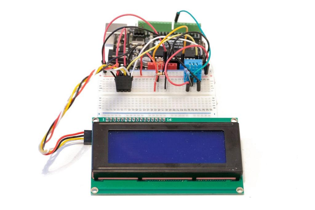
54 Now, if you have a third line available, like on the screen I used, you can directly print the light level as well on the third line: lcd.setcursor(1,2); lcd.print("light: "); lcd.print(light); lcd.print("%"); If you don t have a third line available on your LCD screen, you have several options. For example, you can just introduce some delay, clear the screen again, and print out the light level on the first line. We also introduce a 100 ms delay between each set of measurements and refresh of the LCD screen: delay(100); Note that the complete code for this chapter can be found inside the GitHub repository of the book: It s now time to test the project. Upload the code again to your Arduino board and wait for some time. You should be able to see the LCD printing the welcome message before moving on to display the measurements. Here is a picture of the project in action:

55 If it doesn t work, there are several things that you can check. The first one to check is that the code to test the different sensors is working correctly. So, do not hesitate to go back to the previous sections if necessary. Also, make sure that your LCD screen is correctly wired. Finally, make sure that you are using the correct LCD library for the screen you are using.
56 2.5 How to Go Further In this chapter, we built a simple home automation project: an LCD weather station based on Arduino. We interfaced several sensors with Arduino like digital humidity and temperature sensors. Then, we displayed these data on an LCD screen, which is also controlled by the Arduino board. There are several ways to use what you have learned in this chapter to build even more exciting projects. You can connect more sensors to the projects and display their measurements on the LCD screen. For example, you can connect a barometric pressure sensor to the project. You can also keep the same sensors and graphically display their measured data on an OLED screen.
57 Chapter 3 Building a Smart Lamp In this project, we are going to build a very common home automation system: a smart lamp. And by smart, I mean a lamp that automatically switches on when the ambient light level is low, and switches off again when the light level rises. To do so, we will use a relay module to control the lamp, and a photocell to measure the ambient light level. Since we will use the Arduino platform to do so, we are going to introduce some extra features. First, we will add a current sensor to the project, so we can know how much current and energy the lamp is consuming at a given moment. We will also add an LCD screen to the project, so you can instantly check the state of the relay, the energy consumption of the lamp, and the value of the ambient light level. As for the lamp itself, we are simply going to use a simple desk lamp, however, the principles of this project should work with any lamp.
58 3.1 Hardware & Software Requirements For this project, you will, of course, need an Arduino Uno or a similar board. For the relay module, I used a 5V relay module from Pololu, which nicely integrates a relay on a board, along with all the required components to the Arduino board. Here is a picture of the relay module I used: To measure the current flowing through the lamp, I used a board based on the AC712 sensor from ITead Studio. This sensor is really easy to use with Arduino, as it returns a voltage that is proportional to the measured current. With the correct formula, we will then infer the current flowing through the lamp from the voltage measured by the Arduino board. Of course, you can use other boards based on the same sensor. Here is a picture of the current-measuring board I used for this project:
59 For light levels measurements, I used a photocell with a 10K Ohm resistor. This will return a signal which is proportional to the incoming light level. You will also need an LCD screen to display the state of the relay, the power consumption of the device, and the light level. I used a 4x20 characters LCD so that I can display up to four lines at the same time. You can, of course, use a smaller LCD screen, but you will only be able to display the state of the relay and the current consumption at the same time, for example. The screen I used for this project uses an I2C interface to communicate with the Arduino board. I recommend using a screen with this interface as there are only two data pins needed to connect to the Arduino board. To connect the lamp to the project, I used a standard pair of power plugs with bare cables at the end, with one female socket (to plug the lamp in) and one male socket (to plug it into the power socket in the wall). Here is a picture of the cables I used:
60 Be careful in working on the cables as this is a high-voltage project. Finally, I used a breadboard and some jumper wires to make the different electrical connections. Here is a list of all components used in this project, along with the links where you can purchase them online: Arduino Uno ( Relay module ( Current sensor ( Photocell ( 10k Ohm resistor ( LCD display ( Breadboard ( Jumper wires ( For the lamp itself, I used a standard desk lamp (30W) for this project.* However, the relay module I used can support up to 1200W, so you can plug in more powerful lamps or devices if you wish. On the software side, all you need is the Arduino IDE, and the LiquidCrystal library for the LCD screen:
61 To install a library, simply put the folder in your /libraries/ folder of your main Arduino folder. *Note: In USA and Canada where 110VAC is used, standard wattage is 60W.
62 3.2 Hardware Configuration Let s now assemble the hardware for this project. We will do so in two parts. We will first connect the different components like the relay module to the Arduino board, and then we will connect the lamp to the project. The hardware connections for the first part are actually quite simple: we have to connect the relay module, the current sensor and the photocell. First, connect the Arduino Uno +5V pin to the red rail on the breadboard, and the ground pin to the blue rail. For the photocell, place the cell in series with the 10k Ohm resistor on the breadboard first. Then, connect the other end of the photocell to the red rail on the breadboard, and the other end of the resistor to the blue rail (ground). Finally, connect the common pin between the photocell and the resistor to the Arduino Uno analog pin A0. For the relay module, there are three pins you need to connect: VCC, GND and a signal pin, usually denoted as SIG. VCC needs to go to the Arduino 5V pin, so connect it to the red power rail. GND goes to the Arduino ground pin, so connect it to the blue power rail. Finally, connect the SIG pin to pin number 8 of the Arduino board. In a similar way, connect the current sensor module. It has three pins: VCC, GND, and OUT. As for the relay, VCC needs to go to the Arduino 5V pin, so connect it to the red power rail. GND goes to the Arduino ground pin, so connect it to the blue power rail. Then, connect the OUT pin to the analog pin A1 of the Arduino board. Now, we are going to connect the LCD screen. Since we are using an LCD with an I2C interface, there will only be two wires to connect for the signal, and two for the power. Connect the LCD pin called VCC to the red rail on the breadboard, and the GND pin to the blue rail on the breadboard. Then, connect the LCD pin SDA to the Arduino pin A4, and the SCL pin to Arduino pin A5. Here is a picture of the fully assembled project, without the lamp connected yet:
 go to the relay, then to the current sensor, and")
63 We are now going to connect the lamp to the hardware we already assembled. Basically, the idea is to have the main power supply (coming from the power socket in the wall) go to the relay, then to the current sensor, and finally to the lamp. Follow this schematic to make the required connections:
64 As it implies dangerous voltage levels (110v or 230v depending on where you are in the world), you should take some precautions at this point. You can find them in the introduction of this book. Note that you can test this project without having any device connected to the relay & the current sensor.
65 3.3 Testing the Relay It is now time to test the project. As the most important part of the project is the relay controlling the lamp, we are going to test there. We are simply going to switch the relay on and off continuously every 5 seconds just to check that the relay is working and that the connections with the lamp were correctly made. Here is the complete code for this part: // Simple sketch to test the relay // Relay pin const int relay_pin = 8; void setup() { pinmode(relay_pin,output); } void loop() { } // Activate relay digitalwrite(relay_pin, HIGH); // Wait for 5 seconds delay(5000); // Deactivate relay digitalwrite(relay_pin, LOW); // Wait for 5 seconds delay(5000); It starts by declaring on which pin the relay is connected to: const int relay_pin = 8; In the setup() function of the sketch, we set this pin as an output: pinmode(relay_pin,output); Then, in the loop() function of the sketch, we set this pin to a HIGH state, switching on the relay: digitalwrite(relay_pin, HIGH); Wait for 5 seconds: delay(5000); We then switch the relay off again: digitalwrite(relay_pin, LOW); And wait for 5 seconds before repeating the loop():
66 delay(5000); Note that the complete code for this chapter can be found on the corresponding folder inside the GitHub repository of the book: It s now time to test the sketch. Make sure that the lamp is correctly connected to the project, and that the male plug is plugged into the power socket in the wall. Then, upload the Arduino sketch to the board. You should see that every 5 seconds, the relay is switching, turning the lamp on and off. Be sure to fix the relay in a position such that it cannot be touched by accident.
67 3.4 Power Measurements & Automatic Lighting Control Let s now move to the main part of the project: building the Arduino sketch for our smart lamp. We basically need to continuously measure the light level and the current consumption of the lamp, print this data on the LCD screen, and change the state of the relay accordingly. Here is the complete code for this part: // Code for the smart lamp project // Libraries #include <Wire.h> #include <LiquidCrystal_I2C.h> // Relay state const int relay_pin = 8; boolean relay_state = false; // LCD display instance LiquidCrystal_I2C lcd(0x27,20,4); // Define measurement variables float amplitude_current; float effective_value; float effective_voltage = 230; // Set voltage to 230V (Europe) or 110V (US) float effective_power; float zero_sensor; void setup() { // Initialize the lcd lcd.init(); } // Print a message to the LCD. lcd.backlight(); lcd.setcursor(1,0); lcd.print("hello!"); lcd.setcursor(1,1); lcd.print("initializing "); // Set relay pin to output pinmode(relay_pin,output); // Calibrate sensor with null current zero_sensor = getsensorvalue(a1); // Clear LCD delay(2000); lcd.clear(); void loop() { // Measure light level float sensor_reading = analogread(a0); float light = (sensor_reading/1024*100); // Perform power measurement float sensor_value = getsensorvalue(a1); // Convert to current amplitude_current = (float)(sensor_value-zero_sensor)/1024*5/185* ; effective_value = amplitude_current/1.414; effective_power = abs(effective_value*effective_voltage/1000);
68 // Switch relay accordingly // If the light level is more than 75 %, switch the lights off if (light > 75) { digitalwrite(relay_pin, LOW); relay_state = false; } // If the light level is less than 50 %, switch the lights off if (light < 50) { digitalwrite(relay_pin, HIGH); relay_state = true; } // Update LCD screen // Display relay state lcd.setcursor(1,0); lcd.print("relay: "); if (relay_state) {lcd.print("on ");} else {lcd.print("off");} // Display energy consumption lcd.setcursor(1,1); lcd.print("power: "); lcd.print(effective_power); lcd.print("w"); // Display light level lcd.setcursor(1,2); lcd.print("light: "); lcd.print(light); lcd.print("%"); // Wait 500 ms delay(500); } // Get the reading from the current sensor float getsensorvalue(int pin) { int sensorvalue; float avgsensor = 0; int nb_measurements = 100; for (int i = 0; i < nb_measurements; i++) { sensorvalue = analogread(pin); avgsensor = avgsensor + float(sensorvalue); } avgsensor = avgsensor/float(nb_measurements); return avgsensor; } It starts by including the libraries required for the LCD: #include <Wire.h> #include <LiquidCrystal_I2C.h> We can create the instance of the LCD screen at this point. Note that you will have to modify the number of lines depending on your screen (4 for the screen I used): LiquidCrystal_I2C lcd(0x27,20,4); We need to declare the pin on which the relay is connected to, and a variable to store the state of the relay: const int relay_pin = 8; boolean relay_state = false;
69 Then, we have to create some variable to calculate the value of the current and power consumed by the lamp. Here, if you are using 110V instead of 230V, you will need to change the effective_voltage variable to the correct value: float amplitude_current; float effective_value; float effective_voltage = 230; // Set voltage to 230V (Europe) or 110V (US) float effective_power; float zero_sensor; Now, in the setup() function of the sketch, we initialize the LCD: lcd.init(); We also set the pin of the relay as an output: pinmode(relay_pin,output); Now, we need to calibrate the current sensor. The current sensor I used in this project is an analog sensor it returns a voltage proportional to the measured current. However, we need to know what is the voltage at which the sensor measures a null current. As the relay is switched off for now, we are sure to have no current flowing through the lamp. We get the null current value of the sensor by calling a function called getsensorvalue() on the pin A1: zero_sensor = getsensorvalue(a1); We won t see the details of this function, but it basically averages the reading on the analog pin over several measurements to have a stable reading as an output. We store the result in a variable called zero_sensor. Finally, to end the setup() function, we wait for some time before clearing the LCD screen: delay(2000); lcd.clear(); Now, in the loop() function of the sketch, we first read data from the analog pin A0, which returns a value from 0 to The resolution of the Analog-To-Digital converter of the Arduino Uno board is 10 bits, so we have 1024 values. Then, we divide this reading by 1024 and multiply it by 100 to have the light level as a percentage: float sensor_reading = analogread(a0); float light = sensor_reading/1024*100; Next, we get the reading from the current sensor using the same function we used before
70 (that averages the readings over several samples): float sensor_value = getsensorvalue(a1); From this value, we need to calculate the current, and then the power. First, we calculate the current using the calibration data we acquired before, and a formula given in the datasheet of the sensor. Then, we convert this current to its effective value by dividing it by the square root of 2. Finally, we calculate the effective power by multiplying the effective value of the current with the effective value of the voltage (and we also divide it by 1000 to get the result in Watts): amplitude_current = (float)(sensor_value-zero_sensor)/1024*5/185* ; effective_value = amplitude_current/1.414; effective_power = abs(effective_value*effective_voltage/1000); After that, we make a decision on whether to switch the relay on or not. If the light level is more than 75%, we switch the lamp off, as this means it is bright and we don t need lights: if (light > 75) { digitalwrite(relay_pin, LOW); relay_state = false; } If the light level is less than 50%, we switch the light on: if (light < 50) { digitalwrite(relay_pin, HIGH); relay_state = true; } Of course, you should use your own values for the two thresholds. For example, you can measure the light levels at night when the room is in an almost complete darkness with light only coming from your lamp and during the day with sunlight seeping into your room. Using these values, you can modify the two thresholds accordingly. Note that it is necessary to use two thresholds here. Remember that the reading from the photocell can oscillate a bit over time. And you don t want your lamp to continuously switch on and off if the reading from the photocell is around the threshold. Finally, we print data on the LCD screen. We first print the state of the relay: lcd.setcursor(1,0); lcd.print("relay: "); if (relay_state) {lcd.print("on ");} else {lcd.print("off");} Then, we print the effective power that we calculated from the current sensor reading:
71 lcd.setcursor(1,1); lcd.print("power: "); lcd.print(effective_power); lcd.print("w"); After that, we print the value of the ambient light level: lcd.setcursor(1,2); lcd.print("light: "); lcd.print(light); lcd.print("%"); We also wait 500 ms between each measurement: delay(500); Note that the complete code for this chapter can be found on the corresponding folder inside the GitHub repository of the book: It is now time to test our smart lamp. Make sure that all the connections are correctly made and the necessary codes have been uploaded to the Arduino board. Let s assume it is currently bright in your home: the relay should therefore be switched off. This is what the LCD screen should be displaying as pictured from my own project:

72 You can see that even if the light is off, the Arduino board measures some power consumed by the lamp. This is because the ACS712 current sensor output can pick up noise due to several factors like magnetic fields. Now, to simulate a dark room, I simply put a piece of tissue on top of the photocell. Instantly, the measured light level dropped, and the lamp switched on: Also note that the measured power was around 25W, which makes sense as the lamp is rated at 30W. In case your project is not working at this point, there are several things you can check. First, make sure that the relay, the LCD screen and the sensors are correctly connected to your Arduino board. Also make sure to modify the code accordingly if you are using a smaller LCD screen than the one I used on this project.
73 3.5 How to Go Further Let s summarize what we learned in this project. We built a smart lamp using Arduino and some basic components. The lamp is now automatically switching on or off accordingly to the ambient light level. We also added a twist to the project by adding a current measurement device, which tells us how much power the lamp is consuming when it is on. We also added an LCD screen which displays the state of the lamp, the power consumption and the ambient light level. You can improve this project by using more sensors. For example, you can combine it with the project in the previous chapter and have more sensor measurements displayed on the LCD screen. You can also add more controls to the lamp to make it even smarter. For example, you can add a motion sensor to the mix to switch the light on when the light level is low or when some motion is detected in the room
74 Chapter 4 XBee Motion Sensors In the previous chapters of this book, we built self-contained home automation systems, which could work completely autonomously, without communicating with the external world. However, that s not how most commercial home automation systems work. Usually, the components in these systems communicate with each other wirelessly. And that s exactly what we are going to do in the remaining chapters of this book. To start with wireless home automation systems based on Arduino, we are going to use a technology that is widely used in home automation systems: XBee. XBee is a technology built on the ZigBee standard, which defines low-power, digital radio communications based on the IEEE standard. It was made for systems that require small data transfer (like sensors), running on batteries, and that have to be secure. Needless to say, it s the perfect technology for home automation systems. In this project, we are going to take a new look at a project we have already built: the simple alarm based on Arduino and a PIR motion sensor. We are going to take the same sensor and Arduino, and add an XBee module to it. We are also going to build an interface on your computer, so you can monitor the state of many of these XBee motion sensors from your web browser.
75 4.1 Hardware & Software Requirements Let s first see what we need for this project. There are two distinct things that we will have to build in this project. On one side, we will have the XBee motion sensors, and the other side, we will have one XBee module that will be connected to your computer via USB. For one XBee motion sensor, you will first need an Arduino board. I used again an Arduino Uno board for this project. Then, you need a motion sensor. For this project, I used the same PIR motion sensor that we already used in the first project of this book. Next, you need to interface the XBee module with the Arduino board. To connect the XBee module to Arduino, I used a SparkFun XBee shield for Arduino. It integrates a socket for any XBee module, and also a switch to connect and disconnect the XBee module from the Arduino microcontroller Serial port. We ll see later in this chapter that it is very useful. For the XBee modules, I used Series 2 XBee modules, with a wire antenna. Series 1 are much easier to use, but Series 2 add the possibility to create meshed networks, and to target a given module, which is something we will use in this chapter. Here is a picture of the Arduino Uno board with the XBee shield on it, with one XBee module already plugged in:
 Arduino XBee shield (https://www.sparkfun.com/products/10854) XBee Series 2 module with wire antenna (https://www.sparkfun.com/products/11215) Jumper wires (http://www.")
76 Here is a list of all components for one XBee motion sensor, along with the links where you could purchase them online: Arduino Uno ( PIR motion sensor ( Arduino XBee shield ( XBee Series 2 module with wire antenna ( Jumper wires ( Now, we need to get your computer some XBee connectivity. Indeed, unlike Bluetooth or WiFi, computers don t come with built-in XBee connectivity. To connect an XBee module to my computer, I chose a USB explorer module from Sparkfun. You can mount any XBee module on it, and you can connect it via USB to your computer. It behaves like a Serial port, which means you can send messages to it via the Arduino IDE serial monitor. For the XBee module, I chose the same module as for the XBee motion sensors. Here is a picture of the XBee explorer board with the XBee module mounted on it:
77 To use XBee on your computer, you will need these components: USB XBee explorer board ( XBee Series 2 module with wire antenna ( On the software side, you need to have the latest version of the Arduino IDE installed on your computer, as well as the arest library for Arduino which you can find on the following link: To install a given library, simply extract the folder in your Arduino /libraries folder (or create this folder if it doesn t exist yet).
78 4.2 Building an XBee Motion Sensor We are now going to see how to build one XBee motion sensor. If you want to use many of them for this project, just repeat the following steps for each module. The configuration of this project is actually very simple. First, plug the XBee shield on the Arduino board, and plug one XBee module on the shield. For the PIR motion sensor, connect the GND pin to the Arduino ground, VCC to the Arduino 5V pin, and SIG pin to the Arduino pin 8. You should end up with something similar to the following picture: You will also need to put the switch on the XBee shield to the correct position. At this point, we want to program the Arduino board to set the switch such that the XBee module is not connected to the Serial port of the Arduino microcontroller. To do so, put the switch on DLINE :

79 Finally, also connect the XBee explorer board with the XBee module on it to your computer.
80 4.3 Testing the Motion Sensor We are now going to test the motion sensor. We will write a simple sketch that continuously prints the status of the motion sensor to the Serial port of the Arduino. For now, leave the switch of the XBee shield to DLINE. Here is the complete sketch for this part: // Simple motion sensor int sensor_pin = 8; void setup() { Serial.begin(9600); } void loop() { } // Read sensor data int sensor_state = digitalread(sensor_pin); // Print data Serial.print("Motion sensor state: "); Serial.println(sensor_state); delay(100); The sketch starts by declaring which pin the PIR motion sensor is connected to: int sensor_pin = 8; In the setup() function of the sketch, we start the Serial port: Serial.begin(9600); In the loop() function of the sketch, we read the PIR motion sensor pin: int sensor_state = digitalread(sensor_pin); Finally, we print the state of that pin every 100ms on the Serial port: Serial.print("Motion sensor state: "); Serial.println(sensor_state); delay(100); Note that the complete code for this section can be found inside the GitHub repository of the book: It s now time to test this first sketch of this chapter. Upload the sketch to the Arduino board, and open the Serial monitor (making sure that the Serial speed is set to 9600). You can pass your hand in front of the sensor, and you should see that the state of sensor
81 changes: Motion sensor state: 0 Motion sensor state: 0 Motion sensor state: 0 Motion sensor state: 0 Motion sensor state: 1 Motion sensor state: 1 Motion sensor state: 1 Motion sensor state: 1 Motion sensor state: 0 Motion sensor state: 0 Motion sensor state: 0 If it is not working at this point, there are several things you can check. First, make sure that you have correctly plugged the motion sensor into the Arduino board as defined earlier in the chapter. Then, make sure that you have correctly uploaded the latest version of the code.
82 4.4 Using the XBee Module In this section, we are going to use the XBee module that is sitting on the XBee shield to access the motion sensor wirelessly. We are going to write a simple Arduino sketch which makes use of the arest library to receive and handle requests coming from the outside. But the first thing we have to do is to configure our XBee radios. By default, all XBee modules are configured to use the same communication channel called the PAN (Personal Area Network) ID. This is good to test them out of the box, but this is not good at all when you actually want to use them in your home. If you leave them on the default PAN ID, they will broadcast messages on all devices with the same PAN ID, including those of your neighbors! Worse, somebody could actually hack into your XBee sensors from the outside. We also need to set our radios correctly by giving them roles. In a Series 2 XBee network, one of the radios should be the coordinator of the network. Without one, it will simply not work at all. The other radios can be either routers that can relay messages, or End Devices that simply get messages from the network. Because we have a simple network here, we will simply configure the XBee radio connected to our computer to be a coordinator, and the other to be end devices. Therefore, we need to change all these parameters. This is actually easy to do using the official software to configure XBee modules called XCTU. You can download it at the following address: Once it is installed, open the software, and connect the XBee module you want to configure to the XBee explorer module which is connected via USB to your computer. By looking at the Serial port of the explorer module, you can access the settings of this XBee module. First, look for PAN ID in the Radio Configuration window:


83 From this menu, you can set the PAN ID for the XBee module that is currently plugged inside the XBee explorer board. Simply repeat the operation for every XBee module you want to configure. Now, we will give roles to our XBees. Plug the module which will be the coordinator into the XBee explorer. Add the device using the left menu again, and then click on the update firmware button on the top menu bar (the one with a little arrow going into the chip). From there, you will be able to select the firmware we want for our coordinator XBee. We have to select XB24-ZB on the left, and then ZigBee Coordinator API from the list. Select the latest firmware version, and confirm our choice: After a while, you will see that your device is now configured as an XBee coordinator in


84 API mode: Still for this XBee device, we need to go down the list of parameters, and choose 2 in the API Enable parameter, and write the parameter into the XBee radio with the right button: Finally, we need to configure the other XBee radios as end points. For each of them, connect them to the XBee explorer, click on the button to write the firmware again, select XB24-ZB on the left, and select ZigBee End Device AT from the list. Confirm, and this is what you should get: We are now going to build this Arduino sketch on top of the test sketch, so I will only define the code additions here. Here is the complete sketch for this part: // Libraries #include <SPI.h> #include <arest.h> // Motion sensor ID char * xbee_id = "2"; // Create ArduREST instance
85 arest rest = arest(); void setup() { } // Start Serial Serial.begin(9600); // Give name and ID to device rest.set_id(xbee_id); rest.set_name("motion2"); void loop() { } // Handle REST calls rest.handle(serial); This sketch starts by including the correct libraries for the sketch: #include <arest.h> We also define the ID of the sensor. This is really useful if you have many motion sensors in your home. Make sure to give them different IDs: String xbee_id = "1"; We also need to create an instance of the arest library: arest rest = arest(); In the setup() function of the sketch, we start the Serial port. Note that it is really important to use a speed of 9600 here as it is the default speed of XBee modules: Serial.begin(9600); We also set the ID of the device that we defined before: rest.set_id(xbee_id); Finally, in the loop() function of the sketch, we simply handle the requests coming from the Serial port using the arest library: rest.handle(serial); Note that the complete code for this section can be found inside the GitHub repository of the book: It s now time to test this sketch. Upload the sketch to the Arduino board. Then, put the switch of the XBee shield to UART so that the XBee module can directly communicate
86 with the Arduino microcontroller via the Serial port. Note that if you need to program the Arduino board again, you need to switch it back to DLINE. You should also make sure that the XBee explorer module is plugged in your system. If you are running under Windows or OS X, you might need additional drivers to install for this USB board. You can find all the download and installation details here: Now, you need to locate the Serial port corresponding to the XBee explorer board connected to your computer. You can do so by looking at the Tools>Serial Port menu of the Arduino IDE. For example, mine is called /dev/cu.usbserial-a702lf8b. On Windows, it will look like COM3. Also write it down for you will need it later when building the interface for your motion sensors. Open the Serial monitor of the Arduino IDE. Make sure that the speed is set to 9600, and that the end line character is set to Carriage return. Note that because we are now connected to the XBee explorer board, all commands that you are sending now are being sent to all XBee modules in your home. In the Serial monitor, type: /id This will simply query the ID of the all XBee boards that are in your home. When I tested my project, I only had one in my home. It responded with: {"id": "1", "name": "", "connected": true} After this step, we are going to read the status of the motion sensor. Remember, it is connected to pin number 8. To read from this pin, simply type: /digital/8 The sensor should answer with the following message: {"return_value": 1, "id": "1", "name": "", "connected": true} If the sensors are answering to the queries at this point, it means that they are working correctly and that you can access them wirelessly. In case it is not working at this point, there are several things you can check. First, make sure that you have uploaded the latest version of the code. You can find it inside the GitHub repository of the book. Also, make sure that the XBee explorer board is correctly
87 plugged into your computer by checking that the proper drivers are installed. Finally, make sure that the XBee shield is set to the UART position.
88 4.5 Building the Central Interface We are now going to build the interface that you will use to monitor the motion sensors from your computer. Using this interface, you will be able to see the state of each sensor via XBee, right in your web browser. The interface that we are going to develop is based on Node.js, which allows the coding of server-side applications in JavaScript. First, we are going to code the main file called app.js, which we will run later using the node command in a terminal. Here is the complete code for this file: // Modules var express = require('express'); var app = express(); // Define port var port = 3000; // View engine app.set('view engine', 'jade'); // Set public folder app.use(express.static( dirname + '/public')); // Rest var rest = require("arest")(app); rest.adddevice('xbee','/dev/tty.usbserial-a702lf8b'); // Serve interface app.get('/', function(req, res){ var devices = rest.getdevices(); res.render('interface', {devices: devices}); }); // Start server app.listen(port); console.log("listening on port " + port); It starts by importing the express module: var express = require('express'); Then, we create our app based on the express framework, and the set the port to 3000: var app = express(); var port = 3000; We also need to tell our software where to look for the graphical interface that we are going to code later. We also set the default view engine to Jade, which as we will see is a simplified way to code in HTML: app.set('view engine', 'jade'); app.use(express.static( dirname + '/public'));
89 At this point, we also import the node-arest module, that will handle all the communication between the interface and the module. Here, we also need to define the Serial port on which the XBee explorer module is connected to: var rest = require("arest")(app); rest.adddevice('xbee','/dev/tty.usbserial-a702lf8b'); This will automatically look for all XBee modules in the same network as our coordinator radio, and add them automatically to the server so we can access them from the interface. Now, we are going to build the main route of our server. We define this route by linking the root URL of our server to the corresponding Jade file. Because we want to build the interface automatically depending on how many devices are present, we need to get all the devices first, and then transmit this data to the Jade file so it can be rendered correctly: app.get('/', function(req, res){ var devices = rest.getdevices(); res.render('interface', {devices: devices}); }); Finally, still in this app.js file, we start the app with the port we defined before, and write a message in the console: app.listen(port); console.log("listening on port " + port); This was for the main server file. Now, we are going to build the interface itself. Let s see the content of this Jade file first. This file is located in the /views folder of our project. Here is the complete code for this file: doctype html head title XBee motion sensors link(rel='stylesheet', href='//maxcdn.bootstrapcdn.com/bootstrap/3.3.0/css/bootstrap.min.css') script(src=" script(src="/js/interface.js") body.container.row h1 XBee motion sensors if (devices!= '[]') each device in devices if (device.type == 'xbee').row.col-md-4 h3 Sensor #{device.id}.col-md-4 h3.display(id=device.id) Jade is basically a template language that allows to write HTML with less code than HTML itself, and also to insert some code right into the interface file, to generate HTML
90 depending on some variables. The file starts by importing the different JavaScript files which will handle the click on the interface, and send the correct commands to the Arduino board: script(src=" script(src="/js/interface.js") We will also use the Twitter Bootstrap CSS framework to give our interface a better look: link(rel='stylesheet', href='//maxcdn.bootstrapcdn.com/bootstrap/3.3.0/css/bootstrap.min.css') The main part of the interface consists in going through the list of all sensors that were detected before, and build a row for each sensor. This is done by the following piece of code: if (devices!= '[]') each device in devices if (device.type == 'xbee').row.col-md-4 h3 Sensor #{device.id}.col-md-4 h3.display(id=device.id) Next, we are going to have a look at the code inside the interface.js file, which defines how the interface of the project is working. It will make the queries to the board via the Node.js server, and update the interface accordingly. This file is located in the public/js folder of the interface. Here is the complete code for this file: $(document).ready(function() { $.get('/devices', function( devices ) { // Set inputs for (i = 0; i < devices.length; i++){ } // Get device var device = devices[i]; // Set input $.get('/' + device.name + '/mode/8/i'); setinterval(function() { for (i = 0; i < devices.length; i++){ // Get device var device = devices[i]; // Get data $.get('/' + device.name + '/digital/8', function(json_data) { // Update display if (json_data.return_value == 0){ $("#" + json_data.id).html("no motion"); $("#" + json_data.id).css("color","red");
91 } else { $("#" + json_data.id).html("motion detected"); $("#" + json_data.id).css("color","green"); } } }); }); }); }, 2000); The main part of this JavaScript file is programmed to continuously check the states of the sensors by sending them queries. This is done inside a setinterval() function: setinterval(function() { Inside this function, we go through all devices, and send them a command to read the pin on which the motion sensors are connected to: $.get('/' + device.name + '/digital/8', function(json_data) { The arest library always return data in a JSON container, so it is really easy to access this data within JavaScript. We need to know the state of that motion sensor. This is stored in the return_value field. If the data in this field is equal to 0, we set the indicator of this sensor to No motion in red. Otherwise, we set it to green with the Motion detected message, meaning motion was detected by this sensor: if (json_data.return_value == 0){ $("#" + json_data.id).html("no motion"); $("#" + json_data.id).css("color","red"); } else { $("#" + json_data.id).html("motion detected"); $("#" + json_data.id).css("color","green"); } After that, we close the setinterval() function, repeating the loop every two seconds: }, 2000); Note that the complete code for this section can be found inside the GitHub repository of the book: It s now time to test the interface. Make sure that you download all the files from the GitHub repository, and update the code with your own data if necessary, like the Serial port corresponding to your XBee explorer board. Also, make sure that the Arduino board is programmed with the code we saw earlier in this chapter.
92 Go to the folder of the interface with a terminal and type the following command to install the node-arest, jade & express modules: sudo npm install arest express jade Note that if you are under Windows, you have to leave out the sudo in front of the commands. It is also recommended to use the Node.js command prompt. Finally, you can start the Node.js server by typing: sudo node app.js You should be greeted with the following message in the terminal: Listening on port 3000 You should also see in the terminal that your XBee radios are automatically discovered and added to the system. You can now go to the your web browser and type: localhost:3000 You should see the interface of our project being displayed: To test this project, I used two motion sensors. To illustrate the behavior of one module, I simply passed my hand in front of the sensor with ID number 1. The corresponding indicator immediately turned to green. Of course, if you have more sensors, the interface will automatically be modified. If it is not working at this point, there are several things you can check. First, make sure that you have downloaded the latest version of the code from the GitHub repository of the book. Also, make sure that you have correctly modified the files to use your own settings, like the Serial port for your XBee explorer module. Finally, make sure you have installed the required Node modules with npm before starting the web interface.
93 4.6 How to Go Further Let s summarize what we learned in this project. We took the project we already built in Chapter 1 and added wireless capabilities to it using XBee. We learned how to interface XBee modules with Arduino, and build XBee motion sensors with it. We were able to monitor the state of several wireless motion sensors from your web browser. There are of course many ways to go further with this project. The easiest thing is to add more motion sensors to the project to cover all your home. You can also add different kinds of digital sensors to the project. For example, you can use the same code to monitor the state of contact sensors which you can put on doors and windows. You can also use the same principles seen in this chapter to monitor other data using XBee, like measurements coming from temperature sensors.
94 Chapter 5 Bluetooth Weather Station In this chapter, we are going to give wireless capabilities to the project we already saw in Chapter 2. We are going to build a wireless weather measurement station using Bluetooth. The station will measure temperature, humidity and light level in the room where the project is located, and display this data on an LCD screen. However, in this new project we will add a Bluetooth module to the project to be able to monitor the measured data from anywhere in your home. We are going to build an interface on your computer so you can check the measurements done by the station inside your web browser.
95 5.1 Hardware & Software Requirements For this project, you will of course need an Arduino Uno board. You can also use other Arduino boards like an Arduino Mega or Leonardo, it will work just fine as well. For temperature and humidity measurements, you will also need a DHT11 sensor, along with a 4.7K resistor. You can also use a DHT22 sensor which is more precise, you will only have one line of code to change. For light levels measurements, I used a photocell with a 10K Ohm resistor. This will return a signal which is proportional to the incoming light level. You will also need a LCD screen to display the measurements. I used a 4x20 characters LCD so I can display up to four different measurements at the same time. You can of course use a smaller LCD screen, but you will only be able to display the temperature & humidity at the same time, for example. The screen I used for this project is also using an I2C interface to communicate with the Arduino board. I really recommend using a screen which such an interface, as there are only two data pins to connect to the Arduino board in order to use the LCD. For the Bluetooth module, I used a Bluetooth 2.1 module from Adafruit. This module interfaces directly with the Serial port of the Arduino board, which makes it very convenient. You can basically use any module (include Bluetooth 4.0 modules) that can interface directly with the Serial port of the Arduino microcontroller. Modules that require their own libraries for Arduino (for example based on the nrf8001 chip) won t work out of the box for this project. This is a picture of the module I used:
 DHT11 sensor (http://www.adafruit.com/product/386) Photocell (http://www.")
96 Finally, I used a breadboard and some male-male jumper wires to make the different electrical connections. This is a list of all components used in this project, along with links to purchase them online: Arduino Uno ( DHT11 sensor ( Photocell ( 10k Ohm resistor ( LCD display ( Adafruit EZ-Link Bluetooth module ( Breadboard ( Jumper wires ( You will need the arest library for Arduino which you can find on the following link: You will also need the library for the DHT sensor:
97 And the LiquidCrystal library for the LCD screen: To install a library, simply put the folder in your /libraries/ folder of you main Arduino folder.

98 5.2 Building the Bluetooth Weather Station The hardware connections for this project are actually quite simple: we have to connect the DHT11 sensor, the part responsible for the light level measurement with the photocell, the LCD screen, and finally the Bluetooth module. To help you out, the following picture summarizes the hardware connections, without the LCD screen shown: This image was created with Fritzing ( First, connect the Arduino Uno +5V pin to the red rail on the breadboard, and the ground pin to the blue rail. To know which pin to connect for the DHT11 sensor, this picture can help you out:
99 Then, connect pin number 1 of the DHT11 sensor (VCC)to the red rail on the breadboard, and pin number 4 (GND) the blue rail. Also connect pin number 2 of the sensor to pin number 7 of the Arduino board. To finish up with the DHT11 sensor, connect the 4.7k Ohm between pin number 1 and 2 of the sensor. For the photocell, first place the cell in series with the 10k Ohm resistor on the breadboard. Then, connect the other end of the photocell to the red rail on the breadboard, and the other end of the resistor to the ground. Finally, connect the common pin of the resistor & the photocell to the Arduino Uno analog pin A0. Now, we are going to connect the LCD screen. As we are using a LCD with an I2C interface, there will only be two wires to connect for the signal, and two for the power. Connect the LCD pin called VCC to the red rail on the breadboard, and the GND pin to the blue rail on the breadboard. Then, connect the LCD pin SDA to the Arduino pin A4, and the SCL pin to Arduino pin A5. The Bluetooth module is also quite easy to connect. First, the power supply. Connect the Vin pin (or VCC, depending on your module) to the red power rail, and the GND pin to the blue power rail. Then, we have to connect the Serial port of the Bluetooth module to
100 the Arduino board. Connect the RX pin of the module to the TX pin (pin number 1) of the Arduino board, and the TX pin of the module to the RX pin (pin number 0) of the Arduino board. This is a picture of the fully assembled project so you can have an idea on how the complete project looks like: This picture is a closer look at the Bluetooth module on the breadboard:
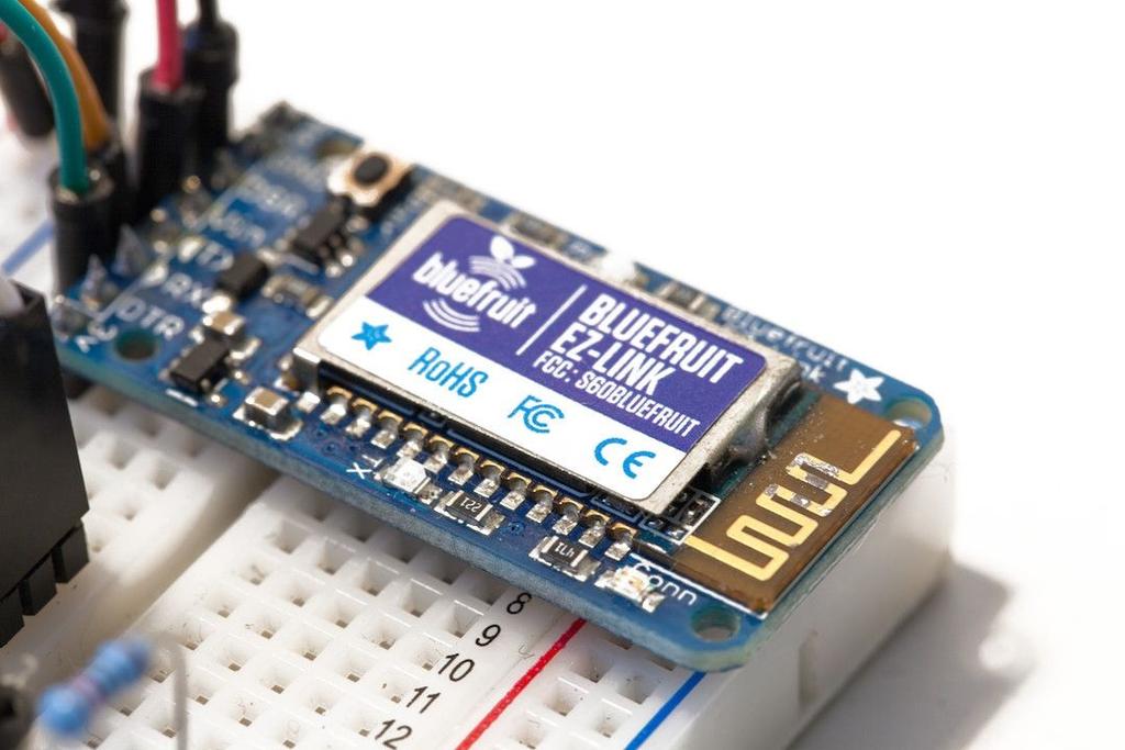
101

102 5.3 Pairing the Bluetooth Module Before we proceed further, we are going to test our assembled hardware. We already made the test of the different sensors in Chapter 2, so you can refer to this chapter to test the sensors of the project. Here, we are simply going to check if we can access the Bluetooth module. Simply power up the project, for example by connecting a USB cable between the Arduino board and your computer. Then, go the Bluetooth preferences of your computer, and you should see the Bluetooth module appearing in the list of nearby Bluetooth devices: Click on Pair to pair the Bluetooth module with your computer. Then, go over to your Arduino IDE. Open the Tools>Serial Port list. You should see that a new Serial port is available, containing AdafruitEZ in the name of the Serial port (or the name of the Bluetooth module that you are using): If this is not the case, simply close and re-open the Arduino IDE. If the Bluetooth module is correctly paired with your computer, there is no reason for it not to appear in your Arduino IDE.
103 5.4 Remote Temperature Measurements Now that we are sure that we can pair the Bluetooth module with your computer, we are going to write a sketch to receive commands via Bluetooth. To do so, we will use the arest library again, that we already used in the previous chapter to handle commands coming via Bluetooth. This is the complete code for this part: // Code to measure data & make it accessible via // Libraries #include <Wire.h> #include <LiquidCrystal_I2C.h> #include "DHT.h" #include <arest.h> // DHT sensor #define DHTPIN 7 #define DHTTYPE DHT11 // LCD display instance LiquidCrystal_I2C lcd(0x27,20,4); // DHT instance DHT dht(dhtpin, DHTTYPE); // Create arest instance arest rest = arest(); // Variables to be exposed to the API int temperature; int humidity; int light; void setup() { // Start Serial Serial.begin(115200); } // Expose variables to REST API rest.variable("temperature",&temperature); rest.variable("humidity",&humidity); rest.variable("light",&light); // Set device name & ID rest.set_id("1"); rest.set_name("weather_station"); // Initialize the lcd lcd.init(); // Print a message to the LCD. lcd.backlight(); lcd.setcursor(1,0); lcd.print("hello!"); lcd.setcursor(1,1); lcd.print("initializing "); // Init DHT dht.begin(); // Clear LCD lcd.clear(); void loop() {
104 // Measure from DHT temperature = (int)dht.readtemperature(); humidity = (int)dht.readhumidity(); // Measure light level float sensor_reading = analogread(a0); light = (int)(sensor_reading/1024*100); // Handle REST calls rest.handle(serial); // Display temperature lcd.setcursor(1,0); lcd.print("temperature: "); lcd.print((int)temperature); lcd.print((char)223); lcd.print("c"); // Display humidity lcd.setcursor(1,1); lcd.print("humidity: "); lcd.print(humidity); lcd.print("%"); // Display light level lcd.setcursor(1,2); lcd.print("light: "); lcd.print(light); lcd.print("%"); // Wait 100 ms delay(100); } First, we need to include the required libraries for the project: #include <Wire.h> #include <LiquidCrystal_I2C.h> #include "DHT.h" #include <arest.h> We also have to define the pins on which the DHT sensor is connected to, and the type of the sensor: #define DHTPIN 7 #define DHTTYPE DHT11 We also need to create an instance of the LCD screen: LiquidCrystal_I2C lcd(0x27,20,4); Then, we have to create an instance of the DHT sensor: DHT dht(dhtpin, DHTTYPE); We also need to create an instance of the arest library: arest rest = arest(); Finally, just before the setup() function, we declare the different variables that will store
105 the measurements done by the weather station: int temperature; int humidity; int light; Now, in the setup() function of the sketch, we initialize the Serial port: Serial.begin(115200); Note that here, it is important to start it using bps as the Bluetooth module is operating at this speed. If the Bluetooth module you are using for this project is different, you need to change the Serial speed accordingly. Then, we have to expose the different measurement variables to the arest API, so we can access them via Bluetooth: rest.variable("temperature",&temperature); rest.variable("humidity",&humidity); rest.variable("light",&light); We also give an ID to the station, and some name: rest.set_id("1"); rest.set_name("weather_station"); Finally, to end the setup() function, we initialize the LCD screen and start the DHT sensor: lcd.init(); dht.begin(); Now, in the loop() function, we will first make the required measurements, handle the calls coming from the Bluetooth module, and finally display the measurements on the LCD screen. First, we get the measurements from the DHT sensor: temperature = (int)dht.readtemperature(); humidity = (int)dht.readhumidity(); We also get data from the photocell, and convert this result to %: float sensor_reading = analogread(a0); light = (int)(sensor_reading/1024*100); After that, we handle the requests coming from the Bluetooth module: rest.handle(serial); Finally, we end the sketch by displaying the different measurements on the LCD screen.
106 For example, on the first line of the screen I chose to display the temperature: lcd.setcursor(1,0); lcd.print("temperature: "); lcd.print((int)temperature); lcd.print((char)223); lcd.print("c"); Note that the complete code for this chapter can be found inside the GitHub repository of the book: It s now time to test the project. But first, we need to do a little hardware modification. Indeed, the Serial port is currently directly connected to the Bluetooth module, which prevents us from programming the Arduino board using the USB cable. So first, disconnect the wires going from the Bluetooth module to the Arduino board (TX & RX). Now, you can upload the sketch to the Arduino board as usual. When this is done, reconnect the TX and RX wires between the Bluetooth module and the Arduino module. When this is done, you can pair again the Bluetooth module with your computer, and then select the Bluetooth Serial port (the one starting with cu. and containing the name of your module). Then, open the Serial monitor, and select the correct Serial speed that you defined in the sketch. Also make sure that the end line character is set to Carriage return, just next to the Serial speed. You can now simply type: /id The project should answer with the ID & name of the weather station: {"id": "1", "name": "weather_station", "connected": true} We can also test the readout of one variable. For example, the light level with the following command: /light You should get the answer from the project: {"light": 83, "id": "1", "name": "weather_station", "connected": true} Of course, at the same time the project should print all the measurements on the LCD screen:

107 If it is not working at this point, there are several things you can check. First, make sure that you correctly assembled the hardware, as we saw earlier in this chapter. Also, make sure that you correctly uploaded the code for this part, and that you connected again the Bluetooth module to your Arduino board via the Serial pins.
108 5.5 Building the Server Interface We are now going to build an interface for our Bluetooth weather station, so we can monitor the different measurements made by the station from a web browser. We will still be able to check the measurements from the LCD screen, but we will also have the possibility to watch these measurements remotely. Note that this part is similar to what we did in the previous chapter for the interface. If you feel confident with it, you can skip the beginning of the code walk through. As for the other interfaces we developed in this book, the interface we are going to develop is based on Node.js. First, we are going to code the main file called app.js, which we will run later use the node command in a terminal. This is the complete code for this file: // Modules var express = require('express'); var app = express(); // Define port var port = 3000; // View engine app.set('view engine', 'jade'); // Set public folder app.use(express.static( dirname + '/public')); // Rest var rest = require("arest")(app); rest.adddevice('serial','/dev/tty.usbmodem1a12121', ); // Serve interface app.get('/', function(req, res){ res.render('interface'); }); // Start server app.listen(port); console.log("listening on port " + port); It starts by importing the express module: var express = require('express'); Then, we create our app based on the express framework, and the set the port to 3000: var app = express(); var port = 3000; We also need to tell our software where to look for the graphical interface that we are going to code later, and we also set Jade as our default view engine: app.use(express.static( dirname + '/public'));
109 app.set('view engine', 'jade'); We also need to import the node-arest module, and also add the device connected to your Bluetooth Serial port. Note that here, you need to insert your own Serial port address so the interface can communicate with your Bluetooth module: var rest = require("arest")(app); rest.adddevice('serial','/dev/tty.adafruitez-link06d5-spp', ); Now, we are going to build the main route of our server. We define this route by linking the root URL of the server to the corresponding Jade file: app.get('/', function(req, res){ res.render('interface'); }); Finally, still in this app.js file, we start the app with the port we defined before, and write a message in the console: app.listen(port); console.log("listening on port " + port); This was for the main server file. Now, we are going to build the interface itself. Let s see the content of the Jade file first. This file is located in the /view folder of our project. This is the complete code for this file: doctype html head title Bluetooth Weather Station link(rel='stylesheet', href='/css/interface.css') link(rel='stylesheet', href=" script(src=" script(src="/js/interface.js") body.container h1 Bluetooth Weather Station.row.voffset.col-md-6.display#temperatureDisplay Temperature:.col-md-6.display#humidityDisplay Humidity:.row.col-md-6.display#lightDisplay Light level:.col-md-6.status#status Station Offline The file starts by importing the different JavaScript files that will handle the click on the interface, and send the correct commands to the Arduino board: script(src=" script(src="/js/interface.js") We also use the Bootstrap framework again to give a better look to our interface:
110 link(rel='stylesheet', href='/css/interface.css') link(rel='stylesheet', href=" Then, the main part of the interface will be built of several blocks that show the state of each sensor. To see that one sensor is active, we will simply change the color of the indicator from gray to orange. This is the code for the sensors:.row.voffset.col-md-6.display#temperaturedisplay Temperature:.col-md-6.display#humidityDisplay Humidity:.row.col-md-6.display#lightDisplay Light level:.col-md-6.status#status Station Offline Now, we are going to have a look at the code inside the interface.js file, which defines how the interface of the project is working. It will make the queries to the board via the Node.js server, and update the interface accordingly. This file is located in the public/js folder of the interface. This is the complete code for this file: var devices = []; $.get('/devices', function( json_data ) { devices = json_data; }); $(document).ready(function() { function updatesensors() { } }); // Update light level and status $.get('/' + devices[0].name + '/light', function(json_data) { console.log(json_data.light); $("#lightdisplay").html("light level: " + json_data.light + "%"); // Update status if (json_data.connected == 1){ $("#status").html("station Online"); $("#status").css("color","green"); } else { $("#status").html("station Offline"); $("#status").css("color","red"); } $.get('/' + devices[0].name + '/temperature', function(json_data) { $("#temperaturedisplay").html("temperature: " + json_data.temperature + " C"); $.get('/' + devices[0].name + '/humidity', function(json_data) { $("#humiditydisplay").html("humidity: " + json_data.humidity + "%"); }); }); }); settimeout(updatesensors, 500); setinterval(updatesensors, 5000);
111 It starts by defining that we are using Serial communications, and specifying which Serial port is used and the Serial speed: type = 'serial'; address = '/dev/cu.adafruitez-link06d5-spp'; speed = ; Note that here you will have to modify the address variable with your own Serial port address of the Bluetooth module you are using. The main part of this JavaScript file consists in continuously requesting the value of the different measurement variables on the board, by sending queries via the arest API. This is done inside a setinterval() function: setinterval(function() { Inside this function, we send a request via our computer Bluetooth connection. For example, to get the light level measured by the Arduino board, we send the same /light command that we used before: $.get('/' + devices[0].name + '/light', function(json_data) { The arest library always return data in a JSON container, so it is really easy to access this data within JavaScript. When we have this data, we can update the corresponding display accordingly: $("#lightdisplay").html("light level: " + json_data.light + "%"); The same is done with the temperature & humidity measurements. We also need to know if the station is online or not. To do so, we read the field called connected when a measurement is coming back, and we update the corresponding display inside the interface: if (json_data.connected == 1){ $("#status").html("station Online"); $("#status").css("color","green"); } else { $("#status").html("station Offline"); $("#status").css("color","red"); } After that, we close the setinterval() function, repeating this loop every 5 seconds. Note that the complete code for this chapter can be found inside the GitHub repository of the book:
112 It s now time to test the interface. Make sure that you download all the files from the GitHub repository, and update the code with your own data if necessary, like the Serial port corresponding to your Bluetooth module. Also, make sure that the Arduino board is programmed with the code we saw earlier in this chapter. Then, go to the folder of the interface with a terminal, and type the following command to install the arest, express and Jade modules: sudo npm install arest jade express Note that if you are under Windows, you have to leave out the sudo in front of the commands, and it is recommended to use the Node.js command prompt. Finally, you can start the Node.js server by typing: node app.js You should be greeted with the following message in the terminal: Listening on port 3000 You can now go to the your web browser, and type: localhost:3000 After a while (the Bluetooth 2.1 connection can be pretty slow), you should see the interface of the weather station being displayed: You can of course double check with the display of the measurements on the LCD screen, to be sure that they match with what the interface is displaying. If it is not working at this point, there are several things you can check. First, make sure that you downloaded the latest version of the code from the GitHub repository of the book. Also made sure that you correctly modified the files to put your own settings, like the Serial port for your Bluetooth module. Finally, make sure to install the required Node.js modules with npm before starting the web interface.
113 5.6 How to Go Further Let s summarize what we learned in this project. We took the project we already built in Chapter 2 and added wireless capabilities to it using Bluetooth. We learned how to interface a Bluetooth module with Arduino, and build a wireless weather station with it. We were able to monitor the measurements made by the weather station from your web browser. There are of course many ways to go further with this project. Of course, you can add many different weather station in your home. Because each Bluetooth module has a different name (as a different Serial port), you can use what you learned in this chapter to put these stations everywhere in your home. You can also add more sensors to each of these stations. For example, to make the project even close to a commercial weather station, you can add a pressure sensor, for example based on the BMP180 chip. This will allow you to measure the atmospheric pressure, but also tell you the altitude of the weather station. You can also add an anemometer to the project, to measure wind speed if you are using the station outside.
114 Chapter 6 Controlling Lamps via WiFi In this chapter, we are going to upgrade another project we built before: the smart lamp project from Chapter 3. We are going to remove the LCD screen that we used to display the status of the lamp, and instead add a WiFi module to the project. You will then be able to control your lamp remotely from your computer, but also from any device connected on your local WiFi network. Using the interface that we are going to build, you ll also be able to monitor the power consumption of the lamp, and check the value of the ambient light level. Finally, you will also be able to create your own rules based on the measured data, for example to automatically switch the lamp off when the ambient light level goes above a given value. Let s dive in!
115 6.1 Hardware & Software Requirements For this project, you will of course need an Arduino Uno board. You can also use other Arduino boards like an Arduino Mega or Leonardo, it will work just fine as well. For the relay module, I used a 5V relay module from Polulu, which nicely integrates a relay on a board, along with all the required components to control the relay from the Arduino board. This is a picture of the relay module I used: To measure the current flowing through the lamp, I used a board based on the AC712 sensor from ITead Studio. This sensor is really easy to use with Arduino, as it returns a voltage that is proportional to the measured current. With the correct formula, we will then infer the current flowing through the lamp from the voltage measured by the Arduino board. Of course, you can use other boards based on the same sensor. This is a picture of the board I used for this project:
116 For light levels measurements, I used a photocell with a 10K Ohm resistor. This will return a signal which is proportional to the incoming light level. Then, you need a WiFi module based on the CC3000 WiFi chip. There are also many alternatives to do that. What I recommend is using the Adafruit CC3000 breakout board, which is the only one I tested that worked without problem. It is nice and compact, has voltage regulators onboard, as well as an onboard antenna. I tried the official TI CC3000 board, but it never worked properly, and you have the use level shifters as well (the CC3000 works with 3.3V, and the Arduino Uno with 5V). The other alternative is to make your own breakout board, there are many PCB layout available online. To connect to the lamp to the project, I used a standard pair of power plugs with bare cables at the end, with one female socket (to plug the lamp in) and one male socket (to plug it into the power socket in the wall). This is a picture of the cables I used:
117 Finally, I used a breadboard and some jumper wires to make the different electrical connections. This is a list of all components used in this project, along with links to purchase them online: Arduino Uno ( Relay module ( Current sensor ( Photocell ( 10k Ohm resistor ( CC3000 WiFi breakout board ( Breadboard ( Jumper wires ( On the software side, you need to have the latest version of the Arduino IDE installed on your computer, as well as the arest library for Arduino which you can find at the following link: This project also requires having the CC3000 chip library: And the CC3000 mdns library:
118 To install a given library, simply extract the folder in your Arduino /libraries folder (or create this folder if it doesn t exist yet).

119 6.2 Building the Project Let s now assemble the hardware for this project. As for the previous project using a relay, we will do so in two parts. We will first connect the different components like the relay module to the Arduino board, and then we will connect the lamp to the project. The hardware connections for the first part are actually quite simple: we have to connect the relay module, the current sensor, the WiFi module and the photocell. First, connect the Arduino Uno +5V pin to the red rail on the breadboard, and the ground pin to the blue rail. For the photocell, first place the cell in series with the 10k Ohm resistor on the breadboard. Then, connect the other end of the photocell to the red rail on the breadboard, and the other end of the resistor to the ground. Finally, connect the common pin of the resistor & the photocell to the Arduino Uno analog pin A0. Now, the WiFi module. First, connect the IRQ pin of the CC3000 board to pin number 3 of the Arduino board, VBAT to pin 5, and CS to pin 10. Then, you need to connect the SPI pins to the Arduino board: MOSI, MISO, and CLK go to pins 11,12, and 13, respectively. Finally, take care of the power supply: Vin goes to the Arduino 5V (red power rail), and GND to GND (blue power rail). This is a schematic of the project, without the relay module and current sensor connected yet:
Make a Simple Weather Station Using Arduino
 Make a Simple Weather Station Using Arduino In this article, you will learn how to build your own weather station using the Arduino platform. This tutorial is based on the work from Steve Spence from Arduinotronics,
Electronic Brick Starter Kit
 Electronic Brick Starter Kit Getting Started Guide v1.0 by Introduction Hello and thank you for purchasing the Electronic Brick Starter Pack from Little Bird Electronics. We hope that you will find learning
ROBOTLINKING THE POWER SUPPLY LEARNING KIT TUTORIAL
 ROBOTLINKING THE POWER SUPPLY LEARNING KIT TUTORIAL 1 Preface About RobotLinking RobotLinking is a technology company focused on 3D Printer, Raspberry Pi and Arduino open source community development.
Create your own wireless motion sensor with
 Create your own wireless motion sensor with Arduino If you have a friend that has an alarm system in his or her home, I am sure you ve all seen these white motion sensors that are usually fixed above doors
University of Hull Department of Computer Science C4DI Interfacing with Arduinos
 Introduction Welcome to our Arduino hardware sessions. University of Hull Department of Computer Science C4DI Interfacing with Arduinos Vsn. 1.0 Rob Miles 2014 Please follow the instructions carefully.
Arduino: LCD Diagrams & Code Brown County Library
 Arduino: LCD Diagrams & Code Project 01: Hello, World! Components needed: Arduino Uno board breadboard 16 jumper wires 16x2 LCD screen 10k potentiometer /* LCD 01 : Hello World! Source: Code adapted from
RedBoard Hookup Guide
 Page 1 of 11 RedBoard Hookup Guide CONTRIBUTORS: JIMB0 Introduction The Redboard is an Arduino-compatible development platform that enables quick-and-easy project prototyping. It can interact with real-world
Digital Pins and Constants
 Lesson Lesson : Digital Pins and Constants Digital Pins and Constants The Big Idea: This lesson is the first step toward learning to connect the Arduino to its surrounding world. You will connect lights
Note. The above image and many others are courtesy of - this is a wonderful resource for designing circuits.
 Robotics and Electronics Unit 2. Arduino Objectives. Students will understand the basic characteristics of an Arduino Uno microcontroller. understand the basic structure of an Arduino program. know how
Prototyping & Engineering Electronics Kits Basic Kit Guide
 Prototyping & Engineering Electronics Kits Basic Kit Guide odysseyboard.com Please refer to www.odysseyboard.com for a PDF updated version of this guide. Guide version 1.0, February, 2018. Copyright Odyssey
Lab 2.2 Ohm s Law and Introduction to Arduinos
 Lab 2.2 Ohm s Law and Introduction to Arduinos Objectives: Get experience using an Arduino Learn to use a multimeter to measure Potential units of volts (V) Current units of amps (A) Resistance units of
Adafruit CC3000 WiFi and Xively
 Adafruit CC3000 WiFi and Xively Created by Marc-Olivier Schwartz Last updated on 2018-08-22 03:37:52 PM UTC Guide Contents Guide Contents Introduction Setting up your Xively account Connections DHT11 sensor
Arduino 101 AN INTRODUCTION TO ARDUINO BY WOMEN IN ENGINEERING FT T I NA A ND AW E S O ME ME NTO R S
 Arduino 101 AN INTRODUCTION TO ARDUINO BY WOMEN IN ENGINEERING FT T I NA A ND AW E S O ME ME NTO R S Overview Motivation Circuit Design and Arduino Architecture Projects Blink the LED Switch Night Lamp
ipot Phase 1 1
 ipot Phase 1 Contents Introduction... 3 Step 1: Connect the Soil Humidity Hygrometer Moisture sensor... 5 Step 2: Connect DHT22 Humidity and Temperature sensor... 8 Step 3: Connecting OLED U8glib screen...
Freeduino USB 1.0. Arduino Compatible Development Board Starter Guide. 1. Overview
 Freeduino USB 1.0 Arduino Compatible Development Board Starter Guide 1. Overview 1 Arduino is an open source embedded development platform consisting of a simple development board based on Atmel s AVR
Laboratory of Sensors Engineering Sciences 9 CFU
 Laboratory of Sensors Engineering Sciences 9 CFU Contacts Alexandro Catini catini@ing.uniroma2.it Phone: +39 06 7259 7347 Department of Electronic Engineering First Floor - Room B1-07b Course Outline THEORY
IME-100 ECE. Lab 3. Electrical and Computer Engineering Department Kettering University. G. Tewolde, IME100-ECE,
 IME-100 ECE Lab 3 Electrical and Computer Engineering Department Kettering University 3-1 1. Laboratory Computers Getting Started i. Log-in with User Name: Kettering Student (no password required) ii.
mi:node User Manual Element14 element14.com/minode 1 User Manual V3.1
 mi:node User Manual Element14 element14.com/minode 1 Table of Contents 1) Introduction... 3 1.1 Overview... 3 1.2 Features... 3 1.3 Kit Contents... 3 2) Getting Started... 5 2.1 The Connector Board...
SPDM Level 2 Smart Electronics Unit, Level 2
 SPDM Level 2 Smart Electronics Unit, Level 2 Evidence Folder John Johns Form 3b RSA Tipton 1.1 describe the purpose of circuit components and symbols. The candidate can describe the purpose of a range
I2C/TWI LCD1602 Module (Gadgeteer Compatible) (SKU: DFR0063)
 (SKU: DFR0063)") I2C/TWI LCD1602 Module (Gadgeteer Compatible) (SKU: DFR0063) Introduction This is another great I2C 16x2 LCD display compatible with Gadgeteer modules from DFRobot. With limited pin resources, your project
I2C/TWI LCD1602 Module (Gadgeteer Compatible) (SKU: DFR0063) Introduction This is another great I2C 16x2 LCD display compatible with Gadgeteer modules from DFRobot. With limited pin resources, your project
Arduino 05: Digital I/O. Jeffrey A. Meunier University of Connecticut
 Arduino 05: Digital I/O Jeffrey A. Meunier jeffm@engr.uconn.edu University of Connecticut About: How to use this document I designed this tutorial to be tall and narrow so that you can read it on one side
keyestudio Keyestudio MEGA 2560 R3 Board
 Keyestudio MEGA 2560 R3 Board Introduction: Keyestudio Mega 2560 R3 is a microcontroller board based on the ATMEGA2560-16AU, fully compatible with ARDUINO MEGA 2560 REV3. It has 54 digital input/output
Alessandra de Vitis. Arduino
 Alessandra de Vitis Arduino Arduino types Alessandra de Vitis 2 Interfacing Interfacing represents the link between devices that operate with different physical quantities. Interface board or simply or
Introduction to Programming. Writing an Arduino Program
 Introduction to Programming Writing an Arduino Program What is an Arduino? It s an open-source electronics prototyping platform. Say, what!? Let s Define It Word By Word Open-source: Resources that can
The ICU-Duino Arduino Shield!
 The ICU-Duino Arduino Shield! Brought to you by: ENGINEERINGSHOCK ELECTRONICS FEATURES: On Board PIR (Passive Infra-red) Motion Sensor Red Indicator LED Infra-red (IR) Sensor Large Prototyping Area with
Smart Objects. SAPIENZA Università di Roma, M.Sc. in Product Design Fabio Patrizi
 Smart Objects SAPIENZA Università di Roma, M.Sc. in Product Design Fabio Patrizi 1 What is a Smart Object? Essentially, an object that: Senses Thinks Acts 2 Example 1 https://www.youtube.com/watch?v=6bncjd8eke0
Lab 01 Arduino 程式設計實驗. Essential Arduino Programming and Digital Signal Process
 Lab 01 Arduino 程式設計實驗 Essential Arduino Programming and Digital Signal Process Arduino Arduino is an open-source electronics prototyping platform based on flexible, easy-to-use hardware and software. It's
IME-100 ECE. Lab 4. Electrical and Computer Engineering Department Kettering University. G. Tewolde, IME100-ECE,
 IME-100 ECE Lab 4 Electrical and Computer Engineering Department Kettering University 4-1 1. Laboratory Computers Getting Started i. Log-in with User Name: Kettering Student (no password required) ii.
Arduino Prof. Dr. Magdy M. Abdelhameed
 Course Code: MDP 454, Course Name:, Second Semester 2014 Arduino What is Arduino? Microcontroller Platform Okay but what s a Microcontroller? Tiny, self-contained computers in an IC Often contain peripherals
Internet of Things with Arduino
 Internet of Things with Arduino Build Internet of Things Projects With the Arduino Platform Marco Schwartz, PhD Contents Legal Introduction 1 Why the Internet of Things? 2 How is the book organized? 3
MegaPi Born to Motion Control
 MegaPi Born to Motion Control SKU: 10050 Weight: 130.00 Gram 1. Overview MegaPi is a main control board specially designed for makers and also an ideal option for being applied to education field and all
Adafruit BME280 Humidity + Barometric Pressure + Temperature Sensor Breakout
 Adafruit BME280 Humidity + Barometric Pressure + Temperature Sensor Breakout Created by lady ada Last updated on 2018-08-22 03:49:22 PM UTC Guide Contents Guide Contents Overview Pinouts Power Pins: SPI
Adafruit BMP280 Barometric Pressure + Temperature Sensor Breakout
 Adafruit BMP280 Barometric Pressure + Temperature Sensor Breakout Created by lady ada Last updated on 2017-12-09 06:21:37 PM UTC Guide Contents Guide Contents Overview Pinouts Power Pins: SPI Logic pins:
One Grove Base Shield board this allows you to connect various Grove units (below) to your Seeeduino board; Nine Grove Grove units, consisting of:
 to your Seeeduino board; Nine Grove Grove units, consisting of:") GROVE - Starter Kit V1.0b Introduction The Grove system is a modular, safe and easy to use group of items that allow you to minimise the effort required to get started with microcontroller-based experimentation
GROVE - Starter Kit V1.0b Introduction The Grove system is a modular, safe and easy to use group of items that allow you to minimise the effort required to get started with microcontroller-based experimentation
Adafruit BME280 Humidity + Barometric Pressure + Temperature Sensor Breakout
 Adafruit BME280 Humidity + Barometric Pressure + Temperature Sensor Breakout Created by lady ada Last updated on 2017-01-11 09:01:04 PM UTC Guide Contents Guide Contents Overview Pinouts Power Pins: SPI
Halloween Pumpkinusing. Wednesday, October 17, 12
 Halloween Pumpkinusing Blink LED 1 What you will need: 1 MSP-EXP430G2 1 3 x 2 Breadboard 3 560 Ohm Resistors 3 LED s (in Red Color Range) 3 Male to female jumper wires 1 Double AA BatteryPack 2 AA Batteries
AT42QT101X Capacitive Touch Breakout Hookup Guide
 Page 1 of 10 AT42QT101X Capacitive Touch Breakout Hookup Guide Introduction If you need to add user input without using a button, then a capacitive touch interface might be the answer. The AT42QT1010 and
Building your own special-purpose embedded system gadget.
 Bare-duino Building your own special-purpose embedded system gadget. Saves a little money. You can configure the hardware exactly the way that you want. Plus, it s fun! bare-duino 1 Arduino Uno reset I/O
USER MANUAL ARDUINO I/O EXPANSION SHIELD
 USER MANUAL ARDUINO I/O EXPANSION SHIELD Description: Sometimes Arduino Uno users run short of pins because there s a lot of projects that requires more than 20 signal pins. The only option they are left
StenBOT Robot Kit. Stensat Group LLC, Copyright 2018
 StenBOT Robot Kit 1 Stensat Group LLC, Copyright 2018 Legal Stuff Stensat Group LLC assumes no responsibility and/or liability for the use of the kit and documentation. There is a 90 day warranty for the
Adafruit VL53L0X Time of Flight Micro-LIDAR Distance Sensor Breakout
 Adafruit VL53L0X Time of Flight Micro-LIDAR Distance Sensor Breakout Created by lady ada Last updated on 2016-12-05 06:40:45 PM UTC Guide Contents Guide Contents Overview Sensing Capablities Pinouts Power
9 Output Devices: Buzzers
 9 Output Devices: Buzzers Project In this project, you will learn how to connect and control LEDs (Light Emitting Diode) and a buzzer with the Raspberry Pi. Components In addition to your Raspberry Pi,
How to Use an Arduino
 How to Use an Arduino By Vivian Law Introduction The first microcontroller, TMS-1802-NC, was built in 1971 by Texas Instruments. It owed its existence to the innovation and versatility of silicon and the
#include "DHT.h" DHT dht(dhtpin, DHTTYPE); // Date and time functions using a DS1307 RTC connected via I2C and Wire lib
; // Date and time functions using a DS1307 RTC connected via I2C and Wire lib") #include "DHT.h" #define DHTPIN 2 // what pin we're connected to // Uncomment whatever type you're using! #define DHTTYPE DHT11 // DHT 11 //#define DHTTYPE DHT22 // DHT 22 (AM2302) //#define DHTTYPE DHT21
#include "DHT.h" #define DHTPIN 2 // what pin we're connected to // Uncomment whatever type you're using! #define DHTTYPE DHT11 // DHT 11 //#define DHTTYPE DHT22 // DHT 22 (AM2302) //#define DHTTYPE DHT21
09/05/2014. Engaging electronics for the new D&T curriculum. Geoff Hampson Managing Director of Kitronik. Presentation overview
 Presentation overview Engaging electronics for the new D&T curriculum Geoff Hampson Managing Director of Kitronik What to include Free web resources Electronic project ideas Using programmable components
Lab-3: LCDs Serial Communication Analog Inputs Temperature Measurement System
 Mechatronics Engineering and Automation Faculty of Engineering, Ain Shams University MCT-151, Spring 2015 Lab-3: LCDs Serial Communication Analog Inputs Temperature Measurement System Ahmed Okasha okasha1st@gmail.com
ARDUINO MEGA 2560 REV3 Code: A000067
 ARDUINO MEGA 2560 REV3 Code: A000067 The MEGA 2560 is designed for more complex projects. With 54 digital I/O pins, 16 analog inputs and a larger space for your sketch it is the recommended board for 3D
3.The circuit board is composed of 4 sets which are 16x2 LCD Shield, 3 pieces of Switch, 2
 Part Number : Product Name : FK-FA1416 MULTI-FUNCTION 16x2 LCD SHIELD This is the experimental board of Multi-Function 16x2 LCD Shield as the fundamental programming about the digits, alphabets and symbols.
AXE Stack 18. BASIC-Programmable Microcontroller Kit. An inexpensive introduction to microcontroller technology for all ability levels
 Ltd AXE Stack 18 BASIC-Programmable Microcontroller Kit a division of An inexpensive introduction to microcontroller technology for all ability levels Free Windows interface software Programmable in BASIC
Guide to practical classes in IoT design and integration
 Guide to practical classes in IoT design and integration for students in Computer Science Introduction This experimental teaching module is first of the kind taught in our department. The study is based
Bill of Materials: Turn Off the Lights Reminder PART NO
 Turn Off the Lights Reminder PART NO. 2209650 Have you ever woke up early in the morning to find out that the kids (or adults) in your home forgot to turn off the lights? I've had that happen a number
<Table of content> <Parts and description> <Circuit board Guide> <Pins> <Basics of Coding> <Intro to Arduino> <Intro> <Downloading Arduino IDO>
 http://www.arduino.cc/
EXPERIMENT 7 Please visit https://www.arduino.cc/en/reference/homepage to learn all features of arduino before you start the experiments
 EXPERIMENT 7 Please visit https://www.arduino.cc/en/reference/homepage to learn all features of arduino before you start the experiments TEMPERATURE MEASUREMENT AND CONTROL USING LM35 Purpose: To measure
Serial.begin ( ); Serial.println( ); analogread ( ); map ( );
; Serial.println( ); analogread ( ); map ( );") Control and Serial.begin ( ); Serial.println( ); analogread ( ); map ( ); A system output can be changed through the use of knobs, motion, or environmental conditions. Many electronic systems in our world
Control and Serial.begin ( ); Serial.println( ); analogread ( ); map ( ); A system output can be changed through the use of knobs, motion, or environmental conditions. Many electronic systems in our world
Contents. Please read and remember the following warnings before using the RELAYplate:
 Contents 1 Warnings o 1.1 What is a Relay? o 1.2 Basic Features of the RELAYplate o 1.3 Attaching a Load to the RELAYplate o 1.4 The RELAYplate Command Set 1.4.1 RELAY Control Functions 1.4.2 LED Control
Quickstart CHAPTER 1. Powering Up. Installing the Software
 CHAPTER 1 Quickstart THIS IS A CHAPTER for the impatient Evil Genius. Your new Arduino board has arrived and you are eager to have it do something. So, without further ado... Powering Up When you buy an
Lesson 8: Digital Input, If Else
 Lesson 8 Lesson 8: Digital Input, If Else Digital Input, If Else The Big Idea: This lesson adds the ability of an Arduino sketch to respond to its environment, taking different actions for different situations.
IME-100 Interdisciplinary Design and Manufacturing
 IME-100 Interdisciplinary Design and Manufacturing Introduction Arduino and Programming Topics: 1. Introduction to Microprocessors/Microcontrollers 2. Introduction to Arduino 3. Arduino Programming Basics
Module 1: Crash Prevention Lesson 3: Weather Information systems Programming Activity Using Arduino Teacher Resource Grade 6-8 Time Required
 Module 1: Crash Prevention Lesson 3: Weather Information systems Programming Activity Using Arduino Teacher Resource Grade 6-8 Time Required Weather Information Systems is a 120 minute lesson plan (90
AT42QT1010 Capacitive Touch Breakout Hookup Guide
 Page 1 of 7 AT42QT1010 Capacitive Touch Breakout Hookup Guide Introduction If you need to add user input without using a button, then a capacitive touch interface might be the answer. The AT42QT1010 Capacitive
Embedded Systems and Kinetic Art. CS5968: Erik Brunvand School of Computing. FA3800: Paul Stout Department of Art and Art History.
 Embedded Systems and Kinetic Art CS5968: Erik Brunvand School of Computing FA3800: Paul Stout Department of Art and Art History Logistics Class meets Wednesdays from 3:05-6:05 We ll start meeting in MEB
Logistics. Embedded Systems. Kinetic Art. This Class. Embedded Systems and Kinetic Art. Kinetic Art
 Embedded Systems and Kinetic Art CS5968: Erik Brunvand School of Computing FA3800: Paul Stout Department of Art and Art History Logistics Class meets Wednesdays from 3:05-6:05 We ll start meeting in MEB
Phi-connect for Arduino (connector board V1.9)
") Phi-connect for Arduino (connector board V1.9) Last reviewed on 3/29/2012 John Liu 1. Introduction... 2 2. Main features... 2 3. Parts list... 3 4. How to use... 4 5. Improving your Arduino experience
Phi-connect for Arduino (connector board V1.9) Last reviewed on 3/29/2012 John Liu 1. Introduction... 2 2. Main features... 2 3. Parts list... 3 4. How to use... 4 5. Improving your Arduino experience
Sanguino TSB. Introduction: Features:
 Sanguino TSB Introduction: Atmega644 is being used as CNC machine driver for a while. In 2012, Kristian Sloth Lauszus from Denmark developed a hardware add-on of Atmega644 for the popular Arduino IDE and
Make your own secret locking mechanism to keep unwanted guests out of your space!
 KNOCK LOCK Make your own secret locking mechanism to keep unwanted guests out of your space! Discover : input with a piezo, writing your own functions Time : 1 hour Level : Builds on projects : 1,,3,4,5
free ebooks ==>
 Home Automation With the ESP8266 Build Home Automation Systems Using the Powerful and Cheap ESP8266 WiFi Chip Marco Schwartz, PhD Contents Legal About the author About the companion website Chapter 1 free
Adafruit DS3231 Precision RTC Breakout
 Adafruit DS3231 Precision RTC Breakout Created by lady ada Last updated on 2016-02-05 04:43:25 PM EST Guide Contents Guide Contents Overview Pinouts Power Pins: I2C Logic pins: Other Pins: Assembly Prepare
Connecting LEDs to the ADB I/O
 Application Note AN-2 By Magnus Pettersson September 26 1996 Connecting LEDs to the I/O Introduction The following notes are for those of you who are a bit inexperienced with hardware components. This
An open-source, multi-parameter, full fledged human body vital sign monitoring HAT for Raspberry Pi as well as standalone use.
 HealthyPi v3 An open-source, multi-parameter, full fledged human body vital sign monitoring HAT for Raspberry Pi as well as standalone use. HealthyPi is the first fully open-source, full-featured vital
Required Materials. Optional Materials. Preparation
 Module 1: Crash Prevention Lesson 3: Weather Information systems Programming Activity Using Arduino Teacher Resource Grade 9-12 Time Required: 3 60 minute sessions or 3 hours Required Materials Computers
Arduino Uno. Power & Interface. Arduino Part 1. Introductory Medical Device Prototyping. Digital I/O Pins. Reset Button. USB Interface.
 Introductory Medical Device Prototyping Arduino Part 1, http://saliterman.umn.edu/ Department of Biomedical Engineering, University of Minnesota Arduino Uno Power & Interface Reset Button USB Interface
About SunFounder Preface SunFounder is a technology company focused on Raspberry Pi and Arduino open source community development. Committed to the pr
 About r Preface r is a technology company focused on Raspberry Pi and Arduino open source community development. Committed to the promotion of open source culture, we strive to bring the fun of electronics
MAE106 Laboratory Exercises Lab # 1 - Laboratory tools
 MAE106 Laboratory Exercises Lab # 1 - Laboratory tools University of California, Irvine Department of Mechanical and Aerospace Engineering Goals To learn how to use the oscilloscope, function generator,
Introduction To Arduino
 Introduction To Arduino What is Arduino? Hardware Boards / microcontrollers Shields Software Arduino IDE Simplified C Community Tutorials Forums Sample projects Arduino Uno Power: 5v (7-12v input) Digital
1/Build a Mintronics: MintDuino
 1/Build a Mintronics: The is perfect for anyone interested in learning (or teaching) the fundamentals of how micro controllers work. It will have you building your own micro controller from scratch on
Thumb Joystick Retail. Tools and parts you'll need. Things you'll want to know. How does it work? Skill Level: Beginner. by MikeGrusin March 22, 2011
 Thumb Joystick Retail Skill Level: Beginner by MikeGrusin March 22, 2011 Thank you for purchasing our Thumb Joystick! Whether you're blasting aliens or driving a robot, you'll find it a very useful addition
Preassembled 40-pin Pi Wedge Hookup Guide
 Page 1 of 9 Preassembled 40-pin Pi Wedge Hookup Guide Introduction The preassembled 40-pin Pi Wedge is the newest member in our Pi Wedge family. It s an excellent way to get those pesky Pi pins broken
BASIC Arduino. Part I
 BASIC Arduino Part I Objectives Introduction to Arduino Build a 1-60MHz DDS VFO prototype, breadboard and write Sketches, with Buffer amps to be designed, and PCB Using your own laptop Go on to build other
Adafruit 1-Wire GPIO Breakout - DS2413
 Adafruit 1-Wire GPIO Breakout - DS2413 Created by Bill Earl Last updated on 2018-08-22 03:40:00 PM UTC Guide Contents Guide Contents Overview Assembly & Wiring Headers Position the Header And Solder! Wiring
PDF of this portion of workshop notes:
 PDF of this portion of workshop notes: http://goo.gl/jfpeym Teaching Engineering Design with Student-Owned Digital and Analog Lab Equipment John B. Schneider Washington State University June 15, 2015 Overview
Arduino Uno. Arduino Uno R3 Front. Arduino Uno R2 Front
 Arduino Uno Arduino Uno R3 Front Arduino Uno R2 Front Arduino Uno SMD Arduino Uno R3 Back Arduino Uno Front Arduino Uno Back Overview The Arduino Uno is a microcontroller board based on the ATmega328 (datasheet).
TA0013 ARDUINO RFID UNO STARTER KIT
 TA0013 ARDUINO RFID UNO STARTER KIT Overview TA0013 This Arduino Uno ultimate project kit includes comprehensive range of components to get you started in building and experimenting with Arduino projects.
Thursday, September 15, electronic components
 electronic components a desktop computer relatively complex inside: screen (CRT) disk drive backup battery power supply connectors for: keyboard printer n more! Thursday, September 15, 2011 integrated
Designed & Developed By: Ms. Jasleen Kaur, PhD Scholar, CSE. Computer Science & Engineering Department
 Design & Development of IOT application using Intel based Galileo Gen2 board A Practical Approach (Experimental Manual For B.Tech & M.Tech Students) For SoC and Embedded systems in association with Intel
Basic Electronic Toolkit for under $40
 Basic Electronic Toolkit for under $40 Multimeter http://www.mpja.com/prodinfo.asp?number=17191+te Small Wire cutters http://www.mpja.com/prodinfo.asp?number=16761+tl Wire strippers http://www.mpja.com/prodinfo.asp?number=11715+tl
Adafruit BME680. Created by lady ada. Last updated on :10:23 AM UTC
 Adafruit BME680 Created by lady ada Last updated on 2018-01-22 05:10:23 AM UTC Guide Contents Guide Contents Overview Pinouts Power Pins: SPI Logic pins: I2C Logic pins: Assembly Prepare the header strip:
The DTMF generator comprises 3 main components.
 Make a DTMF generator with an Arduino board This article is for absolute beginners, and describes the design and construction of a DTMF generator. DTMF generators are often used to signal with equipment
Mailbox Notification Service. Created by Adam Kohring
 Mailbox Notification Service Created by Adam Kohring Last updated on 2015-06-24 10:20:07 PM EDT Guide Contents Guide Contents Overview Parts List Adafruit Products Additional Products Print the Circuit
Necessary software and hardware:
 Necessary software and hardware: Bases: First, remember that I m a French guy so my English is not perfect ;) If you see any mistakes, don t hesitate to tell me so I can correct them (my email is at the
Introduction to Internet of Things Prof. Sudip Misra Department of Computer Science & Engineering Indian Institute of Technology, Kharagpur
 Introduction to Internet of Things Prof. Sudip Misra Department of Computer Science & Engineering Indian Institute of Technology, Kharagpur Lecture - 30 Implementation of IoT with Raspberry Pi- I In the
Lab 3 XBees and LCDs and Accelerometers, Oh My! Part 1: Wireless Communication Using XBee Modules and the Arduino
 University of Pennsylvania Department of Electrical and Systems Engineering ESE 205 Electrical Circuits and Systems Laboratory I Lab 3 XBees and LCDs and Accelerometers, Oh My! Introduction: In the first
Adafruit HTU21D-F Temperature & Humidity Sensor
 Adafruit HTU21D-F Temperature & Humidity Sensor Created by lady ada Last updated on 2014-07-26 01:30:08 PM EDT Guide Contents Guide Contents Overview Pinouts Power Pins: I2C Logic pins: Assembly Prepare
Phi -1 shield Documentation. Table of content
 Phi -1 shield Documentation Last reviewed on 01/03/11 John Liu Table of content 1. Introduction: 2 2. List of functions: 2 3. List of possible projects: 2 4. Parts list: 3 5. Shield pin usage: 3 6. List
Basic Electronics and Raspberry Pi IO Programming
 Basic Electronics and Raspberry Pi IO Programming Guoping Wang Indiana University Purdue University Fort Wayne IEEE Fort Wayne Section wang@ipfw.edu February 18, 2016 Table of Contents 1 Safety Guideline
RC Tractor Guy Controller V2.1 Assembly Guide
 RC Tractor Guy Controller V. Assembly Guide Features 0 Push button inputs Dual axis thumb sticks with built-in push button Rotary encoders with built-in push button MCU Socket to suit Meduino Mega 560
Microcontrollers for Ham Radio
 Microcontrollers for Ham Radio MARTIN BUEHRING - KB4MG MAT T PESCH KK4NLK TOM PERRY KN4LSE What is a Microcontroller? A micro-controller is a small computer on a single integrated circuit containing a
KNOCK LOCK MAKE YOUR OWN SECRET LOCKING MECHANISM TO KEEP UNWANTED GUESTS OUT OF YOUR SPACE! Discover: input with a piezo, writing your own functions
 125 KNOCK LOCK MAKE YOUR OWN SECRET LOCKING MECHANISM TO KEEP UNWANTED GUESTS OUT OF YOUR SPACE! Discover: input with a piezo, writing your own functions Time: 1 HOUR Level: Builds on projects: 1, 2, 3,
Button Code Kit. Assembly Instructions and User Guide. Single Button Code Entry System
 Button Code Kit Single Button Code Entry System Assembly Instructions and User Guide Rev 1.0 December 2009 www.alan-parekh.com Copyright 2009 Alan Electronic Projects Inc. 1. Introduction... 4 1.1 Concept
A Hacker s Introduction to the Nokia N900
 A Hacker s Introduction to the Nokia N900 Introduction Welcome to the Hacker s Introduction to the Nokia N900. This guide is intended to help you begin connecting the N900 s builtin capabilities to information
VKey Voltage Keypad Hookup Guide
 Page 1 of 8 VKey Voltage Keypad Hookup Guide Introduction If you need to add a keypad to your microcontroller project, but don t want to use up a lot of I/O pins to interface with it, the VKey is the solution