Whether for a Community Play or a Coverage Plan, Reuse Makes a Lot of Sense. By Tom Fitzpatrick, Editor and Verification Technologist
|
|
|
- Gyles Doyle
- 5 years ago
- Views:
Transcription


1 A PUBLICATION OF MENTOR GRAPHICS VOLUME 10, ISSUE 3 NOVEMBER 2014 WHAT S ON THE HORIZON? Integrate Ethernet QVIPs A-to-Z in a Few Hours Shows how to instantiate a QVIP component quickly and easily...page 4 Fast Track to Productivity Using Questa VIP Productivity features that named EZ-VIP that simplify instantiating, configuring and exercising Questa VIP...page 10 Whether for a Community Play or a Coverage Plan, Reuse Makes a Lot of Sense. By Tom Fitzpatrick, Editor and Verification Technologist As I write this, my daughter is preparing for the opening night performance of Disney s Peter Pan with her youth theater group. Megan is featured as a mermaid and a Native American in the show, and in order to get pictures and video of her performance, I attended the dress rehearsal last night. This is our third season with the group, and I once again helped with set construction. I bring this up for two reasons. The first is to once again indulge your patience in my displaying a little fatherly pride in my daughter s theatrical accomplishments, and the second is to talk about reuse. Yes, that s right: reuse. Cache-Coherent Interface Verification IP Extends the EZ-VIP discussion to focus on the use generic read/write APIs for ARM AMBA cachecoherent protocol verification...page 16 Hey You, Design Engineer! Great advice to help design engineers avoid some of the more common pitfalls that cause tension between design and verification teams...page 21 Please! Can someone make UVM easier to use? How to use just the right set of features in UVM to make your code clear, concise and easy to debug...page 24 Controlling On-The-Fly Reset in a UVM-Based AXI Testbench Environment...page 30 Increase Verification Productivity with Questa UVM Debug...page 36 As a small self-sustaining enterprise, with a limited budget and dependent on parent volunteers for things like set construction and costuming, the theater group relies on the idea of reuse as much as possible, for many of the same reasons we rely on reuse in verification. For example, the mermaid costumes are the same ones used last year in our production of The Little Mermaid and I recognized several other costumes as having been used in previous productions as well. Similarly, we reused several set pieces as well as hardware (hinges, casters, etc.) while creating the new set. In both cases, reusing existing pieces, with perhaps some customization, saved us both money and time. Aren t those always the two commodities we re trying to save in verification too? And, just like verification, we have schedule and quality goals that must be met as well. In this issue, we have several articles that explore this idea of reuse through the use of Questa VIP components. The first, by my colleague Prashant Dixit of Mentor in India, discusses how you can Integrate Ethernet QVIPs A-to-Z in a Few Hours, and shows how to instantiate a QVIP component quickly and easily into your UVM environment. In this informative article, you ll see how to instantiate and connect the QVIP component itself, and how to arrange your environment to configure the QVIP and take advantage of built-in protocol-specific analysis, coverage and debug features of the component....the theater group relies on the idea of reuse as much as possible, for many of the same reasons we rely on reuse in verification. Tom Fitzpatrick
2 In Fast Track to Productivity Using Questa Verification IP, my colleagues Dave Aerne and Ankur Jain take you through a new set of productivity features that we ve named EZ-VIP to simplify the tasks of instantiating, configuring and exercising Questa VIP for popular protocols like PCIe and AXI4. Through the use of predefined sequences, configuration objects and wrapper modules, EZ-VIP functions as a Quick Starter Kit to help you get up and running quickly to verify standard design IP. We round out our VIP-related articles with Cache-Coherent Interface Verification IP, in which my colleague Amit Kumar Jain extends the EZ-VIP discussion to focus on the use generic read/write APIs for ARM AMBA cache-coherent protocol verification. By also providing a coherency API as well as a cache controller in the VIP, the task of writing meaningful stimulus sequences becomes much simpler. Next, we change gears a bit with another article from one of my favorite authors, Josh Rensch, who shares his thoughts on How Design Engineers Can Get Verification Engineers to Stop Complaining, and Other Advice. In this somewhat irreverent and refreshingly candid article, Josh delivers great advice to design engineers to help them avoid some of the more common pitfalls that cause tension between design and verification teams. This is a fun article with lots of useful information. For those of you who were not able to attend the new DVCon India conference, we have a special treat for you. My colleagues Rich Edelman and Raghu Ardieshar won the Best Poster award at the conference, and we re happy to share this award-winning paper with you, in the article Please! Can Someone Make UVM Easier to Use? Rich and Raghu go through a series of before and after code examples to show you how to use just the right set of features in UVM to make your code clear, concise and easy to debug. In our Partners Corner of this issue, we start with Controlling On-The-Fly Reset in a UVM-Based AXI Testbench Environment, from our friends at VeriKwest Systems. Here you ll see an example of how to handle resets and re-generate DUT traffic in UVM without using phase jumping (a UVM feature which is not recommended). While the article uses AXI as the example, the techniques are generally applicable. Finally, we round out this issue with a submission from our friends at Test and Verification Solutions showing how to Increase Verification Productivity with Questa UVM Debug. This article shows you how to take advantage of the UVM-specific debug features built into Questa to maximize your visibility into your UVM testbench. Now it s time for me to head out to Opening Night. Everyone involved in the production has been working very hard on a very tight schedule to be ready for tonight. It s kind of like tape-out, although admittedly the stakes are maybe not quite as high. And after eight shows through next weekend, they get to start preparing for the next show, which will face many of the same challenges and be on just as tight a budget, with just as tight a schedule. Sound familiar? Break a leg! Respectfully submitted, Tom Fitzpatrick Editor, Verification Horizons 2
3 Table of Contents November 2014 Issue Page 4 Integrate Ethernet QVIP in a Few Hours: an A-to-Z Guide by Prashant Dixit, Questa VIP Product Team, Mentor Graphics Page 10 Fast Track to Productivity Using Questa Verification IP by David Aerne and Ankur Jain, Verification Technologists, Mentor Graphics Page 16 Cache Coherent Interface Verification IP by Amit Kumar Jain, Questa VIP Product Team, Mentor Graphics Verification Horizons is a publication of Mentor Graphics Corporation, all rights reserved. Editor: Tom Fitzpatrick Program Manager: Rebecca Granquist Wilsonville Worldwide Headquarters 8005 SW Boeckman Rd. Wilsonville, OR Phone: To subscribe visit: To view our blog visit: VERIFICATIONHORIZONSBLOG.COM Page 21 Hey You, Design Engineer! by Josh Rensch, Application Engineer, Mentor Graphics Page 24 Please! Can Someone Make UVM Easier to Use? by Raghu Ardeishar and Rich Edelman, Verification Technologists, Mentor Graphics Partners Corner Page 30 Controlling On-the-Fly-Resets in a UVM-Based AXI Testbench by Sundar Raman Arunachalam, Senior Software Engineer, VeriKwest Systems Page 36 Increase Verification Productivity with Questa UVM Debug by Dr. Mike Bartley, CEO, Suresh Babu, Solutions Architect, and Shyam Ramaswamy, Sales and Business Development Manager, TVS 3

4 Integrate Ethernet QVIP in a Few Hours: an A-to-Z Guide by Prashant Dixit, Questa VIP Product Team, Mentor Graphics ABSTRACT Functional verification is critical in the development of today s complex digital designs. Increasing hardware complexity generally tracks Moore s Law; however, verification complexity grows at an even faster rate. Verification cycle is widely acknowledged as the major bottleneck in design methodology. Up to 70 percent of design time and resources are spent on functional verification. And yet, functional bugs are the number one cause of silicon re-spins. Another aspect of verification comes into play during integration and system-level verification by the customer once the IP is integrated into a System on Chip (SoC). One of the most time consuming aspects of SoC verification is creating a testbench that models the SoC s interfaces, which can include DDR, Ethernet, USB, PCI Express, and many others. HVL and HDL platforms such as SystemVerilog and SystemC. Built-in monitors and protocol checkers (assertions) for verifying compliance to interface specifications. Comprehensive compliance test suites to exercise the design with compliant and non-compliant traffic. A coverage engine to identify corner cases and verification closure. An ability to verify system-level functionality and validate target performance by generating application-specific traffic. Figure 1 shows a block diagram of the Questa Verification IP (QVIP), which includes all of the aforementioned features. 4 A better option is to use a commercial verification IP solution that models all interfaces as components that can be plugged into an SoC testbench and simulated along with the chip. This in turn reduces risk and improves time-tomarket for both IP vendors and customers. Verification Intellectual Properties (VIPs) accelerate the chip design and verification cycle with higher reliability, and lower risk and cost. INTRODUCTION Now a days, off-the-shelf VIP has become an indispensable part of any verification environment, be it block level or SoC level. This is because the specifications for standard interface protocols can often run hundreds of pages long. Deciphering these specifications and accurately modeling the protocols require huge development effort and deep technical knowledge. VIPs can help verify IP and SoC designs faster, more accurately, and with less effort. Modern-day commercial VIPs include the following features: A pre-verified functional model that includes all features listed in the specifications. Ease of integration and support for verification methodologies such as OVM and UVM, and several Figure 1: Block View of Questa Verification IP QVIPs are one of the most widely used VIPs because they can be easily and quickly integrated into user s test benches. Users can follow these steps to integrate an Ethernet QVIP into their test bench: I. SETTING UP THE QVIP INSTANCE The core of the QVIP is the SystemVerilog interface, which contains all wires associated with the protocol. The name of the SystemVerilog interface for Ethernet is mgc_ethernet. Users must instantiate this interface in the top module as follows: mgc_ethernet ethernet_if (.iclk_0(1 bz),.iclk_1(1 bz),.ireset(1 bz),.imdc(1 bz),.ian_clk_0(1 bz),.ian_clk_1(1 bz))

5 Here, mgc_ethernet is instantiated as ethernet_if with various clock and reset signals. These signals are driven with 1 bz if the clock and reset are required to be generated by the QVIP. If the clock and reset are supplied from the test bench, the corresponding wires must be connected to the QVIP wires in the interface port list. In the top module, the QVIP interface wires must be connected to the Design Under Test (DUT) wires. Connect the Tx Data and Control wires of the DUT with the QVIP Rx as follows: assign ethernet_if.xd[1][0] = dut.txd[0] assign ethernet_if.xd[1][1] = dut.txd[1] assign ethernet_if.xd[1][2] = dut.txd[2] assign ethernet_if.xd[1][3] = dut.txd[3] assign ethernet_if.xc[1][0] = dut.txc[0] assign ethernet_if.xc[1][1] = dut.txc[1] assign ethernet_if.xc[1][2] = dut.txc[2] assign ethernet_if.xc[1][3] = dut.txc[3] This code puts the handle bfm_type of ethernet_if in the uvm_config_db with the name ETHERNET_IF. This should be done inside an initial block in the top module. Next, call the run_test method of uvm_test to create the UVM environment based on the UVM_TESTNAME as follows: run_test( ) II. CONFIGURING THE ETHERNET AGENT An agent s job is to drive and/or monitor activity on the interface. Usually, an agent contains a driver, sequencer, coverage engine, and configuration options. The environment (env) is the placeholder for the agent and the analysis components such as scoreboard and coverage collector. Connect the Rx Data and Control wires of the DUT with the QVIP Tx as follows: assign dut.rxd[0] = ethernet_if.xd[0][0] assign dut.rxd[1] = ethernet_if.xd[0][1] assign dut.rxd[2] = ethernet_if.xd[0][2] assign dut.rxd[3] = ethernet_if.xd[0][3] assign dut.rxc[0] = ethernet_if.xc[0][0] assign dut.rxc[1] = ethernet_if.xc[0][1] assign dut.rxc[2] = ethernet_if.xc[0][2] assign dut.rxc[3] = ethernet_if.xc[0][3] In UVM, the SystemVerilog interface communicates with various classes through the UVM configuration database (uvm_config_db). Users must provide a handle of this interface in the common database using the set API so that it can be retrieved from anywhere within the UVM environment using the get API. This involves creating a virtual interface for the SystemVerilog interface to place into the configuration database as follows: typedef virtual mgc_ethernet bfm_type uvm_config_db #( bfm_type )::set (null, uvm_test_ top, ETHERNET_IF, ethernet_if ) Figure 2 shows ethernet_agent, a single class which provides numerous options to users to configure the agent according to custom verification requirements and testbench structure. Following are some of the configuration options provided in the agent: A. Abstraction Level Settings The abstraction level (Active or Passive) for Tx and Rx ends of the Ethernet interface can be set using options provided in the agent, as shown on the following page: 5
6 <cfg_obj>.agent_cfg.is_active = 1; <cfg_obj>.agent_cfg.is_tx = 1; The above setting configures the Tx end of the Ethernet interface as Active. B. Interface Type Ethernet is a highly configurable QVIP and supports numerous interface types on various speeds. The required interface can be set using the following option: <cfg_obj>.agent_cfg.if_type = ETHERNET_XGMII; The above setting configures the Ethernet QVIP as XGMII. Similarly, users can configure the Ethernet QVIP for other interfaces such as CGMII and 10GBASE-R. C. Clocks and Reset The agent contains the following options to control the source of the clock and reset signals: <cfg_obj>.agent_cfg.ext_clock = 1; <cfg_obj>.agent_cfg.ext_reset = 1; The above setting configures the clock and reset source as external if users want to supply clock and reset signals from the testbench. Setting these options to 0 enables users to generate clock and reset signals from the QVIP. Users can also select clock source as internal and reset as external or vice-versa. D. Monitors and Listeners The QVIP provides built-in listeners for common Ethernet frames such as Data, Control, and Type. Users can enable these listeners as required on both the Tx and Rx ends of the Ethernet interface using the following options: <cfg_obj>.agent_cfg.en_txn_ltnr.data_frame = 1; This option enables the listener for data frames. <cfg_obj>.agent_cfg.en_txn_ltnr.cntrl_frame = 1; This option enables the listener for control frames. E. Coverage Collectors Various built-in coverage collectors are provided with the QVIP to collect functional coverage for common frame properties, interface-specific codes and ordered sets, and coverage related to application packets and so on. User can attach single or multiple coverage collectors through the following setting: <cfg_obj>.agent_cfg.en_cvg.tx.frames = 1; This option attaches the frame coverage collector to the Tx end of the Ethernet interface and samples coverage data from the frames sent on the Tx end. <cfg_obj>.agent_cfg.en_cvg.rx.frames = 1; This option attaches the frame coverage collector to the Rx end of the Ethernet interface and samples coverage data from the frames sent on the Rx end. Similarly, to enable interface-specific coverage collector on the Rx end, the following option can be used: <cfg_obj>.agent_cfg.en_cvg.rx.if_specific = 1; The above option attaches an interface-specific coverage collector based on the selected interface type. For example, 10GBASE-R coverage collector is attached to Rx end if the 10GBASE-R interface type is selected. III. SETTING UP ADDITIONAL COMPONENTS Although ethernet_agent provides various configuration options for common Ethernet verification requirements, sometimes users might require design-specific components. QVIP facilitates adding custom components through various APIs. QVIP agents contain a number of programmable analysis ports (APs) corresponding to various sequence items. Some built-in APs cater to commonly used sequence items while specific APs can be created as required. void (<cfg_obj>.set_monitor_item( mdio_write_ap, ethernet_sta_mdio_write::get_type())); The above API creates the AP mdio_write_ap corresponding to the sequence item ethernet_sta_mdio_ write for MDIO Write frames. After creating an AP within the agent, it can be used to connect components such as built-in mvc_listener as follows: 6
::type_id::get()); The above API attaches mvc_item_listener to the AP mdio_write_ap created")
7 <cfg_obj>.set_analysis_component( mdio_write_ap, listener_mdio_write, mvc_item_listener #( ethernet_sta_mdio_write )::type_id::get()); The above API attaches mvc_item_listener to the AP mdio_write_ap created above with the name listener_ mdio_write. This listener reports if the sequence item ethernet_sta_mdio_write for MDIO Write frame is received. Similarly, the above APIs can be used to attach listeners for various application layer frames such as IPv4 and IPv6. Users can also attach their design-specific analysis components (coverage classes or end-to-end scoreboards) to the analysis ports of the agent using the APIs described above. Figure 3, below, shows a sample coverage tracker. A QVIP sequence communicates with an agent by creating a sequence item and calling start_item and finish_item (or one of the UVM sequence macros) in the normal way: ethernet_device_data_frame data_frame = ethernet_ device_data_frame::type_id::create( data_frame ) start_item(data_frame) finish_item(data_frame) These sequence items can also be randomized to generate random traffic. Inline constraints can also be added to the randomize () with function as follows: start_item(data_frame); if (!data_frame.randomize() with { data_frame.tx_error == 1 b0; data_frame.tx_error_on_cycle == 0; data_frame.len_type_field == 42; data_frame.vlan_mode == ETH_VLAN_ UNTAGGED ;}) `uvm_error( ASSERT_ FAILURE, Assert statement failure ); finish_item(data_frame); QVIP also provides a sequence library to generate various traffic scenarios. These sequences can be used as is to generate the required traffic on the bus and are available at the following path: <QVIP_install_area>/questa_mvc_src/sv/ ethernet/shared/device_sequence/ Users can also extend these sequences or write their own based on custom requirements. Figure 3: Sample Coverage Tracker IV. USING SEQUENCES AND SEQUENCE ITEMS QVIP provides a complete set of sequence items for modeling meaningful communication. Sequence items can be sent or received for active agents and broadcast from the monitor (passive agents). Internal and external analysis components such as data checkers, scoreboards, and coverage classes can use sequence items during processing. V. ANALYZING WAVEFORMS AND LOGS Usually the first thing to do after running the simulation is to confirm whether the clock and reset wires are driven properly. Users should first confirm the active level of the reset and then proceed to check the data signals. As the Ethernet QVIP supports numerous interfaces, it has a large set of wires defined in the specifications for the respective interface types. For example, for XGMII, the data and control signals are defined as XD and XC. Users must ensure that appropriate wires are connected with the DUT wires. 7

; The above API disables all assertions on Tx and Rx ends. <cfg_obj>.m_bfm.")
8 In Questa, the Transaction View feature is useful in debugging and analyzing the traffic. Transaction View displays all fields of transactions such as data_frame and control_frame. Figure 4 shows a sample view of the selected transactions. Assertions are complemented with an elaborative message and the specification section as shown in Figure 5. Assertions are enabled by default. During error testing, users can turn off assertions if they do not want the QVIP to trigger errors using the following APIs: <cfg_obj>.m_bfm.set_config_enable_all_ assertions(2 b00); The above API disables all assertions on Tx and Rx ends. <cfg_obj>.m_bfm.set_config_enable_assertion_ index2(<device end>, <assertion name>, 1 b0) The above API disables an individual assertion specified in <assertion name> on the device end specified in <device end>; the device end can be 0 or 1 (signifying Tx and Rx respectively). Figure 4: Transaction View GUI Assertions are logged with the string Error on Questa Simulator and with the string MVC_ERROR on IUS and VCS simulators. Also, users can convert the logging of assertions into UVM_ERRORS to determine the status (pass or fail) of regression runs. Simulation logs are recorded in the transcript, which is very useful for debugging as it contains information such as: Start and end times of transactions Information about various fields of sequence items Information about protocol checkers such as trigger time, Tx or Rx end, and an elaborative statement describing the error message and the related specification section number. Figure 5 shows a sample transcript containing the abovementioned information, which is useful in locating and resolving issues. VI. UNDERSTANDING ERROR MESSAGES Usually, users encounter two types of errors UVM_ ERROR and Assertions while using the QVIPs. UVM_ERROR is triggered by scoreboard in case of data integrity issues. Assertions are built-in protocol checks in the QVIP that are triggered on protocol violations. Figure 5: Sample Transcript 8
9 VII. HELPFUL COMMANDS FOR QVIP DEBUGGING A few debug commands that can be used during QVIP integration and in later stages of verification are provided below: log r -mvcall /<hierarchical path to QVIP interface>/* The above command logs all QVIP transactions, messages, wires, and signals so that they can be viewed in the wave window for debugging. By default, only wires and signals are logged. QUESTA_MVC::questa_mvc_show( MVC_CONFIG ); The above command can be included in an initial block in the top module to display the values of QVIP configurations and the abstraction level of both the ends. The command can be enabled dynamically to gather runtime configuration information. CONCLUSION The steps described in this article help users to quickly integrate the Ethernet QVIP in their verification environment, thus saving more time for important and concrete verification activities. In this article, the steps to integrate the QVIP in the testbench are described using Ethernet as an example. However, the generic information described in this article holds good for integrating the QVIP for other protocols. REFERENCES 1. QVIP HTML Reference <QVIP_Install_Area>/docs/questa_vip_reference.html 2. Ethernet User <QVIP_Install_Area>/docs/ pdfdocs/qvip_eth1g_user.pdf 9
10 Fast Track to Productivity Using Questa Verification IP by David Aerne and Ankur Jain, Verification Technologists, Mentor Graphics ABSTRACT The challenges inherent in verifying today s complex designs are widely known. Verification IP (VIP) helps address these challenges assuming it meets a wide range of requirements. For example, it needs to be proven, provide checks to ensure protocol compliance, provide a comprehensive compliance test suite, and include the ability to collect and analyze coverage. It should also be straightforward to instantiate, configure and exercise, thus minimizing the time to productive verification. Questa Verification IP, part of the Mentor Enterprise Verification Platform, meets these requirements by providing a collection of features referred to as EZ-VIP. EZ-VIP features easy-to-use connectivity modules, onestop configuration, quick-starter kits and portable utility sequences. This article demonstrates these features while referencing the PCIe and AXI4 Questa VIP components. INTEGRATION The first step to deploying Questa VIP (QVIP) is integration within the test bench. A decision needs to be made regarding what the VIP will model - should it model a PCIe End Point (EP) or Root Complex (RC)? At the MAC or PHY level? Or perhaps it should be deployed in monitor mode (thus providing for protocol compliance checks and functional coverage without driving or responding to stimulus)? Once this decision is made, the hookup requirements are known and the interface can be instantiated and wired-up. QVIP provides wrapper modules, specific to each of the different use cases, to ease the port connection process. These modules instantiate the QVIP interface and provide per lane signals. Users just need to instantiate these modules and make the connections to the Device Under Test (DUT). It is not necessary to explicitly instantiate a QVIP interface or set it within the UVM configuration database, since this is done inside the wrapper module. These modules can be found at the following path: <QVIP_install_path>/examples/pcie/wrapper The following wrapper modules are provided with PCIe QVIP for connecting a DUT via various interfaces: Interface Type QVIP Device Type Description Serial RC Serial pcie_rc_serial module to be instantiated as RC which can be connected to EP DUT in serial mode EP Serial pcie_ep_serial module to be instantiated as EP which can be connected to RC DUT in serial mode Pipe RC MAC pcie_rc_pipe_mac module to be instantiated as RC MAC which can be connected to EP PHY DUT in pipe mode RC PHY pcie_rc_pipe_phy module to be instantiated as RC PHY which can be connected to EP MAC DUT in pipe mode EP MAC pcie_ep_pipe_mac module to be instantiated as EP MAC which can be connected to RC PHY DUT in pipe mode EP PHY pcie_ep_pipe_phy module to be instantiated as EP PHY which can be connected to RC MAC DUT in pipe mode Monitor pcie_monitor_mac_phy_module can be used as a monitor in pipe mode PIE8 RC MAC pcie_rc_pie8_mac module to be instantiated as RC MAC which can be connected to EP PHY DUT in PIE8 mode 10
11 MPCIe RC PHY EP MAC EP PHY RC Serial EP Serial pcie_rc_pie8_phy module to be instantiated as RC PHY which can be connected to EP MAC DUT in PIE8 mode pcie_ep_pie8_mac module to be instantiated as EP MAC which can be connected to RC PHY DUT in PIE8 mode pcie_ep_pie8_phy module to be instantiated as EP PHY which can be connected to RC MAC DUT in PIE8 mode mpcie_rc_mphy_serial module to be instantiated as MPCIe RC which can be connected to MPCIe EP DUT in Differential Serial mode mpcie_ep_mphy_serial module to be instantiated as MPCIe EP which can be connected to MPCIe RC DUT in Differential Serial mode CONFIGURATION Another potentially daunting step that needs to be completed prior to productive work is configuration of the VIP. As Questa VIP is fully featured per the protocol specification, there are understandably numerous configuration options and parameters that may need to be specified. However QVIP provides a convenient manner to specify the basic getting-started configuration parameters. This is accomplished via a protocol-specific agent. This agent utilizes a simple agent descriptor struct that allows the user to easily specify the most common configuration values, thus jump starting the path to productive verification. A simple example is using the descriptor to specify if the QVIP should model a RC or an EP. Savings are realized when utilizing this approach rather than having to write the UVM code to create needed analysis ports. Additionally the user can specify which, if any, types of coverage are to be collected and if transactions and symbols are to be logged. The struct and its usage are shown in the following code snippets (on this and the following page): pcie_speed_e gen; pcie_if_type_e if_type; } pcie_version_s; typedef struct { device_type_e node_type; bit mac; } node_type_s; typedef struct { bit ext_clock; bit ext_reset; bit en_sb; en_pm_cvg;... bit negotiate_max_speed; bit monitor; } pcie_agent_options_s; // specify max speed // interface type // BFM type // MAC or PHY // external clock // external reset // enable scoreboard // enable PM cov // auto neg max speed // monitor (PASSIVE) mode typedef struct { pcie_version_s pcie_details; node_type_s bfm_node; node_type_s dut_node; pcie_agent_options_s options; pcie_agent_addr_settings_s addr_settings; } pcie_agent_descriptor_s; // PCIE QVIP Configuration // Set configuration options via a protocol-specific agent descriptor pcie_vip_config rc_agent_cfg; // handle of PCIe QVIP config class typedef struct { pcie_version_mode_e version; // Protocol Version env_cfg.rc_agent_cfg = rc_agent_cfg; // type pcie_ vip_config 11
12 rc_agent_cfg.agent_descriptor.pcie_details = {version:pcie_3_0, gen:pcie_gen3, if_type:pcie_pipe}; rc_agent_cfg.agent_descriptor.bfm_node = {node_type:pcie_rc, mac:0}; rc_agent_cfg.agent_descriptor.dut_node = {node_type:pcie_nep, mac:1}; rc_agent_cfg.agent_descriptor.options = {ext_clock:1, ext_reset:1, en_sb:1, en_pm_cvg:1, log_txns:1, negotiate_max_speed:1, monitor:0}; LINK TRAINING AND ENUMERATION The next step in bringing up a PCIe test bench is the Link Training and Enumeration process which is done by running the pcie_bring_up_sequence. This sequence provides the following functionality: 1. Initializes configuration space 2. Automatically trains the link to the desired speed 3. Waits for the DL_ACTIVE state indicating successful link up 4. Performs enumeration by starting sequence pcie_tlp_ bus_enumeration_sequence if QVIP is configured as RC. It enumerates the PCIe fabric using the default BAR configuration. 5. Generates completions by starting pcie_completer_ sequence. This sequence runs in the background and sends completion responses to DUT for requests received by QVIP. The following code snippet shows how simple it is to perform the complex PCIe functionality shown above by simply starting this bring-up sequence in the run phase of test case. task pcie_test::run_phase(uvm_phase phase); pcie_bring_up_sequence_t bring_up_seq = pcie_bring_up_sequence_t::type_id::create( bring_ up_sequence ); phase.raise_objection(this, Starting test ); // wait for link up and run enumeration bring_up_seq.start(m_env.rc_agent.m_sequencer); // start user sequence here... // test complete phase.drop_objection(this, Ending test ); endtask QUICK STARTER KITS Most of today s SoC designs utilize third party design IP. For these scenarios, Questa VIP provides customized quick starter kits that are pre-configured to work with industry standard third party design IP. These kits reduce the time it takes to install, instantiate, configure and bring up QVIP to less than a working day. In the case of PCIe, the majority of designs are endpoints and thus kits are provided for the use case of QVIP as RC with the DUT as EP. Integration flow of the kits can be summarized in a few quick steps described below as well as depicted in figure DUT TB connections: Each of the kits provides a top level module that shows how to connect the PCIe design IP to a QVIP wrapper module. Separate kits are available for both serial and pipe connections. 2. QVIP configuration: Each kit contains a configuration policy class that contains a number of settings which have been found to be necessary in order to bring up the PCIe design IP during link training, these should not be edited. The EP configuration policy is designed to be used in the test class of the user s testbench and it contains a method called configure() which is used to configure the PCIe QVIP configuration object. 3. Link training and enumeration: The link training has the potential to be the most problematic part of the process, but the settings in the kit configuration policies should mitigate this risk. Once the link is trained, the enumeration process is straight-forward and can also be accomplished using the generic pcie_bring_up_ sequence as explained in the previous section. APPLICATION VERIFICATION At this point, the user can begin verification of their particular application. QVIP provides a comprehensive 12

13 is always a requirement of simple, easy-to-use sequences especially in the initial phase of verification. All protocols have a common objective to transfer data between two ends, and the simplest transactions can be represented as reads and writes. QVIP provides simple task based sequences to perform the read and write APIs. The following sections describe these easy-to-use read and write APIs. Figure 1: PCIe quick starter kit flow test suite and library of sequences and sequence items for different packet formats, complex protocol flows, error injection, coverage and compliance tests. However, there QVIP EASY-TO-USE READ/WRITE APIs QVIP provides read and write APIs which are generic in nature and thus protocol agnostic, meaning the same interface of read and write APIs are available for various ARM AMBA protocols (e.g. AHB, AXI3/4, ACE, and CHI). Simple sequences are also available to perform PCIe memory, config and I/O reads and writes. The following table shows the generic API s available for the AMBA family of protocols. Generic API s for the AMBA Family of Protocols Abstract Writes write8() Write a single byte of data at addr write16() Write a single 16-bit word of data at addr write32() Write a single 32-bit word of data at addr write64() Write a single 64-bit word of data at addr write() Write a variable-length array of data starting at addr Abstract Reads read8() Read a single byte of data from addr read16() Read a single 16-bit word of data from addr read32() Read a single 32-bit word of data from addr read64() Read a single 64-bit word of data from addr read() Read size number of bytes into data starting from addr Transactional R/W execute_txn() Execute a transaction whose attributes are specified in txn, of type rw_txn. Attributes API This API is used to set attributes that do not typically change with each transaction or that are determined by other means, e.g. an address_map. 13
14 The Read/Write API is for conducting basic reads and writes as if from a program running on a processor. It provides a generic protocol agnostic interface, letting the API sequence implementation choose the most appropriate bus transaction and corresponding attributes. These API methods have only a handful of simple arguments: address, data and id with no direct dependency on bus-specific attributes. Bus-specific attributes will be determined by less frequently changing configuration such as the address map and the attributes API. The following code snippet shows the generic function prototype. virtual task write8 (ulong addr, ubyte data, int id = -1) Write the given data starting at address addr. virtual task read8 (ulong Addr output ubyte data, input int id = -1) Read the given data starting at address addr. The optional id is used to identify a transaction stream. Writes and reads with the same id will finish in order of execution. USAGE OF READ/WRITE APIs QVIP provides a generic base class sequence, rw_api_ base_seq, along with protocol specific sequences such as axi4_master_seq. The protocol-specific sequences are derived from the generic base class and provide the protocol-specific Read/Write API functionality. The user code on the opposite page demonstrates extending the axi4_master_seq to perform the desired Read and Write operations. CONCLUSION The EZ-VIP features showcase the ability to rapidly deploy QVIP and quickly start productive verification of today s complex SoC designs. These features include easy-to-use connectivity modules, one-stop configuration, quick-starter kits and portable utility sequences which are applicable whether verifying at the block level or within an end-to-end test bench, potentially containing multiple protocols, as shown in the diagram on the opposite page. In addition to the ease of use features, Questa VIP is also fully featured in that it provides monitors to ensure protocol compliance as well as analysis components such as a scoreboard and coverage collectors. Comprehensive test suites and functional test plans are included thus allowing the verification team to track and achieve coverage goals. The building blocks are written in unencrypted SystemVerilog and encapsulated within a ready to be deployed UVM environment. In summary, Questa VIP provides a fast track to verification productivity via its EZ-VIP set of features as well as all the other tools necessary for exhaustive verification of complex protocols such as PCIe. 14
 extends axi4_master_seq #( AXI4_ADDRESS_WIDTH, AXI4_RDATA_WIDTH, AXI4_WDATA_WIDTH, AXI4_ID_WIDTH, AXI4_USER_WIDTH,")
15 Please refer to <QVIP_install_path>/examples/axi4/simple/sequence_lib for complete example class user_test_a #( int AXI4_ADDRESS_WIDTH = 32, int AXI4_RDATA_WIDTH = 32, int AXI4_WDATA_WIDTH = 32, int AXI4_ID_WIDTH = 4, int AXI4_USER_WIDTH = 4, int AXI4_REGION_MAP_SIZE = 16 ) extends axi4_master_seq #( AXI4_ADDRESS_WIDTH, AXI4_RDATA_WIDTH, AXI4_WDATA_WIDTH, AXI4_ID_WIDTH, AXI4_USER_WIDTH, AXI4_REGION_MAP_SIZE) virtual task body(); ubyte ubyte ubyte ubyte wr_data_8 = h11; rd_data_8; wr_data[] = new[16]; rd_data[]; // write/read 1 byte write8( h1000, wr_data_8); read8 ( h1000, rd_data_8); wr_data = {0,1,2,3,4,5,6,7,8,9,10,11,12,13,14,15}; // write/read data array write( h1000, wr_data); read ( h1000, rd_data, 16); endtask endclass 15

16 Cache Coherent Interface Verification IP How a Cache Controller and Generic APIs Can Make It Easier to Generate Stimulus. by Amit Kumar Jain, Questa VIP Product Team, Mentor Graphics ABSTRACT In a multi-processor system, a cache coherence protocol is vital to maintaining data consistency between local caches and the main memory. With the local processor cache, the bus stimulus must be compliant with the cacheline state in the local cache, and must follow predefined ordering rules between the read/write and cache snoop stimulus. These constraints can make it confusing to generate stimulus on a cache coherent interface. This article addresses such stimulus generation issues by providing easy to use generic APIs along with a cache controller. Set a longer list of transaction attributes as per protocol legality Perform the cache data/state update at end of transaction, as needed AMBA 4 ACE and AMBA 5 CHI Questa Verification IP (VIP) introduces a single ACE/CHI QVIP agent with a generic API master sequence and master cache controller. This makes it easier for a user to generate stimulus on a cache coherent interface without worrying about accessing/ updating the cache and accessing the system address map; the cache controller takes care of this internally. INTRODUCTION The advent of heterogeneous, multi-processor systems with multiple caches sharing the same data has made interconnect design more complex and prompted the development of cache coherent protocols such as ARM AMBA 4 ACE (AXI Coherency Extension) and ARM AMBA 5 CHI (Coherent Hub Interface). As per the latest cache coherency protocol specifications from ARM, the cached processor bus stimulus is compliant with the particular initial cacheline state in the local cache. Similarly, the processor needs to update the cacheline state and data in the local cache as needed at the end of a transaction. If a user is creating a testbench environment for verifying a cache coherent interface, the stimulus dependency on cache memory can complicate user sequences. The user needs to access cache memory at the start and end of each transaction. Beyond dependency on the local cache, there is dependency on setting the address region and domain (shareable or non-shareable) that is, in general, based on a system address map. For example, here are the steps if a user wants to perform a cache maintenance operation (CMO): Check system address map to make sure address lies correctly in one of the shareable regions Access the master cache model to check initial cacheline state Check ordering for the same ID and cacheline transactions in progress Figure 1: Generic master sequence GENERIC MASTER SEQUENCE This is a simple reusable sequence that provides a different set of APIs such as instruction-level and transactional read/write, and barrier and coherency. APIs in the generic sequence further make use of the cache controller APIs to execute the transaction and perform the required operation. The cache controller implements logic to execute the transaction on the bus after doing required operations such as accessing the cache memory and system address map. At the end of transaction, it performs the required cache memory update. Generic read/write instruction-level APIs To verify a processor-based interface, a user needs 16

17 to read or write a chunk of data in memory preferably without worrying about protocol intricacies and a huge list of attributes associated with the protocol-specific transaction items. So the first stimulus generation requirement is for a generic read/write instruction-level API. Figure 2 shows a generic transaction item for passing generic read/write transaction information to the read/write API. This sequence item encapsulates a request to read or write a selected number of bytes in the system/cache memory. The generic master sequence provides the following instruction level read/write APIs, as well as a read/write transaction API (with minimal arguments and no protocol or cache dependencies). Figure 3 shows a basic block diagram and Figure 4 (on the next page) provides the code. class rw_txn extends uvm_sequence_item; typedef rw_txn this_t; typedef enum bit[7:0] {READ, WRITE, BARRIER} cmd_e; typedef enum bit[7:0] { OKAY, ERROR } status_e; typedef longint unsigned addr_t; // Input attributes int id = -1; rand cmd_e cmd; rand addr_t addr; rand int size; // This is Write data input for WRITE cmd, output for // READ cmd rand byte unsigned data[]; rand bit strobes[]; // Output attributes Set after execution is complete status_e status; Figure 2: Generic read/write transaction class The read/write API is for conducting basic reads and writes as if from a program running on a processor. It provides a basic interface, letting the master cache controller choose the most appropriate bus protocol transaction based on current cache state and the type of memory being targeted (snoopable, non-snoopable, etc). The API methods have only a handful of simple arguments (command, address and data) with no direct dependency on bus-specific attributes. Bus-specific attributes will be determined configurations that change less frequently such as the address map and attributes API, both of which are described later. Figure 3: Generic read/write instruction level API Generic Read-Write Instruction API Declaration Abstract Writes // Write a single byte of data at addr task write8 (longint unsigned addr, byte unsigned data, int id=-1); // Write a single 16-bit half-word of data at addr task write16 (longint unsigned addr, shortint data, int id=-1); 17
; // Write a variable-length array of data at addr task write (longint unsigned addr, ref byte unsigned data[], input int id=-1); Abstract Reads // Read a single byte of data")
18 // Write a single 32-bit word of data at addr task write32 (longint unsigned addr, int data, int id=-1); // Write a single 64-bit long word of data at addr task write64 (longint unsigned addr, longint data, int id=-1); // Write a variable-length array of data at addr task write (longint unsigned addr, ref byte unsigned data[], input int id=-1); Abstract Reads // Read a single byte of data at addr task read8 (longint unsigned addr, output byte unsigned data, input int id=-1); // Read a single 16-bit half-word of data at addr task read16 (longint unsigned addr, output shortint data, input int id=-1); // Read a single 32-bit word of data at addr task read32 (longint unsigned addr, output int data, input int id=-1); // Read a single 64-bit long word of data at addr task read64 (longint unsigned addr, output longint data, input int id=-1); Coherency APIs The instruction-level and transactional read/write APIs mentioned above are declared within a generic reusable master sequence. Along with these APIs, a user would also want to run protocol specific coherency transactions. Coherency APIs provide flexibility to the user to run coherency transactions such as cache-maintenance operations (CMO), copy-back (CB), DVM and barrier transaction. If a user wants to run a CMO, then generally he wants to run specific cache maintenance operations on a selected cacheline instead of worrying about lots of other protocolrelated transaction attributes. This coherency API takes the CMO transaction type and cacheline address information from the user (with an optional transaction stream-id) as input. The coherency API for copy-back operations behaves similarly. Along with generic coherency APIs is an API to run a busspecific transaction/sequence-item directly, so that the user has the flexibility to specify transaction item attributes. Figure 5 gives the list of coherency APIs in the generic master sequence; Figure 6, the coherency API declarations // Read size number of bytes into data starting from addr task read (longint unsigned addr, ref byte unsigned data[], input int unsigned size, int id=-1); Barrier // Execute a barrier transaction with the optional transaction // stream id task barrier (int id = -1); Transaction RW // Execute a transaction whose attributes are specified in // txn, of type rw_txn (generic read/write transaction class). task execute_txn (rw_txn txn); Figure 4: Generic read/write instruction API declarations Figure 5: Coherency APIs 18
 task execute_cb_txn (longint unsigned addr, int id = -1, bit invalidate); // Initiate a")
19 Coherency API Declarations // Execute a specific cache maintenance transaction // on particular cacheline task execute_cmo_txn (txn_type_e txn_type, longint unsigned addr, int id = -1); // Execute a copy back transaction on particular // cacheline (CB transaction is chosen based on // initial cacheline state) task execute_cb_txn (longint unsigned addr, int id = -1, bit invalidate); // Initiate a DVM transaction task execute_dvm_txn (dvm_info_s dvm_msg[], int id = -1); // This API is meant for the user to start a desired // protocol specific transaction/sequence-item task execute_ace_txn (ace_rw_txn txn); // For ACE task execute_chi_txn (chi_rw_txn txn); // For CHI Figure 6: Coherency API declarations. MASTER CACHE CONTROLLER The cache controller is a background process that runs continuously on the VIP master components. It receives and executes read/write requests from user sequences and automatically performs protocol compliance/legality checks (such that ordering rules are followed to generate legal stimulus as per protocol specification) and cache updates. This is the base class for driving stimulus and controlling behavior on a cached master VIP. It contains handles to the cache memory model and VIP configuration class object. The controller basically starts transactions on both read and write channels depending on the cacheline state, as illustrated in figure 7. Transaction ordering rules and related protocol compliance/ legality are automatically taken care by controller logic. An example: an ordering rule requires that while generating stimulus a CMO transaction should be issued only after the previous CMO transaction is completed inside the controller. Figure 7: Master cache controller The master cache controller generates a transaction stimulus on the read/write request channel and handles snoop requests on the snoop virtual channel. As a cache processor is also responsible for responding to snoop requests on its respective channel, the controller implements respective snoop handling logic. The snoop sequence logic in controller receives snoop requests via the snoop request virtual channel, processes the request, possibly modifies the cacheline state in its local cache (whenever needed) and then sends the appropriate response on the response virtual channel. If data transfer must occur, it is sent via the data virtual channel. CACHE MODEL, SYSTEM ADDRESS MAP AND ATTRIBUTES API As described above, a generic master sequence consists of the following set of APIs: Generic read/write instructions Transactional read/write Coherency API The top level transaction includes many attributes to allow precise control over bus activity, but remains simple to use as the API is abstracted so that only minimal inputs are required. 19

20 The Master controller implements execution of these generic APIs and finally starts at the top abstraction level bus sequence item on the VIP BFM. In order to do this, the master controller needs to obtain and set values of all other transaction attributes that are not provided as input to generic instruction read/write or coherency APIs. These attributes come through the following means: VIP AGENT The Verification IP agent (shown below) automatically does the following: Creates and maintains the cache memory model Automatically starts the cache controller Master local cache This is accessed at the start of a transaction to determine if the transaction to be executed is legal or not as per the initial cacheline state. It extracts the following information from the cache model for executing transactions on the bus: - Cacheline state - Cacheline data System address map This defines the address map for a master and consists of multiple address region entries. Each address map entry defines the range of addresses and attributes for addresses in this entry. These attributes are: - Target : The slave (target) that services requests to this region of memory - Domain: Shareable (inner/outer) or non-shareable - Region: The optional region in which this memory belongs - Prot: Protection mechanism attributes mapped to by the address map - Memory type: Normal or device memory Attributes API There are a few other transaction attributes that are not extracted from the cache model and system address map. A separate attributes API (set/get methods for each attribute) is provided in the generic master sequence that can be set once and used by multiple transactions until changed again. If not set, then the default value is used for the attribute. Figure 8: VIP UVM agent. CONCLUSION This article lists and describes VIP master APIs that could be reused to generate stimulus on a cache coherent interface without worrying about accessing the cache model and other testbench objects that are typically needed to know about transaction attributes. Instruction level read/ write and coherency APIs make it easy to write stimulus sequences on a cache coherent interface such as ARM AMBA 4 ACE and AMBA 5 CHI. REFERENCES [1] ARM AMBA 4 AXI and ACE Protocol Specification IHI0022E by ARM [2] UVM Universal Verification Methodology Cookbook 20
21 Hey You, Design Engineer! by Josh Rensch, Application Engineer, Mentor Graphics How design engineers can get verification engineers to stop complaining, and other advice. Hey you, verification engineer. Yeah, you. Are you tired of how long it takes you to figure out what the design is supposed to do? How much time it takes to jury-rig up all the pieces of the verification environment only to be told that isn t what is supposed to be tested in the first place? Well, this article is for you. Well, in truth, not actually for you. It s for your designers. You should print it out and give it to them. Tell them it has some tricks and tips to make your life as a verification engineer easier. My hope is that your designers will better appreciate the whole verification thing, or at least develop more empathy for you. I know it s hard being a verification engineer these days. But with any luck your designers, after reading this, will start to make it less painful for you to do your job. From here on out I will be talking to the designers and not verification engineers. Hey you, design engineer. Yeah, you. Are you tired of the whiny verification engineer who is always asking you for stuff? Are you tired of this same verification engineer saying you have a bug that turns out not to have been yours in the first place? Do you like to learn of these bugs 15 minutes before you re going home to have dinner with the family? Well, this article is for you. Let s start out by talking about documentation. I know everyone hates documentation. As a designer, you hate it because it takes away from writing code and doing fun stuff. It s never good enough for the verification team. No matter how much time you spend on it, someone is always trying to correct your grammar instead of looking at the content. Here are some areas to focus on to make your verification team happy. As Mark Twain said, If it s your job to eat a frog, it s best to do it first thing in the morning. And if it s your job to eat two frogs, it s best to eat the biggest one first. The lesson is clear. Start with documentation. I know that managers and executives push you to start writing HDL since that is the deliverable. But answer me this: if you boarded a plane destined for New York, would you be happy if the pilot came on the loudspeaker and told you that he doesn t have a plan to get you there? That is exactly how people do HDL designs. They write code before they plan their designs. If you want the verification team off your back, document your interfaces, your state machines and what your blocks are supposed to do. This not only helps you and your fellow designers to plan things out ahead of time, it helps the verification team that s responsible to make sure your design is doing the correct things. Besides, when the verification team comes asking a question, wouldn t it be great to refer them to the documentation instead of taking up your time explaining things? Just saying. Don t just use words for your documentation. Pepper the thing with diagrams of various parts of your design, whether it is a true state diagram or one showing all your blocks and how they connect. This will save you hours of time drawing on the whiteboard explaining things to every verification person on the team (this should be good news unless you really like the smell of dry erase markers). I ve asked around and it appears to be a universal constant (like gravity) that all college programming classes want the whole two lines of comments for each line of code. Now, you might not need to go that far, but that estimate is not all that far off. Great comments in code do three things. First, they help you remember what your intent was when writing that code. Second, they help you quickly debug issues that come up. And lastly, it helps others who need to take a look at the code when you are on vacation. You do get vacation, right? Besides inserting those comments, please use variables with meanings that are understandable by everyone. If it s too much typing to give variable names of any length, take a look at tools out there that can expand your short type snippets to longer, more meaningful names. These tools also can be used to create templates to make your code look more uniform. Have you ever noticed how the interfaces between two blocks usually represent a major sore spot for the verification team? Or that there appear to be lots of issues in these sections of code? If you are sick of these issues, 21
22 here are some techniques that can be used to make things less complicated for the verification team. We know, the interface you ve come up with to connect to another block has patent and IEEE standard written all over it. People just need to see it so they can see the genius of it. Know, however, that these custom interface ideas cause more work for a verification engineer. Yeah, I know, they don t do nearly enough work. Still, are the complaints and whining worth it? Might I suggest using a standard interface instead? That way the verification team can use off-theshelf verification IP, which will make life easier for them. Using a standard interface also means less documentation for you. Just refer the verification engineer to the specs in your design documents. Okay, so we get it. You can t use a standard interface. That s cool. It happens that occasionally one of the hundred plus standard interfaces out there doesn t do it for you and your team. When these situations happen, you should convince the other designers to use your award-winning interface. They will appreciate the greatness of your interface. They might even make a suggestion or two that would make your interface work better in their situation. The key in this discussion is to get everyone on the same page. Everyone should be using the same interface so that the verification engineer doesn t need to whine about creating a bunch of different interfaces. Are you using SystemVerilog? If so, that rocks. This means you can make use of SystemVerilog interfaces. They are a construct that bundles signals together. SystemVerilog interfaces are used primarily to group signals that represent a bus or a specific protocol. You can point your verification engineer to these bundles and say I ve done your work for you. Now just bundle some verification stuff in here too. The latest monster in the closet is registers. We ve all seen the statistics. Designs are getting larger. What? You haven t seen that chart and didn t know that? Well, me so we can talk. That being said, bigger designs mean more and more registers. This also leads to more complaining by verification teams. With regards to addresses of registers, align them on either word or double word boundaries. This simplifies things for the tools. What tools? The ones that the verification team uses to generate their models of the registers. Yes, verification people use tools to generate their registers while you are forced to write them out by hand. Not that you need to do this manual work. They didn t tell you? Most of the same tools that verification uses to generate their models and tests of registers can be used to create your environment as well. Pretty neat, eh? Now this is one that people don t think about much: byte enables. These things can play havoc on your verification team, who winds up spending more time figuring out how to work on byte enables and less working on verifying your beautiful state machine. No one wins in that scenario. So try to remove the use byte enables, if possible. Most people have more than enough register space, so use it. Most registers have fields. Given that, group registers fields together. There is no need for you to have two bits here and four bits there. Pull them together for a six-bit register. This helps verification by minimizing the amount of work with regards to backdoor accesses. If it comes to using byte enables or grouping register fields, don t use byte enables. There are different types of registers: you can make them readable, writeable, read with clear, or even double read that leads to an execution of code with a clear of another register. Which one of those don t belong? I bet you said writable. You didn t? Well, that just goes to show what I know. That last one sounds really cool doesn t it? The problem is that it s weird or quirky in verification vernacular. That sort of register makes things difficult for verification. Unless you need it, let it go, to quote an over played song that s the bane of many parents. Try to make the register simpler or make it two registers instead of one. You make state machines beautiful. Then all you hear about is how hard it is for the verification team to make sure it s sound. Just once, you d like to have the verification team come to a meeting with a picture of your state machine and say how wonderful it is. These next tips will help you make your dream a reality. Both VHDL and SystemVerilog both have the concept of enumerated types. These are your secret weapons when it comes to verification. That is, as long as you use meaningful names for each state. No, you can t get by using S1 through S100 for your states. If you did, your 22
23 verification team would pull its hair out. Stay away from that, unless you ve invested heavily in some sort of miracle hair cream. Focus instead on using variable names that mean something to you. Refer to the paragraph above discussing meaningful variable names. The same holds true here. There is absolutely no need to have a 100+ state machine. I know it s a thing of beauty that makes you cry at how amazing it is. The problem is the massive number of state transitions your verification team must test. That s a lot of work that may not need to happen if you simplify your state machine into multiple smaller state machines. How many states should be in a state machine? I don t know, as each design is specific. But I d bet there is no need to be over 100. Normally when a state machine gets in excess of 100 states, it s signaling that there might be a pipeline somewhere in the loop. And please don t come up with a custom code structure for your state machine. There are standard 1-process, 2-process or 3-process state machine code structures for both VHDL and SystemVerilog. They are out there on various websites and can make it easier for your tools to understand that what you are designing is, in fact, a state machine. I am hoping that I gave you some useful ideas. I know you are under pressure to get your stuff done. You don t want to be the tall tent pole. Well, maybe some of these techniques can make things much easier on the verification group, which in turn should ease your load as well or at least give you a break from their constant whining and complaining. 23
24 Please! Can Someone Make UVM Easier to Use? by Raghu Ardeishar and Rich Edelman, Verification Technologists, Mentor Graphics ABSTRACT UVM was designed as a means of simplifying and standardizing verification which had been fragmented as a result of many methodologies in use like erm, VMM, OVM. It started off quite simple. Later on, as a result of feature creep, many of the issues with the older methodologies found its way into UVM. This article looks at some of those issues and suggests ways of simplifying the verification environment. INTRODUCTION Why is the UVM becoming so difficult to use? When the UVM was conceived the idea was to take the plethora of existing verification methodologies and create a single one based on the power of SystemVerilog. Good practices from the different object oriented languages were adopted to ease the pain of verification. As a result everyone was forced to become a software developer. Many of the current users of UVM are RTL designers who have been forced to morph into a role not quite native to them. The verification engineers are now plagued with similar growing pains as those which confronted the early C++ folks. A classic example is the template library. Templates are widely used by people and the initial roll out issues are a distant memory. In the deployment of UVM the newly minted software engineers are asked to replace tasks with sequences. Simple variable lookups have been transformed to undecipherable config lookups. Let s not forget a simple display statement has been replaced with the UVM messaging library. All these provide incredible flexibility and power but with a cost. The designers use many of these features whether they need it or not. Many times this is further complicated by needlessly parameterizing sequences and tests. This makes overriding tests and sequences, the hallmark of object oriented programming, too confusing for the developer. Layer on top of this the myriad of macros in existence; you have just created the perfect confusion soup. This article will show how to cut through the clutter of UVM and write easy to debug code. Pitfalls of parameterization will be addressed in addition to showing where to use it and where not to. In addition, techniques will be shown on how to simplify configurations and cut through the clutter. Macro usage will also be touched upon showcasing the appropriate places to use them. Performance of code will be addressed by showing how to avoid writing complicated code. We will demonstrate where the advanced concepts like parameterizations make sense and where they don t, thus resulting in code which is easier to write, understand, port and maintain. This demonstration will take the form of some before and after code snippets. PARAMETERIZED CLASSES Parameterized classes are very powerful but quite often misunderstood and misused. They can be used to significantly cut down code bloat and simplify the code base. But along with the power comes baggage. The baggage is in terms of performance and use with UVM utilities like the factory and macros. Plus they are not needed in many cases. If you are going to have only one or two types of class instances it might not make sense to parameterize them. Overriding parameterized classes takes more care and once you layer on UVM and the factory macros it becomes significantly more complicated. Once you learn the nuances you are good to go but parameterization should be used sparingly. Parameterize a value Classes can be parameterized in many ways. We will take a look at a couple of examples. Lets first take a look at parameterization using values. In this case V is a parameter which can be an integer. So when you instantiate it the value can be 3, 4 or any integer. class classvalue #(int V = 3) int delay = V; endclass classvalue #(4) cv4; classvalue #(10) cv10; 24
25 Parameterize a type You can also parameterize classes using types as shown below. The Default type is int but that can be changed during instantiation. class classtype #(int T = int) T delay; endclass classtype #(int) cint; classtype #(integer) cinteger; How does that affect overriding, macros, factories etc? Let s first take a look at basic polymorphism. Basic Polymorphism Polymorphism is one of the main reasons to use classes. A class handle can be assigned another class handle which is a subclass. Example: class classvalue; endclass class classvaluenew extends classvalue endclass classvalue cv = new; classvaluenew cvn = new; cv = cvn; The base class is classvalue. classvaluenew is an extension of classvalue. Therefore classvaluenew can be assigned to classvalue because they are type compatible. If you notice the code above it is non-parameterized and fairly simple in concept. But what happens to polymorphism when the class is parameterized? Polymorphism and Parameterization If the class is parameterized the assignment is no longer simple. Consider the code below: class classvalue (int V = 3); endclass classvalue #(3) cv3 = new(); classvalue #(4) cv4 = new(); cv3 = cv4; //ERROR classvalue is a parameterized class and the 2 instantiations shown above (one with parameter V = 3 and the other with V = 4) create 2 separate types. cv3 and cv4 are no longer type compatible. Though the code might compile and load, it will not run. So the question you want to ask is Do you need to parameterize this class? Let s look at another example where parameterization leads to this issue. class classtype (type T = int); endclass classtype #(int) cint = new(); classtype #(integer) cinteger = new(); cint = cinteger; //ERROR classtype is a parameterized class and the 2 instantiations shown above (one with parameter T = int and the other with T = integer) create 2 separate types ( int is a 32 bit integer and integer is a 32 bit 4 state integer). cint and cinteger are not type compatible. Though the code might compile and load, it will not run. So how can we recode around these issues? One example is to move the parameter inside as a class property. By moving V inside as a class property you can change it in the extended class and still retain type compatibility. class classvalue; int V = 3; endclass class classvaluenew extends classvalue int V = 4; endclass classvalue cv = new; classvaluenew cvn = new; cv = cvn; 25
26 UVM and Parameterization How does UVM and factories add to the issue of parameterized classes? In UVM classes are typically registered with the factory using `uvm_object_utils, `uvm_component_utils, etc. These work predictably with non-parameterized classes as shown here. class packet extends uvm_object ; `uvm_object_utils(packet) Endclass class packetd extends packet; `uvm_object_utils(packetd) Endclass packet p = new(); packetd pd = new(); p = pd; //Works!! The reason being packet and packetd are type compatible, since packetd is an extension of packet. If you use the uvm_top.print_topology() or factory.print() routines you get what you expect. Try the following code snippet and see how it works. virtual function end_of_elaboration_phase(uvm_phase phase) ; uvm_top.print_topology(); factory.print(); endclass Now let s parameterize the class and see what happens. At a minimum you will have to use the parameterized equivalent of the macros, i.e. `uvm_object_param_utils, `uvm_component_param_utils, etc. Unfortunately, even these macros will not create the necessary routines to print and override using the factory. You will need to register the class manually by writing this simple piece of code! class driverb #(type T = int) extends uvm_driver #(T); //`uvm_component_param_utils(driverb#(t)) localparam type_name = $sformatf( driverb#(%s), T::type_name); typedef uvm_component_registry #(driverb#(t), type_name) type_id; static function type_id get_type(); return type_id::get(); endfunction virtual function uvm_object_wrapper get_object_type(); return type_id::get(); endfunction virtual function string get_type_name(); return type_name; endfunction endclass class driverd2 #(type T = uvm_object) extends driverb #(T); endclass typedef driverd2#(packet) typedef driverd2#(packetd) `uvm_component_param_utils does register the class with the factory but no unique type name is created. Hence overriding and printing using names becomes hard. What you are doing with the code snippet shown above essentially manually expands the macro. As a result of this factory.print() will show the overrides in the system. But the inherent issues remain, driverd2packet and driverd2packetd are not type compatible. So how do we fix this problem. For starters we can de-parameterize the class as shown below. class classtype #(type T = int); T mydelay; function calcdelay(); endfunction endclass Can be rewritten as: class config env_config extends uvm_object rand int delay; endclass class classtype; int mydelay ; env_config e; uvm_config_db :: get( e,e); function new ( ); mydelay = e.delay; endfunction endclass driverd2packet; driverd2packetd; 26

27 Parameterized tests and sequences Sequences and tests are parameterized often, but not always needed. It is tempting to parameterize tests and sequences based on bus widths, number of lanes, e.g. PCIe. But doing this will create issues while trying to run sequences which have been parameterized using other values. One workaround is to instantiate with the maximum possible bus widths and control the individual dimensions using environment variables. You will need to create a new sequence for each variation of parameters leading to code bloat. Example: class test #(int LANES=2,int pipebytemax= 1,int numoffuncs = 1) extends uvm_test; typedef pcieseq #(LANES, pipebytemax, numoffuncs) pcieseqt;. task run_phase; pcieseqt pcieseq = pcieseqt::type_id ; pcieseq.start(sequencer); endtask endclass CONFIGURATION DB Configuration DB s are very useful but also misused. They are great for lookups but are expensive. They are used to set and get interfaces, UVM objects and even simple variables like integers; and therein lies the problem. By calling set and get on configuration objects multiple times you run the risk of slowing the system down. Let s look at a typical config db set command. static function void set ( You can use set to set the value in or outside a class. Inside a class to set the value: Outside a class to set the value: uvm_component cntxt, string inst_name, string field_name, T value) uvm_config_db #(type)::set(this, *.pathname, label,value); Let s simplify the tests using configs. We will create a configuration object env_config and add the environment variables as properties. Then we retrieve the object with the desired settings in the test and retrieve the variables, as shown in the illustration below. uvm_config_db #(type)::set(uvm_root::get(), *.pathname, label,value); Inside a class to get the value: uvm_config_db #(type)::get(this,, label,value) The configuration object env_config is added to the config database in the top module and will be retrieved in the test. 27
28 Use +UVM_CONFIG_DB_TRACE (simulator command line option) to debug set/get issues. Use unique names for variables and avoid variables with the same name in different instance paths. If you have two PCIe interfaces, calling both pcieintf and relying on different instance pathnames, e.g. /u/cpu/pcieintf and /u/ dma/pcieintf, to distinguish between them would create problems. Do NOT set the variables as shown below. uvm_config_db #(type)::set(uvm_root::get(), /u/cpu, pcieintf,value); uvm_config_db #(type)::set(uvm_root::get(), /u/dma, pcieintf,value); Use * for the instance names avoiding specific paths. It would be preferable to do this: FINALLY MACROS To use or not to use? That s the question. 2 Well, that depends on the macro. Many of them will have an impact on performance. Most simulators have optimized the performance issue but the debug issues remain. The code bloat of many macros are not worth the shortcut it buys us. It is worthwhile to learn the way the code is written and inline the code instead of using macros. We will not go into full details here. You can refer to an excellent paper written on that topic. For example avoid the `uvm_do macro. You don t need a macro to execute sequences. The macros expand into complicated unneeded code. Instead of using `uvm_do to send a sequence item: task sequence::body; myitem item; `uvm_do(item) // AVOID endtask uvm_config_db #(type)::set(uvm_root::get(), *, pcieintfcpu,value); uvm_config_db #(type)::set(uvm_root::get(), *, pcieintfdma,value); It s a very big hammer but worthwhile in the long run. It will avoid picking up wrong instances. For example you could pick up the variable pcieintf meant for /u/cpu and assign it to /u/dma. What the other approach using * does is put the objects in global space. It is anathema for most programmers but serves engineers who have assumed the role of software designers. Avoid using macros with the config database. An example is the property is_active. It is a mistaken assumption that `uvm_component_utils implements the uvm_config_db::get method. You will have to manually implement the get routine in the test/env or use the `uvm_field_enum macro. Example: Rewrite as calls to start_item() and finish_item(): task sequence::body; myitem item = myitem::type_id::create( ); start_item(item); randomize(item); finish_item(item); endtask Instead of using `uvm_do() to start a sequence: task sequence::body; myseq seq; `uvm_do(seq) // AVOID endtask Simply create it yourself and call seq.start(): `uvm_field_enum(uvm_active_passive_enum, is_active, UVM_ALL_ON) task sequence::body; myseq seq = myseq::type_id::create( ); seq.start( ); endtask 28
29 Avoid the `uvm_field macros also. It implements copy, compare, pack, unpack, etc., but creates very complex and very hard to debug code. Write the above routines manually which are a lot easier to debug. SUMMARY UVM unified many of the older methodologies and is a culmination of many years of work. But many of the practices of yester years crept in. Using some of those practices can cause needless complication in your testbench. But the complication can be avoided. Parameterization should be sparingly used and manually registered with the factory. Most often tests and sequences can be written without parameterization. Configuration DBs should also be used with caution limiting the number of sets and gets. Macros which cause the most problems should be used very sparingly. Following these simple rules make the testbench easy to manage and debug. REFERENCES 1. V.Cooper, Paul Marriott, Demystifying the UVM Configuration Database 2. Adam Erickson, Are OVM and UVM macros Evil? A Cost-Benefit Analysis. 29
 Reset behavior has to be propagated to all testbench components.")
30 Controlling On-the-Fly-Resets in a UVM-Based AXI Testbench by Sundar Raman Arunachalam, Senior Software Engineer, VeriKwest Systems INTRODUCTION Despite being a common requirement, handling hardware resets in a verification environment has always been beset by a host of challenges, including: (a) Reset behavior has to be propagated to all testbench components. (b) All UVM components such as driver monitor and scoreboard should be capable of reacting to the reset (i.e., they should be made reset aware). (c) All pending sequences already scheduled by the test should be removed from all sequencers and virtual sequencers. (d) Once the system comes out of reset the traffic should be re-generated to the DUT. Special reset handling capabilities are especially important for the driver, which needs to stop executing the current sequences and bring the testbench to a known state immediately. This problem gets further exacerbated in AXI environments for two reasons. (i) The AXI interface has multiple channels, each of which work independently, and (ii) the AXI protocol supports out-of-order responses and multiple outstanding transactions. Therefore at any point in time, the driver could be juggling several transactions. When a reset occurs, the driver has to stop activities on all AXI channels. The driver needs to ensure a proper handshake with the sequencer to enable continuation of the sequences following the reset action. The stimulus control thread also needs to be handled properly so as to determine what needs to happen after a reset is encountered (typically the entire traffic needs to be re-generated). Here traffic includes the sequences required to initialize the DUT before the actual test activity is carried on. In UVM, the concept of phase jumps can provide a solution to this problem. However phase jump is undergoing changes in the UVM technical committee. While several solutions have been proposed for handling reset problems in the past, an AXI-like environment can be tricky and often require additional insights. This article describes techniques for modeling UVM testbench components in an AXI-based environment. It also covers handling the stimulus generation unit (uvm_test) required to re-generate the DUT traffic without using phase jumps. Note that this technique can be applicable to other UVM-based testbench environments. AXI PROTOCOL ARCHITECTURE AXI protocol (defined by ARM ) is burst-based and defines five independent transaction channels: read address, read data, write address, write data and write response. An address channel carries control information that describes the nature of the data to be transferred. The write data channel is used to transfer data from the master to the slave. In a write transaction, the slave uses the write response channel to signal the completion of the transfer to the master. The read data channel is used to transfer data from the slave to the master. Interleaving of data transfers between write and read transactions are also allowed by the protocol in order to increase the throughput of the system. AXI supports multiple outstanding transactions, which means that more than one transaction can be spawned off by the master without getting responses to the previous transactions. It also supports out-of-order completion of transactions, so the master can get response for any transaction regardless of the order in which the transactions were sent. However there are some ordering restrictions that apply based on the ID of the transaction sent.
 and put_response() back to the sequencer for all transactions that have been received by driver with the")

31 driving some transactions special efforts might be needed to completing the handshake with the sequencer. A driversequencer handshake is complete only when the driver sends an item_done() and put_response() back to the sequencer for all transactions that have been received by driver with the seq_item_port.get_next_item(req) API. The put_response(rsp) call is required since some sequences may be waiting on a get_response(rsp). Figure 1 Channel architecture for reads This handshaking mechanism can become more complex in AXI environments where the driver can be simultaneously processing multiple transactions in different channels. Implementing the driver using a state machine approach can provide a solution to this problem. But the traditional state machine design of an AXI master can make the code quite complex. This article addresses the problems of on-the-fly reset handling without the use of phase jumping. Our UVM components (including the tests) use only the run phase to generate traffic to the DUT. The sections that follow discuss techniques for modeling various components of the AXIbased UVM testbench with reset awareness. Figure 2 Channel architecture for writes EXISTING APPROACHES FOR RESET HANDLING Using UVM phasing, the run phase of the uvm_test can be implemented with separate phases like reset_phase, config_phase, main_phase, etc. The main_phase of the test will be responsible for generating the actual traffic that is intended by the test. The reset_phase and config_phase may contain sequences specific to the DUT requirements of configuring and initializing it before actual traffic can be applied. When a reset event is encountered, the test can implement a phase jump to go back to the reset_phase so that the configuration and initialization sequences are executed again. This ensures that the complete traffic is re-generated and sent back to the DUT. The phase jump does not provide a complete solution to handling resets. If the UVM driver is in the middle of MODELING UVM DRIVER Since AXI supports multiple outstanding transactions, the driver can implement global queues for storing the read and write transactions. The driver can send an item_done() immediately to the sequencer so that it can fetch the next transactions using the get_next_item call. The transactions remain in the queues until a data/response has been received from the slave. Once a response is received from the slave, the driver can complete the sequencer handshake by sending a put_response(rsp). class axi_driver extends uvm_driver #(axi_trans); axi_trans read_queue[$]; axi_trans write_queue[$];... task run_phase(uvm_phase phase); forever begin reset_interface_signals(); 31


32 get_and_drive(); end endtask : run_phase Figure 3 Design of reset-aware AXI driver The get_and_drive task spawns three parallel processes as shown below: The reset monitoring task is responsible for detecting the reset signal from the interface and disabling all other activities that are going inside the driver. // Reset Monitoring Process begin // wait till the system encounters a axi_vif.aresetn); put_reset_response(); // disable execution of other processes. disable transmission_control; disable drive_block; end Figure 6 reset monitoring task Figure 4 get_and_drive task of driver The transmission control process takes care of fetching the transactions from the seq_item_port of the driver and storing them in the global read and write queues mentioned above. Checks can be added in this task to make sure that the master does not exceed the maximum outstanding transactions configured for this agent. The drive_axi_channels task is responsible for fetching the transactions from the driver queues and driving them on the various channels of the AXI interface. When an asynchronous reset event is sampled by the driver, the reset monitoring process is unblocked, executing a task that completes the handshake with the sequencer. Optionally, a field can be set in the response transaction to indicate that it has completed abruptly due to the reset event. Once the handshake is completed, all the transaction stored inside the driver queues can be deleted. Finally the reset monitoring process disables the drive and the transmission control threads which cause the processes and their child processes to end immediately. The driver then goes back to the initial state where it is waiting for the system to come out of the reset. task put_reset_response(); for(int i=0; i<read_queue.size(); i++) begin axi_trans tr = read_queue[i]; seq_item_port.put_response(tr); end Figure 5 drive_axi_channels task The driver uses fork join constructs to spawn off separate threads that drive each of the channels. Each channel task can be a separate block that will keep executing forever. These tasks basically look into the global read and write queues for transactions and drive them into the interface. for(int i=0; i<write_queue.size(); i++) begin axi_trans tr = write_queue[i]; seq_item_port.put_response(tr); end 32
; endtask : put_reset_response Figure 7 put reset response task MODELING UVM MONITOR The monitor component in the UVM testbench should be responsible for propagating the occurrence of the")
33 // Remove the transaction from the queues. read_queue.delete(); write_queue.delete(); endtask : put_reset_response Figure 7 put reset response task MODELING UVM MONITOR The monitor component in the UVM testbench should be responsible for propagating the occurrence of the reset event to the rest of the testbench components such as the scoreboards/checkers and the test. The monitor can be implemented similar to the driver described above with queues for collecting read and write transactions. When reset is encountered, all transactions in the queues are removed and thus not sent to the analysis port for scoreboard/checker analysis. The monitor triggers a global uvm event named EVENT_RESET as shown below: fork begin : sample_signals // sample interface signals end begin // Reset monitoring thread. // wait till the occurrence of axi_vif.aresetn); // Trigger the reset event. is_reset.trigger(); disable sample_signals; end join Figure 9 Design of a reset-aware AXI monitor SCOREBOARD/CHECKERS MODELING Any higher level components such as scoreboards, protocol checkers and coverage collectors can wait for the reset event triggered from the monitor and then perform the required action. When a reset event occurs, the scoreboard may be in an unstable state with partial information about several of the transactions. However because of the global reset event, it can now be reinitialized to a known stable state. task run_phase(uvm_phase phase);... event_pool = event_pool.get_global_pool(); Figure 8 Reset-aware UVM monitor The monitor spawns off two processes, one for sampling the signals on the interface and sending them on the analysis port. Secondly it spawns off a reset monitoring process which samples the reset signal on the interface and triggers a global UVM event. Once the reset signal has been sampled, the monitor removes all the in-progress transactions within its queues and disables the sampling process until the system comes out of reset. // Get the Reset Event created by monitor. is_reset = event_pool.get( EVENT_RESET );... is_reset.wait_for_trigger(); // blocking call // perform required tasks/actions endtask : run_phase Figure 10 Modeling checkers/scoreboard 33

34 MODELING UVM TEST There is debate in the verification community regarding the requirements for reset handling in uvm_tests. While some methods continue the execution of the tests post-reset, we believe that the traffic needs to be re-generated from the start. The configuration and initialization of the DUT needs to be done by proper sequences before the regular sequences can start. A normal uvm_test flow looks like: Figure 13 on the opposite page describes the flow of a reset-aware UVM test. In a reset-aware test, the test spawns two parallel processes. One is the normal test flow and the other is a reset monitoring process. When a reset event is detected the entire UVM test flow starts from the beginning. In addition, there might be some sequences/transactions on the virtual sequencer or agent sequencer queues that have not been scheduled on the driver. Those pending sequences need to be removed since we want to abort all operations and start executing the test from the beginning. This can be done by calling stop_sequences() method on the sequencer handles. This is done in the reset monitoring thread of the test. The run phase of the uvm_test is shown below: task run_phase(uvm_phase phase).. boolean_t exit_condition; // Get the Reset Event created by monitor. is_reset = event_pool.get( EVENT_RESET ); exit_condition = NO; Figure 11 Normal UVM test flow The code for the normal flow of uvm tests is posted below: while(exit_condition == NO) begin exit_condition = YES; fork begin task run_phase(uvm_phase phase); vseq = sample_vseq::type_id::create( vseq ); vseq.starting_phase = phase; phase.raise_objection(.obj(this)); vseq.randomize(); vseq.start(m_vsqr); phase.drop_objection(.obj(this)); phase.phase_done.set_drain_time(..); end // Do the normal uvm test flow. begin // wait till the occurrence of reset signal. is_reset.wait_for_trigger(); exit_condition = NO; endtask : run_phase Figure 12 Code for normal UVM test flow 34
; end join_any end // while loop endtask : run_phase Figure 14 Reset-aware UVM test CONCLUSION Handling resets on the fly in UVM environments can be accomplished if the testbench")
35 // Remove all pending sequences on the // sequencers m_vsqr.stop_sequences(); // Do the above for the sub sequencer //handles as well. m_vsqr.mst_sqr_0.stop_sequeunces(); end join_any end // while loop endtask : run_phase Figure 14 Reset-aware UVM test CONCLUSION Handling resets on the fly in UVM environments can be accomplished if the testbench components are built with reset awareness as described in the article. We have highlighted the techniques required to design reset-aware drivers, monitors, scoreboards and tests. These techniques can be applied to any other protocol environments and also for OVM testbenches. REFERENCES [1] Universal Verification Methodology (UVM) 1.1 User s Guide [2] SystemVerilog 3.1a Language Reference Manual. [3] AMBA AXI and ACE Protocol Specification AXI3, AXI4, and AXI4 -Lite ACE and ACE-Lite. [4] On the Fly Reset by Mark Peryer, Verification Methodologist, DVT, Mentor Graphics. Figure 13 Reset-aware UVM test 35
36 Increase Verification Productivity with Questa UVM debug by Dr. Mike Bartley, CEO, Suresh Babu, Solutions Architect, and Shyam Ramaswamy, Sales and Business Development Manager, TVS Debug is one of the major bottlenecks that verification teams face today. Traditionally, to make the debug task easier, significant effort is invested upfront by following standard coding guidelines and writing code that is debug friendly. The near-universal adoption of UVM has, while making the verification process a lot more streamlined, however, increased the debug challenge. While most verification engineers understand how to use the UVM library, in a verification environment, the know-how about the implementation of classes and utilities comprising the UVM library like Factory, Sequencer, Random Sequence Library, etc. is limited. Even though some verification teams make use of utility functions built into UVM for accelerating debug, it still represents a significant challenge and consumes a major portion of the verification effort. To tackle this problem, Questa has incorporated a UVM debug feature which provides a bunch of utilities to easily identify UVM testbench holes. One of the main capabilities that this feature provides is the ability to bring out UVM testbench/vip variables to the waveform window. Users can also view all the UVM messages required for debug in a single window that provides active links to the source code and waveforms. Questa provides a completely unified system that has everything needed to understand and fix SystemVerilog and UVM testbench/vip problems. BACKGROUND Many VIP development projects in TVS follow an Agile-based project schedule. To meet the tight deadlines imposed by Agile schedules, it is imperative that the verification team spends a major portion of its effort in implementing feature support rather than testbench debugging. With this objective in mind, the TVS verification team started using the Questa UVM debug feature. This article focuses on how the VIP development team at Test and Verification Solutions was able to increase verification productivity for ARM VIP development by using the debug capabilities of Questa UVM. The feature can be invoked simply by adding the classdebug switch to the vsim command vsim uvm_control=all classdebug The classdebug switch provides the option to view all class object variables in a single waveform window. In the following sections, we explore some of the debugging features of Questa UVM that we used to reduce our debug times. BUILDING UVM ENVIRONMENT Type run 0 in the transcript window to build the UVM verification environment. This will enable all testbench details to be viewed in the waveform window. The waveform window supports drag and drop from the source and provides support for multiple languages. Enabling the class debug switch option allowed us to view randomized fields that are received from sequencer to driver. Driver class variables can also be added in the waveform just by selecting the driver in the UVM environment and selecting View -> Objects. By selecting driver variables from the Objects Window (Figure 1) and dragging them to the waveform window, the toggling on driver variables can be observed. The waveform window with the selected driver objects is shown in Figure 2. SEQUENCE LIBRARY CLASS VIEWING Questa provides options for exploring class trees, class graphs and inheritances that make debugging SystemVerilog classes easier. A class object can be viewed by adding a specific class variable to wave window. The class tree window for the TVS testbench environment is shown in Figure 3 on the next page. It can be observed that all sequence classes in the TVS environment are visible in the class tree window. The properties tab can be expanded to see parent/child relationships and the methods tab can be expanded to see properties and methods. 36

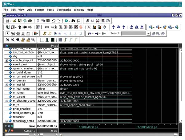
37 37


38 The class tree window also provides some useful options for viewing the class declaration and how many times the class instance has been used in the verification environment as shown in Figure 4. 38


39 Figure 5 shows a sample Class Instances window. The class graph window provides a nifty way of viewing the different classes and inheritances and how they are related to each other. The default view is organized by extended class but it can also be viewed by base class. Figure 6 shows a class graph window displaying all UVM classes compiled in the TVS ARM environment. Following is the color-code followed in the diagram. Green: Represents all AXI sequences Grey: Represents all APB sequences Red: Represents the axi_master_base_sequence. All the AXI sequences are extended from this sequence. Blue: Represents the apb_master_base_sequence. All the APB sequences are extended from this sequence. Purple: Represents the tvs_arm_generic_master_ base_sequence. Both the axi_master_base_ sequence and apb_master_base_sequence are extended from this sequence. 39

40 Figure 7 shows a class graph window highlighting one of the boundary read error sequences in the TVS environment. For AXI: FACTORY OVERRIDE The TVS ARM VIP contains both AXI and APB sequences. If we run the AXI testcase, the generic driver should be replaced by the AXI driver. This can be confirmed by using the command uvm printfactory. It will show what classes are overridden by the requested type. # Instance Overrides # # Requested Type Override Path Override Type # # tvs_arm_generic_master_driver uvm_test_top.arm_top_env.arm_envr[*].generic_master_agent[0].driver tvs_arm_axi_master_driver # tvs_arm_generic_master_monitor uvm_test_top.arm_top_env.arm_envr[*].generic_master_agent[0].monitor tvs_arm_axi_master_monitor # tvs_arm_generic_master_sequencer uvm_test_top.arm_top_env.arm_envr[*].generic_master_agent[*].sequencer tvs_arm_axi_master_sequencer # tvs_arm_generic_slave_driver uvm_test_top.arm_top_env.arm_envr[*].generic_slave_agent[*].driver tvs_arm_axi_slave_driver # tvs_arm_generic_slave_monitor uvm_test_top.arm_top_env.arm_envr[*].generic_slave_agent[*].monitor tvs_arm_axi_slave_monitor # tvs_arm_generic_slave_sequencer uvm_test_top.arm_top_env.arm_envr[*].generic_slave_agent[*].sequencer tvs_arm_axi_slave_sequencer 40
41 For APB: # Instance Overrides # # Requested Type Override Path Override Type # # tvs_arm_generic_master_driver uvm_test_top.arm_top_env.arm_envr[*].generic_master_agent[0].driver tvs_arm_apb_master_driver # tvs_arm_generic_master_monitor uvm_test_top.arm_top_env.arm_envr[*].generic_master_agent[0].monitor tvs_arm_apb_master_monitor # tvs_arm_generic_slave_driver uvm_test_top.arm_top_env.arm_envr[*].generic_slave_agent[*].driver tvs_arm_apb_slave_driver # tvs_arm_generic_slave_monitor uvm_test_top.arm_top_env.arm_envr[*].generic_slave_agent[*].monitor tvs_arm_apb_slave_monitor # tvs_arm_generic_slave_sequencer uvm_test_top.arm_top_env.arm_envr[*].generic_slave_agent[*].sequencer tvs_arm_apb_slave_sequencer RAISING OBJECTIONS By using the uvm displayobjections command, we can see any objections raised in the environment: uvm displayobjections uvm_test_top Objections output # # Domain: uvm # Component: uvm_test_top # Phase: common.run # Objection: run # The total objection count is 1x` # # Source Total # Count Count Object # # 0 1 uvm_test_top # 0 1 arm_top_env # 0 1 top_virtual_sequencer # 1 1 m_tvs_arm_apb_read_seq_test_vs # FIND INSOURCE The find insource command is useful for searching methods or variables in the UVM environment. For e.g., to search the drive_transfer method, we used: find insource drive_transfer CONCLUSION Questa UVM debug helped the TVS team channelize effort that was otherwise being unproductively spent in fixing verification environment issues towards more critical verification tasks like feature addition and coverage closure. In addition to the features highlighted in this article, Questa also offers other useful features like including breakpoints, assertion debugging and constraint debugging which combine to provide a unified and powerful debug solution. Using Questa UVM debug, TVS was able to reduce debug times on the ARM VIP development activity by as much as 35%. Insource output #../tvs_arm_apb/master/sv/tvs_arm_apb_master_driver.svh:111: drive_transfer(apb_mas_xaction); #../tvs_arm_apb/master/sv/tvs_arm_apb_master_driver.svh:145: // Task name : drive_transfer #../tvs_arm_apb/master/sv/tvs_arm_apb_master_driver.svh:150: task drive_transfer (tvs_arm_apb_master_sequence_item trans); #../tvs_arm_apb/master/sv/tvs_arm_apb_master_driver.svh:165: endtask : drive_transfer 41

42 VERIFICATION ACADEMY The Most Comprehensive Resource for Verification Training 21 Video Courses Available Covering Intelligent Testbench Automation Metrics in SoC Verification Verification Planning Introductory, Basic, and Advanced UVM Assertion-Based Verification FPGA Verification Testbench Acceleration Power Aware Verification Analog Mixed-Signal Verification UVM and Coverage Online Methodology Cookbooks Discussion Forum with more than 5000 topics UVM Connect and UVM Express Kits www. verificationacademy.com

43 Editor: Tom Fitzpatrick Program Manager: Rebecca Granquist Wilsonville Worldwide Headquarters 8005 SW Boeckman Rd. Wilsonville, OR Phone: To subscribe visit: To view our blog visit: VERIFICATIONHORIZONSBLOG.COM
Fast Track to Productivity Using Questa Verification IP by David Aerne and Ankur Jain, Verification Technologists, Mentor Graphics
 Fast Track to Productivity Using Questa Verification IP by David Aerne and Ankur Jain, Verification Technologists, Mentor Graphics ABSTRACT The challenges inherent in verifying today s complex designs
Integrate Ethernet QVIP in a Few Hours: an A-to-Z Guide by Prashant Dixit, Questa VIP Product Team, Mentor Graphics
 Integrate Ethernet QVIP in a Few Hours: an A-to-Z Guide by Prashant Dixit, Questa VIP Product Team, Mentor Graphics ABSTRACT Functional verification is critical in the development of today s complex digital
Set a longer list of transaction attributes as per protocol legality Perform the cache data/state update at end of transaction, as needed
 Cache Coherent Interface Verification IP How a Cache Controller and Generic APIs Can Make It Easier to Generate Stimulus. by Amit Kumar Jain, Questa VIP Product Team, Mentor Graphics ABSTRACT In a multi-processor
width: 10, 20 or 40-bit interface maximum number of lanes in any direction
 MIPI LLI Verification using Questa Verification IP by Vaibhav Gupta, Lead Member Technical Staff and Yogesh Chaudhary, Consulting Staff, Mentor Graphics This article describes how incorporating LLI Questa
DDR SDRAM Bus Monitoring using Mentor Verification IP by Nikhil Jain, Mentor Graphics
 DDR SDRAM Bus Monitoring using Mentor Verification IP by Nikhil Jain, Mentor Graphics This article describes how Mentor s verification IP (VIP) for various double-data rate (DDR) memory standards can act
Graph-Based IP Verification in an ARM SoC Environment by Andreas Meyer, Verification Technologist, Mentor Graphics Corporation
 Graph-Based IP Verification in an ARM SoC Environment by Andreas Meyer, Verification Technologist, Mentor Graphics Corporation The use of graph-based verification methods for block designs has been shown
NoC Generic Scoreboard VIP by François Cerisier and Mathieu Maisonneuve, Test and Verification Solutions
 NoC Generic Scoreboard VIP by François Cerisier and Mathieu Maisonneuve, Test and Verification Solutions Abstract The increase of SoC complexity with more cores, IPs and other subsystems has led SoC architects
Reuse MATLAB Functions and Simulink Models in UVM Environments with Automatic SystemVerilog DPI Component Generation
 Reuse MATLAB Functions and Simulink Models in UVM Environments with Automatic SystemVerilog DPI Component Generation by Tao Jia, HDL Verifier Development Lead, and Jack Erickson, HDL Product Marketing
Making it Easy to Deploy the UVM by Dr. Christoph Sühnel, frobas GmbH
 Making it Easy to Deploy the UVM by Dr. Christoph Sühnel, frobas GmbH Abstract The Universal Verification Methodology (UVM) is becoming the dominant approach for the verification of large digital designs.
Three Steps to Unified SoC Design and Verification by Shabtay Matalon and Mark Peryer, Mentor Graphics
 Three Steps to Unified SoC Design and Verification by Shabtay Matalon and Mark Peryer, Mentor Graphics Developing a SoC is a risky business in terms of getting it right considering the technical complexity
DO-254 Testing of High Speed FPGA Interfaces by Nir Weintroub, CEO, and Sani Jabsheh, Verisense
 DO-254 Testing of High Speed FPGA Interfaces by Nir Weintroub, CEO, and Sani Jabsheh, Verisense As the complexity of electronics for airborne applications continues to rise, an increasing number of applications
Comprehensive CDC Verification with Advanced Hierarchical Data Models
 Comprehensive CDC Verification with Advanced Hierarchical Data Models by Anwesha Choudhury, Ashish Hari, Aditya Vij, and Ping Yeung Mentor, A Siemens Business The size and complexity of designs, and the
SVA in a UVM Class-based Environment by Ben Cohen, author, consultant, and trainer
 SVA in a UVM Class-based Environment by Ben Cohen, author, consultant, and trainer INTRODUCTION Verification can be defined as the check that the design meets the requirements. How can this be achieved?
Power Up Hardware/Software Verification Productivity by Matthew Ballance, Mentor Graphics
 Power Up Hardware/Software Verification Productivity by Matthew Ballance, Mentor Graphics Today s complex designs increasingly include at least one, and often more, embedded processors. Given software
Nine Effective Features of NVMe Questa Verification IP to Help You Verify PCIe Based SSD Storage by Saurabh Sharma, Mentor Graphics
 Nine Effective Features of NVMe Questa Verification IP to Help You Verify PCIe Based SSD Storage by Saurabh Sharma, Mentor Graphics INTRODUCTION Non-Volatile Memory Express (NVMe ) is a new software interface
An Evaluation of the Advantages of Moving from a VHDL to a UVM Testbench by Shaela Rahman, Baker Hughes
 An Evaluation of the Advantages of Moving from a VHDL to a UVM Testbench by Shaela Rahman, Baker Hughes FPGA designs are becoming too large to verify by visually checking waveforms, as the functionality
Configuring Memory Read Completions Sent by PCIe QVIP
 Configuring Memory Read Completions Sent by PCIe QVIP by Arushi Jain and Rajat Rastogi Mentor, A Siemens Business PCI Express (PCIe) is a point-to-point serial transceiver interconnect that provides higher
Complex Signal Processing Verification under DO-254 Constraints by François Cerisier, AEDVICES Consulting
 Complex Signal Processing Verification under DO-254 Constraints by François Cerisier, AEDVICES Consulting Building a complex signal processing function requires a deep understanding of the signal characteristics
Automated Generation of Functional Coverage Metrics for Input Stimulus by Mike Andrews, Verification Technologist, Mentor Graphics
 Automated Generation of Functional Coverage Metrics for Input Stimulus by Mike Andrews, Verification Technologist, Mentor Graphics Questa infact intelligent testbench automation has allowed many verification
Small, Maintainable Tests
 Small, Maintainable Tests by Ashley Winn, Sondrel IC Design Services In any verification environment it takes a significant amount of work to keep all the tests running and to ensure that each test continues
Verification Planning with Questa Verification Management
 Verification Planning with Questa Verification Management by Kishan Kalavadiya and Bhavinkumar Rajubhai Patel, einfochips Verification of complex SoC (System on Chip) requires tracking of all low level
AXI4-Stream Verification IP v1.0
 AXI4-Stream Verification IP v1.0 LogiCORE IP Product Guide Vivado Design Suite Table of Contents IP Facts Chapter 1: Overview Feature Summary..................................................................
Simplified UVM for FPGA Reliability UVM for Sufficient Elemental Analysis in DO-254 Flows by Shashi Bhutada, Mentor Graphics
 Simplified UVM for FPGA Reliability UVM for Sufficient Elemental Analysis in DO-254 Flows by Shashi Bhutada, Mentor Graphics INTRODUCTION DO-254 and other safety critical applications require meticulous
Optimizing Emulator Utilization by Russ Klein, Program Director, Mentor Graphics
 Optimizing Emulator Utilization by Russ Klein, Program Director, Mentor Graphics INTRODUCTION Emulators, like Mentor Graphics Veloce, are able to run designs in RTL orders of magnitude faster than logic
Portable VHDL Testbench Automation with Intelligent Testbench Automation by Matthew Ballance, Mentor Graphics
 Portable VHDL Testbench Automation with Intelligent Testbench Automation by Matthew Ballance, Mentor Graphics We ve come a long way since digital designs were sketched as schematics by hand on paper and
Formal Verification: Not Just for Control Paths
 Formal Verification: Not Just for Control Paths by Rusty Stuber, Mentor, A Siemens Business Formal property verification is sometimes considered a niche methodology ideal for control path applications.
PowerAware RTL Verification of USB 3.0 IPs by Gayathri SN and Badrinath Ramachandra, L&T Technology Services Limited
 PowerAware RTL Verification of USB 3.0 IPs by Gayathri SN and Badrinath Ramachandra, L&T Technology Services Limited INTRODUCTION Power management is a major concern throughout the chip design flow from
Universal Verification Methodology(UVM)
") Universal Verification Methodology(UVM) A Powerful Methodology for Functional Verification of Digital Hardware Abstract - With the increasing adoption of UVM, there is a growing demand for guidelines and
Universal Verification Methodology(UVM) A Powerful Methodology for Functional Verification of Digital Hardware Abstract - With the increasing adoption of UVM, there is a growing demand for guidelines and
Boost Verification Results by Bridging the Hardware/Software Testbench Gap
 Boost Verification Results by Bridging the Hardware/Software Testbench Gap Matthew Ballance Mentor Graphics Corporation Design Verification Technology Division Wilsonville, Oregon matt_ballance@mentor.com
Slaying the UVM Reuse Dragon Issues and Strategies for Achieving UVM Reuse
 Slaying the UVM Reuse Dragon Issues and Strategies for Achieving UVM Reuse Mike Baird WHDL Willamette, OR mike@whdl.com Bob Oden UVM Field Specialist Mentor Graphics Raleigh, NC bob_oden@mentor.com Abstract
LEVERAGING A NEW PORTABLE STIMULUS APPROACH Graph or rule based stimulus descriptions
 A New Stimulus Model for CPU Instruction Sets by Staffan Berg, European Applications Engineer, and Mike Andrews, Verification Technologist, Mentor Graphics INTRODUCTION Verifying that a specific implementation
Accelerating Networking Products to Market by Lauro Rizzatti, Rizzatti LLC
 Accelerating Networking Products to Market by Lauro Rizzatti, Rizzatti LLC Take a step down the stack beyond optical networks, switches, routers and software-defined networking to consider the networking
Monitors, Monitors Everywhere Who Is Monitoring the Monitors
 Monitors, Monitors Everywhere Who Is Monitoring the Monitors Rich Edelman Mentor Graphics Raghu Ardeishar Mentor Graphics Abstract The reader of this paper should be interested in predicting the behavior
Module- or Class-Based URM? A Pragmatic Guide to Creating Verification Environments in SystemVerilog. Paradigm Works, Inc. Dr.
 Module- or Class-Based URM? A Pragmatic Guide to Creating Verification Environments in SystemVerilog Paradigm Works, Inc. Dr. Ambar Sarkar Session # 2.15 Presented at Module- or Class-Based URM? A Pragmatic
Vertical Reuse of functional verification from subsystem to SoC level (with seamless SoC emulation)
") Vertical Reuse of functional verification from subsystem to SoC level (with seamless SoC emulation) Pranav Kumar, Staff Engineer Digvijaya Pratap SINGH, Sr. Staff Engineer STMicroelectronics, Greater NOIDA,
Vertical Reuse of functional verification from subsystem to SoC level (with seamless SoC emulation) Pranav Kumar, Staff Engineer Digvijaya Pratap SINGH, Sr. Staff Engineer STMicroelectronics, Greater NOIDA,
Responding to TAT Improvement Challenge through Testbench Configurability and Re-use
 Responding to TAT Improvement Challenge through Testbench Configurability and Re-use Akhila M, Kartik Jain, Renuka Devi, Mukesh Bhartiya Accellera Systems Initiative 1 Motivation Agenda Generic AMBA based
Parameters and OVM Can t They Just Get Along?
 Parameters and OVM Can t They Just Get Along? Bryan Ramirez Xilinx, Inc. 3100 Logic Dr. Longmont, CO 80503 720-652-3561 bryan.ramirez@xilinx.com ABSTRACT Verifying a highly parameterized design under test
IMPLEMENTATION OF LOW POWER INTERFACE FOR VERIFICATION IP (VIP) OF AXI4 PROTOCOL
 OF AXI4 PROTOCOL") e-issn 2455 1392 Volume 2 Issue 8, August 2016 pp. 1 8 Scientific Journal Impact Factor : 3.468 http://www.ijcter.com IMPLEMENTATION OF LOW POWER INTERFACE FOR VERIFICATION IP (VIP) OF AXI4 PROTOCOL Bhavana
e-issn 2455 1392 Volume 2 Issue 8, August 2016 pp. 1 8 Scientific Journal Impact Factor : 3.468 http://www.ijcter.com IMPLEMENTATION OF LOW POWER INTERFACE FOR VERIFICATION IP (VIP) OF AXI4 PROTOCOL Bhavana
Design and Verification of Slave Block in Ethernet Management Interface using UVM
 Indian Journal of Science and Technology, Vol 9(5), DOI: 10.17485/ijst/2016/v9i5/87173, February 2016 ISSN (Print) : 0974-6846 ISSN (Online) : 0974-5645 Design and Verification of Slave Block in Ethernet
Analyzing and Debugging Performance Issues with Advanced ARM CoreLink System IP Components
 Analyzing and Debugging Performance Issues with Advanced ARM CoreLink System IP Components By William Orme, Strategic Marketing Manager, ARM Ltd. and Nick Heaton, Senior Solutions Architect, Cadence Finding
Figure 1: Target environment includes peripherals.
 Virtualization Delivers Total Verification of SoC Hardware, Software, and Interfaces by Jim Kenney, Marketing Director, Emulation Division, Mentor Graphics With the majority of designs today containing
Using Mentor Questa for Pre-silicon Validation of IEEE based Silicon Instruments by CJ Clark & Craig Stephan, Intellitech Corporation
 Using Mentor Questa for Pre-silicon Validation of IEEE 1149.1-2013 based Silicon Instruments by CJ Clark & Craig Stephan, Intellitech Corporation INTRODUCTION IEEE 1149.1-2013 is not your father s JTAG.
OVM to UVM Migration, or There and Back Again: A Consultant s Tale. by Mark Litterick, Verification Consultant, Verilab GmbH
 OVM to UVM Migration, or There and Back Again: A Consultant s Tale. by Mark Litterick, Verification Consultant, Verilab GmbH ABSTRACT Many companies have a goal to migrate to UVM but this must be achieved
Next Generation Verification Process for Automotive and Mobile Designs with MIPI CSI-2 SM Interface
 Thierry Berdah, Yafit Snir Next Generation Verification Process for Automotive and Mobile Designs with MIPI CSI-2 SM Interface Agenda Typical Verification Challenges of MIPI CSI-2 SM designs IP, Sub System
Tackling Verification Challenges with Interconnect Validation Tool
 Tackling Verification Challenges with Interconnect Validation Tool By Hao Wen and Jianhong Chen, Spreadtrum and Dave Huang, Cadence An interconnect, also referred to as a bus matrix or fabric, serves as
An approach to accelerate UVM based verification environment
 An approach to accelerate UVM based verification environment Sachish Dhar DWIVEDI/Ravi Prakash GUPTA Hardware Emulation and Verification Solutions ST Microelectronics Pvt Ltd Outline Challenges in SoC
Modeling Usable & Reusable Transactors in SystemVerilog Janick Bergeron, Scientist
 Modeling Usable & Reusable Transactors in SystemVerilog Janick Bergeron, Scientist Verification Group, Synopsys Inc janick@synopsys.com Transactors Definition Building blocks of verification environments
Hiding the Guts by Ray Salemi, Senior Verification Consultant, Mentor Graphics
 Hiding the Guts by Ray Salemi, Senior Verification Consultant, Mentor Graphics We verification test bench designers are happy sausage makers, merrily turning out complex and powerful verification environments.
Non-invasive Software Verification using Vista Virtual Platforms by Alex Rozenman, Vladimir Pilko, and Nilay Mitash, Mentor Graphics
 Non-invasive Software Verification using Vista Virtual Platforms by Alex Rozenman, Vladimir Pilko, and Nilay Mitash, Mentor Graphics Introduction With the SoCs now supporting Multi-Core processors, complex
Debugging Inconclusive Assertions and a Case Study
 Debugging Inconclusive Assertions and a Case Study by Jin Hou Mentor, A Siemens Business INTRODUCTION Formal assertion-based verification uses formal technologies to analyze if a design satisfies a given
An Introduction to Universal Verification Methodology
 An Introduction to Universal Verification Methodology 1 Bhaumik Vaidya 2 NayanPithadiya 1 2 Department of Electronics Engineering, Gujarat Technological University, Gandhinagar, Gujarat, India. 1 vaidya.bhaumik@gmail.com
Veloce2 the Enterprise Verification Platform. Simon Chen Emulation Business Development Director Mentor Graphics
 Veloce2 the Enterprise Verification Platform Simon Chen Emulation Business Development Director Mentor Graphics Agenda Emulation Use Modes Veloce Overview ARM case study Conclusion 2 Veloce Emulation Use
Accelerating RTL Simulation Techniques by Lior Grinzaig, Verification Engineer, Marvell Semiconductor Ltd.
 Accelerating RTL Simulation Techniques by Lior Grinzaig, Verification Engineer, Marvell Semiconductor Ltd. Long simulation run times are a bottleneck in the verification process. A lengthy delay between
DEVELOPMENT AND VERIFICATION OF AHB2APB BRIDGE PROTOCOL USING UVM TECHNIQUE
 DEVELOPMENT AND VERIFICATION OF AHB2APB BRIDGE PROTOCOL USING UVM TECHNIQUE N.G.N.PRASAD Assistant Professor K.I.E.T College, Korangi Abstract: The AMBA AHB is for high-performance, high clock frequency
UVM BASED TEST BENCH TO VERIFY AMBA AXI4 SLAVE PROTOCOL
 UVM BASED TEST BENCH TO VERIFY AMBA AXI4 SLAVE PROTOCOL Smitha A P1, Ashwini S2 1 M.Tech VLSI Design and Embedded Systems, ECE Dept. 2 Assistant Professor, ECE Dept. NCET, Bengaluru, India. ---------------------------------------------------------------------***---------------------------------------------------------------------
PCIe Verification in a SystemC environment using the Cadence VIP
 PCIe Verification in a SystemC environment using the Cadence VIP 25 / 04 / 2014 Maarten de Vries Verification team leader 1 SUMMARY BULL : Asic development for HPC BULL s next chip will use PCIexpress
FPGA chip verification using UVM
 FPGA chip verification using UVM Ravi Ram Principal Verification Engineer Altera Corp Charles Zhang Verification Architect Paradigm Works Outline Overview - Verilog based verification environment - Why
AN INTRODUCTION TO UNIT TESTING
 Unit Testing Your Way to a Reliable Testbench by Neil Johnson, Principal Consultant, XtremeEDA, and Mark Glasser, Principal Engineer, Verification Architect, NVIDIA AN INTRODUCTION TO UNIT TESTING Writing
It s Surprising What the Boy Scouts Can Teach Us about Verification. By Tom Fitzpatrick, Editor and Verification Technologist
 A PUBLICATION OF MENTOR GRAPHICS VOLUME 9, ISSUE 3 OCT 2013 WHAT S ON THE HORIZON? Software-Driven Testing of AXI Bus in a Dual Core ARM System Using Questa to check everything from protocol compliance
Simulation-Based FlexRay TM Conformance Testing an OVM success story
 Simulation-Based FlexRay TM Conformance Testing an OVM success story Mark Litterick, Co-founder & Verification Consultant, Verilab Abstract This article presents a case study on how the Open Verification
Verification of Clock Domain Crossing Jitter and Metastability Tolerance using Emulation
 Verification of Clock Domain Crossing Jitter and Metastability Tolerance using Emulation Ashish Hari ashish_hari@mentor.com Suresh Krishnamurthy k_suresh@mentor.com Amit Jain amit_jain@mentor.com Yogesh
A New Class Of Registers
 A New Class Of s M. Peryer Mentor Graphics (UK) Ltd., Rivergate, London Road, Newbury, Berkshire, RG14 2QB, United Kingdom D. Aerne Mentor Graphics Corp., 8005 SW Boeckman Road, Wilsonville, OR USA 97070-7777
Functional Coverage Development Tips: Do s and Don ts by Samrat Patel, ASIC Verification Engineer, and Vipul Patel, ASIC Engineer, einfochips
 Functional Coverage Development Tips: Do s and Don ts by Samrat Patel, ASIC Verification Engineer, and Vipul Patel, ASIC Engineer, einfochips INTRODUCTION A verification engineer s fundamental goal is
CSE Verification Plan
 CSE 45493-3 Verification Plan 1 Verification Plan This is the specification for the verification effort. It indicates what we are verifying and how we are going to do it! 2 Role of the Verification Plan
Hardware/Software Co-Verification Using the SystemVerilog DPI
 Hardware/Software Co-Verification Using the SystemVerilog DPI Arthur Freitas Hyperstone GmbH Konstanz, Germany afreitas@hyperstone.com Abstract During the design and verification of the Hyperstone S5 flash
Will Everything Start To Look Like An SoC?
 Will Everything Start To Look Like An SoC? Vikas Gautam, Synopsys Verification Futures Conference 2013 Bangalore, India March 2013 Synopsys 2012 1 SystemVerilog Inherits the Earth e erm SV urm AVM 1.0/2.0/3.0
Four Best Practices for Prototyping MATLAB and Simulink Algorithms on FPGAs by Stephan van Beek, Sudhir Sharma, and Sudeepa Prakash, MathWorks
 Four Best Practices for Prototyping MATLAB and Simulink Algorithms on FPGAs by Stephan van Beek, Sudhir Sharma, and Sudeepa Prakash, MathWorks Chip design and verification engineers often write as many
PA GLS: The Power Aware Gate-level Simulation
 PA GLS: The Power Aware Gate-level Simulation by Progyna Khondkar Mentor, A Siemens Business In post-synthesis, gate-level netlist (GL-netlist), power aware (PA) simulation, the fundamental focus is to
e-issn: p-issn:
 Available online at www.ijiere.com International Journal of Innovative and Emerging Research in Engineering e-issn: 2394-3343 p-issn: 2394-5494 PCIe CHECKER LIBRARY GENERATION OF SEQUENCES & DRIVER COMPONENT
Verification Prowess with the UVM Harness
 Verification Prowess with the UVM Harness Interface Techniques for Advanced Verification Strategies Jeff Vance, Jeff Montesano Verilab Inc. October 19, 2017 Austin SNUG 2017 1 Agenda Introduction UVM Harness
Test and Verification Solutions. ARM Based SOC Design and Verification
 Test and Verification Solutions ARM Based SOC Design and Verification 7 July 2008 1 7 July 2008 14 March 2 Agenda System Verification Challenges ARM SoC DV Methodology ARM SoC Test bench Construction Conclusion
Modeling Performance Use Cases with Traffic Profiles Over ARM AMBA Interfaces
 Modeling Performance Use Cases with Traffic Profiles Over ARM AMBA Interfaces Li Chen, Staff AE Cadence China Agenda Performance Challenges Current Approaches Traffic Profiles Intro Traffic Profiles Implementation
Open Verification Methodology (OVM)
") Open Verification Methodology (OVM) Built on the success of the Advanced Verification Methodology (AVM) from Mentor Graphics and the Universal Reuse Methodology (URM) from Cadence, the OVM brings the combined
Open Verification Methodology (OVM) Built on the success of the Advanced Verification Methodology (AVM) from Mentor Graphics and the Universal Reuse Methodology (URM) from Cadence, the OVM brings the combined
Bring IP verification closer to SoC
 Bring IP verification closer to SoC Scalable Methods to Bridge the Gap between IP and SoC Verification Gaurav Gupta, Tejbal Prasad, Rohit Goyal, Sachin Jain, Vipin verma Automative Industrial Solutions
Title: Using Test-IP Based Verification Techniques in a UVM Environment
 Title: Using Test-IP Based Verification Techniques in a UVM Environment Vidya Bellippady Sundar Haran Jay O Donnell Microsemi Corporation Microsemi Corporation Mentor Graphics San Jose, CA Hyderabad, India
SPECMAN-E TESTBENCH. Al. GROSU 1 M. CARP 2
 Bulletin of the Transilvania University of Braşov Vol. 11 (60) No. 1-2018 Series I: Engineering Sciences SPECMAN-E TESTBENCH Al. GROSU 1 M. CARP 2 Abstract: The scope of this document is to present a Verification
Will Everything Start To Look Like An SoC?
 Will Everything Start To Look Like An SoC? Janick Bergeron, Synopsys Verification Futures Conference 2012 France, Germany, UK November 2012 Synopsys 2012 1 SystemVerilog Inherits the Earth e erm SV urm
Software Driven Verification at SoC Level. Perspec System Verifier Overview
 Software Driven Verification at SoC Level Perspec System Verifier Overview June 2015 IP to SoC hardware/software integration and verification flows Cadence methodology and focus Applications (Basic to
Development of UVM based Reusabe Verification Environment for SHA-3 Cryptographic Core
 Development of UVM based Reusabe Verification Environment for SHA-3 Cryptographic Core M. N. Kubavat Dept. of VLSI & Embedded Systems Design, GTU PG School Gujarat Technological University Ahmedabad, India
Designing Procedural-Based Behavioral Bus Functional Models for High Performance Verification
 Designing Procedural-Based Behavioral Bus Functional Models for High Performance Verification Gregg D. Lahti gregg.d.lahti@intel.com Tim L. Wilson tim.l.wilson@intel.com Intel Corporation ABSTRACT Testing
Verification of Digital Systems, Spring UVM Basics
 1 UVM Basics Nagesh Loke ARM Cortex-A Class CPU Verification Lead 1 What to expect This lecture aims to: demonstrate the need for a verification methodology provide an understanding of some of the key
Assertion Based Verification of AMBA-AHB Using System Verilog
 Assertion Based Verification of AMBA-AHB Using System Verilog N.Karthik M.Tech VLSI, CMR Institute of Technology, Kandlakoya Village, Medchal Road, Hyderabad, Telangana 501401. M.Gurunadha Babu Professor
Leveraging Formal Verification Throughout the Entire Design Cycle
 Leveraging Formal Verification Throughout the Entire Design Cycle Verification Futures Page 1 2012, Jasper Design Automation Objectives for This Presentation Highlight several areas where formal verification
Assertions Instead of FSMs/logic for Scoreboarding and Verification by Ben Cohen, Accellera Systems Initiative, VhdlCohen Publishing
 Assertions Instead of FSMs/logic for Scoreboarding and Verification by Ben Cohen, Accellera Systems Initiative, VhdlCohen Publishing Monitors, scoreboards, and verification logic are typically implemented
VERIFICATION OF AHB PROTOCOL USING SYSTEM VERILOG ASSERTIONS
 VERIFICATION OF AHB PROTOCOL USING SYSTEM VERILOG ASSERTIONS Nikhil B. Gaikwad 1, Vijay N. Patil 2 1 P.G. Student, Electronics & Telecommunication Department, Pimpri Chinchwad College of Engineering, Pune,
SVA Alternative for Complex Assertions
 SVA Alternative for Complex Assertions by Ben Cohen, VHDL Cohen Publishing Assertion-based verification has been an integral part of modern-day design verification. Concurrent SVA is a powerful assertion
Artifacts of Custom Checkers in Questa Power Aware Dynamic Simulation
 Artifacts of Custom Checkers in Questa Power Aware Dynamic Simulation by Progyna Khondkar, Mentor Graphics INTRODUCTION The Questa Power Aware (PA) dynamic simulator (PA-SIM) provides a wide range of automated
BEYOND UVM REGISTERS BETTER, FASTER, SMARTER RICH EDELMAN AND BHUSHAN SAFI, MENTOR GRAPHICS
 BEYOND UVM REGISTERS BETTER, FASTER, SMARTER RICH EDELMAN AND BHUSHAN SAFI, MENTOR GRAPHICS F U N C T I O N A L V E R I F I C A T I O N W H I T E P A P E R w w w. m e n t o r. c o m INTRODUCTION The UVM
Shortest path to the lab. Real-world verification. Probes provide observability
 OVM/UVM for FPGAs: The End of Burn and Churn FPGA Verification by In-Circuit Test Burn and churn based on at-speed test with real input 2 Shortest path to the lab Nominal simulation of RTL blocks Relatively
Configuring a Date with a Model
 Configuring a Date with a Model A Guide to Configuration Objects and Register Models Jeff Montesano, Jeff Vance Verilab, Inc. copyright (c) 2016 Verilab & SNUG September 29, 2016 SNUG Austin SNUG 2016
INDUSTRIAL TRAINING: 6 MONTHS PROGRAM TEVATRON TECHNOLOGIES PVT LTD
 6 Month Industrial Internship in VLSI Design & Verification" with Industry Level Projects. CURRICULUM Key features of VLSI-Design + Verification Module: ASIC & FPGA design Methodology Training and Internship
Efficient Failure Triage with Automated Debug: a Case Study by Sean Safarpour, Evean Qin, and Mustafa Abbas, Vennsa Technologies Inc.
 Efficient Failure Triage with Automated Debug: a Case Study by Sean Safarpour, Evean Qin, and Mustafa Abbas, Vennsa Technologies Inc. Functional debug is a dreadful yet necessary part of today s verification
S2C K7 Prodigy Logic Module Series
 S2C K7 Prodigy Logic Module Series Low-Cost Fifth Generation Rapid FPGA-based Prototyping Hardware The S2C K7 Prodigy Logic Module is equipped with one Xilinx Kintex-7 XC7K410T or XC7K325T FPGA device
Comprehensive AMS Verification using Octave, Real Number Modelling and UVM
 Comprehensive AMS Verification using Octave, Real Number Modelling and UVM John McGrath, Xilinx, Cork, Ireland (john.mcgrath@xilinx.com) Patrick Lynch, Xilinx, Dublin, Ireland (patrick.lynch@xilinx.com)
DESIGN AND VERIFICATION ANALYSIS OF APB3 PROTOCOL WITH COVERAGE
 DESIGN AND VERIFICATION ANALYSIS OF APB3 PROTOCOL WITH COVERAGE Akhilesh Kumar and Richa Sinha Department of E&C Engineering, NIT Jamshedpur, Jharkhand, India ABSTRACT Today in the era of modern technology
Graph-Based Verification in a UVM Environment
 Graph-Based Verification in a UVM Environment Staffan Berg European Applications Engineer July 2012 Graph-Based Intelligent Testbench Automation (itba) Welcome DVClub Attendees Organizers Presenters Verification
UVM hardware assisted acceleration with FPGA co-emulation
 UVM hardware assisted acceleration with FPGA co-emulation Alex Grove, Aldec Inc. Accellera Systems Initiative 1 Tutorial Objectives Discuss use of FPGAs for functional verification, and explain how to
Efficient Verification of Mixed-Signal SerDes IP Using UVM
 Efficient Verification of Mixed-Signal SerDes IP Using UVM Varun R, Senior Design Engineer, Cadence Vinayak Hegde, Design Engineering Manager, Cadence IP are an integral part of systems-on-chips (SoC)
Sunburst Design - SystemVerilog UVM Verification Training by Recognized Verilog & SystemVerilog Guru, Cliff Cummings of Sunburst Design, Inc.
 World Class SystemVerilog & UVM Training Sunburst Design - SystemVerilog UVM Verification Training by Recognized Verilog & SystemVerilog Guru, Cliff Cummings of Sunburst Design, Inc. Cliff Cummings is
VERIFICATION OF AMBA AXI BUS PROTOCOL IMPLEMENTING INCR AND WRAP BURST USING SYSTEM VERILOG
 VERIFICATION OF AMBA AXI BUS PROTOCOL IMPLEMENTING INCR AND WRAP BURST USING SYSTEM VERILOG Harsha Garua 1, Keshav Sharma 2, Chusen Duari 3 1 Manipal University Jaipur 2 Manipal University Jaipur 3 Assistant