SoMachine V3.0. Modbus TCP Communications Modbus_TCP.project Example Guide. 04/2011 Basic. Intermediate Expert.
|
|
|
- Joleen Welch
- 5 years ago
- Views:
Transcription
1 SoMachine V3.0 Modbus TCP Communications Modbus_TCP.project Example Guide 04/2011 Basic Intermediate Expert EIO
2 The information provided in this documentation contains general descriptions and/or technical characteristics of the performance of the products contained herein. This documentation is not intended as a substitute for and is not to be used for determining suitability or reliability of these products for specific user applications. It is the duty of any such user or integrator to perform the appropriate and complete risk analysis, evaluation and testing of the products with respect to the relevant specific application or use thereof. Neither Schneider Electric nor any of its affiliates or subsidiaries shall be responsible or liable for misuse of the information contained herein. If you have any suggestions for improvements or amendments or have found errors in this publication, please notify us. No part of this document may be reproduced in any form or by any means, electronic or mechanical, including photocopying, without express written permission of Schneider Electric. All pertinent state, regional, and local safety regulations must be observed when installing and using this product. For reasons of safety and to help ensure compliance with documented system data, only the manufacturer should perform repairs to components. When devices are used for applications with technical safety requirements, the relevant instructions must be followed. Failure to use Schneider Electric software or approved software with our hardware products may result in injury, harm, or improper operating results. Failure to observe this information can result in injury or equipment damage Schneider Electric. All rights reserved. 2 EIO /2011
3 Table of Contents SAFETY INFORMATION 5 ABOUT THE BOOK 7 1. DESCRIPTION Presentation Main Features Functional Analysis of the Example Functions Used in this Example Hardware Installation DESCRIPTION OF THE EXAMPLE S CONTENT CREATION OF THE PROJECT IP ADDRESS CONFIGURATION LIBRARY MANAGER ST, LD, OR CFC PROGRAM ST Programs ST Program of the ATV-IMC Controller ST Program of the M258 Controller LD Programs LD Program of the ATV-IMC Controller LD Program of the M258 Controller CFC Programs CFC Program of the ATV-IMC Controller CFC Program of the M258 Controller RUNNING THE EXAMPLE MAST Task Configuration MAST Task of the ATV-IMC Controller MAST Task of the M258 Controller Downloading the Example to the Controllers Downloading the Example to the ATV-IMC Controller Connecting the ATV-IMC Controller to the Ethernet Network Downloading the Example to the M258 Controller Connecting the M258 Controller to the Ethernet Network Running the Example on the ATV-IMC and M258 Controllers 84 EIO /2011 3
4 4 EIO /2011

5 Safety Information Safety Information Important Information NOTICE Read these instructions carefully, and look at the equipment to become familiar with the device before trying to install, operate, or maintain it. The following special messages may appear throughout this documentation or on the equipment to warn of potential hazards or to call attention to information that clarifies or simplifies a procedure. The addition of this symbol to a Danger or Warning safety label indicates that an electrical hazard exists, which will result in personal injury if the instructions are not followed. This is the safety alert symbol. It is used to alert you to potential personal injury hazards. Obey all safety messages that follow this symbol to avoid possible injury or death. DANGER DANGER indicates an imminently hazardous situation which, if not avoided, will result in death or serious injury. WARNING WARNING indicates a potentially hazardous situation which, if not avoided, can result in death or serious injury. CAUTION CAUTION indicates a potentially hazardous situation which, if not avoided, can result in minor or moderate injury. CAUTION CAUTION, used without the safety alert symbol, indicates a potentially hazardous situation which, if not avoided, can result in equipment damage. PLEASE NOTE Electrical equipment should be installed, operated, serviced, and maintained only by qualified personnel. No responsibility is assumed by Schneider Electric for any consequences arising out of the use of this material. A qualified person is one who has skills and knowledge related to the construction and operation of electrical equipment and the installation, and has received safety training to recognize and avoid the hazards involved. EIO /2011 5
6 Safety Information 6 EIO /2011

7 About the Book About the Book At a Glance Document Scope This document describes one of the SoMachine examples. Since the example described in this document is intended for learning purposes only, it must not be run, nor tested, on products that are part of a machine or process. Validity Note Step Action This document has been updated with the release of SoMachine V3.0. The technical characteristics of the device(s) described in this manual also appear online. To access this information online: 1 Go to 2 In the Search box on the home page, type a model number. Do not type any blank spaces in the model number. To get information on a grouping of similar modules, you can use the characters **; do not use dots or xx's. 3 Under All, click Products Product Datasheets and select the model number that interests you. 4 To save or print a data sheet as a.pdf file, click Export to PDF. The characteristics presented in this manual should be the same as those that appear online. In line with our policy of constant improvement we may revise content over time to improve clarity and accuracy. In the event that you see a difference between the manual and online information, use the online information as your reference. Related Documents Title of Documentation Modicon M258 Logic Controller Hardware Guide Reference Number EIO (ENG); EIO (FRE); EIO (GER); EIO (SPA); EIO (ITA); EIO (CHS) EIO /2011 7
8 About the Book Title of Documentation Modicon M258 Logic Controller Programming Guide Modicon M258 Logic Controller System Functions and Variables M258 PLCSystem Library Guide Altivar ATV-IMC Drive Controller VW3A3521S0 Hardware Guide ATV IMC Drive Controller Programming Guide ATV IMC Drive Controller System Functions and Variables ATV-IMC PLCSystem Library Guide Altivar 71 Variable speed drives for synchronous motors and asynchronous motors Installation Manual Altivar 71 Variable speed drives for synchronous and asynchronous motors Programming manual SoMachine Modbus and ASCII Read/Write Functions PLCCommunication Library Guide Reference Number EIO (ENG); EIO (FRE); EIO (GER); EIO (SPA); EIO (ITA); EIO (CHS) EIO (ENG); EIO (FRE); EIO (GER); EIO (SPA); EIO (ITA); EIO (CHS) S1A10252 (ENG); S1A34915 (FRE); S1A34916 (GER); S1A34917 (ITA); S1A34918 (SPA); S1A34919 (CHS) EIO (ENG); EIO (FRE); EIO (GER); EIO (ITA); EIO (SPA); EIO (CHS) EIO (ENG); EIO (FRE); EIO (GER); EIO (SPA); EIO (ITA); EIO (CHS) (ENG); (FRE); (GER); (SPA); (ITA); (CHS) (ENG); (FRE); (GER); (SPA); (ITA); (CHS) EIO (ENG); EIO (FRE); EIO (GER); EIO (ITA); EIO (SPA); EIO (CHS) 8 EIO /2011
9 About the Book Product Related Information This document and its related SoMachine project file focus on specific Functions and Function Blocks of the Schneider libraries provided with SoMachine, and on specific features available in SoMachine if these features are related to these libraries. They are intended to help you developing, testing, commissioning, and integrating applicative software of your own design on control systems. It is intended for new SoMachine users who already have some degree of expertise in the design and programming of control systems. UNINTENDED EQUIPMENT OPERATION WARNING Only use software approved by Schneider Electric for use with this equipment. Update your application program every time you change the physical hardware configuration. Failure to follow these instructions can result in death, serious injury, or equipment damage. LOSS OF CONTROL WARNING The designer of any control scheme must consider the potential failure modes of control paths and, for certain critical control functions, provide a means to achieve a safe state during and after a path failure. Examples of critical control functions are emergency stop and overtravel stop, power outage and restart. Separate or redundant control paths must be provided for critical control functions. System control paths may include communication links. Consideration must be given to the implications of unanticipated transmission delays or failures of the link. Observe all accident prevention regulations and local safety guidelines. 1 Each implementation of this equipment must be individually and thoroughly tested for proper operation before being placed into service. Failure to follow these instructions can result in death, serious injury, or equipment damage. 1 For additional information, refer to NEMA ICS 1.1 (latest edition), "Safety Guidelines for the Application, Installation, and Maintenance of Solid State Control" and to NEMA ICS 7.1 (latest edition), "Safety Standards for Construction and Guide for Selection, Installation and Operation of Adjustable-Speed Drive Systems" or their equivalent governing your particular location. Before You Begin The products specified in this document have been tested under actual service conditions. Of course, your specific application requirements may be different from those assumed for this and any related examples described herein. In that case, you will have to adapt the information provided in this and other related documents to your particular needs. To do so, you will need to consult the specific product EIO /2011 9
10 About the Book documentation of the hardware and/or software components that you may add or substitute for any examples specified in this documentation. Pay particular attention and conform to any safety information, different electrical requirements and normative standards that would apply to your adaptation. WARNING REGULATORY INCOMPATIBILITY Be sure that all equipment applied and systems designed comply with all applicable local, regional and national regulations and standards. Failure to follow these instructions can result in death, serious injury, or equipment damage. The use and application of the information contained herein require expertise in the design and programming of automated control systems. Only the user or integrator can be aware of all the conditions and factors present during installation and setup, operation, and maintenance of the machine or process, and can therefore determine the automation and associated equipment and the related safeties and interlocks which can be effectively and properly used. When selecting automation and control equipment, and any other related equipment or software, for a particular application, the user or integrator must also consider any applicable local, regional or national standards and/or regulations. Some of the major software functions and/or hardware components used in the proposed architectures and examples described in this document cannot be substituted without significantly compromising the performance of your application. Further, any such substitutions or alterations may completely invalidate any proposed architectures, descriptions, examples, instructions, wiring diagrams and/or compatibilities between the various hardware components and software functions specified herein and in related documentation. You must be aware of the consequences of any modifications, additions or substitutions. A residual risk, as defined by EN/ISO , Article 5, will remain if: it is necessary to modify the recommended logic and if the added or modified components are not properly integrated in the control circuit. you do not follow the required standards applicable to the operation of the machine, or if the adjustments to and the maintenance of the machine are not properly made (it is essential to strictly follow the prescribed machine maintenance schedule). the devices connected to any safety outputs do not have mechanically-linked contacts. CAUTION EQUIPMENT INCOMPATIBILITY Read and thoroughly understand all device and software documentation before attempting any component substitutions or other changes related to the application examples provided in this document. Failure to follow these instructions can result in injury or equipment damage. 10 EIO /2011
11 About the Book Start-up and Test Before using electrical control and automation equipment after design and installation, the application and associated functional safety system must be subjected to a start-up test by qualified personnel to verify correct operation of the equipment. It is important that arrangements for such testing be made and that enough time is allowed to perform complete and satisfactory testing. EQUIPMENT OPERATION HAZARD CAUTION Verify that all installation and set up procedures have been completed. Before operational tests are performed, remove all blocks or other temporary holding means used for shipment from all component devices. Remove tools, meters and debris from equipment. Failure to follow these instructions can result in injury or equipment damage. Verify that the completed system, including the functional safety system, is free from all short circuits and grounds, except those grounds installed according to local regulations. If high-potential voltage testing is necessary, follow the recommendations in equipment documentation to help prevent injury or equipment damage. Operation and Adjustments Regardless of the care exercised in the design and manufacture of equipment or in the selection and ratings of components, there are hazards that can be encountered if such equipment is improperly installed and operated. In some applications, such as packaging machinery, additional operator protection such as point-of-operation guarding must be provided. This is necessary if the hands and other parts of the body are free to enter the pinch points or other hazardous areas where serious injury can occur. Software products alone cannot protect an operator from injury. For this reason, the software cannot be substituted for or take the place of point-of-operation protection. WARNING UNGUARDED MACHINERY CAN CAUSE SERIOUS INJURY Do not use this software and related automation equipment on equipment which does not have point-of-operation protection. Do not reach into machinery during operation. Failure to follow these instructions can result in death, serious injury, or equipment damage. EIO /
12 About the Book Ensure that appropriate safeties and mechanical/electrical interlocks related to point-of-operation protection have been installed and are operational before placing the equipment into service. All interlocks and safeties related to point-of-operation protection must be coordinated with the related automation equipment and software programming. NOTE: Coordination of safeties and mechanical/electrical interlocks for point-ofoperation protection is outside the scope of the examples and implementations suggested herein. It is sometimes possible to adjust the equipment incorrectly and this produce unsatisfactory or unsafe operation. Always use the manufacturer instructions as a guide to functional adjustments. Personnel who have access to these adjustments must be familiar with the equipment manufacturer instructions and the machinery used with the electrical equipment. Only those operational adjustments actually required by the machine operator should be accessible to the operator. Access to other controls should be restricted to help prevent unauthorized changes in operating characteristics. User Comments We welcome your comments about this document. You can reach us by at techcomm@schneider-electric.com. 12 EIO /2011


13 1. Description 1. Description 1.1. Presentation This example presents Modbus TCP communications between a Modbus client and a Modbus server on an Ethernet network. It uses the Modbus functions available in the PLCCommunication library to show how to address a Modbus TCP device. In this example, these communications are performed between a M258 logic controller (the Modbus client) and an ATV-IMC drive controller (the Modbus server). Both controllers programs are created using SoMachine software. In this example, the purpose of these communications consists in reading and writing the value of a counter on the ATV-IMC, and exchanging the statuses of both controllers. Related SoMachine project: Modbus_TCP.project Supported SoMachine Languages: CFC IL ST FBD LD SFC Key features: Modbus TCP communications for reading and writing data on a Modbus server Requirements: To use this example, the user must have: installed SoMachine V3.0 on a PC; run at least one Basic SoMachine example. PC with SoMachine Download & Monitoring Modbus TCP protocol Ethernet network Altivar 71 drive + ATV-IMC controller M258 logic controller Note: Because it is required to run the communication functions used in this example s programs on both controllers, do not run this example in SIMULATION mode. EIO /
14 1. Description 1.2. Main Features The main features of this example include: Configuration of the Ethernet addresses of both ATV-IMC and M258 controllers using SoMachine. Addressing a Modbus server (the ATV-IMC controller) using the PLCCommunication library on a Modbus client (the M258 controller). Note: The ATV-IMC controller cannot be a Modbus client; i.e. it can only answer to Modbus TCP requests issued by a Modbus client. M258 controller: Continuous read requests of an applicative counter of the ATV- IMC controller (at %MW100) using the Modbus function #3 (Read Holding Registers). M258 controller: Continuous write requests of a copy of this applicative counter to the ATV-IMC controller (at %MW101) using the Modbus function #6 (Write Single Register). M258 controller: Periodic write request for transmitting 3 system status variables of the M258 controller (starting at %MW60008) to the ATV-IMC controller (starting at %MW200) using the Modbus function #16 (Write Multiple Registers). M258 controller: Periodic read request for reading 3 system status variables of the ATV-IMC controller (starting at %MW300) using the Modbus function #3 (Read Holding Registers). Note: The system variables of the ATV-IMC controller (starting at %MW60000) are not accessible via Modbus TCP read requests; because of this, this example reads copies of these system variables. Use example of the data read and written by the M258 controller on the ATV-IMC controller. 14 EIO /2011
15 1. Description 1.3. Functional Analysis of the Example The program described in this example, whatever its programming language, performs the following treatments: Formatting the Modbus TCP address of the ATV-IMC controller: M258 ATV-IMC Reading/writing an applicative counter: M258 ATV-IMC EIO /
16 1. Description Reading/writing system data: M258 ATV-IMC In these diagrams, the green boxes indicate where the functions of the PLCCommunication library are used. 16 EIO /2011
17 1. Description 1.4. Functions Used in this Example The Functions (and Function Blocks) used in this example are listed below, grouped by library: PLCCommunication library (Schneider Electric) Function Description Location in the Input Assistant ADDM READ_VAR SINGLE_WRITE WRITE_VAR Convert a string into an address Reads data from a Modbus device Write a single register to a Modbus device Write data to a Modbus device Function Blocks { } SEN Standard library (System) Function Description Location in the Input Assistant CONCAT Do a concatenation (combination) of two strings Module Calls { } Standard String Functions F_TRIG Detect a falling edge Function Blocks { } Standard Trigger Util library (System) Function Description Location in the Input Assistant BLINK Generate a pulsating signal Function Blocks { } Util Signals EIO /

18 1. Description Please refer to the SoMachine online help. Note: In the rest of this document, the former sentence instructs you to refer to the online help of SoMachine, accessible through its upper-right help button. Please refer to the SoMachine online help for detailed information on these Functions and Function Blocks: Function description, Graphical representation, I/O Variables description, and more. To install these libraries in your own project, please refer to Library Manager (see page 28). 18 EIO /2011
19 1. Description 1.5. Hardware Installation Required Devices 7 Ethernet network Ethernet Hub (or Switch) USB 1 Ethernet 5 2a or 2b Pgr Port 3 M258 controller 4 Ethernet 6 mini USB ATV-IMC controller Ethernet N Designation Reference Use or Description 1 SoMachine Software MSD CHNLMUA SoMachine Software, 1-station license, installed on a PC 2a SoMachine Solution Extension Software Terminal port/usb port cordset MSD CHLLMUV30S0 TCS XCN AM UM3P SoMachine Solution Extension Software, 1-station license, installed on the same PC than SoMachine Software From the mini-b USB port of the Modicon M258 controller (or from the mini-b USB port of the ATV-IMC controller) to the type A USB port on the PC terminal for programming the controller; length: 3 m (10 ft) 2b Programming cable BMX XCA USB H018 Same as TCS XCN AM UM3P, but with two ground connections along the cable; length: 1.8 m (6 ft) 3 M258 controller TM258 Compact base logic controller 4 ATV-IMC controller VW3A3521S0 Altivar ATV-IMC drive controller Altivar 71 variable speed drive ATV71 Variable speed drive on which the ATV-IMC controller is installed. Note: In this example, this variable speed drive is only optional since the ATV-IMC controller can be used as a stand-alone controller if an external 24VDC power supply is used to power it on. 5 Twisted pair hub 499 NEH Ethernet hub with 4 100BASE-TX copper ports (RJ45 shielded connectors) 6 Straight cables 490 NTW 000 Straight Ethernet cables with 2 RJ45 connectors for connection to terminal equipment (DTE); length: 2 m, 5 m, 12 m, 40 m, or 80 m 7 Crossed cable 490 NTC 000 Crossed Ethernet cable with 2 RJ45 connectors for connection between hubs, switches and transceivers; length: 5 m, 15 m, 40 m, or 80 m Please refer to the Modicon M258 Logic Controller Hardware Guide and to the Altivar ATV-IMC Drive Controller VW3A3521S0 Hardware Guide for the hardware setup of these devices. EIO /
20 2. Description of the Example s Content 2. Description of the Example s Content In SoMachine, the example is split into two applications, one for each controller: The ATV-IMC application is run on the ATV_IMC_Controller controller; its configuration is made with the following device: 1 Drive Controller: ATV-IMC S Type The Application program of this ATV-IMC controller is made of the following items: Library Manager: List of the libraries linked to the programs of this example. ST program: Contains the source code for implementing what is described for the ATV-IMC in Functional Analysis of the Example (see page 15). This is the default program since it is called by the MAST task of the controller. LD program: Translation of the ST program into LD language. To run this program on the controller, instead of the ST program, change the POU called by the MAST task of the controller from PLC_PRG_ATVIMC_ST to PLC_PRG_ATVIMC_LD. CFC program: Translation of the ST program into CFC language. To run this program on the controller, instead of the ST program, change the POU called by the MAST task of the controller from PLC_PRG_ATVIMC_ST to PLC_PRG_ATVIMC_CFC. Task Configuration: The standard MAST task, cyclically called every 10ms. Ethernet: Configuration of the IP address of the ATV-IMC controller. The M258 application is run on the M258_Controller controller; its configuration is made with the following device: 1 Logic Controller: TM258LF42DT4L The Application program of this M258 controller is made of the following items: Library Manager: List of the libraries linked to the programs of this example. ST program: Contains the source code for implementing what is described for the M258 in Functional Analysis of the Example (see page 15). This is the default program since it is called by the MAST task of the controller. LD program: Translation of the ST program into LD language. To run this program on the controller, instead of the ST program, change the POU called by the MAST task of the controller from PLC_PRG_M258_ST to PLC_PRG_M258_LD. CFC program: Translation of the ST program into CFC language. To run this program on the controller, instead of the ST program, change the POU called by the MAST task of the controller from PLC_PRG_M258_ST to PLC_PRG_M258_CFC. Task Configuration: The standard MAST task, cyclically called every 20ms. Ethernet: Configuration of the IP address of the M258 controller. 20 EIO /2011
21 2. Description of the Example s Content Example s content, visible in the Devices panel of the Program tab: EIO /

22 3. Creation of the Project 3. Creation of the Project Step Action The steps listed in the following table describe how to create the SoMachine project, including the device(s) used in this example. No details are given here since it is assumed that you already know the Basic commands of SoMachine. 1 In the Create new machine part of the Home tab, select Start with empty project to create a new SoMachine project. Give this new project the following name: Modbus_TCP. 2 In the Configuration tab, add a TM258LF42DT4L Logic Controller. Note: Details on the selected controller are displayed in the Information section of SoMachine. SoMachine controller version: Defines the version of the selected controller; it is displayed in the Information section of SoMachine. Target controller firmware version: Defines the firmware version of your controller. This version is shown when you select your controller s node, as shown as in Downloading the Example to the M258 Controller (see page 76). For compatibility purposes between a SoMachine controller version and a target controller firmware version, only the first three numbers of a version must be identical. In the preceding picture, the SoMachine controller version is compatible with any target controller firmware version. For each controller model, SoMachine only presents the latest available version. If you check the Display all versions (for expert only) option, SoMachine will list supported controller firmware versions. However, a good practice consists in using the latest available version and updating the firmware of your controller, if required. Please refer to the Modicon M258 Controller Programming Guide. 22 EIO /2011


23 3. Creation of the Project Step Action 3 Rename this controller to M258_Controller. 4 In the Configuration tab, add an ATV-IMC S Type Drive Controller. Note: Considerations on SoMachine controller versions and target controller firmware versions (see page 22) also apply to the ATV-IMC S Type controller. For details on how to update the firmware of your ATV-IMC S Type controller, please refer to the ATV IMC Drive Controller Programming Guide. EIO /

24 3. Creation of the Project Step Action 5 Rename this controller to ATV_IMC_Controller. 6 Save your new project. 24 EIO /2011

25 4. IP Address Configuration 4. IP Address Configuration Step Action The steps listed in the following table describe how to configure the IP addresses of the two controllers used in this example. 1 In the Configuration tab, double-click on the ATV_IMC_Controller device. 2 In the left-hand panel, select the Communication Ethernet Physical Settings item. 3 Configure the IP address of the ATV-IMC controller: Select the fixed IP Address parameter. This will allow you to define a fixed IP address for the ATV-IMC controller instead of relying on a DHCP or BOOTP server to give an IP address to this controller. Set the IP Address of the controller. You should change the IP address used in this example and use a free IP address compatible with your Local Area Network (LAN). Note: But if you change this IP address, you must take note of it because you will need to set it in the c_saddressatvimc constant variable of the M258 controller s program. Depending on the language of the program actually run on the M258 controller, refer to one of the following chapters: ST Program of the M258 Controller (see page 33), LD Program of the M258 Controller (see page 44), or CFC Program of the M258 Controller (see page 53). Set the Subnet Mask of the controller to Depending on the IP Address you set for this controller, this Subnet Mask may change. Set the Gateway Address of the controller to This Gateway Address should be useless here because it is assumed that both ATV-IMC and M258 controllers, and the PC with SoMachine, are on the same network (i.e. they are configured with IP addresses). EIO /

26 4. IP Address Configuration Step Action Note: You must change the values given here if they are not compatible with the configuration of your Local Area Network (LAN) or if this IP address is already used by another device. These values are specific to the LAN on which this example was created. Please contact your system administrator if you are uncertain about the configuration of your LAN or if you wish to reserve an IP address for your ATV-IMC controller. 4 Click on the Back button to revert to the main Configuration tab. 5 Double-click on the M258_Controller device. 6 In the left-hand panel, select the Communication Ethernet Physical Settings item. 7 Configure the IP address of the M258 controller: Select the fixed IP Address parameter. This will allow you to define a fixed IP address for the M258 controller instead of relying on a DHCP or BOOTP server to give an IP address to this controller. Set the IP Address of the controller. You should change the IP address used in this example and use a free IP address compatible with your Local Area Network (LAN). Set the Subnet Mask of the controller to Depending on the IP Address you set for this controller, this Subnet Mask may change. Set the Gateway Address of the controller to This Gateway Address should be useless here because it is assumed that both ATV-IMC and M258 controllers, and the PC with SoMachine, are on the same network (i.e. they are configured with IP addresses). 26 EIO /2011

27 4. IP Address Configuration Step Action Note: You must change the values given here if they are not compatible with the configuration of your Local Area Network (LAN) or if this IP address is already used by another device. These values are specific to the LAN on which this example was created. Please contact your system administrator if you are uncertain about the configuration of your LAN or if you wish to reserve an IP address for your M258 controller. 8 Click on the Back button to revert to the main Configuration tab. Notes: You do not have to draw a connection between the Ethernet port of the ATV-IMC controller and the Ethernet port of the M258 controller in the main Configuration tab of SoMachine. No specific Ethernet device is required in this example. If you click on one of the Ethernet ports of the ATV-IMC or M258 controller, the following Add device window appears. Simply click on the Close button to close this window. EIO /

28 5. Library Manager 5. Library Manager Step Action The steps listed in the following table describe how to add and/or check the list of the libraries linked to this example. 1 Select the Program tab. In the Devices tree view, double-click on the Library Manager located inside the tree of the M258_Controller controller. This opens the list of the libraries linked to the Application software of this controller. 2 Check that the PLCCommunication, Standard, and Util libraries are already linked, as shown below: Note: These libraries are grayed to inform that they have been automatically linked to the program upon addition of the M258 controller to the project and that they cannot be removed. Note: You do not need to check the libraries linked to the ATV-IMC controller s program because it does not use any Function or Function Block of these libraries. 28 EIO /2011
29 6. ST, LD, or CFC Program 6. ST, LD, or CFC Program Each of the following three chapters describes how to create the two programs used in the example. Choose the language of your programs (CFC, LD, or ST) and go to the corresponding chapter: ST Programs LD Programs CFC Programs You only need to write your SoMachine programs in one of these three languages. Each of these chapters describes two programs. You must create both of them since the first one, PLC_PRG_ATVIMC, must be run on the ATV-IMC controller, and the second one, PLC_PRG_M258, must be run on the M258 controller. Note: Alternatively, you can write the first program in one language and the second program in another language. You can find the ST, LD, and CFC implementations of these two programs, PLC_PRG_ATVIMC and PLC_PRG_M258, in the following chapters: ST Program of the ATV-IMC Controller ST Program of the M258 Controller LD Program of the ATV-IMC Controller LD Program of the M258 Controller CFC Program of the ATV-IMC Controller CFC Program of the M258 Controller In addition, each of these three chapters begins with explanations on the difficulties you may face, if any, in the form of optional steps. EIO /
30 6. ST, LD, or CFC Program 6.1. ST Programs ST Program of the ATV-IMC Controller Step Action 1 Creation of the POU: Create a new POU in ST language, called PLC_PRG_ATVIMC_ST. Upon creation of this POU, it is automatically opened by SoMachine. 30 EIO /2011
31 6. ST, LD, or CFC Program Step Action 2 ST variables: In the upper part of the ST editor, declare the following variables: PROGRAM PLC_PRG_ATVIMC_ST VAR (*****************************) (*** Local/Remote Counters ***) (*****************************) (* Counter produced by the ATV-IMC controller: Local value of the Source (Read by the M258 controller) *) v_wcounter_atv_srce_local AT %MW100 : WORD := 0; (* Counter produced by the ATV-IMC controller: Remote value of the Copy (Written by the M258 controller) *) v_wcounter_atv_copy_remote AT %MW101 : WORD := 0; (* Counter produced by the ATV-IMC controller: Difference between the source and the copy *) v_icounter_atv_srce_delta : INT := 0; (***********************************************) (*** Variables for Receiving the M258 status ***) (***********************************************) (* Controller Hardware Version of the M258 controller (DWORD at %MW60008), written (sent) by the M258 controller into %MD100 (%MW200 and %MW201) *) v_dwm258_ctrlhwversion AT %MD100 : DWORD := 0; (* Controller Coprocessor Version of the M258 controller (DWORD at %MW60010), written (sent) by the M258 controller into %MD101 (%MW202 and %MW203) *) v_dwm258_ctrlcoprocversion AT %MD101 : DWORD := 0; (* State of the M258 controller (WORD at %MW60012), written (sent) by the M258 controller into %MW204 *) v_wm258_state AT %MW204 : WORD := 0; (************************************************) (*** Variables for Sending the ATV-IMC status ***) (************************************************) (* %MD150 (%MW300 and %MW301) = Controller Hardware Version of the ATV-IMC controller (copy of the DWORD at %MW60008) *) v_dwatvimc_ctrlhwversion AT %MD150 : DWORD := 0; (* %MD151 (%MW302 and %MW303) = Controller Coprocessor Version of the ATV-IMC controller (copy of the DWORD at %MW60010) *) v_dwatvimc_ctrlcoprocversion AT %MD151 : DWORD := 0; (* %MW304 = State of the ATV-IMC controller (copy of the WORD at %MW60012) *) v_watvimc_state AT %MW304 : WORD := 0; END_VAR EIO /
32 6. ST, LD, or CFC Program Step Action 3 ST program: In the lower part of the ST editor, implement the following program: (* Counter produced by the ATV-IMC controller: Difference between the source and the copy; *) (* always negative because the copy is always late *) IF ( v_wcounter_atv_copy_remote <= v_wcounter_atv_srce_local ) THEN (* Conversions done for the preservation of the values from 32,767 to 65,535 *) v_icounter_atv_srce_delta := DINT_TO_INT( WORD_TO_DINT(v_wCounter_ATV_Copy_Remote) - WORD_TO_DINT(v_wCounter_ATV_Srce_Local) ); ELSE (* Conversions done for the preservation of the values from 32,767 to 65,535 *) (* and offset on the remote copy because the local source looped from 65,535 to 0 *) v_icounter_atv_srce_delta := DINT_TO_INT( (WORD_TO_DINT(v_wCounter_ATV_Copy_Remote) ) - WORD_TO_DINT(v_wCounter_ATV_Srce_Local) ); END_IF (* Counter produced by the ATV-IMC controller: Local value of the Source, incremented once every 10ms *) v_wcounter_atv_srce_local := v_wcounter_atv_srce_local + 1; (* Copies of some of the Controller Read Only System Variables because *) (* their addresses (%MW60000+) cannot be accessed by the M258 controller: *) (* Only 60,000 words (from %MW0 to %MW59999) can be read/written. *) (* Controller Hardware Version of the ATV-IMC controller (copy of the DWORD at %MW60008) *) v_dwatvimc_ctrlhwversion := PLC_R.i_dwHardVersion; (* Controller Coprocessor Version of the ATV-IMC controller (copy of the DWORD at %MW60010) *) v_dwatvimc_ctrlcoprocversion := PLC_R.i_dwHardwareID; (* State of the ATV-IMC controller (copy of the WORD at %MW60012) *) v_watvimc_state := PLC_R.i_wStatus; 32 EIO /2011

33 6. ST, LD, or CFC Program ST Program of the M258 Controller Step Action 1 Creation of the POU: Create a new POU in ST language, called PLC_PRG_M258_ST. Upon creation of this POU, it is automatically opened by SoMachine. 2 ST variables: Note: If you use another IP address than the IP address given below for the ATV-IMC controller, you must change the value of the c_saddressatvimc constant variable defined below (current value is ), as mentioned in IP Address Configuration (see page 25). In the upper part of the ST editor, declare the following variables: PROGRAM PLC_PRG_M258_ST VAR CONSTANT END_VAR VAR (* IP address of the ATV-IMC controller *) c_saddressatvimc : STRING := ' '; (* For initializations only: TRUE during first cycle only *) (* NOTE: Used so that the Function Blocks first see their "Execute" input *) (* as FALSE in order to detect a subsequent rising edge. *) v_xisfirstcycle : BOOL := TRUE; (**********************) (*** ADDM Variables ***) (**********************) EIO /
34 6. ST, LD, or CFC Program Step Action (* Complete Modbus TCP address of the ATV-IMC (ATV-IMC card) *) v_saddressatvimc_card : STRING := ''; (* ADDM Function Block for formatting the Modbus TCP address of the ATV-IMC *) ADDM_ModbusTCP_ATVIMC : ADDM; (* ADDRESS structure for the Modbus TCP address of the ATV-IMC *) v_addressmodbustcpatvimc : ADDRESS; (* Result of the conversion of the Modbus TCP address of the ATV-IMC: OK if "Done" without any "Error" *) v_xaddressisok_modbustcpatvimc : BOOL := FALSE; (*************************************************************) (*** Variables for Reading the ATV-IMC applicative counter ***) (*************************************************************) (* Command to read the counter of the ATV-IMC: IF Address is OK AND Previous read is finished *) v_xreadcounter_atv : BOOL := FALSE; *) (* READ_VAR Function Block for reading the counter produced by the ATV-IMC controller READ_VAR_Counter_ATV : READ_VAR; (* Buffer for the value of the counter produced by the ATV-IMC controller: Remote value of the Source *) v_wcounter_atv_srce_remote : WORD := 0; (* Presence (TRUE) or absence (FALSE) of the ATV12 controller *) v_xpresenceatvimc : BOOL := FALSE; (* Communication error with the ATV-IMC controller (Timeout excluded) *) v_xcommerroratvimc : BOOL := FALSE; (******************************************************************) (*** Variables for Writing back the ATV-IMC applicative counter ***) (******************************************************************) (* F_TRIG Function Block for detecting the end of the ATV counter read operation and trigerring the write operation *) F_TRIG_ReadAtvCounter_End : F_TRIG; (* Memorization of the end of the ATV counter read operation *) v_xmemreadatvcounter_end : BOOL := FALSE; (* Command to write back the counter of the ATV-IMC: IF Address is OK AND at the (memorized) end of each read operation *) v_xwritecounter_atv : BOOL := FALSE; (* Buffer for the value of the copy of the counter produced by the ATV-IMC controller: Local value of the Copy *) v_wcounter_atv_copy_local : WORD := 0; *) (* SINGLE_WRITE Function Block for writing back the counter to the ATV-IMC controller SINGLE_WRITE_Counter_ATV : SINGLE_WRITE; (****************************************************************************) (*** Variables for Writing the M258 status and Reading the ATV-IMC status ***) (****************************************************************************) *) (* BLINK Function Block for periodic write and read of the M258 and ATV-IMC statuses BLINK_RW_Statuses : BLINK; (* "OUT" output of the BLINK Function Block: Clock for writing and reading the M258 and ATV-IMC statuses *) v_xclockreadwritestatuses : BOOL := FALSE; (* Command to write and read the M258 and ATV-IMC statuses: IF Address is OK AND Once per second (duration = 900 ms) *) v_xreadwritestatuses : BOOL := FALSE; 34 EIO /2011
35 6. ST, LD, or CFC Program Step Action (* NOTE: The "Read/write multiple registers (%MW)" Modbus function (function #23 (17 hex)) is not supported by the ATV-IMC; *) (* because of this, the standard "Read Holding Registers" and "Write Multiple Registers" Modbus functions (functions #03 and #16) are used. *) (* WRITE_VAR Function Block for writing the M258 status *) WRITE_VAR_Status : WRITE_VAR; (* READ_VAR Function Block for reading the ATV-IMC status *) READ_VAR_Status : READ_VAR; (* Registers read on the ATV-IMC by the M258 controller *) v_watvimc_readregisters : ARRAY [1..5] OF WORD := [5(0)]; *) (* F_TRIG Function Block for detecting the end of the ATV-IMC status read operation F_TRIG_ReadStatus_End : F_TRIG; (* Controller Hardware Version of the ATV-IMC controller (copy of the DWORD at %MW60008), read by the M258 controller *) v_dwatvimc_ctrlhwversion : DWORD := 0; (* Controller Coprocessor Version of the ATV-IMC controller (copy of the DWORD at %MW60010), read by the M258 controller *) v_dwatvimc_ctrlcoprocversion : DWORD := 0; (* State of the ATV-IMC controller (copy of the WORD at %MW60012), read by the M258 controller *) v_watvimc_state : WORD := 0; END_VAR 3 ST program: In the lower part of the ST editor, implement the following program: (********************************************************) (*** Formatting the Modbus TCP Address of the ATV-IMC ***) (*** Function Block(s): ADDM ***) (********************************************************) IF v_xisfirstcycle THEN (* Complete Modbus TCP address of the ATV-IMC (ATV-IMC card) *) (* - <communication port number> = 3 for the Ethernet port of the local M258 controller *) (* - <IP address A.B.C.D> = IP address of the remote ATV-IMC controller *) (* - No <port> : The default TCP port is used (502) *) (* - <slave address> = 252 = "UnitId" of the ATV-IMC card *) v_saddressatvimc_card := CONCAT( '3{', c_saddressatvimc ); v_saddressatvimc_card := CONCAT( v_saddressatvimc_card, '}252' ); END_IF (* ADDM Function Block for formatting the Modbus TCP address of the ATV-IMC controller *) (* NOTE: In ST language, this call syntax is required for Function Blocks that include *) (* at least one "VAR_IN_OUT" variable ("AddrTable" in the case of ADDM) *) ADDM_ModbusTCP_ATVIMC( (* IN/OUT - Resulting ADDRESS structure *) AddrTable := v_addressmodbustcpatvimc, (* IN - Rising Edge signal that triggers this Function Block *) Execute := NOT v_xisfirstcycle, (* IN - Modbus TCP Address of the ATV-IMC controller's card *) (* Format = "<communication port number>{<ip address A.B.C.D>:<port>}<slave address>" *) Addr := v_saddressatvimc_card, (* OUT - Resulting address is OK (this output will directly be used in the program) *) Done =>, (* OUT - Resulting address is not OK (this output will directly be used in the program) *) Error =>, (* OUT - This error code is not used in this program *) CommError => ); (* Result of the conversion of the Modbus/TCP address of the ATV-IMC: OK if "Done" without any "Error" *) v_xaddressisok_modbustcpatvimc := ADDM_ModbusTCP_ATVIMC.Done AND NOT ADDM_ModbusTCP_ATVIMC.Error; EIO /
36 6. ST, LD, or CFC Program Step Action (*****************************************************************) (*** Modbus TCP Communications: ATV counter read in permanence ***) (*** Function Block(s): READ_VAR ***) (*****************************************************************) (* Command to read the counter of the ATV-IMC: IF Address is OK AND Previous read is finished *) v_xreadcounter_atv := v_xaddressisok_modbustcpatvimc AND NOT READ_VAR_Counter_ATV.Busy; (* READ_VAR Function Block for reading the counter produced by the ATV-IMC controller *) (* NOTE: In ST language, this call syntax is required for Function Blocks of the *) (* "PLCCommunication" library that use an "Addr" INPUT variable (data type = ADDRESS) *) READ_VAR_Counter_ATV( (* IN - Rising Edge signal that triggers this Function Block *) Execute := v_xreadcounter_atv, (* IN - Function Block not aborted (FALSE) *) Abort := FALSE, (* IN - Formatted Modbus TCP address of the ATV-IMC controller *) Addr := v_addressmodbustcpatvimc, (* IN - Timeout of 500 ms *) Timeout := 5, (* IN - Type of object to be read: MW --> The Modbus function #3 (read holding registers) is used *) ObjType := ObjectType.MW, (* IN - First object to be read: The applicative counter of the ATV-IMC (address = %MW100) *) FirstObj := 100, (* IN - Number of objects to read: 1 register *) Quantity := 1, (* IN - Address of the variable for RECEIVING the value of the applicative counter of the ATV-IMC *) Buffer := ADR(v_wCounter_ATV_Srce_Remote), (* OUT - "Done" result of the ATV counter read operation (this output will directly be used in the program) *) Done =>, (* OUT - "Busy" output of the ATV counter read operation (this output will directly be used in the program) *) Busy =>, (* OUT - This output is not used in this program *) Aborted =>, (* OUT - "Error" result of the ATV counter read operation (this output will directly be used in the program) *) Error =>, (* OUT - "CommError" result of the ATV counter read operation (this output will directly be used in the program) *) CommError =>, (* OUT - This error code is not used in this program (this output will directly be used in the program) *) OperError => ); (* At the end of the current Modbus TCP read operation for the applicative counter of the ATV-IMC controller *) IF NOT READ_VAR_Counter_ATV.Busy THEN (* The ATV-IMC controller is present (TRUE) if it has correctly answered *) IF NOT READ_VAR_Counter_ATV.Error AND READ_VAR_Counter_ATV.Done THEN (* The ATV-IMC controller is present: In this example, this permanent read command is *) (* used to determine the presence of the ATV-IMC controller on the Ethernet network. *) v_xpresenceatvimc := TRUE; (* No communication error *) v_xcommerroratvimc := FALSE; (* Otherwise, a communication error is reported: Timeout or other error? *) ELSIF READ_VAR_Counter_ATV.Error THEN (* Absence of the ATV-IMC controller on the Ethernet network *) IF ( READ_VAR_Counter_ATV.CommError = CommunicationErrorCodes.TimedOut ) THEN v_xpresenceatvimc := FALSE; (* Other communication error (Timeout excluded) *) ELSE v_xcommerroratvimc := TRUE; END_IF END_IF END_IF 36 EIO /2011
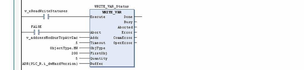
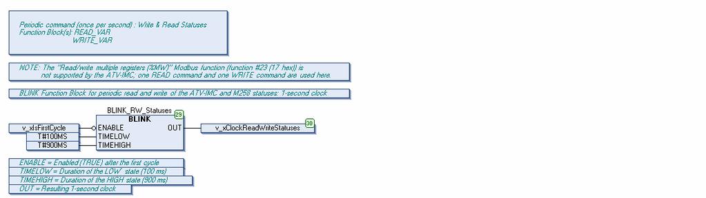
37 6. ST, LD, or CFC Program Step Action (***************************************************************************) (*** Modbus TCP Communications: ATV counter written back after each read ***) (*** Function Block(s): SINGLE_WRITE ***) (***************************************************************************) (* Update of the value of the copy of the counter produced by the ATV-IMC controller: Remote value of the Source *) v_wcounter_atv_copy_local := v_wcounter_atv_srce_remote; (* F_TRIG Function Block for detecting the end of the ATV counter read operation and trigerring the write operation *) F_TRIG_ReadAtvCounter_End.CLK := READ_VAR_Counter_ATV.Busy; F_TRIG_ReadAtvCounter_End(); (* Memorization of the end of the ATV counter read operation *) IF F_TRIG_ReadAtvCounter_End.Q THEN v_xmemreadatvcounter_end := TRUE; END_IF (* Command to write back the counter of the ATV-IMC: IF Address is OK *) (* AND at the (memorized) end of each read operation *) (* AND Previous write is finished *) IF v_xaddressisok_modbustcpatvimc AND v_xmemreadatvcounter_end AND NOT SINGLE_WRITE_Counter_ATV.Busy THEN v_xwritecounter_atv := TRUE; (* Reset of the memorization: Each read value is only sent back once *) v_xmemreadatvcounter_end := FALSE; END_IF (* SINGLE_WRITE Function Block for writing back the counter to the ATV-IMC controller *) (* NOTE: In ST language, this call syntax is required for Function Blocks of the *) (* "PLCCommunication" library that use an "Addr" INPUT variable (data type = ADDRESS) *) SINGLE_WRITE_Counter_ATV( (* IN - Rising Edge signal that triggers this Function Block *) Execute := v_xwritecounter_atv, (* IN - Function Block not aborted (FALSE) *) Abort := FALSE, (* IN - Formatted Modbus TCP address of the ATV-IMC controller *) Addr := v_addressmodbustcpatvimc, (* IN - Timeout of 500 ms *) Timeout := 5, (* IN - Type of object to be written: MW --> The Modbus function #6 (write single register) is used *) ObjType := ObjectType.MW, (* IN - Object to be written: The copy of the applicative counter of the ATV-IMC (address = %MW101) *) FirstObj := 101, (* IN - Value to write in the copy of the counter produced by the ATV-IMC controller *) theword := v_wcounter_atv_copy_local, (* OUT - This output is not used in this program *) Done =>, (* OUT - "Busy" output of the ATV counter write operation (this output will directly be used in the program) *) Busy =>, (* OUT - These outputs are not used in this program *) Aborted =>, Error =>, CommError =>, OperError => ); (* At the end of the current Modbus TCP write operation for the copy of the applicative counter of the ATV-IMC controller *) IF NOT SINGLE_WRITE_Counter_ATV.Busy THEN (* Resets the command to write back the counter of the ATV-IMC *) v_xwritecounter_atv := FALSE; END_IF (******************************************************************) (*** Periodic command (once per second) : Write & Read Statuses ***) (*** Function Block(s): READ_VAR ***) (*** WRITE_VAR ***) (******************************************************************) (* NOTE: The "Read/write multiple registers (%MW)" Modbus function (function #23 (17 hex)) is *) (* not supported by the ATV-IMC; one READ command and one WRITE command are used EIO /
38 6. ST, LD, or CFC Program Step Action here. *) (* BLINK Function Block for periodic read and write of the ATV-IMC and M258 statuses: 1- second clock *) (* IN - Enabled (TRUE) after the first cycle *) BLINK_RW_Statuses.ENABLE := NOT v_xisfirstcycle; (* IN - Duration of the LOW state (100 ms) *) BLINK_RW_Statuses.TIMELOW := T#100MS; (* IN - Duration of the HIGH state (900 ms) *) BLINK_RW_Statuses.TIMEHIGH := T#900MS; (* Function Block call *) BLINK_RW_Statuses(); (* OUT - Resulting 1-second clock *) v_xclockreadwritestatuses := BLINK_RW_Statuses.OUT; (* Command to read and write the ATV-IMC and M258 statuses: IF Address is OK AND Once per second (duration = 900 ms) *) v_xreadwritestatuses := v_xaddressisok_modbustcpatvimc AND v_xclockreadwritestatuses; (* WRITE_VAR Function Block for writing (sending) the M258 status into the ATV-IMC *) (* NOTE: In ST language, this call syntax is required for Function Blocks of the *) (* "PLCCommunication" library that use an "Addr" INPUT variable (data type = ADDRESS) *) WRITE_VAR_Status( (* IN - Rising Edge signal that triggers this Function Block *) Execute := v_xreadwritestatuses, (* IN - Function Block not aborted (FALSE) *) Abort := FALSE, (* IN - Formatted Modbus TCP address of the ATV-IMC controller *) Addr := v_addressmodbustcpatvimc, (* IN - Timeout of 500 ms *) Timeout := 5, (* IN - Type of object to be written: MW --> The Modbus function #16 (write multiple registers) is used *) ObjType := ObjectType.MW, (* IN - Object to be written: All addresses given below are addresses on the ATV-IMC controller *) (* %MD100 (%MW200+%MW201) = Controller Hardware Version of the M258 controller *) (* %MD101 (%MW202+%MW203) = Controller Coprocessor Version of the M258 controller *) (* %MW204 = State of the controller of the M258 controller *) FirstObj := 200, (* IN - Number of objects to write: 5 registers (2 DWORDs + 1 WORD) *) Quantity := 5, (* IN - Address of the CONSECUTIVE variables which values will be SENT to the ATV- IMC controller *) (* %MW60008 (DWORD) = Controller Hardware Version *) (* %MW60010 (DWORD) = Controller Coprocessor Version *) (* %MW60012 (WORD ) = State of the controller *) Buffer := ADR(PLC_R.i_dwHardVersion), (* OUT - This output is not used in this program *) Done =>, (* OUT - "Busy" output of the M258 status write operation (this output will directly be used in the program) *) Busy =>, (* OUT - These outputs are not used in this program *) Aborted =>, Error =>, CommError =>, OperError => ); (* READ_VAR Function Block for reading the ATV-IMC status *) (* NOTE: In ST language, this call syntax is required for Function Blocks of the *) (* "PLCCommunication" library that use an "Addr" INPUT variable (data type = ADDRESS) *) READ_VAR_Status( (* IN - Rising Edge signal that triggers this Function Block *) Execute := v_xreadwritestatuses, (* IN - Function Block not aborted (FALSE) *) Abort := FALSE, (* IN - Formatted Modbus TCP address of the ATV-IMC controller *) Addr := v_addressmodbustcpatvimc, (* IN - Timeout of 500 ms *) Timeout := 5, 38 EIO /2011
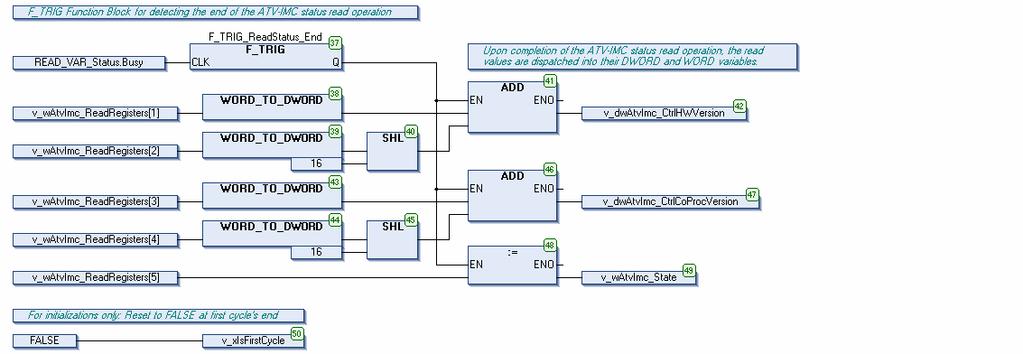
39 6. ST, LD, or CFC Program Step Action (* IN - Type of object to be read: MW --> The Modbus function #3 (read holding registers) is used *) ObjType := ObjectType.MW, (* IN - Object to be read: All addresses given below are addresses on the ATV-IMC controller *) (* %MD150 (%MW300+%MW301) = Copy of the Controller Hardware Version of the ATV- IMC controller *) (* %MD151 (%MW302+%MW303) = Copy of the Controller Coprocessor Version of the ATV-IMC controller *) (* %MW304 = Copy of the State of the controller of the ATV-IMC controller *) FirstObj := 300, (* IN - Number of objects to read: 5 registers (2 DWORDs + 1 WORD) *) Quantity := 5, (* IN - Address of the variables for RECEIVING the values of the status registers of the ATV-IMC controller *) Buffer := ADR(v_wAtvImc_ReadRegisters), (* OUT - This output is not used in this program *) Done =>, (* OUT - "Busy" output of the ATV-IMC status read operation (this output will directly be used in the program) *) Busy =>, (* OUT - These outputs are not used in this program *) Aborted =>, Error =>, CommError =>, OperError => ); (* F_TRIG Function Block for detecting the end of the ATV-IMC status read operation *) F_TRIG_ReadStatus_End.CLK := READ_VAR_Status.Busy; F_TRIG_ReadStatus_End(); (* Upon completion of the ATV-IMC status read operation, the read *) (* values are dispatched into their DWORD and WORD variables. *) IF F_TRIG_ReadStatus_End.Q THEN v_dwatvimc_ctrlhwversion := WORD_TO_DWORD(v_wAtvImc_ReadRegisters[1]) + SHL( WORD_TO_DWORD(v_wAtvImc_ReadRegisters[2]), 16 ); v_dwatvimc_ctrlcoprocversion := WORD_TO_DWORD(v_wAtvImc_ReadRegisters[3]) + SHL( WORD_TO_DWORD(v_wAtvImc_ReadRegisters[4]), 16 ); v_watvimc_state := v_watvimc_readregisters[5]; END_IF (* For initializations only: Reset to FALSE at first cycle's end *) v_xisfirstcycle := FALSE; EIO /

40 6. ST, LD, or CFC Program 6.2. LD Programs Before instructing you how to write down the LD program used in this example, the following table presents one optional step that gives you information on how to program in LD language. Step Action 1 Optional step How to display titles and comments in LD language Select the Options command of the Tools menu. Select, in the Options window, the FBD, LD and IL editor section. If you wish to add a title and/or a comment for each LD network, check the Show network title and/or the Show network comment options, as shown below: 40 EIO /2011
41 6. ST, LD, or CFC Program LD Program of the ATV-IMC Controller Step Action 1 Creation of the POU: Create a new POU in LD language, called PLC_PRG_ATVIMC_LD. Upon creation of this POU, it is automatically opened by SoMachine. 2 LD variables: In the upper part of the LD editor, declare the following variables: PROGRAM PLC_PRG_ATVIMC_LD VAR (*****************************) (*** Local/Remote Counters ***) (*****************************) (* Counter produced by the ATV-IMC controller: Local value of the Source (Read by the M258 controller) *) v_wcounter_atv_srce_local AT %MW100 : WORD := 0; (* Counter produced by the ATV-IMC controller: Remote value of the Copy (Written by the M258 controller) *) v_wcounter_atv_copy_remote AT %MW101 : WORD := 0; (* Counter produced by the ATV-IMC controller: Difference between the source and the copy *) v_icounter_atv_srce_delta : INT := 0; (* Flag reset to FALSE when the value of the local counter (only) has looped back from to 0 *) v_xnocounterloopback : BOOL := FALSE; (* Variable value = Remote value of the copy - Local value of the source *) v_dicounter_remoteminuslocal : DINT := 0; (***********************************************) (*** Variables for Receiving the M258 status ***) (***********************************************) EIO /
42 6. ST, LD, or CFC Program Step Action (* Controller Hardware Version of the M258 controller (DWORD at %MW60008), written (sent) by the M258 controller into %MD100 (%MW200 and %MW201) *) v_dwm258_ctrlhwversion AT %MD100 : DWORD := 0; (* Controller Coprocessor Version of the M258 controller (DWORD at %MW60010), written (sent) by the M258 controller into %MD101 (%MW202 and %MW203) *) v_dwm258_ctrlcoprocversion AT %MD101 : DWORD := 0; (* State of the M258 controller (WORD at %MW60012), written (sent) by the M258 controller into %MW204 *) v_wm258_state AT %MW204 : WORD := 0; (************************************************) (*** Variables for Sending the ATV-IMC status ***) (************************************************) (* %MD150 (%MW300 and %MW301) = Controller Hardware Version of the ATV-IMC controller (copy of the DWORD at %MW60008) *) v_dwatvimc_ctrlhwversion AT %MD150 : DWORD := 0; (* %MD151 (%MW302 and %MW303) = Controller Coprocessor Version of the ATV-IMC controller (copy of the DWORD at %MW60010) *) v_dwatvimc_ctrlcoprocversion AT %MD151 : DWORD := 0; (* %MW304 = State of the ATV-IMC controller (copy of the WORD at %MW60012) *) v_watvimc_state AT %MW304 : WORD := 0; END_VAR 3 LD program: In the lower part of the LD editor, implement the following program: 42 EIO /2011
43 6. ST, LD, or CFC Program Step Action EIO /
44 6. ST, LD, or CFC Program LD Program of the M258 Controller Step Action 1 Creation of the POU: Create a new POU in LD language, called PLC_PRG_M258_LD. Upon creation of this POU, it is automatically opened by SoMachine. 2 LD variables: Note: If you use another IP address than the IP address given below for the ATV-IMC controller, you must change the value of the c_saddressatvimc constant variable defined below (current value is ), as mentioned in IP Address Configuration (see page 25). In the upper part of the LD editor, declare the following variables: PROGRAM PLC_PRG_M258_LD VAR CONSTANT END_VAR VAR (* IP address of the ATV-IMC controller *) c_saddressatvimc : STRING := ' '; (* For initializations only: TRUE during first cycle only *) (* NOTE: Used so that the Function Blocks first see their "Execute" input *) (* as FALSE in order to detect a subsequent rising edge. *) v_xisfirstcycle : BOOL := TRUE; (**********************) (*** ADDM Variables ***) (**********************) 44 EIO /2011
45 6. ST, LD, or CFC Program Step Action (* Complete Modbus TCP address of the ATV-IMC (ATV-IMC card) *) v_saddressatvimc_card : STRING := ''; (* ADDM Function Block for formatting the Modbus TCP address of the ATV-IMC *) ADDM_ModbusTCP_ATVIMC : ADDM; (* ADDRESS structure for the Modbus TCP address of the ATV-IMC *) v_addressmodbustcpatvimc : ADDRESS; (* Result of the conversion of the Modbus TCP address of the ATV-IMC: OK if "Done" without any "Error" *) v_xaddressisok_modbustcpatvimc : BOOL := FALSE; (*************************************************************) (*** Variables for Reading the ATV-IMC applicative counter ***) (*************************************************************) (* Command to read the counter of the ATV-IMC: IF Address is OK AND Previous read is finished *) v_xreadcounter_atv : BOOL := FALSE; (* READ_VAR Function Block for reading the counter produced by the ATV-IMC controller *) READ_VAR_Counter_ATV : READ_VAR; (* Buffer for the value of the counter produced by the ATV-IMC controller: Remote value of the Source *) v_wcounter_atv_srce_remote : WORD := 0; (* Presence (TRUE) or absence (FALSE) of the ATV12 controller *) v_xpresenceatvimc : BOOL := FALSE; (* Communication error with the ATV-IMC controller (Timeout excluded) *) v_xcommerroratvimc : BOOL := FALSE; (* Flag set to TRUE if the current "CommError" result of the ATV counter read operation is a timeout error *) v_xreadcounter_timeouterror : BOOL := FALSE; (******************************************************************) (*** Variables for Writing back the ATV-IMC applicative counter ***) (******************************************************************) (* F_TRIG Function Block for detecting the end of the ATV counter read operation and trigerring the write operation *) F_TRIG_ReadAtvCounter_End : F_TRIG; (* Memorization of the end of the ATV counter read operation *) v_xmemreadatvcounter_end : BOOL := FALSE; (* Command to write back the counter of the ATV-IMC: IF Address is OK AND at the (memorized) end of each read operation *) v_xwritecounter_atv : BOOL := FALSE; (* Buffer for the value of the copy of the counter produced by the ATV-IMC controller: Local value of the Copy *) v_wcounter_atv_copy_local : WORD := 0; (* SINGLE_WRITE Function Block for writing back the counter to the ATV-IMC controller *) SINGLE_WRITE_Counter_ATV : SINGLE_WRITE; (****************************************************************************) (*** Variables for Writing the M258 status and Reading the ATV-IMC status ***) (****************************************************************************) (* BLINK Function Block for periodic write and read of the M258 and ATV-IMC statuses *) BLINK_RW_Statuses : BLINK; (* "OUT" output of the BLINK Function Block: Clock for writing and reading the M258 and ATV-IMC statuses *) v_xclockreadwritestatuses : BOOL := FALSE; (* Command to write and read the M258 and ATV-IMC statuses: IF Address is OK AND EIO /
) is not supported by the ATV-IMC; *) (* because of this, the standard \"Read Holding Registers\" and \"Write Multiple Registers\" Modbus functions (functions #03 and #16) are used.")
 v_watvimc_readregisters : ARRAY [1.")
46 6. ST, LD, or CFC Program Step Action Once per second (duration = 900 ms) *) v_xreadwritestatuses : BOOL := FALSE; (* NOTE: The "Read/write multiple registers (%MW)" Modbus function (function #23 (17 hex)) is not supported by the ATV-IMC; *) (* because of this, the standard "Read Holding Registers" and "Write Multiple Registers" Modbus functions (functions #03 and #16) are used. *) (* WRITE_VAR Function Block for writing the M258 status *) WRITE_VAR_Status : WRITE_VAR; (* READ_VAR Function Block for reading the ATV-IMC status *) READ_VAR_Status : READ_VAR; (* Registers read on the ATV-IMC by the M258 controller *) v_watvimc_readregisters : ARRAY [1..5] OF WORD := [5(0)]; *) (* F_TRIG Function Block for detecting the end of the ATV-IMC status read operation F_TRIG_ReadStatus_End : F_TRIG; (* Controller Hardware Version of the ATV-IMC controller (copy of the DWORD at %MW60008), read by the M258 controller *) v_dwatvimc_ctrlhwversion : DWORD := 0; (* Controller Coprocessor Version of the ATV-IMC controller (copy of the DWORD at %MW60010), read by the M258 controller *) v_dwatvimc_ctrlcoprocversion : DWORD := 0; (* State of the ATV-IMC controller (copy of the WORD at %MW60012), read by the M258 controller *) v_watvimc_state : WORD := 0; END_VAR 3 LD program: In the lower part of the LD editor, implement the following program: 46 EIO /2011
47 6. ST, LD, or CFC Program Step Action EIO /


48 6. ST, LD, or CFC Program Step Action 48 EIO /2011
49 6. ST, LD, or CFC Program Step Action EIO /
50 6. ST, LD, or CFC Program 6.3. CFC Programs CFC Program of the ATV-IMC Controller Step Action 1 Creation of the POU: Create a new POU in CFC language, called PLC_PRG_ATVINC_CFC. Upon creation of this POU, it is automatically opened by SoMachine. 50 EIO /2011
51 6. ST, LD, or CFC Program Step Action 2 CFC variables: In the upper part of the CFC editor, declare the following variables: PROGRAM PLC_PRG_ATVIMC_CFC VAR (*****************************) (*** Local/Remote Counters ***) (*****************************) (* Counter produced by the ATV-IMC controller: Local value of the Source (Read by the M258 controller) *) v_wcounter_atv_srce_local AT %MW100 : WORD := 0; (* Counter produced by the ATV-IMC controller: Remote value of the Copy (Written by the M258 controller) *) v_wcounter_atv_copy_remote AT %MW101 : WORD := 0; (* Counter produced by the ATV-IMC controller: Difference between the source and the copy *) v_icounter_atv_srce_delta : INT := 0; (***********************************************) (*** Variables for Receiving the M258 status ***) (***********************************************) (* Controller Hardware Version of the M258 controller (DWORD at %MW60008), written (sent) by the M258 controller into %MD100 (%MW200 and %MW201) *) v_dwm258_ctrlhwversion AT %MD100 : DWORD := 0; (* Controller Coprocessor Version of the M258 controller (DWORD at %MW60010), written (sent) by the M258 controller into %MD101 (%MW202 and %MW203) *) v_dwm258_ctrlcoprocversion AT %MD101 : DWORD := 0; (* State of the M258 controller (WORD at %MW60012), written (sent) by the M258 controller into %MW204 *) v_wm258_state AT %MW204 : WORD := 0; (************************************************) (*** Variables for Sending the ATV-IMC status ***) (************************************************) (* %MD150 (%MW300 and %MW301) = Controller Hardware Version of the ATV-IMC controller (copy of the DWORD at %MW60008) *) v_dwatvimc_ctrlhwversion AT %MD150 : DWORD := 0; (* %MD151 (%MW302 and %MW303) = Controller Coprocessor Version of the ATV-IMC controller (copy of the DWORD at %MW60010) *) v_dwatvimc_ctrlcoprocversion AT %MD151 : DWORD := 0; (* %MW304 = State of the ATV-IMC controller (copy of the WORD at %MW60012) *) v_watvimc_state AT %MW304 : WORD := 0; END_VAR EIO /


52 6. ST, LD, or CFC Program Step Action 3 CFC program: In the lower part of the CFC editor, implement the following program: 4 Order By Data Flow When you have finished implementing this CFC program, perform the following steps to correctly set the execution order of its blocks: Right-click on an empty spot of the central worksheet. In the Execution Order part of the contextual menu, execute the Order By Data Flow command. 52 EIO /2011
53 6. ST, LD, or CFC Program CFC Program of the M258 Controller Step Action 1 Creation of the POU: Create a new POU in CFC language, called PLC_PRG_M258_CFC. Upon creation of this POU, it is automatically opened by SoMachine. 2 CFC variables: Note: If you use another IP address than the IP address given below for the ATV-IMC controller, you must change the value of the c_saddressatvimc constant variable defined below (current value is ), as mentioned in IP Address Configuration (see page 25). In the upper part of the CFC editor, declare the following variables: PROGRAM PLC_PRG_M258_CFC VAR CONSTANT END_VAR VAR (* IP address of the ATV-IMC controller *) c_saddressatvimc : STRING := ' '; (* For initializations only: TRUE during first cycle only *) (* NOTE: Used so that the Function Blocks first see their "Execute" input *) (* as FALSE in order to detect a subsequent rising edge. *) v_xisfirstcycle : BOOL := TRUE; (**********************) (*** ADDM Variables ***) (**********************) EIO /
54 6. ST, LD, or CFC Program Step Action (* Complete Modbus TCP address of the ATV-IMC (ATV-IMC card) *) v_saddressatvimc_card : STRING := ''; (* ADDM Function Block for formatting the Modbus TCP address of the ATV-IMC *) ADDM_ModbusTCP_ATVIMC : ADDM; (* ADDRESS structure for the Modbus TCP address of the ATV-IMC *) v_addressmodbustcpatvimc : ADDRESS; (* Result of the conversion of the Modbus TCP address of the ATV-IMC: OK if "Done" without any "Error" *) v_xaddressisok_modbustcpatvimc : BOOL := FALSE; (*************************************************************) (*** Variables for Reading the ATV-IMC applicative counter ***) (*************************************************************) (* Command to read the counter of the ATV-IMC: IF Address is OK AND Previous read is finished *) v_xreadcounter_atv : BOOL := FALSE; (* READ_VAR Function Block for reading the counter produced by the ATV-IMC controller *) READ_VAR_Counter_ATV : READ_VAR; (* Buffer for the value of the counter produced by the ATV-IMC controller: Remote value of the Source *) v_wcounter_atv_srce_remote : WORD := 0; (* Presence (TRUE) or absence (FALSE) of the ATV12 controller *) v_xpresenceatvimc : BOOL := FALSE; (* Communication error with the ATV-IMC controller (Timeout excluded) *) v_xcommerroratvimc : BOOL := FALSE; (******************************************************************) (*** Variables for Writing back the ATV-IMC applicative counter ***) (******************************************************************) (* F_TRIG Function Block for detecting the end of the ATV counter read operation and trigerring the write operation *) F_TRIG_ReadAtvCounter_End : F_TRIG; (* Memorization of the end of the ATV counter read operation *) v_xmemreadatvcounter_end : BOOL := FALSE; (* Command to write back the counter of the ATV-IMC: IF Address is OK AND at the (memorized) end of each read operation *) v_xwritecounter_atv : BOOL := FALSE; (* Buffer for the value of the copy of the counter produced by the ATV-IMC controller: Local value of the Copy *) v_wcounter_atv_copy_local : WORD := 0; (* SINGLE_WRITE Function Block for writing back the counter to the ATV-IMC controller *) SINGLE_WRITE_Counter_ATV : SINGLE_WRITE; (****************************************************************************) (*** Variables for Writing the M258 status and Reading the ATV-IMC status ***) (****************************************************************************) *) (* BLINK Function Block for periodic write and read of the M258 and ATV-IMC statuses BLINK_RW_Statuses : BLINK; (* "OUT" output of the BLINK Function Block: Clock for writing and reading the M258 and ATV-IMC statuses *) v_xclockreadwritestatuses : BOOL := FALSE; (* Command to write and read the M258 and ATV-IMC statuses: IF Address is OK AND Once per second (duration = 900 ms) *) v_xreadwritestatuses : BOOL := FALSE; 54 EIO /2011
55 6. ST, LD, or CFC Program Step Action (* NOTE: The "Read/write multiple registers (%MW)" Modbus function (function #23 (17 hex)) is not supported by the ATV-IMC; *) (* because of this, the standard "Read Holding Registers" and "Write Multiple Registers" Modbus functions (functions #03 and #16) are used. *) (* WRITE_VAR Function Block for writing the M258 status *) WRITE_VAR_Status : WRITE_VAR; (* READ_VAR Function Block for reading the ATV-IMC status *) READ_VAR_Status : READ_VAR; (* Registers read on the ATV-IMC by the M258 controller *) v_watvimc_readregisters : ARRAY [1..5] OF WORD := [5(0)]; *) (* F_TRIG Function Block for detecting the end of the ATV-IMC status read operation F_TRIG_ReadStatus_End : F_TRIG; (* Controller Hardware Version of the ATV-IMC controller (copy of the DWORD at %MW60008), read by the M258 controller *) v_dwatvimc_ctrlhwversion : DWORD := 0; (* Controller Coprocessor Version of the ATV-IMC controller (copy of the DWORD at %MW60010), read by the M258 controller *) v_dwatvimc_ctrlcoprocversion : DWORD := 0; (* State of the ATV-IMC controller (copy of the WORD at %MW60012), read by the M258 controller *) v_watvimc_state : WORD := 0; END_VAR EIO /


56 6. ST, LD, or CFC Program Step Action 3 CFC program: In the lower part of the CFC editor, implement the following program: 56 EIO /2011


57 6. ST, LD, or CFC Program Step Action EIO /


58 6. ST, LD, or CFC Program Step Action 58 EIO /2011
59 6. ST, LD, or CFC Program Step Action 4 Order By Data Flow When you have finished implementing this CFC program, perform the following steps to correctly set the execution order of its blocks: Right-click on an empty spot of the central worksheet In the Execution Order part of the contextual menu, execute the Order By Data Flow command EIO /
 item. Double-click on the MAST task of the Task Configuration item. Click on the Add POU command.")
60 7. Running the Example 7. Running the Example 7.1. MAST Task Configuration MAST Task of the ATV-IMC Controller You must assign your PLC_PRG_ATVIMC program to the MAST task of the ATV- IMC controller. Step Action 1 In the Devices tree view: Expand the contents of the ATV_IMC_Controller (ATV-IMC S Type) item. Double-click on the MAST task of the Task Configuration item. Click on the Add POU command. 60 EIO /2011
, PLC_PRG_ATVIMC_ST, is selected: 3 Click on OK.")
61 7. Running the Example Step Action 2 In the Input Assistant window that appears: Select your program. In the following picture, the ST Program of the ATV-IMC Controller (see page 30), PLC_PRG_ATVIMC_ST, is selected: 3 Click on OK. This adds the selected POU to the list of programs run by the MAST task of the controller. EIO /
62 7. Running the Example Step Action 4 Optional step In the Configuration tab of the MAST task: Change the value of the Interval (e.g. t#200ms) parameter from 20 to 10. This change is optional. It is only designed to speed up the ATV-IMC s MAST task because it performs very few actions. 62 EIO /2011
63 7. Running the Example MAST Task of the M258 Controller You must assign your PLC_PRG_M258 program to the MAST task of the M258 controller. Step Action 1 In the Devices tree view: Expand the contents of the M258_Controller (TM258LF42DT4L) item. Double-click on the MAST task of the Task Configuration item. Click on the Add POU command. EIO /
64 7. Running the Example Step Action 2 In the Input Assistant window that appears: Select your program. In the following picture, the ST Program of the M258 Controller (see page 33), PLC_PRG_M258_ST, is selected: 3 Click on OK. This adds the selected POU to the list of programs run by the MAST task of the controller. 64 EIO /2011
65 7. Running the Example 7.2. Downloading the Example to the Controllers The steps listed in the following table describe how to download the two applications of this example to the ATV-IMC controller and to the M258 controller. Each of these applications must be downloaded into and run on its respective controller. If needed, please refer to the SoMachine online help for further information on these steps: search for Communication Settings. EIO /
66 7. Running the Example Downloading the Example to the ATV-IMC Controller Step Action 1 Connect the USB programming cable between your PC and the ATV-IMC controller. Please refer to Hardware Installation (see page 19) for the reference and usage of this cable. Note: You do not need to connect the ATV-IMC controller to the Ethernet network yet; this can be done later. 2 Check that the Application of the ATV_IMC_Controller (ATV-IMC S Type) is the active application of the project: in the Devices tree view, the Application item of this controller must appear in bold case. If this not the case, follow these steps: Right-click on this Application item. In the contextual menu that appears, select the Set Active Application command. 3 In the Devices tree view, double-click on the ATV_IMC_Controller (ATV-IMC S Type) item to open its configuration panel. 66 EIO /2011
67 7. Running the Example Step Action 4 In the Communication Settings tab of this panel. Click on the Gateway-1 node Click on the Scan network button If the controller is switched on and connected to your PC with the USB programming cable, it will be detected by SoMachine as shown below: In this example, the ATV-IMC controller has been detected. 5 Select this controller s node and click on the Set active path button. This will show SoMachine the way to reach your controller. Option: Uncheck the Secure online mode box to avoid validation messages during future online modifications. Note: The firmware version of your controller is displayed as the Target Version. EIO /
68 7. Running the Example Step Action 6 The following window will appear and ask you to confirm your choice: Read the hazard message; Press on both <Alt> and <F> keys to validate your choice and close this window; Or, click on the Cancel button if you can not comply with the statements in the hazard message. 7 Click on the Login button of the toolbar to establish a connection from SoMachine to the controller. 8a If you download the current project to the controller for the first time and if there is no project on the controller, the following window appears: 8b Click on Yes to download the Application software to the controller. If you download the current project to the controller for the first time and if there is another project on the controller, the following window appears: Click on Yes to download the Application software to the controller. 68 EIO /2011
69 7. Running the Example Step 8c Action If you already have downloaded the current project to the controller, the following window appears if you have brought new modifications to this project: 8d Select the Login with download choice. Click on OK to download the Application software to the controller. If you already have downloaded the current project to the controller, the connection is immediate if you brought no modification to this project. 9 Wait for the completion of the download operation. Once it is finished, the status bar of SoMachine displays the state of the controller: STOP 10 Click on the Start button of the toolbar to run the Application software on the controller. The state of the controller switches from STOP to RUN EIO /
70 7. Running the Example Connecting the ATV-IMC Controller to the Ethernet Network Step Action 1 Connect the ATV-IMC controller to the Ethernet network: Use a straight Ethernet cable between the ATV-IMC controller and an Ethernet hub (or switch), as mentioned in Hardware Installation (see page 19). Shortly after connecting the ATV-IMC controller to the Ethernet network, check that its G/Y ETH LED is either flashing green (activity at 100 Mbps) or flashing yellow (activity at 10 Mbps). Check that its G/R NS LED is either flashing green (IP address obtained) or solid green (at least one connection has been established). Note: If these two LEDs are not lit according to what is described here, you should refer to the Altivar ATV-IMC Drive Controller VW3A3521S0 Hardware Guide for the description of these LEDs. If these LEDs report an Ethernet configuration error, you shall go back to IP Address Configuration (see page 25) and review the Ethernet configuration of the ATV-IMC controller. Please contact your system administrator if you need assistance in configuring the network settings of your ATV-IMC controller. 2 In the Watch part of the View menu, execute the Watch 1 command. 3 In the table of the Watch 1 panel that appears: Click on an empty cell of the Expression column to select this cell. Click again on this cell to edit its contents. Write ETH_R, as shown below: Press the <ENTER> key to validate this watch expression; SoMachine automatically completes this expression to adapt it to the currently active application: 70 EIO /2011

71 7. Running the Example Step Action Expand the contents of the ATV_IMC_Controller.Application.ETH_R structure, including its i_byipaddress, i_bysubnetmask, and i_bygateway arrays: Check that the contents of these three arrays match the Ethernet configuration you set for the ATV-IMC controller during IP Address Configuration (see page 25). Note: If there is a mismatch between these values, you shall go back to IP Address Configuration (see page 25) and review the Ethernet configuration of the ATV-IMC controller. Please contact your system administrator if you need assistance in configuring the network settings of your ATV-IMC controller. EIO /

72 7. Running the Example Step Action 4 Check that the ATV-IMC controller really uses the IP address it was assigned: Execute the Run command of the Windows Start menu. In the Run window that appears, write cmd. Click on OK. In the window that appear, execute the following command: ping -t Note: Replace the address by the IP address you gave to your ATV-IMC controller during IP Address Configuration (see page 25). The ATV-IMC controller shall reply to this command, as shown below: Stop this PING command by pressing the <Ctrl> and <C> keys. Note: If the result of the PING command is Request timed out., then you shall go back to IP Address Configuration (see page 25) and review the Ethernet configuration of the ATV-IMC controller. Please contact your system administrator if you need assistance in configuring the network settings of your ATV-IMC controller. 5 Click on the Logout button of the toolbar to disconnect SoMachine from the controller. 72 EIO /2011
73 7. Running the Example Step Action 6 Disconnect the USB programming cable from the ATV-IMC controller. As long as this cable is disconnected, SoMachine can only reach the ATV-IMC controller through the Ethernet network. 7 In the Communication Settings tab of the ATV_IMC_Controller configuration panel. Click on the Gateway-1 node Click on the Scan network button If the controller is switched on and connected to the same Ethernet network than your PC, it will be detected by SoMachine as shown below: In this example, the ATV-IMC controller has been detected with a new access path (e.g. [ DE] for the Ethernet connection). The previously used access path (e.g. [ ] for the USB connection) is set in italics to mark it as being invalid. 8 Select this controller s node and click on the Set active path button. This will show SoMachine the way to reach your controller. EIO /
74 7. Running the Example Step Action 9 The following window will appear and ask you to confirm your choice: Read the hazard message; Press on both <Alt> and <F> keys to validate your choice and close this window; Or, click on the Cancel button if you can not comply with the statements in the hazard message. 10 Click on the Login button of the toolbar to establish a connection from SoMachine to the controller. Note: Since you already downloaded the Application software to the controller and switched the controller from STOP to RUN, the connection is nearly instantaneous and the controller is already in RUN state. 74 EIO /2011
75 7. Running the Example Downloading the Example to the M258 Controller Step Action 1 Connect the USB programming cable between your PC and the M258 Controller. Please refer to Hardware Installation (see page 19) for the reference and usage of this cable. Note: You do not need to connect the M258 controller to the Ethernet network yet; this can be done later. 2 Set the Application of the M258_Controller (TM258LF42DT4L) as the active application of the project: Right-click on this Application item. In the contextual menu that appears, select the Set Active Application command. 3 In the Devices tree view, double-click on the M258_Controller (TM258LF42DT4L) item to open its configuration panel. EIO /

76 7. Running the Example Step Action 4 In the Communication Settings tab of this panel. Click on the Gateway-1 node Click on the Scan network button If the controller is switched on and connected to your PC with the USB programming cable, it will be detected by SoMachine as shown below: In this example, the controller has been detected. 5 Select this controller s node and click on the Set active path button. This will show SoMachine the way to reach your controller. Option: Uncheck the Secure online mode box to avoid validation messages during future online modifications. Note: The firmware version of your controller is displayed as the Target Version. 76 EIO /2011

77 7. Running the Example Step Action 6 The following window will appear and ask you to confirm your choice: Read the hazard message; Press on both <Alt> and <F> keys to validate your choice and close this window; Or, click on the Cancel button if you can not comply with the statements in the hazard message. 7 Click on the Login button of the toolbar to establish a connection from SoMachine to the controller. 8a If you download the current project to the controller for the first time and if there is no project on the controller, the following window appears: 8b Click on Yes to download the Application software to the controller. If you download the current project to the controller for the first time and if there is another project on the controller, the following window appears: Click on Yes to download the Application software to the controller. EIO /

78 7. Running the Example Step 8c Action If you already have downloaded the current project to the controller, the following window appears if you have brought new modifications to this project: 8d Select the Login with download choice. Click on OK to download the Application software to the controller. If you already have downloaded the current project to the controller, the connection is immediate if you brought no modification to this project. 9 Wait for the completion of the download operation. Once it is finished, the status bar of SoMachine displays the state of the controller: STOP 10 Click on the Start button of the toolbar to run the Application software on the controller. The state of the controller switches from STOP to RUN 78 EIO /2011
79 7. Running the Example Connecting the M258 Controller to the Ethernet Network Step Action 1 Connect the M258 controller to the Ethernet network: Use a straight Ethernet cable between the M258 controller and an Ethernet hub (or switch), as mentioned in Hardware Installation (see page 19). Shortly after connecting the M258 controller to the Ethernet network, check that its Eth LA LED is either flashing green (activity at 100 Mbit/s) or flashing yellow (activity at 10 Mbit/s). Check that its Eth ST LED is solid green (port connected and IP address obtained). Note: If these two LEDs are not lit according to what is described here, you should refer to the Modicon M258 Logic Controller Hardware Guide for the description of these LEDs. If these LEDs report an Ethernet configuration error, you shall go back to IP Address Configuration (page 26) and review the Ethernet configuration of the M258 controller. Please contact your system administrator if you need assistance in configuring the network settings of your M258 controller. 2 If you have closed the Watch 1 panel, open it again: In the Watch part of the View menu, execute the Watch 1 command. 3 In the table of the Watch 1 panel that appears: Click on an empty cell of the Expression column to select this cell. Note: The table of the Watch 1 panel is not empty since you already have written the ATV_IMC_Controller.Application.ETH_R watch expression. Click again on this cell to edit its contents. Write ETH_R, as shown below: Press the <ENTER> key to validate this watch expression; SoMachine automatically completes this expression to adapt it to the currently active application: EIO /

80 7. Running the Example Step Action Expand the contents of the M258_Controller.Application.ETH_R structure, including its i_byipaddress, i_bysubnetmask, and i_bygateway arrays: Check that the contents of these three arrays match the Ethernet configuration you set for the M258 controller during the IP Address Configuration (see page 26). Note: If there is a mismatch between these values, you shall go back to IP Address Configuration (see page 26) and review the Ethernet configuration of the M258 controller. Please contact your system administrator if you need assistance in configuring the network settings of your M258 controller. 80 EIO /2011

81 7. Running the Example Step Action 4 Check that the M258 controller really uses the IP address it was assigned: Execute the Run command of the Windows Start menu. In the Run window that appears, write cmd. Click on OK. In the window that appear, execute the following command: ping -t Note: Replace the address by the IP address you gave to your M258 controller during the IP Address Configuration (see page 26). The M258 controller shall reply to this command, as shown below: Stop this PING command by pressing the <Ctrl> and <C> keys. Note: If the result of the PING command is Request timed out., then you shall go back to IP Address Configuration (see page 26) and review the Ethernet configuration of the M258 controller. Please contact your system administrator if you need assistance in configuring the network settings of your M258 controller. 5 Click on the Logout button of the toolbar to disconnect SoMachine from the controller. EIO /

82 7. Running the Example Step Action 6 Disconnect the USB programming cable from the M258 controller. As long as this cable is disconnected, SoMachine can only reach the M258 controller through the Ethernet network. 7 In the Communication Settings tab of the M258_Controller configuration panel. Click on the Gateway-1 node Click on the Scan network button If the controller is switched on and connected to the same Ethernet network than your PC, it will be detected by SoMachine as shown below: In this example, the controller has been detected with a new access path (e.g. [0000.B0DF] for the Ethernet connection). The previously used access path (e.g. [ ] for the USB connection) is set in italics to mark it as being invalid. 8 Select this controller s node and click on the Set active path button. This will show SoMachine the way to reach your controller. 82 EIO /2011
83 7. Running the Example Step Action 9 The following window will appear and ask you to confirm your choice: Read the hazard message; Press on both <Alt> and <F> keys to validate your choice and close this window; Or, click on the Cancel button if you can not comply with the statements in the hazard message. 10 Click on the Login button of the toolbar to establish a connection from SoMachine to the controller. Note: Since you already downloaded the Application software to the controller and switched the controller from STOP to RUN, the connection is nearly instantaneous and the controller is already in RUN state. EIO /

84 7. Running the Example 7.3. Running the Example on the ATV-IMC and M258 Controllers The steps listed in the following table describe how to use the two applications of this example, once they have been downloaded to the ATV-IMC and M258 controllers. It is assumed here that each of these applications has been downloaded into and run on its respective controller. Step Action 1 Requirements First, you must be connected to the ATV-IMC controller and to the M258 controller through the Ethernet network. Please refer to Downloading the Example to the Controllers (see page 65). Notes: Being connected to both of these controllers makes it easier for you to monitor the variables and the behavior of the programs running on both controllers. Any command such as Start, Stop, Logout, and so on, affects the currently active application, that is, the Application item which name is in bold case. In the screenshot presented above, for instance, the currently active application is the Application of the M258 controller. With a SoMachine project, you can activate any of its applications by performing the Set Active Application command described in this very same chapter (see page 66). SoMachine also features such commands as Multiple Download (available in the Online menu) for performing specific commands on multiple target devices. Please refer to the SoMachine online help for further information on such commands: search for Multiple Download. 84 EIO /2011

85 7. Running the Example Step Action 2 In the Devices tree view: Expand the contents of the ATV_IMC_Controller (ATV-IMC S Type) item. Double-click on your PLC_PRG_ATVIMC program to open it (e.g. PLC_PRG_ATVIMC_ST if you previously selected this program as the program run by the MAST task of your ATV-IMC controller). This command opens your program in the central panel of SoMachine; the online values of the variables used by this program are also displayed, as shown below: EIO /

86 7. Running the Example Step Action 3 Likewise, in the Devices tree view: Expand the contents of the M258_Controller (TM258LF42DT4L) item. Double-click on your PLC_PRG_M258 program to open it (e.g. PLC_PRG_M258_ST if you previously selected this program as the program run by the MAST task of your M258 controller). This command opens your program in the central panel of SoMachine; the online values of the variables used by this program are also displayed, as shown below: Note: Being connected to both controllers allows you to monitor the variables and the behavior of both of them. Thus, you can easily and quickly go from one application to the other. 4 Addressing the ATV-IMC controller s card using the ADDM Function Block: Name of the ADDM Function Block instance: ADDM_ModbusTCP_ATVIMC To format the Modbus TCP address of the ATV-IMC controller s card, the ADDM_ModbusTCP_ATVIMC instance is used. The addr input of this instance is given a STRING whose format is <communication port number> {<IP address A.B.C.D>}<slave address>, as mentioned in the SoMachine Modbus and ASCII Read/Write Functions PLCCommunication Library Guide. In the case of this example, this STRING is equal to 3{ }252 because: <communication port number> = 3: Number of the embedded Ethernet port (on the M258 controller). <IP address A.B.C.D> = : IP address configured for the ATV-IMC controller in IP Address Configuration (see page 25). <slave address> = 252: The UnitId that corresponds to the ATV-IMC card. This value is described in the ATV IMC Drive Controller Programming Guide. If this UnitId is omitted, then a default value (255) is used by the ADDM_ModbusTCP_ATVIMC instance; in the case of the ATV-IMC controller, this default address corresponds to its IO Scanner. 86 EIO /2011
SoMachine. M238 High Speed Counting Functions High_Speed_Counter_M238.project Example Guide. 04/2012 Basic. Intermediate Expert
 SoMachine M238 High Speed Counting Functions High_Speed_Counter_M238.project Example Guide 04/2012 Basic Intermediate Expert EIO0000000905.00 www.schneider-electric.com The information provided in this
SoMachine Scan for Buttons Linked to ZBRN Modules Harmony ZBRN Library Guide
 SoMachine EIO0000001868 11/2016 SoMachine Scan for Buttons Linked to ZBRN Modules Harmony ZBRN Library Guide 11/2016 EIO0000001868.04 www.schneider-electric.com The information provided in this documentation
Packaging User Guide for Temperature Control M221 Project Template
 Packaging EIO0000001762 04/2014 Packaging User Guide for Temperature Control M221 Project Template 04/2014 EIO0000001762.00 www.schneider-electric.com The information provided in this documentation contains
LXM32. Explanation for detected error E 733F. Expert Support Machine Solution
 LXM32 Explanation for detected error E 733F Expert Support Machine Solution The information provided in this documentation contains general descriptions and/or technical characteristics of the performance
Ethernet Modbus X80 Gateway Device Type Manager
 Ethernet Modbus X80 Gateway Device Type Manager EIO0000001315 10/2012 Ethernet Modbus X80 Gateway Device Type Manager User Manual 10/2012 EIO0000001315.00 www.schneider-electric.com The information provided
SoMachine. M258 PLC Diagnostic PLC_Diagnostic_M258.project Example Guide. 04/2012 Basic. Intermediate Expert.
 SoMachine M258 PLC Diagnostic PLC_Diagnostic_M258.project Example Guide 04/2012 Basic Intermediate Expert EIO0000000915.00 www.schneider-electric.com The information provided in this documentation contains
5521 Potentiometer Analog Input Module
 55 Potentiometer Analog Input Installation, Operation and Maintenance Setup Manual 5/9/0 Safety Information The information provided in this documentation contains general descriptions and/or technical
5504 Thermocouple Analog Input Module
 550 Thermocouple Analog Input Installation, Operation and Maintenance Setup Manual 5/9/0 Safety Information The information provided in this documentation contains general descriptions and/or technical
SCADAPack E Target 5 DF1 PLC Interface
 SCADAPack E Target 5 DF1 PLC Interface 2 Table of Contents Part I 3 1 Technical... Support 3 2 Safety... Information 4 3 Overview... 7 4 I/O Device... Interface 7 4.1 Input Devices... 9 4.2 Output Devices...
SCADAPack E Idec PLC Interface Manual
 SCADAPack E Idec PLC Interface Manual 2 SCADAPack E Idec PLC Interface Manual Table of Contents Part I Idec PLC Interface 3 1 Technical... Support 3 2 Safety... Information 4 3 Preface... 6 4 Overview...
Schneider Electric Floating License Manager
 Schneider Electric Floating License Manager EIO0000001078 11/2012 Schneider Electric Floating License Manager User Manual 12/2012 EIO0000001078.01 www.schneider-electric.com The information provided in
SCADAPack E ISaGRAF Quick Start Guide
 SCADAPack E ISaGRAF Quick Start Guide 2 SCADAPack E ISaGRAF Quick Start Guide Table of Contents Part I ISaGRAF 3 Quick Start Guide 3 1 Technical... Support 3 2 Safety... Information 4 3 Preface... 6 4
Modicon M241 Logic Controller High Speed Counting HSC Library Guide
 Modicon M241 Logic Controller EIO0000001444 04/2014 Modicon M241 Logic Controller High Speed Counting HSC Library Guide 04/2014 EIO0000001444.02 www.schneider-electric.com The information provided in this
5401 and 5402 Digital I/O Modules
 50 and 50 Digital I/O Modules Installation, Operation and Maintenance Setup Manual 5/9/0 Safety Information The information provided in this documentation contains general descriptions and/or technical
Schneider Electric License Manager
 Schneider Electric License Manager EIO0000001070 11/2012 Schneider Electric License Manager User Manual 12/2012 EIO0000001070.01 www.schneider-electric.com The information provided in this documentation
SoMachine Modbus TCP IOScanner
 SoMachine Modbus TCP IOScanner EIO0000001456 09/2014 SoMachine Modbus TCP IOScanner User Guide 09/2014 EIO0000001949.00 www.schneider-electric.com The information provided in this documentation contains
Modicon M258 Logic Controller
 Modicon M258 Logic Controller EIO0000000572 04/2012 Modicon M258 Logic Controller High Speed Counting M258 Expert I/O Library Guide 04/2012 EIO0000000572.04 www.schneider-electric.com The information provided
Acti 9 Communication System
 Acti 9 Communication System Diagnostics User Manual 05/2012 DOCA0042EN-00 www.schneider-electric.com This document contains general descriptions and/or general technical specifications of the products
EcoStruxure Power Commission Installation Guide
 EcoStruxure Power Commission DOCA0134EN 03/2019 EcoStruxure Power Commission Installation Guide 03/2019 DOCA0134EN-04 www.schneider-electric.com The information provided in this documentation contains
Modicon M241 Logic Controller High Speed Counting HSC Library Guide
 Modicon M241 Logic Controller EIO0000001444 03/2018 Modicon M241 Logic Controller High Speed Counting HSC Library Guide 03/2018 EIO0000001444.04 www.schneider-electric.com The information provided in this
Modicon TM3 (SoMachine Basic) Expansion Modules Configuration Programming Guide
 Expansion Modules Configuration Programming Guide") Modicon TM3 (SoMachine Basic) EIO0000001396 12/2015 Modicon TM3 (SoMachine Basic) Expansion Modules Configuration Programming Guide 12/2015 EIO0000001396.05 www.schneider-electric.com The information provided
Modicon TM3 (SoMachine Basic) EIO0000001396 12/2015 Modicon TM3 (SoMachine Basic) Expansion Modules Configuration Programming Guide 12/2015 EIO0000001396.05 www.schneider-electric.com The information provided
Momentum 170ENT11001/170ENT11002 Ethernet Communications Adapter User Guide
 Momentum 31004109 09/2017 Momentum 170ENT11001/170ENT11002 Ethernet Communications Adapter User Guide 09/2017 31004109.07 www.schneider-electric.com The information provided in this documentation contains
5403 and 5404 Digital Input Modules
 503 and 50 Digital Input Modules Installation, Operation and Maintenance Setup Manual //07 Copyright 0-07 Schneider Electric Canada Inc. All rights reserved. 503 and 50 Digital Input Modules The information
EIO /2011. Magelis HMISTO501. Zelio/Millenium Driver 07/2011 EIO
 EIO0000001026 07/2011 Magelis HMISTO501 Zelio/Millenium Driver 07/2011 EIO0000001026.00 www.schneider-electric.com 2 EIO0000001026 07/2011 Table of Contents Safety Information.............................
Modicon M238 Logic Controller
 EIO0000000384 10/2010 Modicon M238 Logic Controller Programming Guide 10/2010 EIO0000000384.02 www.schneider-electric.com The information provided in this documentation contains general descriptions and/or
How Can I. Integrate a Third-Party Modbus Device with PowerSCADA Expert? System Technical Note PowerSCADA Expert V1.0
 How Can I Integrate a Third-Party Modbus Device with PowerSCADA Expert? System Technical Note PowerSCADA Expert V1.0 Safety Information Important Information Read these instructions carefully before trying
Magelis XBTGC HMI Controller Programming Guide
 Magelis XBTGC HMI Controller EIO0000000632 04/2014 Magelis XBTGC HMI Controller Programming Guide 04/2014 EIO0000000632.07 www.schneider-electric.com The information provided in this documentation contains
Unity Pro OSLoader User Manual
 Unity Pro 35006156 12/2015 Unity Pro OSLoader User Manual 12/2015 35006156.14 www.schneider-electric.com The information provided in this documentation contains general descriptions and/or technical characteristics
Altivar ATV IMC Drive Controller Programming Guide
 Altivar ATV IMC Drive Controller EIO0000000390 12/2015 Altivar ATV IMC Drive Controller Programming Guide 12/2015 EIO0000000390.09 www.schneider-electric.com The information provided in this documentation
Altivar ATV IMC Drive Controller Programming Guide
 Altivar ATV IMC Drive Controller EIO0000000390 04/2014 Altivar ATV IMC Drive Controller Programming Guide 04/2014 EIO0000000390.08 www.schneider-electric.com The information provided in this documentation
XPSMCMx Fieldbus Expansion Modules Instruction Sheet (Original Language)
") XPSMCMx Fieldbus Expansion Modules EAV8283001 12/2014 XPSMCMx Fieldbus Expansion Modules Instruction Sheet (Original Language) 12/2014 EAV8283001.00 www.schneider-electric.com The information provided
XPSMCMx Fieldbus Expansion Modules EAV8283001 12/2014 XPSMCMx Fieldbus Expansion Modules Instruction Sheet (Original Language) 12/2014 EAV8283001.00 www.schneider-electric.com The information provided
Schneider Electric AB DH485 Protocol XBT N/R/RT
 Schneider Electric AB DH485 Protocol XBT N/R/RT 33004016 06/2008 33004016.01 2 33004016 06/2008 Table of Contents Safety Information....................................5 About the Book.......................................7
Magelis SCU HMI Controller PLCSystem Library Guide
 Magelis SCU EIO0000001246 02/2014 Magelis SCU HMI Controller PLCSystem Library Guide 02/2014 EIO0000001246.02 www.schneider-electric.com The information provided in this documentation contains general
Modicon TM2 (SoMachine Basic) Expansion Modules Configuration Programming Guide
 Expansion Modules Configuration Programming Guide") Modicon TM2 (SoMachine Basic) EIO0000001390 12/2015 Modicon TM2 (SoMachine Basic) Expansion Modules Configuration Programming Guide 12/2015 EIO0000001390.03 www.schneider-electric.com The information provided
Modicon TM2 (SoMachine Basic) EIO0000001390 12/2015 Modicon TM2 (SoMachine Basic) Expansion Modules Configuration Programming Guide 12/2015 EIO0000001390.03 www.schneider-electric.com The information provided
Altivar ATV IMC Drive Controller Hardware Guide
 Altivar ATV IMC Drive Controller S1A10252 04/2014 Altivar ATV IMC Drive Controller Hardware Guide 04/2014 S1A10252.08 www.schneider-electric.com The information provided in this documentation contains
SCADAPack E ISaGRAF 3 I/O Connection Reference
 SCADAPack E ISaGRAF 3 I/O Connection Reference 2 SCADAPack E ISaGRAF 3 I/O Connection Reference Table of Contents Part I ISaGRAF 3 I/O Connection 4 1 Technical... Support 4 2 Safety... Information 5 3
Modicon TM4 Expansion Modules Programming Guide
 Modicon TM4 EIO0000001802 11/2015 Modicon TM4 Expansion Modules Programming Guide 11/2015 EIO0000001802.02 www.schneider-electric.com The information provided in this documentation contains general descriptions
StruxureWare Power Monitoring 7.0
 StruxureWare Power Monitoring 7.0 OPC Server Assistant 7EN02-0309-00 02/2012 Contents Safety information 5 Introduction 7 Scope 7 Optional OPC Server License 8 OPC Server Type 8 OPC Server Support 9 Creating/Updating
Magelis SCU HMI Controller Programming Guide
 Magelis SCU EIO0000001240 02/2014 Magelis SCU HMI Controller Programming Guide 02/2014 EIO0000001240.04 www.schneider-electric.com The information provided in this documentation contains general descriptions
PowerLogic ION7550 RTU option
 70052-0213-02 PRODUCT OPTION 01/2011 PowerLogic ION7550 RTU option The PowerLogic ION7550 Remote Terminal Unit (RTU) option is designed for data acquisition from WAGES (water, air, gas, electricity, steam)
Web Designer for Modicon M340, Premium and Quantum
 Web Designer for Modicon M340, Premium and Quantum 35016149 08/2012 Web Designer for Modicon M340, Premium and Quantum User Manual 08/2012 35016149.05 www.schneider-electric.com The information provided
Smart Mode Measurements
 Smart Mode Measurements Technical Reference for Maintenance PME 7.2.3 V1.0 Safety Information Important Information Read these instructions carefully before trying to install, configure, or operate this
Logipam. SFT2885 Programming Software for Sepam Series 80 User s Manual 01/ SEPED303004EN. Logipam
 Logipam SEPED303004EN 01/2013 Logipam SFT2885 Programming Software for Sepam Series 80 User s Manual 01/2013 SEPED303004EN www.schneider-electric.com The information provided in this documentation contains
Security Quick Start Guide
 2 Table of Contents Part I 4 1 Technical... Support 4 2 Safety... Information 5 3 Introduction... 7 4 Security... Overview 8 5 How to... Configure DNP3 Secure Authentication 11 5.1 Check RTU Firm... w
5502 Differential Analog Input Module
 550 Differential Analog Input Installation, Operation and Maintenance Setup Manual //07 Copyright 0-07 Schneider Electric Canada Inc. All rights reserved. 550 Differential Analog Input The information
Unity Loader A SoCollaborative Software User Manual
 Unity Loader 33003805 02/2017 Unity Loader A SoCollaborative Software User Manual 02/2017 33003805.11 www.schneider-electric.com The information provided in this documentation contains general descriptions
Modicon M340 for Ethernet Communications Modules and Processors User Manual
 Modicon M340 for Ethernet 31007131 12/2018 Modicon M340 for Ethernet Communications Modules and Processors User Manual (Original Document) 12/2018 31007131.16 www.schneider-electric.com The information
SCADAPack E 5405 Digital Input Hardware Manual
 SCADAPack E 5405 Digital Input Hardware Manual 2 SCADAPack E 5405 Digital Input Hardware Manual Table of Contents Part I 5405 Digital Input Module 3 1 Technical... Support 3 2 Safety... Information 4 3
SoMachine HVAC v2.2. Release Notes
 Software / Firmware Version: SoMachine HVAC v2.2 Release Notes TM171PDM27 PV: 01, RL: 04 SV: 423.24 TM171PBM27R PV: 01, RL: 04 SV: 477.24 TM171PFE03 PV: 01, RL: 04 SV: 489.17 TM171DGRP PV: 01, RL: 04 SV:
Change Report Colors and Logo
 How to Change Report Colors and Logo Report Developer Kit V1.0 Safety Information Important Information Read these instructions carefully before trying to install, configure, or operate this software.
SCADAPack E Koyo DirectNET PLC Interface Manual
 SCADAPack E Koyo DirectNET PLC Interface Manual 2 SCADAPack E Koyo DirectNET PLC Interface Manual Table of Contents Part I Koyo DirectNET PLC Interface 3 1 Technical... Support 3 2 Safety... Information
SoMachine Motion Control Library Guide
 SoMachine EIO0000002221 05/2017 SoMachine Motion Control Library Guide 05/2017 EIO0000002221.02 www.schneider-electric.com The information provided in this documentation contains general descriptions and/or
Magelis SCU HMI Controller Programming Guide
 Magelis SCU EIO0000001240 12/2016 Magelis SCU HMI Controller Programming Guide 12/2016 EIO0000001240.06 www.schneider-electric.com The information provided in this documentation contains general descriptions
Altivar 61/71. Variable speed drives for synchronous and asynchronous motors. POWERLINK Communication Manual VW3A /2013
 Altivar 61/71 S1B56379 07/2013 Altivar 61/71 Variable speed drives for synchronous and asynchronous motors POWERLINK Communication Manual VW3A3321 07/2013 S1B56379.01 www.schneider-electric.com The information
Modicon M580 Standalone System Planning Guide for Frequently Used Architectures
 Modicon M580 Standalone HRB62666 06/2016 Modicon M580 Standalone System Planning Guide for Frequently Used Architectures 06/2016 HRB62666.05 www.schneider-electric.com The information provided in this
Modbus Plus to Ethernet Bridge 174 CEV User Guide
 31005104 2/2010 Modbus Plus to Ethernet Bridge 174 CEV 200 40 User Guide 2/2010 31005104.03 www.schneider-electric.com The information provided in this documentation contains general descriptions and/or
StruxureWare Power Monitoring Expert 8.0 Data Center Edition
 StruxureWare Power Monitoring Expert 8.0 Data Center Edition Breaker Performance Guide 7EN02-0367-01 06/2015 Safety information Important information Read these instructions carefully and look at the
StruxureWare. Power Monitoring Expert 8.2 Hierarchy Manager Help Topics 7EN /2017
 StruxureWare Power Monitoring Expert 8.2 Hierarchy Manager Help Topics 7EN52-0413-00 03/2017 Legal Information The Schneider Electric brand and any registered trademarks of Schneider Electric Industries
TeSys U LULC07 Profibus DP Communication Module
 1672612 03/2009 TeSys U LULC07 Profibus DP Communication Module Acyclic Data Read/Write with Siemens Application Note 03/2009 1672612 www.schneider-electric.com Schneider Electric assumes no responsibility
VW3A3521S0 ATV IMC drive controller card type S solutions
 Product data sheet Characteristics ATV IMC drive controller card type S solutions Main Range of product Product or component type Module configuration Product specific application Discrete I/O number 16
Premium Hot Standby with Unity User Manual
 Premium 35012068 04/2015 Premium Hot Standby with Unity User Manual 04/2015 35012068.12 www.schneider-electric.com The information provided in this documentation contains general descriptions and/or technical
PowerLogic TM Series E4800 Multi-Circuit Meters. Configuration Guide
 PowerLogic TM Series E4800 Multi-Circuit Meters Configuration Guide PowerLogic TM E4800 Series 930-112-01 02/2009 Hazard Categories and Special Symbols Read these instructions carefully and look at the
5910 Ethernet Gateway Module
 Hardware Manual 2/24/2017 Copyright 2014-2017 Schneider Electric Canada Inc. All rights reserved. 5910 Ethernet Gateway Module The information provided in this documentation contains general descriptions
TeSys UASILUFC5 - ASILUFC51 AS-i Communication Module
 1639093 03/2009 TeSys UASILUFC5 - ASILUFC51 AS-i Communication Module User Manual 03/2009 1639093 www.schneider-electric.com Schneider Electric assumes no responsibility for any errors that may appear
Compact CANopen Logic Controller M241 System User Guide
 Compact CANopen Logic Controller M241 EIO0000001677 06/2014 Compact CANopen Logic Controller M241 System User Guide 06/2014 EIO0000001677.01 www.schneider-electric.com The information provided in this
Modicon LMC078 Motion Controller Programming Guide
 Modicon LMC078 EIO0000001909 11/2015 Modicon LMC078 Motion Controller Programming Guide 11/2015 EIO0000001909.01 www.schneider-electric.com The information provided in this documentation contains general
File Synchronization User Guide
 Eurotherm PAC User Guide Issue 2 April 2018 HA033151/2 Legal Information The information provided in this documentation contains general descriptions and/or technical characteristics of the performance
TeSys T LTM R EtherNet/IP with a Third-Party PLC Quick Start Guide
 TeSys TLTMR EtherNet/IP with a Third-Party PLC DOCA0119EN-00 06/2015 TeSys T LTM R EtherNet/IP with a Third-Party PLC Quick Start Guide 06/2015 DOCA0119EN-00 www.schneider-electric.com The information
Unity Loader A SoCollaborative Software User Manual
 Unity Loader 33003805 06/2015 Unity Loader A SoCollaborative Software User Manual 06/2015 33003805.10 www.schneider-electric.com The information provided in this documentation contains general descriptions
Galaxy Shore Connection 500 kva. Operation 04/
 Galaxy 7000 Shore Connection 500 kva Operation 04/2016 www.schneider-electric.com Legal Information The Schneider Electric brand and any registered trademarks of Schneider Electric Industries SAS referred
Generator Performance Guide 7EN /2015
 Generator Performance Guide 7EN02-0368-00 05/2015 Safety information Important information Read these instructions carefully and look at the equipment to become familiar with the device before trying
RELEASE NOTES. WSOS5 version 5.16.xx. Version Schneider Electric. All Rights Reserved.
 RELEASE NOTES WSOS5 version 5.16.xx Version 02 2017 Schneider Electric. All Rights Reserved. Page 1 of 14 The information provided in this documentation contains general descriptions and/or technical characteristics
PowerLogic TM Series EM4800 Multi-Circuit Meters. Configuration Guide
 PowerLogic TM Series EM4800 Multi-Circuit Meters Configuration Guide PowerLogic TM EM4800 Series 930-112-01-B.00 01/2011 Hazard Categories and Special Symbols Read these instructions carefully and look
How can I. Implement a cost-effective energy monitoring system for small to medium buildings using Com'X 510?
 How can I Implement a cost-effective energy monitoring system for small to medium buildings using Com'X 510? Tested Validated Documented Architecture Develop your project Important Information Notice
5905 Ethernet Gateway Module
 5905 Ethernet Gateway Module Installation, Operation and Maintenance Setup Manual 5/19/2011 Safety Information The information provided in this documentation contains general descriptions and/or technical
MultiTech Router Commissioning for Com X 200/210/510
 Knowledge Base 7EN42-0166 05/2017 MultiTech Router Commissioning for Com X 200/210/510 This document describes installation recommendations and how to commission a MultiTech rcell Series router for use
Modicon M580 Standalone System Planning Guide for Frequently Used Architectures
 Modicon M580 Standalone HRB62666 12/2015 Modicon M580 Standalone System Planning Guide for Frequently Used Architectures 12/2015 HRB62666.04 www.schneider-electric.com The information provided in this
TM251MESE controller M251 2x Ethernet
 Product data sheet Characteristics TM251MESE controller M251 2x Ethernet Product availability : Stock - Normally stocked in distribution facility Price* : 519.00 USD Main Range of product Product or component
TeSys U Communication Variables
 1744082 03/2009 TeSys U Communication Variables User s Manual 03/2009 1744082 www.schneider-electric.com Schneider Electric assumes no responsibility for any errors that may appear in this document. If
Modbus Serial Communication Device Type Manager User Manual
 Modbus Serial Communication Device Type Manager EIO0000000233 03/2015 Modbus Serial Communication Device Type Manager User Manual 03/2015 EIO0000000233.05 www.schneider-electric.com The information provided
/2008. Altivar 303. Variable speed drives for asynchronous motors. Modbus Communication Manual 06/2012 S1A
 2354235 11/2008 Altivar 303 Variable speed drives for asynchronous motors Modbus Communication Manual 06/2012 S1A94572 www.schneider-electric.com Contents Important Information 4 Before you begin 5 Documentation
Diagnostic communication setup with MB/TCP and E/IP fieldbus modules FW 1.7 or 1.8
 Diagnostic communication setup with MB/TCP and E/IP fieldbus modules FW 1.7 or 1.8 Application Technical note Author: Matti Haliseva, Schneider Electric, Machine Solutions Page 1 of 20 The information
Modicon TM5 EIO /2012. Modicon TM5. Analog I/O Modules Hardware Guide 04/2012 EIO
 Modicon TM5 EIO0000000450 04/0 Modicon TM5 Analog I/O Modules Hardware Guide 04/0 EIO0000000450.04 www.schneider-electric.com The information provided in this documentation contains general descriptions
BCM ULP Breaker Communication Module
 DOCA0152EN-00 BCM ULP Breaker Communication Module Firmware Version 4.1.9 Release Note 05/2018 The information provided in this documentation contains general descriptions and/or technical characteristics
User Manual Revision English
 Document code: MN67152_ENG Revision 1.002 Page 1 of 17 User Manual Revision 1.002 English HD67152-A1 DeviceNet Master / Modbus TCP Slave - Converter (Order Code: HD67152-A1 HD67152-B2) for Website information:
/2010. Modicon Quantum. Hot Standby with Unity User Manual 05/
 35010533 05/2010 Modicon Quantum Hot Standby with Unity User Manual 05/2010 35010533.07 www.schneider-electric.com The information provided in this documentation contains general descriptions and/or technical
Modicon M258 Logic Controller Hardware Guide
 Modicon M8 EIO0000000 0/0 Modicon M8 Logic Controller Hardware Guide 0/0 EIO0000000.0 www.schneider-electric.com The information provided in this documentation contains general descriptions and/or technical
Modicon TM5 EIO /2012. Modicon TM5. Digital I/O Modules Hardware Guide 04/2012 EIO
 Modicon TM5 EIO0000000444 04/0 Modicon TM5 Digital I/O Modules Hardware Guide 04/0 EIO0000000444.04 www.schneider-electric.com The information provided in this documentation contains general descriptions
EIO /2009. Advantys ETB. IP67 Ethernet Block I/O Modules for Modbus TCP/IP User Guide 7/2009 EIO
 EIO0000000158 7/2009 Advantys ETB IP67 Ethernet Block I/O Modules for Modbus TCP/IP User Guide 7/2009 EIO0000000158.00 www.schneider-electric.com Schneider Electric assumes no responsibility for any errors
INSTALLATION INSTRUCTIONS
 INSTALLATION INSTRUCTIONS BACnet Communication Card RXRX-AY01 RECOGNIZE THIS SYMBOL AS AN INDICATION OF IMPORTANT SAFETY INFORMATION! WARNING THESE INSTRUCTIONS ARE INTENDED AS AN AID TO QUALIFIED, LICENSED
Modicon M580 Change Configuration on the Fly User Guide
 Modicon M580 EIO0000001590 12/2015 Modicon M580 Change Configuration on the Fly User Guide 12/2015 EIO0000001590.03 www.schneider-electric.com The information provided in this documentation contains general
Altivar 61/71 Adjustable Speed Drives Heatsink Fan Kits VZ3V1212 and VZ3V1216
 Altivar 61/71 Adjustable Speed Drives Heatsink Fan Kits VZ3V1212 and VZ3V1216 Instruction Bulletin 30072-452-48 Retain for future use. 30072-452-48 Altivar 61/71 Heatsink Fan Kits VZ3V1212 and VZ3V1216
Unity Pro Installation Manual
 Unity Pro 35014793 06/2016 Unity Pro Installation Manual 06/2016 35014793.10 www.schneider-electric.com The information provided in this documentation contains general descriptions and/or technical characteristics
Pro-face Connect Troubleshooting for SiteManager (Access to GateManager)
") Pro-face Connect Troubleshooting for SiteManager (Access to GateManager) Preface The information provided in this documentation contains general descriptions and/or technical characteristics of the performance
Pro-face Connect Troubleshooting for SiteManager (Access to GateManager) Preface The information provided in this documentation contains general descriptions and/or technical characteristics of the performance
Magelis SCU HMI Controller Hardware Guide
 Magelis SCU EIO0000001232 10/2014 Magelis SCU HMI Controller Hardware Guide 10/2014 EIO0000001232.04 www.schneider-electric.com The information provided in this documentation contains general descriptions
SCADA Expert Vijeo Citect 2015 Programming with Cicode Study Guide
 SCADA Expert Vijeo Citect 2015 Programming with Cicode Study Guide 2015 Schneider-Electric Pty (Australia) Ltd 78 Waterloo Road Macquarie Park NSW 2113 Australia DISCLAIMER Schneider Electric makes no
User Manual Revision English
 Document code: MN67176_ENG Revision 1.000 Pagina 1 di 22 User Manual Revision 1.000 English Modbus TCP Slave / SNMP Manager - Converter (Order Code: HD67176-A1) for Website information: www.adfweb.com?product=hd67176
Multi-Loader. User manual 06/ BBV48778
 Multi-Loader User manual 06/2009 BBV48778 www.schneider-electric.com Contents Important information 4 Before you begin 5 Documentation structure 6 Setup procedure 7 Introduction 8 Receipt of the Multi-Loader
Installing and Configuring Rialto Analytic Appliances
 Installing and Configuring Rialto Analytic Appliances Important Safety Information This manual provides installation and operation information and precautions for the use of this camera. Incorrect installation
SCADAPack E Data Processing Technical Reference
 SCADAPack E Data Processing Technical Reference 2 SCADAPack E Data Processing Technical Reference Table of Contents Part I Data Processing Technical 4 1 Technical... Support 4 2 Safety... Information 5