LAMPIRAN - A. Instruksi Mikrokontroler
|
|
|
- Malcolm Perry
- 6 years ago
- Views:
Transcription
1 LAMPIRAN - A Instruksi Mikrokontroler
2 /***************************************************** This program was produced by the CodeWizardAVR V Professional Automatic Program Generator Copyright Pavel Haiduc, HP InfoTech s.r.l. Project : Version : Date : 8/5/2008 Author : Yakub Hartanto Company : lab Comments: Chip type : ATmega16 Program type : Application Clock frequency : MHz Memory model : Small External SRAM size : 0 Data Stack size : 256 *****************************************************/ #include <mega16.h> char var[5],i,konter,konter2,sudut[8],robah_kiri,robah_kanan; int temp,rotl,rotr; bit a,b; #include <hao.h> #define RXB8 1 #define TXB8 0 #define UPE 2 #define OVR 3 #define FE 4 #define UDRE 5 #define RXC 7 #define FRAMING_ERROR (1<<FE) #define PARITY_ERROR (1<<UPE) #define DATA_OVERRUN (1<<OVR) #define DATA_REGISTER_EMPTY (1<<UDRE) #define RX_COMPLETE (1<<RXC) // USART Receiver buffer #define RX_BUFFER_SIZE 8
3 char rx_buffer[rx_buffer_size]; #if RX_BUFFER_SIZE<256 unsigned char rx_wr_index,rx_rd_index,rx_counter; #else unsigned int rx_wr_index,rx_rd_index,rx_counter; #endif // This flag is set on USART Receiver buffer overflow bit rx_buffer_overflow; // USART Receiver interrupt service routine interrupt [USART_RXC] void usart_rx_isr(void) char status,data; status=ucsra; data=udr; if ((status & (FRAMING_ERROR PARITY_ERROR DATA_OVERRUN))==0) rx_buffer[rx_wr_index]=data; if (++rx_wr_index == RX_BUFFER_SIZE) rx_wr_index=0; if (++rx_counter == RX_BUFFER_SIZE) rx_counter=0; rx_buffer_overflow=1; ; ; #ifndef _DEBUG_TERMINAL_IO_ // Get a character from the USART Receiver buffer #define _ALTERNATE_GETCHAR_ #pragma used+ char getchar(void) char data; while (rx_counter==0); data=rx_buffer[rx_rd_index]; if (++rx_rd_index == RX_BUFFER_SIZE) rx_rd_index=0; #asm("cli") --rx_counter; #asm("sei") return data; #pragma used- #endif
4 // USART Transmitter buffer #define TX_BUFFER_SIZE 8 char tx_buffer[tx_buffer_size]; #if TX_BUFFER_SIZE<256 unsigned char tx_wr_index,tx_rd_index,tx_counter; #else unsigned int tx_wr_index,tx_rd_index,tx_counter; #endif // USART Transmitter interrupt service routine interrupt [USART_TXC] void usart_tx_isr(void) if (tx_counter) --tx_counter; UDR=tx_buffer[tx_rd_index]; if (++tx_rd_index == TX_BUFFER_SIZE) tx_rd_index=0; ; #ifndef _DEBUG_TERMINAL_IO_ // Write a character to the USART Transmitter buffer #define _ALTERNATE_PUTCHAR_ #pragma used+ void putchar(char c) while (tx_counter == TX_BUFFER_SIZE); #asm("cli") if (tx_counter ((UCSRA & DATA_REGISTER_EMPTY)==0)) tx_buffer[tx_wr_index]=c; if (++tx_wr_index == TX_BUFFER_SIZE) tx_wr_index=0; ++tx_counter; else UDR=c; #asm("sei") #pragma used- #endif // Standard Input/Output functions #include <stdio.h>
5 #define ADC_VREF_TYPE 0x60 // Read the 8 most significant bits // of the AD conversion result unsigned char read_adc(unsigned char adc_input) ADMUX=adc_input (ADC_VREF_TYPE & 0xff); // Start the AD conversion ADCSRA =0x40; // Wait for the AD conversion to complete while ((ADCSRA & 0x10)==0); ADCSRA =0x10; return ADCH; // Timer 0 output compare interrupt service routine interrupt [TIM0_COMP] void timer0_comp_isr(void) // Place your code here PORTA.0=1; delay(sudut[1]); PORTA.0=0; PORTA.1=1; delay(sudut[2]); PORTA.1=0; PORTA.2=1; delay(sudut[3]); PORTA.2=0; PORTA.3=1; delay(sudut[4]); PORTA.3=0; PORTA.4=1; delay(sudut[5]); PORTA.4=0; PORTA.5=1; delay(sudut[5]); PORTA.5=0; PORTA.6=1; delay(sudut[7]); PORTA.6=0;
6 konter++; if(konter==50) var[2]=rotl+20; var[3]=rotr+20; rotl=0; rotr=0; konter=0; var[4]=read_adc(7)+20; // Timer 1 input capture interrupt service routine interrupt [TIM1_CAPT] void timer1_capt_isr(void) // Place your code here //============================================================ ========================== if(a==0) if(pind.6==1) a=1; rotl=rotl+1; else if(a==1) if(pind.6==0) a=0; rotl=rotl+1; if(b==0) if(pind.7==1) b=1; rotr=rotr+1; else if(b==1)
7 if(pind.7==0) b=0; rotr=rotr+1; // Timer 2 output compare interrupt service routine interrupt [TIM2_COMP] void timer2_comp_isr(void) // Place your code here if(konter2==25) putchar(var[i]); i++; konter2=0; konter2++; if(i==5) i=0; // Declare your global variables here void main(void) // Declare your local variables here // Input/Output Ports initialization // Port A initialization // Func7=In Func6=In Func5=In Func4=In Func3=In Func2=In Func1=In Func0=In // State7=T State6=T State5=T State4=T State3=T State2=T State1=T State0=T PORTA=0x00; DDRA=0x7f; // Port B initialization // Func7=In Func6=In Func5=In Func4=In Func3=In Func2=In Func1=In Func0=In // State7=T State6=T State5=T State4=T State3=T State2=T State1=T State0=T PORTB=0x00; DDRB=0x0f; // Port C initialization // Func7=In Func6=In Func5=In Func4=In Func3=In Func2=In Func1=In Func0=In // State7=T State6=T State5=T State4=T State3=T State2=T State1=T State0=T PORTC=0x00; DDRC=0x00;
8 // Port D initialization // Func7=In Func6=In Func5=Out Func4=Out Func3=In Func2=In Func1=In Func0=In // State7=T State6=T State5=0 State4=0 State3=T State2=T State1=T State0=T PORTD=0x00; DDRD=0x30; // Timer/Counter 0 initialization // Clock source: System Clock // Clock value: khz // Mode: CTC top=ocr0 // OC0 output: Disconnected TCCR0=0x0D; TCNT0=0x00; OCR0=0xD7; // Timer/Counter 1 initialization // Clock source: System Clock // Clock value: khz // Mode: Ph. & fr. cor. PWM top=icr1 // OC1A output: Non-Inv. // OC1B output: Non-Inv. // Noise Canceler: Off // Input Capture on Falling Edge // Timer 1 Overflow Interrupt: Off // Input Capture Interrupt: On // Compare A Match Interrupt: Off // Compare B Match Interrupt: Off TCCR1A=0xA0; TCCR1B=0x11; TCNT1H=0x00; TCNT1L=0x00; ICR1H=0x15; ICR1L=0x9A; OCR1AH=0x02; OCR1AL=0x29; OCR1BH=0x02; OCR1BL=0x29; // Timer/Counter 2 initialization // Clock source: System Clock // Clock value: khz // Mode: CTC top=ocr2 // OC2 output: Disconnected ASSR=0x00;
9 TCCR2=0x0F; TCNT2=0x00; OCR2=0xD7; // External Interrupt(s) initialization // INT0: Off // INT1: Off // INT2: Off MCUCR=0x00; MCUCSR=0x00; // Timer(s)/Counter(s) Interrupt(s) initialization TIMSK=0xA2; // USART initialization // Communication Parameters: 8 Data, 1 Stop, No Parity // USART Receiver: On // USART Transmitter: On // USART Mode: Asynchronous // USART Baud rate: 9600 UCSRA=0x00; UCSRB=0xD8; UCSRC=0x86; UBRRH=0x00; UBRRL=0x47; // Analog Comparator initialization // Analog Comparator: Off // Analog Comparator Input Capture by Timer/Counter 1: Off ACSR=0x80; SFIOR=0x00; // ADC initialization // ADC Clock frequency: khz // ADC Voltage Reference: AVCC pin // ADC Auto Trigger Source: None // Only the 8 most significant bits of // the AD conversion result are used ADMUX=ADC_VREF_TYPE & 0xff; ADCSRA=0x84; // Global enable interrupts #asm("sei")
10 a=pind.6; b=pind.7; rotl=0; rotr=0; var[0]='x'; var[1]='x'; sudut[1]=60; sudut[2]=90; sudut[3]=35; sudut[4]=165; sudut[5]=165; sudut[6]=165; sudut[7]=90; while (1) // Place your code here //============================================================ ================== lengan: temp=getchar(); switch(temp) case 'a':temp=getchar();sudut[1]=temp;break; case 'b':temp=getchar();sudut[2]=temp;break; case 'c':temp=getchar();sudut[3]=temp;break; case 'd':temp=getchar();sudut[4]=temp;break; case 'e':temp=getchar();sudut[5]=temp;sudut[6]=temp;break; case 'f':temp=getchar();sudut[7]=temp;break; case 'r':goto roda;break; goto lengan; //============================================================ ================== roda: temp=getchar(); switch(temp) case 'w': OCR1A=553;OCR1B=553; PORTB=0B ;
11 break; case 's': PORTB=0; break; case 'a': OCR1A=553;OCR1B=553; PORTB=0B ; break; case 'd': OCR1A=553;OCR1B=553; PORTB=0B ; break; case 'x': OCR1A=553;OCR1B=553; PORTB=0B ; break; case '+': if(ocr1a==5530) goto tambah; OCR1A=OCR1A+553;OCR1B=OCR1B+553; tambah: break; case '-': if(ocr1a==553) goto kurang; OCR1A=OCR1A-553;OCR1B=OCR1B-553; kurang: break; case 'l': OCR1A=1;OCR1B=1; PORTB=0; goto lengan; break; goto roda; ;
12 LAMPIRAN - B Instruksi Program Visual Basic
13 Dim X, RPM_KIRI, RPM_KANAN, tekanan, mode As Integer Dim var1, var2, var3, var4, var5 As String Private Sub Command1_Click() Text10.Text = 10 MSComm1.Output = "w" Private Sub Command10_Click() End Private Sub Command2_Click() Text10.Text = 10 MSComm1.Output = "a" Private Sub Command3_Click(Index As Integer) Text10.Text = 10 MSComm1.Output = "x" Private Sub Command4_Click() Text10.Text = 10 MSComm1.Output = "d" Private Sub Command5_Click() MSComm1.Output = "s" Text10.Text = 0 Private Sub Command6_Click() If mode = 0 Then MSComm1.Output = "r" Command6.Caption = "Lengan" Frame1.Visible = False Frame2.Visible = False Frame3.Visible = True Frame4.Visible = True mode = 1 ElseIf mode = 1 Then
14 MSComm1.Output = "l" Command6.Caption = "Roda" Frame1.Visible = True Frame2.Visible = True Frame3.Visible = False Frame4.Visible = False mode = 0 End If Private Sub Command7_Click() MSComm1.Output = "+" Text10.Text = Text If Text10.Text > 100 Then Text10.Text = 100 End If Private Sub Command8_Click() MSComm1.Output = "-" bb = Text10.Text bb = bb - 10 Text10.Text = bb If Text10.Text < 0 Then Text10.Text = 0 End If Private Sub Command9_Click() Text1.Text = 80 Text2.Text = 90 Text3.Text = 35 Text4.Text = 165 Text5.Text = 165 Text6.Text = 90 HScroll1.Value = 80 HScroll2.Value = 90 HScroll3.Value = 35 HScroll4.Value = 165 HScroll5.Value = 165 HScroll6.Value = 90
15 MSComm1.Output = "a" + Chr$(Text1.Text) MSComm1.Output = "b" + Chr$(Text2.Text) MSComm1.Output = "c" + Chr$(Text3.Text) MSComm1.Output = "d" + Chr$(Text4.Text) MSComm1.Output = "e" + Chr$(Text5.Text) MSComm1.Output = "f" + Chr$(Text6.Text) Private Sub Form_Load() MSComm1.CommPort = 8 MSComm1.Settings = "9600, N, 8,1" MSComm1.InputLen = 0 MSComm1.PortOpen = True Text10.Text = 0 Text1.Text = 80 Text2.Text = 90 Text3.Text = 35 Text4.Text = 165 Text5.Text = 165 Text6.Text = 90 Command6.Caption = "Roda" Frame1.Visible = True Frame2.Visible = True Frame3.Visible = False Frame4.Visible = False Private Sub HScroll1_Change() X = HScroll1.Value X = X / 5 HScroll1.Value = X * 5 Text1.Text = HScroll1.Value MSComm1.Output = "a" + Chr$(Text1.Text) Private Sub HScroll2_Change() X = HScroll2.Value X = X / 5 HScroll2.Value = X * 5 Text2.Text = HScroll2.Value MSComm1.Output = "b" + Chr$(Text2.Text) Private Sub HScroll3_Change()
16 X = HScroll3.Value X = X / 5 HScroll3.Value = X * 5 Text3.Text = HScroll3.Value MSComm1.Output = "c" + Chr$(Text3.Text) Private Sub HScroll4_Change() X = HScroll4.Value X = X / 5 HScroll4.Value = X * 5 Text4.Text = HScroll4.Value MSComm1.Output = "d" + Chr$(Text4.Text) Private Sub HScroll5_Change() X = HScroll5.Value X = X / 5 HScroll5.Value = X * 5 Text5.Text = HScroll5.Value MSComm1.Output = "e" + Chr$(Text5.Text) Private Sub HScroll6_Change() X = HScroll6.Value X = X / 5 HScroll6.Value = X * 5 Text6.Text = HScroll6.Value MSComm1.Output = "f" + Chr$(Text6.Text) Private Sub Timer1_Timer() Text11.Text = Text12.Text Text12.Text = Text13.Text Text13.Text = Text14.Text Text14.Text = Text15.Text Text15.Text = MSComm1.Input If Text11.Text = "x" And Text12.Text = "x" Then Text9.Text = ((Asc(Text13.Text) - 20) * 60) / 18 Text8.Text = ((Asc(Text14.Text) - 20) * 60) / 18 If (Asc(Text15.Text) - 20) > 54 And (Asc(Text15.Text) - 20) <= 72 Then Text7.Text = 0.1 ElseIf (Asc(Text15.Text) - 20) > 72 And (Asc(Text15.Text) - 20) <= 104 Then Text7.Text = 0.2 ElseIf (Asc(Text15.Text) - 20) > 104 And (Asc(Text15.Text) - 20) <= 120 Then Text7.Text = 0.3
17 ElseIf (Asc(Text15.Text) - 20) > 120 And (Asc(Text15.Text) - 20) <= 125 Then Text7.Text = 0.4 ElseIf (Asc(Text15.Text) - 20) > 125 And (Asc(Text15.Text) - 20) <= 130 Then Text7.Text = 0.5 ElseIf (Asc(Text15.Text) - 20) > 130 And (Asc(Text15.Text) - 20) <= 133 Then Text7.Text = 0.6 ElseIf (Asc(Text15.Text) - 20) > 133 And (Asc(Text15.Text) - 20) <= 140 Then Text7.Text = 0.7 ElseIf (Asc(Text15.Text) - 20) > 140 And (Asc(Text15.Text) - 20) <= 146 Then Text7.Text = 0.8 ElseIf (Asc(Text15.Text) - 20) > 146 And (Asc(Text15.Text) - 20) <= 151 Then Text7.Text = 0.9 ElseIf (Asc(Text15.Text) - 20) > 151 And (Asc(Text15.Text) - 20) <= 155 Then Text7.Text = 1 ElseIf (Asc(Text15.Text) - 20) > 155 And (Asc(Text15.Text) - 20) <= 156 Then Text7.Text = 1.1 ElseIf (Asc(Text15.Text) - 20) > 156 And (Asc(Text15.Text) - 20) <= 157 Then Text7.Text = 1.2 ElseIf (Asc(Text15.Text) - 20) > 157 And (Asc(Text15.Text) - 20) <= 158 Then Text7.Text = 1.3 ElseIf (Asc(Text15.Text) - 20) > 158 And (Asc(Text15.Text) - 20) <= 160 Then Text7.Text = 1.4 ElseIf (Asc(Text15.Text) - 20) > 160 And (Asc(Text15.Text) - 20) <= 162 Then Text7.Text = 1.5 ElseIf (Asc(Text15.Text) - 20) > 162 And (Asc(Text15.Text) - 20) <= 165 Then Text7.Text = 1.6 ElseIf (Asc(Text15.Text) - 20) > 165 And (Asc(Text15.Text) - 20) <= 167 Then Text7.Text = 1.7 ElseIf (Asc(Text15.Text) - 20) > 167 And (Asc(Text15.Text) - 20) <= 170 Then Text7.Text = 1.8 ElseIf (Asc(Text15.Text) - 20) > 170 And (Asc(Text15.Text) - 20) <= 173 Then Text7.Text = 1.9 ElseIf (Asc(Text15.Text) - 20) > 173 Then Text7.Text = 2 End If End If
18 LAMPIRAN - C Foto Alat


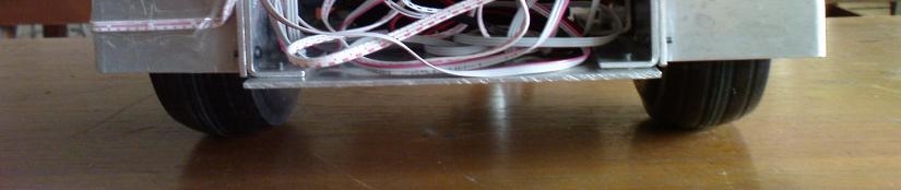
19 Tampak Depan Tampak Belakang


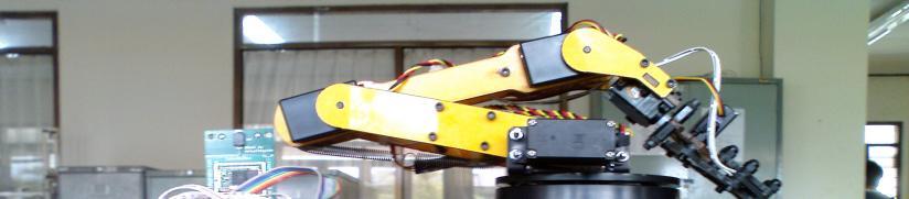


20 Tampak Samping Kiri Tampak Samping Kanan


21 Tampak Atas
LAMPIRAN A FOTO Radio Control Helikopter dan Pengendalinya
 LAMPIRAN A FOTO Radio Control Helikopter dan Pengendalinya Tampak Atas A-1 Tampak Depan A-2 Tampak Samping A-3 Tampak Belakang A-4 Pengendali A-5 LAMPIRAN B PROGRAM PADA MICROSOFT VISUAL BASIC 6 DAN PENGONTROL
LAMPIRAN A PROGRAM UTAMA ROBOT NOMOR 2
 LAMPIRAN A PROGRAM UTAMA ROBOT NOMOR 2 1: 2: 3: 4: 5: 6: 7: 8: 9: 10: 11: 12: 13: 14: 15: 16: 17: 18: 19: 20: 21: [Bioloid Premium]-Robot 2 v 2 22: 23: 24: 25: A-1 26: 27: 28: 29: 30: 31: 32: 33: 34: 35:
Lampiran. Universitas Sumatera Utara
 Lampiran LISTING PROGRAM #include #include // Declare your global variables here char buff[16]; unsigned int frekuensi,x; unsigned int detak; // External Interrupt 0 service routine
RANGKAIAN LENGKAP. Universitas Sumatera Utara
 RANGKAIAN LENGKAP Lampiran Program /***************************************************** This program was produced by the CodeWizardAVR V1.25.8 Professional Automatic Program Generator Copyright 1998-2007
LAMPIRAN. 1. Program Alat
 LAMPIRAN 1. Program Alat This program was produced by the CodeWizardAVR V2.03.4 Standard Automatic Program Generator Copyright 1998-2008 Pavel Haiduc, HP InfoTech s.r.l. http://www.hpinfotech.com Project
LAMPIRAN A. Universitas Sumatera Utara
 63 LAMPIRAN A Rangkaian Lengkap Perangkat Keras Rangkaian ini terdiri dari Rangkaian Power Supply (PSA), Mikrokontroller atmega8535, RFID Reader ID 12, Rangkaian Infra Merah Fotodioda, driver max232 dan
Gambar A-1 Foto alat prototype infrared thermometer
 LAMPIRAN A Foto Alat Gambar A-1 Foto alat prototype infrared thermometer A-1 LAMPIRAN A A-2 LAMPIRAN A Daftar Komponen yang digunakan Komponen Aktif Nama komponen Fungsi Jumlah AVR ATMega 8535 Mikrokontroler
LAMPIRAN A FOTO ALAT
 LAMPIRAN A FOTO ALAT Gambar A.1. Gambar robot mobil dilihat dari atas Gambar A.2. Gambar robot mobil dilihat dari depan Gambar A.3. Gambar robot mobil dilihat dari samping Gambar A.4. Gambar keseluruhan
// WRITE data to be written to EEPROM
 /***************************************************** This program was produced by the CodeWizardAVR V2.03.9 Evaluation Automatic Program Generator Copyright 1998-2008 Pavel Haiduc, HP InfoTech s.r.l.
Ali Karimpour Associate Professor Ferdowsi University of Mashhad
 AUTOMATIC CONTROL SYSTEMS Ali Karimpour Associate Professor Ferdowsi University of Mashhad Reference: Microcontroller Based Applied Digital Control Dogan Ibrahim, John Wiley & Sons Ltd, 2006 Liquid Level
LAMPIRAN A FOTO ROBOT BERKAKI ENAM
 LAMPIRAN A FOTO ROBOT BERKAKI ENAM A-1 A-2 LAMPIRAN B PROGRAM PADA PENGONTROL ATMEGA16 DAN ATTINY2313 B-1 1. Robot mampu berjalan sesuai dengan langkah dan arah yang dimasukkan melalui keypad. ATMEGA16
LAMPIRAN A. Foto Alat
 LAMPIRAN A Foto Alat A-1 A-2 Rangkaian Skematik PCB Sistem Monitoring Infus A-3 LAMPIRAN B Program pada Mikrokontroller AVR Atmega16...B-1 Program pada Borlan Delhpi 7.0...B-9 PROGRAM UTAMA /*****************************************************
LAMPIRAN. Program Keseluruhan Sistem Pengontrolan Level Air
 LAMPIRAN Program Keseluruhan Sistem Pengontrolan Level Air /***************************************************** This program was produced by the CodeWizardAVR V2.03.4 Standard Automatic Program Generator
LAMPIRAN A. Listing Program. Program pada Borland Delphi 7.0 A-1 Program pada CodeVisionAVR C Compiler A-6
 A Listing Program Program pada Borland Delphi 7.0 A-1 Program pada CodeVisionAVR C Compiler A-6 LISTING PROGRAM BORLAND DELPHI 7.0 Inisialisasi ==========================================================
Software Design Considerations, Narrative and Documentation
 Software Design Considerations, Narrative and Documentation Introduction The project under consideration is an automated shopping cart designed to follow a shopper around a simulated supermarket environment.
Getting Started With the Micro64
 1.0 Software Installation Getting Started With the Micro64 1.1 Installing the CodeVisionAVR C Compiler 1. Open the CodeVisionAVR Demo folder on the CD. 5. Click the Next button and the following window
LAMPIRAN A GAMBAR SISTEM
 LAMPIRAN A GAMBAR SISTEM SISTEM OBJEK TAMPAK DALAM SISTEM OBJEK TAMPAK LUAR SISTEM PENERIMA LAMPIRAN B PROGRAM AVR ATMEGA 128 /***************************************************** Chip type : ATmega128L
ECE477: Team 10 Software Design Considerations, Narrative, and Documentation
 TABLE OF CONTENTS 1 INTRODUCTION...2 1.1 MASTER DEVICE...2 1.2 SLAVE (SITE) DEVICE...2 1.3 CONNECTING BUS...2 2 MASTER DEVICE...3 2.1 SOFTWARE DESIGN CONSIDERATIONS...3 2.1.1 Memory Considerations...3
LAMPIRAN A List Program CodeVision Generato Data...A-1 List Program CodeVision Multiplexer...A-11 List Program CodeVision Demultiplexer...
 LAMPIRAN A List Program CodeVision Generato Data...A-1 List Program CodeVision Multiplexer...A-11 List Program CodeVision Demultiplexer...A-14 List Program Codevision Generator Data /****************************************
LAMPIRAN A LIST PROGRAM SERVER DAN CLIENT
 1 LAMPIRAN A LIST PROGRAM SERVER DAN CLIENT 2 KETERANGAN OBJEK KONTROL SERVER (VB.6) OBJEK PROPERTY SETTING Command1 Caption Exit Command2 Caption START Command3 Caption UP Command4 Caption DOWN Command5
Lampiran 1 Tabel data normalisasi lemari tabung LPG dari alat Konsentrasi Gas LPG Konsentrasi Gas
 52 Lampiran 1 Tabel data normalisasi lemari tabung LPG dari alat Konsentrasi Gas LPG Konsentrasi Gas Waktu (s) Data 1 (ppm) Data 2 (ppm) Data 3 (ppm) LPG Rata-rata (ppm) 10 2640,02 2725,35 2773,96 2713,11
Project : Version : Date : 11/04/2016 Author : Freeware, for evaluation and non-commercial use only Company : Comments:
 Lampiran 1 Listing program dari seluruh sistem. /***************************************************** This program was produced by the CodeWizardAVR V2.04.9 Evaluation Automatic Program Generator Copyright
// Voltage Reference: AREF pin #define ADC_VREF_TYPE ((0<<REFS1) (0<<REFS0) (0<<ADLAR))
 (0<<REFS0) (0<<ADLAR))") 44 Lampiran 1 Listing program dari seluruh sistem. /****************************************************** * This program was created by the CodeWizardAVR V3.12 Advanced Automatic Program Generator Copyright
44 Lampiran 1 Listing program dari seluruh sistem. /****************************************************** * This program was created by the CodeWizardAVR V3.12 Advanced Automatic Program Generator Copyright
How2Use DT-AVR ATMEGA168 BMS. By: IE Team. Picture 1 The layout of DT-AVR ATMEGA168 BMS
 DT-AVR ATMEGA168 BMS Application Note By: IE Team This Application Note (AN) serves as a tutorial of how to use the DT-AVR ATMEGA168 Bootloader Micro System along with its supplementary software. The layout
Set of pulse decoding algorithms for quadrature rotary and linear encoders*
 version 1.2 Set of pulse decoding algorithms for quadrature rotary and linear encoders* (*) Algorithms are likely platform nonindependent in performance comparison. However results are based to the Atmel
Universitas Sumatera Utara
 55 Lampiran 1. Konfigurasi Program Menghitung Data Komputer (Bahasa C) pada Mikro /******************************************************* This program was created by the CodeWizardAVR V2.60 Standard Automatic
Lampiran I. Rangkaian Lengkap Alat. Universitas Sumatera Utara
 Lampiran I Rangkaian Lengkap Alat Lampiran II Program Pada Alat /***************************************************** This program was produced by the CodeWizardAVR V2.04.9 Evaluation Automatic Program
LAMPIRAN A. Universitas Sumatera Utara
 LAMPIRAN A Program CODEVISIONAVR Untuk program mikrokontroler pada Robot /***************************************************** Date : 8/24/2014 Chip type : ATmega16 Program type : Application AVR Core
LAMPIRAN A. I. Gambar alat percobaan I.1. Power supply. 1. Rangkaian sekunder 2. Dioda. 3. Heatsink 4. Power supply (keseluruhan)
") 100 I. Gambar alat percobaan I.1. Power supply LAMPIRAN A 1. Rangkaian sekunder 2. Dioda 3. Heatsink 4. Power supply (keseluruhan) 101 I.2 Gambar bagian bagian alat pemanas induksi 1. Kumparan Solenoide
100 I. Gambar alat percobaan I.1. Power supply LAMPIRAN A 1. Rangkaian sekunder 2. Dioda 3. Heatsink 4. Power supply (keseluruhan) 101 I.2 Gambar bagian bagian alat pemanas induksi 1. Kumparan Solenoide
Appendix to Vehicle Automation and Security (Matthew Grojean & Nathan Hart) Nathan Hart Professor Zalewski 04/25/2014
 Nathan Hart Professor Zalewski 04/25/2014") Page 1 Appendix to Vehicle Automation and Security (Matthew Grojean & Nathan Hart) Nathan Hart Professor Zalewski 04/25/2014 A1. Overview of Previous Project The goal of the original Vehicle Automation
Page 1 Appendix to Vehicle Automation and Security (Matthew Grojean & Nathan Hart) Nathan Hart Professor Zalewski 04/25/2014 A1. Overview of Previous Project The goal of the original Vehicle Automation
8-bit Microcontroller. Application Note. AVR033: Getting Started with the CodeVisionAVR C Compiler
 AVR033: Getting Started with the CodeVisionAVR C Compiler Features Installing and Configuring CodeVisionAVR to Work with the Atmel STK500 Starter Kit and AVR Studio Debugger Creating a New Project Using
Serial Compact Flash Serial CF Card Module User Manual
 CUBLOC Peripheral Serial Compact Flash Serial Card Module User Manual 3. Specifications Model -COM5 -COM3 Voltage 4.5~5.5V 2.7~5.5V - 115200 bps: 20KB/s - 115200 bps: 15KB/s Read Speed - 9600 bps: 6KB/s
8-bit Microcontroller. Application Note. AVR033: Getting Started with the CodeVisionAVR C Compiler
 AVR033: Getting Started with the CodeVisionAVR C Compiler Features Installing and Configuring CodeVisionAVR to Work with the Atmel STK500 Starter Kit and AVR Studio Debugger Creating a New Project Using
J. Basic. Appl. Sci. Res., 3(2s) , , TextRoad Publication
 , , TextRoad Publication") 2013, TextRoad Publication ISSN 2090-4304 Journal of Basic and Applied Scientific Research www.textroad.com Designing and Construction of the Transceiver System by Using a New Generation of Telecommunication
2013, TextRoad Publication ISSN 2090-4304 Journal of Basic and Applied Scientific Research www.textroad.com Designing and Construction of the Transceiver System by Using a New Generation of Telecommunication
LAMPIRAN A /*******************************************************
 42 Program pada mikrokontroler LAMPIRAN A /******************************************************* This program was created by the CodeWizardAVR V3.12 Advanced Project : gelombang Version : Revisi 4 Date
How2Use DT-AVR ATMEGA128L BMS. Oleh: IE Team. Picture 1 The layout of DT-AVR ATMEGA128L BMS
 DT-AVR ATMEGA128L BMS Application Note Oleh: IE Team This Application Note (AN) serves as a tutorial of how to use the DT-AVR ATMEGA128L Bootloader Micro System along with its supplementary software. The
Microcomputer/Controller Featuring the ATmega64 or the ATmega128
 Microcomputer/Controller Featuring the ATmega64 or the ATmega128 FEATURES Small size complete computer/controller with I/O less than 1.5 cubic inches (1.5 x 2.1 x 0.52 ) Low power only 275 mw typical Dual
AN703. Micro64/128. Accessing the 36k of SRAM 12/3/04
 AN703 Micro64/128 Accessing the 36k of SRAM 12/3/04 Introduction: Micro64/128 has a total of 36k of SRAM. 4 k of SRAM is built into the processor an additional 32k of SRAM is available inside the Micro64/128
W.E.S.L.E.Y. Waste Eliminating System for Lazy Engineering Youths. Final Report December 9, 2003 John Mercado
 Waste Eliminating System for Lazy Engineering Youths Final Report December 9, 2003 John Mercado Table of Contents: Abstract... 3 Executive Summary... 3 Introduction... 3 Integrated Systems... 4 Mobile
Embedded Systems and Software
 Embedded Systems and Software Lab 6 Considerations Lab 6 Considerations, Slide 1 Big Picture Connect to internal ADC + 0-5 V - Sensor To COM port on PC LCD RTC Optional: LCD display Lab 6 Considerations,
Introduction to the MC9S12 Hardware Subsystems
 Setting and clearing bits in C Using pointers in C o Program to count the number of negative numbers in an area of memory Introduction to the MC9S12 Hardware Subsystems o The MC9S12 timer subsystem Operators
Introduction to Embedded Systems
 Stefan Kowalewski, 4. November 25 Introduction to Embedded Systems Part 2: Microcontrollers. Basics 2. Structure/elements 3. Digital I/O 4. Interrupts 5. Timers/Counters Introduction to Embedded Systems
ADC: Analog to Digital Conversion
 ECE3411 Fall 2015 Lecture 5a. ADC: Analog to Digital Conversion Marten van Dijk, Syed Kamran Haider Department of Electrical & Computer Engineering University of Connecticut Email: {vandijk, syed.haider}@engr.uconn.edu
ADC: Analog to Digital Conversion
 ECE3411 Fall 2015 Lecture 5b. ADC: Analog to Digital Conversion Marten van Dijk, Syed Kamran Haider Department of Electrical & Computer Engineering University of Connecticut Email: {vandijk, syed.haider}@engr.uconn.edu
COMP2121: Microprocessors and Interfacing
 Lecture 19: Interrupts II http://www.cse.unsw.edu.au/~cs2121 Lecturer: Hui Wu Session 1, 2006 Overview AVR Interrupts Interrupt Vector Table System Reset Watchdog Timer Timer/Counter0 Interrupt Service
Programming Microcontroller Assembly and C
 Programming Microcontroller Assembly and C Course Number CLO : 2 Week : 5-7 : TTH2D3 CLO#2 Student have the knowledge to create basic programming for microcontroller [C3] Understand how to program in Assembly
The MC9S12 Timer Output Compare Function Making an event happen at specific time on the HC12 The MC9S12 Output Compare Function
 The MC9S12 Timer Output Compare Function Making an event happen at specific time on the HC12 The MC9S12 Output Compare Function o Registers used to enable the output compare function o Using the MC9S12
Capturing the Time of an External Event Input Capture Subsystem
 Capturing the Time of an External Event Input Capture Subsystem One way to determine the time of an external event is to wait for the event to occur, the read the TCNT register: For example, to determine
 Features 2.4 GHz Carrier Frequency RS232 UART interface with variable baud rate Input supply voltage: 5V to 12V 255 possible Channels frequencies (0 to 255) Programmable Device Address (255 per channel)
School of Electrical, Computer and Telecommunications Engineering University of Wollongong Australia
 ECTE333 s schedule ECTE333 Lecture 9 -Timers School of Electrical, Computer and Telecommunications Engineering University of Wollongong Australia Week Lecture (2h) Tutorial (h) Lab (2h) L7: C programming
MCU: Interrupts and Timers. Ganesh Pitchiah
 MCU: Interrupts and Timers Ganesh Pitchiah What s an MCU? Frequency = 8 MHz Time Period = 1/f = 0.125 us Code for Switching LED int a; voltage while(1) { a = PINA.0; input) If (a==1) PORTA.1=1; else PORTA.1=0;
Final Design Report. Team Name: No Rest for the Weary
 EEL 4924 Electrical Engineering Design (Senior Design) Final Design Report 4 August 2009 Project Title: SLEEP Team Name: No Rest for the Weary Team Members: Renard Sumlar lrsum825@ufl.edu Brad Bromlow
SwampBoard.com Bot. Foley Ma Spring 2006 IMDL
 SwampBoard.com Bot Foley Ma Spring 2006 IMDL Table of Contents Title Page Page 1 Table of Contents Page 2 Abstract Page 3 Executive Summary Page 4 Introduction Page 5 Integrated Systems Page 6..7 Mobile
How to use RFpro in Packet Mode
 How to use RFpro in Packet Mode Jumper Setting Priority Jumper J1 à Configuration Mode Jumper à Higher Priority Jumper J2 à Packet Mode Jumper à Lower Priority When both the jumpers are connected, by default,
The Atmel ATmega168A Microcontroller
 Ming Hsieh Department of Electrical Engineering EE 459Lx - Embedded Systems Design Laboratory The Atmel ATmega168A Microcontroller by Allan G. Weber 1 Introduction The Atmel ATmega168A is one member of
ATMega16 AVR AVR AVR DIP. (in-circiut programming) desktop MOSI MOSIT. AVRProg. header. (toggle)
 desktop MOSI MOSIT. AVRProg. header. (toggle)") ATMega16 AVR AVR ATMega16 AVR AVR AVR DIP (in-circiut programming) desktop MOSI GND SK MISO MOSIT Ω Dontronic SK MISO AVRProg AVR109 JTAGIEII STK500 AVR header AVRProg clock I/O (toggle) clock GND V ATMega16
ATMega16 AVR AVR ATMega16 AVR AVR AVR DIP (in-circiut programming) desktop MOSI GND SK MISO MOSIT Ω Dontronic SK MISO AVRProg AVR109 JTAGIEII STK500 AVR header AVRProg clock I/O (toggle) clock GND V ATMega16
The Atmel ATmega328P Microcontroller
 Ming Hsieh Department of Electrical Engineering EE 459Lx - Embedded Systems Design Laboratory 1 Introduction The Atmel ATmega328P Microcontroller by Allan G. Weber This document is a short introduction
Automatic Gate Prototype Based on Microcontroller of Atmel ATMega16
 Journal of Electrical Technology UMY (JET-UMY), Vol. 1, No. 2, June 2017 ISSN 2550-1186 e-issn 2580-6823 Automatic Gate Prototype Based on Microcontroller of Atmel ATMega16 Anna Nur Nazilah Chamim *1,
Topic 11: Timer ISMAIL ARIFFIN FKE UTM SKUDAI JOHOR
 Topic 11: Timer ISMAIL ARIFFIN FKE UTM SKUDAI JOHOR Introduction Timer s objective Timer features Timer Registers - Understand function of each bit Initialization Introduction o In micro-p, we use counter
WEATHER STATION WITH SERIAL COMMUNICATION
 WEATHER STATION WITH SERIAL COMMUNICATION Written by: Wenbo Ye, Xiao Qu, Carl-Wilhelm Igelström FACULTY OF ENGINEERING, LTH Digital and Analogue Projects EITF11 Contents Introduction... 2 Requirements...
12.1. Unit 12. Exceptions & Interrupts
 12.1 Unit 12 Exceptions & Interrupts 12.2 Disclaimer 1 This is just an introduction to the topic of interrupts. You are not meant to master these right now but just start to use them We will cover more
The MC9S12 Timer Input Capture Function
 The MC9S12 Timer Input Capture Function o Capturing the time of an external event o The MC9S12 Input Capture Function o Registers used to enable the Input Capture Function o Using the MC9S12 Input Capture
INTERRUPT, TIMER/COUNTER. KONKUK UNIV. VLSI Design Lab. LSI Design Lab
 INTERRUPT, TIMER/COUNTER KONKUK UNIV. V. 1 INTERRUPT 의개요 외부의요구에의해서현재실행중인프로그램을일시중지하고보다시급한작업을먼저수행한후다시원래의프로그램으로복귀하는것. EX) 스타를하다가택배가오면스타를일시중지하고택배를받은후다시스타를진행함. Interrupt 방식 : 택배아저씨가초인종을눌러줌. Polling 방식 : 택배아저씨가오는지일정시간간격으로살펴봄.
EE 308 Spring A software delay. To enter a software delay, put in a nested loop, just like in assembly.
 More on Programming the 9S12 in C Huang Sections 5.2 through 5.4 Introduction to the MC9S12 Hardware Subsystems Huang Sections 8.2-8.6 ECT_16B8C Block User Guide A summary of MC9S12 hardware subsystems
C Programming Language
 C Programming Language Advantages over assembly language for microcontrollers: More portable Math functions Readability Maintainability Editing C End-of-line ignored Use line breaks/tabs/indent for readability
Timers and Interrupts. Mark Neil - Microprocessor Course
 Timers and Interrupts 1 Example Product: Signal Generator A Signal Generator should be programmable. A user can use the the LCD display and the keyboard to change the: Frequency scale Amplitude scale Offset
ATmega Interrupts. Reading. The AVR Microcontroller and Embedded Systems using Assembly and C) by Muhammad Ali Mazidi, Sarmad Naimi, and Sepehr Naimi
 by Muhammad Ali Mazidi, Sarmad Naimi, and Sepehr Naimi") 1 P a g e ATmega Interrupts Reading The AVR Microcontroller and Embedded Systems using Assembly and C) by Muhammad Ali Mazidi, Sarmad Naimi, and Sepehr Naimi Chapter 10: AVR Interrupt Programming in Assembly
1 P a g e ATmega Interrupts Reading The AVR Microcontroller and Embedded Systems using Assembly and C) by Muhammad Ali Mazidi, Sarmad Naimi, and Sepehr Naimi Chapter 10: AVR Interrupt Programming in Assembly
University of Florida EEL 4744 Spring 2014 Dr. Eric M. Schwartz Department of Electrical & Computer Engineering 1 April Apr-14 9:03 AM
 Page 1/15 Exam 2 Instructions: Turn off cell phones beepers and other noise making devices. BEAT UCONN! Show all work on the front of the test papers. If you need more room make a clearly indicated note
Lecture 14. Ali Karimpour Associate Professor Ferdowsi University of Mashhad
 Lecture 14 AUTOMATIC CONTROL SYSTEMS Ali Karimpour Associate Professor Ferdowsi University of Mashhad Lecture 4 The AVR Microcontroller Introduction to AVR CISC (Complex Instruction Set Computer) Put as
Relational Operators. > greater than < less than >= greater than or equal to <= less than or equal to <> not equal to = equal to
 Relational Operators > greater than < less than >= greater than or equal to
Topic 11: Interrupts ISMAIL ARIFFIN FKE UTM SKUDAI JOHOR
 Topic 11: Interrupts ISMAIL ARIFFIN FKE UTM SKUDAI JOHOR Objectives To become familiar with interrupts on the AVR Maskable and non-maskable Initialization Triggers To develop interrupt service routines
 Overview RFSv4.3 is a RF module providing easy and flexible wireless data transmission between devices. It is based on AVR Atmega8 with serial output which can be interfaced directly to PC. Features 2.4
Burglar Alarm Final Report
 Burglar Alarm Submitted By: Brandon Maciel, Linda Thompson, Bradford Savage ETEE3255 Lab VII Instructor: Barry Sherlock Date Due: November 18 th, 2010 Abstract 1 The purpose of this project was to design,
LAMPIRAN. Universitas Sumatera Utara
 LAMPIRAN Program Untuk Mengetes Huruf R Pada Matriks 8x8 /******************************************************* This program was created by the CodeWizardAVR V3.09 Standard Automatic Program Generator
INTERRUPTS in microprocessor systems
 INTERRUPTS in microprocessor systems Microcontroller Power Supply clock fx (Central Proccesor Unit) CPU Reset Hardware Interrupts system IRQ Internal address bus Internal data bus Internal control bus
Interrupts & Interrupt Service Routines (ISRs)
") ECE3411 Fall 2015 Lecture 2c. Interrupts & Interrupt Service Routines (ISRs) Marten van Dijk, Syed Kamran Haider Department of Electrical & Computer Engineering University of Connecticut Email: vandijk,
ECE3411 Fall 2015 Lecture 2c. Interrupts & Interrupt Service Routines (ISRs) Marten van Dijk, Syed Kamran Haider Department of Electrical & Computer Engineering University of Connecticut Email: vandijk,
UART: Universal Asynchronous Receiver & Transmitter
 ECE3411 Fall 2015 Lecture 2a. UART: Universal Asynchronous Receiver & Transmitter Marten van Dijk, Syed Kamran Haider Department of Electrical & Computer Engineering University of Connecticut Email: {vandijk,
CN310 Microprocessor Systems Design
 CN310 Microprocessor Systems Design Microcontroller Nawin Somyat Department of Electrical and Computer Engineering Thammasat University Outline Course Contents 1 Introduction 2 Simple Computer 3 Microprocessor
Interrupt vectors for the 68HC912B32. The interrupt vectors for the MC9S12DP256 are located in memory from 0xFF80 to 0xFFFF.
 Interrupts The Real Time Interrupt Interrupt vectors for the 68HC912B32 The interrupt vectors for the MC9S12DP256 are located in memory from 0xFF80 to 0xFFFF. These vectors are programmed into Flash EEPROM
Embedded Systems and Software. Serial Communication
 Embedded Systems and Software Serial Communication Slide 1 Using RESET Pin on AVRs Normally RESET, but can be configured via fuse setting to be general-purpose I/O Slide 2 Disabling RESET Pin on AVRs Normally
19.1. Unit 19. Serial Communications
 9. Unit 9 Serial Communications 9.2 Serial Interfaces Embedded systems often use a serial interface to communicate with other devices. Serial implies that it sends or receives one bit at a time. µc Device
Embedded Systems and Software
 Embedded Systems and Software Serial Communication Serial Communication, Slide 1 Lab 5 Administrative Students should start working on this LCD issues Caution on using Reset Line on AVR Project Posted
COMP2121: Microprocessors and Interfacing
 COMP2121: Microprocessors and Interfacing Lecture 25: Serial Input/Output (II) Overview USART (Universal Synchronous and Asynchronous serial Receiver and Transmitter) in AVR http://www.cse.unsw.edu.au/~cs2121
EE318 Electronic Design Lab, Project Report, EE Dept, IIT Bombay, April GPS Tracker. Group No: B11
 EE318 Electronic Design Lab, Project Report, EE Dept, IIT Bombay, April 2009 GPS Tracker Group No: B11 B.V. Sesha Pavan Srinadh (06007038) Mayank Manjrekar (06007036)
INTERFACING HARDWARE WITH MICROCONTROLLER
 INTERFACING HARDWARE WITH MICROCONTROLLER P.Raghavendra Prasad Final Yr EEE What is a Microcontroller? A microcontroller (or MCU) is acomputer-on-a-chip. It is a type of microprocessor emphasizing self-
Flow Chart. The diagrammatic representation shows a solution to a given problem.
 low Charts low Chart A flowchart is a type of diagram that represents an algorithm or process, showing the steps as various symbols, and their order by connecting them with arrows. he diagrammatic representation
Timer0..Timer3. Interrupt Description Input Conditions Enable Flag
 Timer0..Timer3 Timers are pretty useful: likewise, Microchip provides four different timers for you to use. Like all interrupts, you have to Enable the interrupt, Set the conditions of the interrupt, and
Digital and Analogue Project Report
 EITF 040 Digital and Analogue Project Report Group 6 Fida Saidani Qinghua Liu March, 2013 1 Abstract The aim of this project is to build an electronic device that makes use of the law of light reflection,
Interrupt Controlled UART
 AVR306 Design Note: Using the AVR UART in C Features Setup and Use the AVR UART Code Examples for Polled and Interrupt Controlled UART Compact Code C-Code Included for AT90S8515 Description This application
UNIVERSITY OF CONNECTICUT. ECE 3411 Microprocessor Application Lab: Fall Quiz II
 Department of Electrical and Computing Engineering UNIVERSITY OF CONNECTICUT ECE 3411 Microprocessor Application Lab: Fall 2015 Quiz II There are 5 questions in this quiz. There are 9 pages in this quiz
Arduino. (Digital-to-Analog Converter D/A D2A) (Digital to Analog Conversion) 3. (Analog to Digital conversion)
 (Digital to Analog Conversion) 3. (Analog to Digital conversion)") Arduino 1. 2. (Digital to Analog Conversion) 3. (Analog to Digital conversion) 1 2 Analog to Digital Converter (ADC) (Digital-to-Analog Converter D/A D2A) Digital to Analog Converter (DAC) 3 4 DAC Binary
Arduino 1. 2. (Digital to Analog Conversion) 3. (Analog to Digital conversion) 1 2 Analog to Digital Converter (ADC) (Digital-to-Analog Converter D/A D2A) Digital to Analog Converter (DAC) 3 4 DAC Binary
CprE 288 Introduction to Embedded Systems (Timers/Input Capture) Instructors: Dr. Phillip Jones
 Instructors: Dr. Phillip Jones") CprE 288 Introduction to Embedded Systems (Timers/Input Capture) Instructors: Dr. Phillip Jones 1 Announcements HW 4, Due Wed 6/13 Quiz 5 (15 min): Wed 6/13, Textbook reading: Section 9.1, 9.2 (your one-side
CprE 288 Introduction to Embedded Systems (Timers/Input Capture) Instructors: Dr. Phillip Jones 1 Announcements HW 4, Due Wed 6/13 Quiz 5 (15 min): Wed 6/13, Textbook reading: Section 9.1, 9.2 (your one-side
Software Documentation
 QS Series Master Development System Software Documentation Introduction The software included with the MDEV-USB-QS Master Development Kit is a quick and easy way to test the features of the QS Series USB
HC12 Built-In Hardware
 HC12 Built-In Hardware The HC12 has a number of useful pieces of hardware built into the chip. Different versions of the HC12 have slightly different pieces of hardware. We are using the MC68HC912B32 chip
Interrupts and Serial Communication on the PIC18F8520
 Interrupts and Serial Communication on the PIC18F8520 Kyle Persohn COEN 4720 Fall 2011 Marquette University 6 October 2011 Outline 1 Background Serial Communication PIC18 Interrupt System 2 Customizing
EE 308: Microcontrollers
 EE 308: Microcontrollers Interrupts Aly El-Osery Electrical Engineering Department New Mexico Institute of Mining and Technology Socorro, New Mexico, USA March 1, 2018 Aly El-Osery (NMT) EE 308: Microcontrollers
Serial Communications
 1 Serial Interfaces 2 Embedded systems often use a serial interface to communicate with other devices. Serial Communications Serial implies that it sends or receives one bit at a time. Serial Interfaces
PROJECT ELECTRONIC CONTROL GAS INJECTION SYSTEM
 PROJECT ELECTRONIC CONTROL GAS INJECTION SYSTEM SOURCE CODE VISUAL BASIC Dim WR As Boolean Dim pw Dim data Dim oxg Public index1 Dim index2 Dim k Dim u Dim refd Dim datar1$(1000, 9) Dim c_data Dim A$(10)
RS232.C An Interrupt driven Asyncronous Serial Port
 /***************************************************************************/ /* RS232.C An Interrupt driven Asyncronous Serial Port */ /* Date : 06/03/2002 */ /* Purpose : Asyncronous Transmitter & Receiver
My Muzik 1.0. MP3 Player using (VNC1L/VS1033/AVR8) User Manual (Rev 1.0) OrientNDT Co.,LTD
 User Manual (Rev 1.0) OrientNDT Co.,LTD") My Muzik 1.0 MP3 Player using (VNC1L/VS1033/AVR8) User Manual (Rev 1.0) 2009.3 OrientNDT Co.,LTD http://max0.com 1 Category Page 1.What is My Muzik 1.0? 1.1 Introduction... 3 1.2 Function Diagram... 4
My Muzik 1.0 MP3 Player using (VNC1L/VS1033/AVR8) User Manual (Rev 1.0) 2009.3 OrientNDT Co.,LTD http://max0.com 1 Category Page 1.What is My Muzik 1.0? 1.1 Introduction... 3 1.2 Function Diagram... 4