Ali Karimpour Associate Professor Ferdowsi University of Mashhad
|
|
|
- Brendan Hodge
- 5 years ago
- Views:
Transcription
1 AUTOMATIC CONTROL SYSTEMS Ali Karimpour Associate Professor Ferdowsi University of Mashhad Reference: Microcontroller Based Applied Digital Control Dogan Ibrahim, John Wiley & Sons Ltd, 2006
2 Liquid Level Digital Control System: A Case Study Topics to be covered include: Design of controller in time domain. 2
3 A typical liquid level control system 3


4 A typical liquid level control system Schematic of the system 4

5 System Model 5
6 Series Compensation Structure جبران سازي سري Ziegler-Nichols Design for PID Controller This procedure is only valid for open loop stable plants. Open-Loop Tuning Closed-Loop Tuning According to Ziegler and Nichols, the open-loop transfer function of a system can be approximated with time delay and single-order system, i.e. 6
7 Ziegler-Nichols Open-Loop Case طراحی زیگلر نیکولز حالت حلقه باز For open-loop tuning, we first find the plant parameters by applying a step input to the open-loop system. The plant parameters K, TD and T1 are then found from the result of the step test as shown in Figure. 7
8 Identification of System Model 5*200/256=3.906 v 2.5*3.906=9.76 v 200 8
9 Microcontroller program to send a step to D/A For program the Microcontroller we just need to: 1- Define PORTB as Enable DAC 3- Disable DAC That s all 9
10 Identification of System Model Gs is transfer function of tank+amplifier 10
11 Controller Design and Implementation 11 Controller Implementation s K K s e s u s D i p s K e s se K s su i p t K e dt t de K dt t du i p t K e T T t e t e K T T t u t u i p T t e K t e TK K T t u t u p i p 1 1 t e z K t e TK K t u z t u p i p 1 1 z TK K z e z u z D i p
12 Series Compensation Structure جبران سازي سري Continues block diagram Digital block diagram +z.o.h. 12
13 Sampling period Digital block diagram +z.o.h. First of all we need sampling period Time constant is 31 so we must consider T<3.1, we choose
14 System 14
15 Complete system 15

16 16
17 Microcontroller program to implement the controller Chip selection Project information Port configuration External interrupts LCD configuration ADC configuration Timers configuration Main program Controller output calculation Code WizardAVR Code WizardAVR Code WizardAVR Code WizardAVR Code WizardAVR Code WizardAVR Code WizardAVR By yourself By yourself 17


18 Chip selection Chip selection Tools Code WizardAVR Code WizardAVR 18

19 Project information /***************************************************** This program was produced by the CodeWizardAVR V Evaluation Automatic Program Generator Copyright Pavel Haiduc, HP InfoTech s.r.l. Project : Level Control Version : 1 Date : 2012/12/27 Author : Karimpour Company : Ferdowsi University of Mashhad Comments: This is a simple example for class. Chip type : ATmega16 Program type : Application AVR Core Clock frequency: MHz Memory model : Small External RAM size : 0 Data Stack size : 256 *****************************************************/ 19 #include <mega16.h>

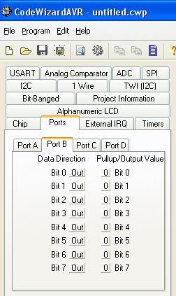


20 Port configuration 20
21 Port configuration void mainvoid // Input/Output Ports initialization // Port A initialization // Func7=In Func6=In Func5=In Func4=In Func3=In Func2=In Func1=In Func0=In // State7=T State6=T State5=T State4=T State3=T State2=T State1=T State0=T PORTA=0x00; DDRA=0x00; // Port B initialization // Func7=Out Func6=Out Func5=Out Func4=Out Func3=Out Func2=Out Func1=Out Func0=Out // State7=0 State6=0 State5=0 State4=0 State3=0 State2=0 State1=0 State0=0 PORTB=0x00; DDRB=0xFF; // Port C initialization // Func7=In Func6=In Func5=In Func4=In Func3=In Func2=In Func1=In Func0=Out // State7=T State6=T State5=T State4=T State3=T State2=T State1=T State0=0 PORTC=0x00; DDRC=0x01; // Port D initialization // Func7=In Func6=In Func5=In Func4=In Func3=In Func2=In Func1=In Func0=In // State7=T State6=T State5=T State4=T State3=T State2=T State1=T State0=T PORTD=0x00; DDRD=0x00; 21
![External interrupt configuration // void External mainvoid Interrupt 0 service routine interrupt [EXT_INT0] void ext_int0_isrvoid.](/docs-images/83/88003469/images/22-2.jpg ". // Place External your Interrupts code here initialization // INT0: On // INT0 Mode: Low level // External Interrupt 1 service routine // INT1: On interrupt [EXT_INT1] void ext_int1_isrvoid // INT1")
22 External interrupt configuration // void External mainvoid Interrupt 0 service routine interrupt [EXT_INT0] void ext_int0_isrvoid.. // Place External your Interrupts code here initialization // INT0: On // INT0 Mode: Low level // External Interrupt 1 service routine // INT1: On interrupt [EXT_INT1] void ext_int1_isrvoid // INT1 Mode: Low level // INT2: Off // Place your code here GICR =0xC0; MCUCR=0x00; MCUCSR=0x00; GIFR=0xC0; // Global enable interrupts #asm"sei 22

23 LCD configuration // Alphanumeric LCD Module functions #include <alcd.h> 23 void mainvoid.. // Alphanumeric LCD initialization // Connections specified in the // Project Configure C Compiler Libraries Alphanumeric LCD menu: // RS - PORTC Bit 1 // RD - PORTC Bit 2 // EN - PORTC Bit 3 // D4 - PORTC Bit 4 // D5 - PORTC Bit 5 // D6 - PORTC Bit 6 // D7 - PORTC Bit 7 // Characters/line: 16 lcd_init16; while 1 // Place your code here

24 ADC configuration #include <delay.h> void mainvoid #define ADC_VREF_TYPE 0x40... // Read ADC the initialization AD conversion result unsigned // ADC Clock char frequency: read_adcunsigned char khz adc_input // ADC Voltage Reference: AVCC pin ADMUX=adc_input // ADC Auto Trigger Source: ADC_VREF_TYPE Free Running & 0xff; // ADMUX=ADC_VREF_TYPE Delay needed for the stabilization & 0xff; of the ADC input voltage delay_us10; ADCSRA=0xA5; // SFIOR&=0x1F; Start the AD conversion ADCSRA =0x40; while 1 // Wait for the AD conversion to complete while // Place ADCSRA your code & 0x10==0; here ADCSRA =0x10; return ADCH; 24
25 Timers configuration // Timer 0 overflow interrupt service routine interrupt [TIM0_OVF] void timer0_ovf_isrvoid // Place your code here void mainvoid // Timer/Counter 0 initialization // Clock source: System Clock // Clock value: khz // Mode: Normal top=0xff // OC0 output: Disconnected TCCR0=0x04; TCNT0=0x00; OCR0=0x00; // Timers/Counters Interrupts initialization TIMSK=0x01; // Global enable interrupts #asm"sei" 25
26 Total Program from CodeWizardAVR #include <mega16.h> #include <delay.h> #include <alcd.h> interrupt [EXT_INT0] void ext_int0_isrvoid // Place your code here interrupt [EXT_INT1] void ext_int1_isrvoid // Place your code here // Timer 0 overflow interrupt service routine interrupt [TIM0_OVF] void timer0_ovf_isrvoid // Place your code here #define ADC_VREF_TYPE 0x40 unsigned int read_adcunsigned char adc_input ADMUX=adc_input ADC_VREF_TYPE & 0xff; delay_us10; ADCSRA =0x40; while ADCSRA & 0x10==0; ADCSRA =0x10; return ADCW; 26
27 Total Program from CodeWizardAVR void mainvoid // Declare your local variables here PORTA=0x00; DDRA=0x00; PORTB=0x00; DDRB=0xFF; PORTC=0x00; DDRC=0x01; PORTD=0x00; DDRD=0x00; TCCR0=0x04; TCNT0=0x00; OCR0=0x00; TCCR1A=0x00; TCCR1B=0x00; TCNT1H=0x00; TCNT1L=0x00; ICR1H=0x00; ICR1L=0x00; OCR1AH=0x00; OCR1AL=0x00; OCR1BH=0x00; OCR1BL=0x00; ASSR=0x00; TCCR2=0x00; TCNT2=0x00; OCR2=0x00; GICR =0xC0; MCUCR=0x00; MCUCSR=0x00; GIFR=0xC0; TIMSK=0x01; UCSRB=0x00; ACSR=0x80; SFIOR=0x00; ADMUX=ADC_VREF_TYPE & 0xff; ADCSRA=0xA5; SFIOR&=0x1F; SPCR=0x00; TWCR=0x00; lcd_init16; // Global enable interrupts #asm"sei" while 1 // Place your code here 27
28 // Reinitialize Timer 0 value TCNT0=0x64; time_set++; if time_set ==10 time_set = 0; yk // Controller = read_adc0; update must be here yk = yk *5000 / 1024; // convert ADC ek=ref-yk; uk = pk_1+kp+ki*ti* ek; uk = uk * 256/5000 ; if uk >255 uk_im = 255; else uk_im = unsigned char uk ; PORTB = uk_im ; PORTC.0 = 1 ; // write to D/A converter PORTC.0 = 0 ; pk_1 = uk-kp*ek ; u t u t T K e t T K TK e t p p Setting Timer i 28 // Timer 0 overflow interrupt service routine interrupt [TIM0_OVF] void timer0_ovf_isrvoid // Place your code here void Ts=0.1 mainvoid // Timer Timer/Counter counts cycle. initialization // Clock source: System Clock // Clock Clock of value: timer is khz Hz. // Mode: Normal top=0xff // Every OC0 156 output: counts Disconnected = 0.01 Sec. TCCR0=0x04; So 10 times of counter = 0.1 Sec. TCNT0=0x64; TCNT0=0x00; OCR0=0x00; So =156. // Start Timers/Counters of timer is 100 or Interrupts 0x64 in hex initialization TIMSK=0x01; // Global enable interrupts #asm"sei"
29 External interrupt program // External Interrupt 0 service routine interrupt [EXT_INT0] void ext_int0_isrvoid // ref++; Place your code here itoaref,ch; lcd_clear; lcd_putsch; // External Interrupt 1 service routine interrupt [EXT_INT1] void ext_int1_isrvoid // ref--; Place your code here itoaref,ch; lcd_clear; lcd_putsch; 29
30 Parameter Definition and Initial Values #include <stdlib.h> unsigned int time_set = 0; int ref= 2280; float kp, ki, pk_1,ek,yk, uk, T; unsigned char uk_im ; char ch[20];. kp =279.0; T= 0.1 ; ki=42.3; pk_1 = 0; PORTC.0 = 0 ; // disable write D/A itoaref,ch; lcd_putsch;while 1 // Place your code here 30
31 Total Program of System /***************************************************** This program was produced by the CodeWizardAVR V Evaluation Automatic Program Generator Copyright Pavel Haiduc, HP InfoTech s.r.l. Project : Level Control Version : 1 Date : 2012/12/30 Author : Freeware, for evaluation and non-commercial use only Company : Ferdowsi University of Mashhad Comments: This is a simple example for lecture#16. Chip type : ATmega16 Program type : Application AVR Core Clock frequency: MHz Memory model : Small External RAM size : 0 Data Stack size : 256 *****************************************************/ 31
32 Total Program of System #include <mega16.h> #include <delay.h> #include <alcd.h> #include <stdlib.h> unsigned int time_set = 0; int ref= 2280; float kp, ki, pk_1,ek,yk, uk, T; unsigned char uk_im ; char ch[20]; // Alphanumeric LCD Module functions #define ADC_VREF_TYPE 0x40 // Read the AD conversion result unsigned int read_adcunsigned char adc_input ADMUX=adc_input ADC_VREF_TYPE & 0xff; // Delay needed for the stabilization of the ADC input voltage delay_us10; // Start the AD conversion ADCSRA =0x40; // Wait for the AD conversion to complete while ADCSRA & 0x10==0; ADCSRA =0x10; return ADCW; 32
33 Total Program of System // External Interrupt 0 service routine interrupt [EXT_INT0] void ext_int0_isrvoid // Place your code here ref--; itoaref,ch; lcd_clear; lcd_putsch; // External Interrupt 1 service routine interrupt [EXT_INT1] void ext_int1_isrvoid // Place your code here ref++; itoaref,ch; lcd_clear; lcd_putsch; // Timer 0 overflow interrupt service routine interrupt [TIM0_OVF] void timer0_ovf_isrvoid // Reinitialize Timer 0 value TCNT0=0x64; time_set++; if time_set ==10 time_set = 0; yk = read_adc0; yk = yk *5000 / 1024; // convert ADC ek=ref-yk; uk = pk_1+kp+ki*t* ek; uk = uk * 256/5000 ; if uk >255 uk_im = 255; else uk_im = unsigned char uk ; PORTB = uk_im ; PORTC.0 = 1 ; PORTC.0 = 0 ; pk_1 = uk-kp*ek ; // write to D/A converter 33
34 Total Program of System void mainvoid // Input/Output Ports initialization // Port A initialization // Func7=In Func6=In Func5=In Func4=In Func3=In Func2=In Func1=In Func0=In // State7=T State6=T State5=T State4=T State3=T State2=T State1=T State0=T PORTA=0x00; DDRA=0x00; // Port B initialization // Func7=Out Func6=Out Func5=Out Func4=Out Func3=Out Func2=Out Func1=Out Func0=Out // State7=0 State6=0 State5=0 State4=0 State3=0 State2=0 State1=0 State0=0 PORTB=0x00; DDRB=0xFF; // Port C initialization // Func7=In Func6=In Func5=In Func4=In Func3=In Func2=In Func1=In Func0=Out // State7=T State6=T State5=T State4=T State3=T State2=T State1=T State0=0 PORTC=0x00; DDRC=0x01; // Port D initialization // Func7=In Func6=In Func5=In Func4=In Func3=In Func2=In Func1=In Func0=In // State7=T State6=T State5=T State4=T State3=T State2=T State1=T State0=T PORTD=0x00; DDRD=0x00; 34
35 Total Program of System // Timer/Counter 0 initialization // Clock source: System Clock // Clock value: khz // Mode: Normal top=0xff // OC0 output: Disconnected TCCR0=0x04; TCNT0=0x00; OCR0=0x00; // External Interrupts initialization // INT0: On // INT0 Mode: Low level // INT1: On // INT1 Mode: Low level // INT2: Off GICR =0xC0; MCUCR=0x00; MCUCSR=0x00; GIFR=0xC0; // Timers/Counters Interrupts initialization TIMSK=0x01; // ADC initialization // ADC Clock frequency: khz // ADC Voltage Reference: AVCC pin // ADC Auto Trigger Source: Free Running ADMUX=ADC_VREF_TYPE & 0xff; ADCSRA=0xA5; SFIOR&=0x1F; // Alphanumeric LCD initialization // Connections specified in the // Project Configure C Compiler Libraries Alphanumeric LCD menu: // RS - PORTC Bit 1 // RD - PORTC Bit 2 // EN - PORTC Bit 3 // D4 - PORTC Bit 4 // D5 - PORTC Bit 5 // D6 - PORTC Bit 6 // D7 - PORTC Bit 7 // Characters/line: 16 lcd_init16; 35
36 Total Program of System // Global enable interrupts #asm"sei" kp =279.0; T= 0.1 ; ki=42.3; pk_1 = 0; PORTC.0 = 0 ; // disable write D/A itoaref,ch; lcd_putsch; while 1 // Place your code here 36
RANGKAIAN LENGKAP. Universitas Sumatera Utara
 RANGKAIAN LENGKAP Lampiran Program /***************************************************** This program was produced by the CodeWizardAVR V1.25.8 Professional Automatic Program Generator Copyright 1998-2007
Gambar A-1 Foto alat prototype infrared thermometer
 LAMPIRAN A Foto Alat Gambar A-1 Foto alat prototype infrared thermometer A-1 LAMPIRAN A A-2 LAMPIRAN A Daftar Komponen yang digunakan Komponen Aktif Nama komponen Fungsi Jumlah AVR ATMega 8535 Mikrokontroler
LAMPIRAN A FOTO ALAT
 LAMPIRAN A FOTO ALAT Gambar A.1. Gambar robot mobil dilihat dari atas Gambar A.2. Gambar robot mobil dilihat dari depan Gambar A.3. Gambar robot mobil dilihat dari samping Gambar A.4. Gambar keseluruhan
LAMPIRAN. Program Keseluruhan Sistem Pengontrolan Level Air
 LAMPIRAN Program Keseluruhan Sistem Pengontrolan Level Air /***************************************************** This program was produced by the CodeWizardAVR V2.03.4 Standard Automatic Program Generator
LAMPIRAN. 1. Program Alat
 LAMPIRAN 1. Program Alat This program was produced by the CodeWizardAVR V2.03.4 Standard Automatic Program Generator Copyright 1998-2008 Pavel Haiduc, HP InfoTech s.r.l. http://www.hpinfotech.com Project
// WRITE data to be written to EEPROM
 /***************************************************** This program was produced by the CodeWizardAVR V2.03.9 Evaluation Automatic Program Generator Copyright 1998-2008 Pavel Haiduc, HP InfoTech s.r.l.
Software Design Considerations, Narrative and Documentation
 Software Design Considerations, Narrative and Documentation Introduction The project under consideration is an automated shopping cart designed to follow a shopper around a simulated supermarket environment.
LAMPIRAN A. Universitas Sumatera Utara
 63 LAMPIRAN A Rangkaian Lengkap Perangkat Keras Rangkaian ini terdiri dari Rangkaian Power Supply (PSA), Mikrokontroller atmega8535, RFID Reader ID 12, Rangkaian Infra Merah Fotodioda, driver max232 dan
LAMPIRAN A. Foto Alat
 LAMPIRAN A Foto Alat A-1 A-2 Rangkaian Skematik PCB Sistem Monitoring Infus A-3 LAMPIRAN B Program pada Mikrokontroller AVR Atmega16...B-1 Program pada Borlan Delhpi 7.0...B-9 PROGRAM UTAMA /*****************************************************
LAMPIRAN A PROGRAM UTAMA ROBOT NOMOR 2
 LAMPIRAN A PROGRAM UTAMA ROBOT NOMOR 2 1: 2: 3: 4: 5: 6: 7: 8: 9: 10: 11: 12: 13: 14: 15: 16: 17: 18: 19: 20: 21: [Bioloid Premium]-Robot 2 v 2 22: 23: 24: 25: A-1 26: 27: 28: 29: 30: 31: 32: 33: 34: 35:
Set of pulse decoding algorithms for quadrature rotary and linear encoders*
 version 1.2 Set of pulse decoding algorithms for quadrature rotary and linear encoders* (*) Algorithms are likely platform nonindependent in performance comparison. However results are based to the Atmel
Lampiran I. Rangkaian Lengkap Alat. Universitas Sumatera Utara
 Lampiran I Rangkaian Lengkap Alat Lampiran II Program Pada Alat /***************************************************** This program was produced by the CodeWizardAVR V2.04.9 Evaluation Automatic Program
LAMPIRAN A List Program CodeVision Generato Data...A-1 List Program CodeVision Multiplexer...A-11 List Program CodeVision Demultiplexer...
 LAMPIRAN A List Program CodeVision Generato Data...A-1 List Program CodeVision Multiplexer...A-11 List Program CodeVision Demultiplexer...A-14 List Program Codevision Generator Data /****************************************
LAMPIRAN A. Listing Program. Program pada Borland Delphi 7.0 A-1 Program pada CodeVisionAVR C Compiler A-6
 A Listing Program Program pada Borland Delphi 7.0 A-1 Program pada CodeVisionAVR C Compiler A-6 LISTING PROGRAM BORLAND DELPHI 7.0 Inisialisasi ==========================================================
// Voltage Reference: AREF pin #define ADC_VREF_TYPE ((0<<REFS1) (0<<REFS0) (0<<ADLAR))
 (0<<REFS0) (0<<ADLAR))") 44 Lampiran 1 Listing program dari seluruh sistem. /****************************************************** * This program was created by the CodeWizardAVR V3.12 Advanced Automatic Program Generator Copyright
44 Lampiran 1 Listing program dari seluruh sistem. /****************************************************** * This program was created by the CodeWizardAVR V3.12 Advanced Automatic Program Generator Copyright
LAMPIRAN A FOTO Radio Control Helikopter dan Pengendalinya
 LAMPIRAN A FOTO Radio Control Helikopter dan Pengendalinya Tampak Atas A-1 Tampak Depan A-2 Tampak Samping A-3 Tampak Belakang A-4 Pengendali A-5 LAMPIRAN B PROGRAM PADA MICROSOFT VISUAL BASIC 6 DAN PENGONTROL
LAMPIRAN - A. Instruksi Mikrokontroler
 LAMPIRAN - A Instruksi Mikrokontroler /***************************************************** This program was produced by the CodeWizardAVR V1.25.3 Professional Automatic Program Generator Copyright 1998-2007
Universitas Sumatera Utara
 55 Lampiran 1. Konfigurasi Program Menghitung Data Komputer (Bahasa C) pada Mikro /******************************************************* This program was created by the CodeWizardAVR V2.60 Standard Automatic
8-bit Microcontroller. Application Note. AVR033: Getting Started with the CodeVisionAVR C Compiler
 AVR033: Getting Started with the CodeVisionAVR C Compiler Features Installing and Configuring CodeVisionAVR to Work with the Atmel STK500 Starter Kit and AVR Studio Debugger Creating a New Project Using
LAMPIRAN A FOTO ROBOT BERKAKI ENAM
 LAMPIRAN A FOTO ROBOT BERKAKI ENAM A-1 A-2 LAMPIRAN B PROGRAM PADA PENGONTROL ATMEGA16 DAN ATTINY2313 B-1 1. Robot mampu berjalan sesuai dengan langkah dan arah yang dimasukkan melalui keypad. ATMEGA16
8-bit Microcontroller. Application Note. AVR033: Getting Started with the CodeVisionAVR C Compiler
 AVR033: Getting Started with the CodeVisionAVR C Compiler Features Installing and Configuring CodeVisionAVR to Work with the Atmel STK500 Starter Kit and AVR Studio Debugger Creating a New Project Using
Project : Version : Date : 11/04/2016 Author : Freeware, for evaluation and non-commercial use only Company : Comments:
 Lampiran 1 Listing program dari seluruh sistem. /***************************************************** This program was produced by the CodeWizardAVR V2.04.9 Evaluation Automatic Program Generator Copyright
How2Use DT-AVR ATMEGA168 BMS. By: IE Team. Picture 1 The layout of DT-AVR ATMEGA168 BMS
 DT-AVR ATMEGA168 BMS Application Note By: IE Team This Application Note (AN) serves as a tutorial of how to use the DT-AVR ATMEGA168 Bootloader Micro System along with its supplementary software. The layout
LAMPIRAN A. Universitas Sumatera Utara
 LAMPIRAN A Program CODEVISIONAVR Untuk program mikrokontroler pada Robot /***************************************************** Date : 8/24/2014 Chip type : ATmega16 Program type : Application AVR Core
J. Basic. Appl. Sci. Res., 3(2s) , , TextRoad Publication
 , , TextRoad Publication") 2013, TextRoad Publication ISSN 2090-4304 Journal of Basic and Applied Scientific Research www.textroad.com Designing and Construction of the Transceiver System by Using a New Generation of Telecommunication
2013, TextRoad Publication ISSN 2090-4304 Journal of Basic and Applied Scientific Research www.textroad.com Designing and Construction of the Transceiver System by Using a New Generation of Telecommunication
Lampiran. Universitas Sumatera Utara
 Lampiran LISTING PROGRAM #include #include // Declare your global variables here char buff[16]; unsigned int frekuensi,x; unsigned int detak; // External Interrupt 0 service routine
LAMPIRAN A. I. Gambar alat percobaan I.1. Power supply. 1. Rangkaian sekunder 2. Dioda. 3. Heatsink 4. Power supply (keseluruhan)
") 100 I. Gambar alat percobaan I.1. Power supply LAMPIRAN A 1. Rangkaian sekunder 2. Dioda 3. Heatsink 4. Power supply (keseluruhan) 101 I.2 Gambar bagian bagian alat pemanas induksi 1. Kumparan Solenoide
100 I. Gambar alat percobaan I.1. Power supply LAMPIRAN A 1. Rangkaian sekunder 2. Dioda 3. Heatsink 4. Power supply (keseluruhan) 101 I.2 Gambar bagian bagian alat pemanas induksi 1. Kumparan Solenoide
LAMPIRAN A GAMBAR SISTEM
 LAMPIRAN A GAMBAR SISTEM SISTEM OBJEK TAMPAK DALAM SISTEM OBJEK TAMPAK LUAR SISTEM PENERIMA LAMPIRAN B PROGRAM AVR ATMEGA 128 /***************************************************** Chip type : ATmega128L
How2Use DT-AVR ATMEGA128L BMS. Oleh: IE Team. Picture 1 The layout of DT-AVR ATMEGA128L BMS
 DT-AVR ATMEGA128L BMS Application Note Oleh: IE Team This Application Note (AN) serves as a tutorial of how to use the DT-AVR ATMEGA128L Bootloader Micro System along with its supplementary software. The
Serial Compact Flash Serial CF Card Module User Manual
 CUBLOC Peripheral Serial Compact Flash Serial Card Module User Manual 3. Specifications Model -COM5 -COM3 Voltage 4.5~5.5V 2.7~5.5V - 115200 bps: 20KB/s - 115200 bps: 15KB/s Read Speed - 9600 bps: 6KB/s
Burglar Alarm Final Report
 Burglar Alarm Submitted By: Brandon Maciel, Linda Thompson, Bradford Savage ETEE3255 Lab VII Instructor: Barry Sherlock Date Due: November 18 th, 2010 Abstract 1 The purpose of this project was to design,
Automatic Gate Prototype Based on Microcontroller of Atmel ATMega16
 Journal of Electrical Technology UMY (JET-UMY), Vol. 1, No. 2, June 2017 ISSN 2550-1186 e-issn 2580-6823 Automatic Gate Prototype Based on Microcontroller of Atmel ATMega16 Anna Nur Nazilah Chamim *1,
W.E.S.L.E.Y. Waste Eliminating System for Lazy Engineering Youths. Final Report December 9, 2003 John Mercado
 Waste Eliminating System for Lazy Engineering Youths Final Report December 9, 2003 John Mercado Table of Contents: Abstract... 3 Executive Summary... 3 Introduction... 3 Integrated Systems... 4 Mobile
ECE477: Team 10 Software Design Considerations, Narrative, and Documentation
 TABLE OF CONTENTS 1 INTRODUCTION...2 1.1 MASTER DEVICE...2 1.2 SLAVE (SITE) DEVICE...2 1.3 CONNECTING BUS...2 2 MASTER DEVICE...3 2.1 SOFTWARE DESIGN CONSIDERATIONS...3 2.1.1 Memory Considerations...3
AN703. Micro64/128. Accessing the 36k of SRAM 12/3/04
 AN703 Micro64/128 Accessing the 36k of SRAM 12/3/04 Introduction: Micro64/128 has a total of 36k of SRAM. 4 k of SRAM is built into the processor an additional 32k of SRAM is available inside the Micro64/128
Lecture 14. Ali Karimpour Associate Professor Ferdowsi University of Mashhad
 Lecture 14 AUTOMATIC CONTROL SYSTEMS Ali Karimpour Associate Professor Ferdowsi University of Mashhad Lecture 4 The AVR Microcontroller Introduction to AVR CISC (Complex Instruction Set Computer) Put as
Ali Karimpour Associate Professor Ferdowsi University of Mashhad
 AUTOMATIC CONTROL SYSTEMS Ali Karimpour Associate Professor Ferdowsi University of Mashhad Main reference: Christopher T. Kilian, (2001), Modern Control Technology: Components and Systems Publisher: Delmar
Ali Karimpour Associate Professor Ferdowsi University of Mashhad
 AUTOMATIC CONTROL SYSTEMS Ali Karimpour Associate Professor Ferdowsi University of Mashhad Main reference: Christopher T. Kilian, (2001), Modern Control Technology: Components and Systems Publisher: Delmar
Embedded Systems and Software
 Embedded Systems and Software Lab 6 Considerations Lab 6 Considerations, Slide 1 Big Picture Connect to internal ADC + 0-5 V - Sensor To COM port on PC LCD RTC Optional: LCD display Lab 6 Considerations,
Lampiran 1 Tabel data normalisasi lemari tabung LPG dari alat Konsentrasi Gas LPG Konsentrasi Gas
 52 Lampiran 1 Tabel data normalisasi lemari tabung LPG dari alat Konsentrasi Gas LPG Konsentrasi Gas Waktu (s) Data 1 (ppm) Data 2 (ppm) Data 3 (ppm) LPG Rata-rata (ppm) 10 2640,02 2725,35 2773,96 2713,11
ATMega16 AVR AVR AVR DIP. (in-circiut programming) desktop MOSI MOSIT. AVRProg. header. (toggle)
 desktop MOSI MOSIT. AVRProg. header. (toggle)") ATMega16 AVR AVR ATMega16 AVR AVR AVR DIP (in-circiut programming) desktop MOSI GND SK MISO MOSIT Ω Dontronic SK MISO AVRProg AVR109 JTAGIEII STK500 AVR header AVRProg clock I/O (toggle) clock GND V ATMega16
ATMega16 AVR AVR ATMega16 AVR AVR AVR DIP (in-circiut programming) desktop MOSI GND SK MISO MOSIT Ω Dontronic SK MISO AVRProg AVR109 JTAGIEII STK500 AVR header AVRProg clock I/O (toggle) clock GND V ATMega16
Final Design Report. Team Name: No Rest for the Weary
 EEL 4924 Electrical Engineering Design (Senior Design) Final Design Report 4 August 2009 Project Title: SLEEP Team Name: No Rest for the Weary Team Members: Renard Sumlar lrsum825@ufl.edu Brad Bromlow
8-bit Microcontroller. Application Note. AVR134: Real-Time Clock (RTC) using the Asynchronous Timer. Features. Theory of Operation.
 using the Asynchronous Timer. Features. Theory of Operation.") AVR134: Real-Time Clock (RTC) using the Asynchronous Timer Features Real-Time Clock with Very Low Power Consumption (4µA @ 3.3V) Very Low Cost Solution Adjustable Prescaler to Adjust Precision Counts Time,
AVR134: Real-Time Clock (RTC) using the Asynchronous Timer Features Real-Time Clock with Very Low Power Consumption (4µA @ 3.3V) Very Low Cost Solution Adjustable Prescaler to Adjust Precision Counts Time,
Embedded Systems Programming. ETEE 3285 Topic HW3: Coding, Compiling, Simulating
 Embedded Systems Programming ETEE 3285 Topic HW3: Coding, Compiling, Simulating 1 Assignment Write the Chasing Lights Program in C Use Codevision AVR to compile the program and remove all syntax errors
LAMPIRAN A LIST PROGRAM SERVER DAN CLIENT
 1 LAMPIRAN A LIST PROGRAM SERVER DAN CLIENT 2 KETERANGAN OBJEK KONTROL SERVER (VB.6) OBJEK PROPERTY SETTING Command1 Caption Exit Command2 Caption START Command3 Caption UP Command4 Caption DOWN Command5
Embedded Systems and Software
 Embedded Systems and Software Lecture 11 Interrupts Interrupts Slide 1 Interrupts One way to think of interrupts is that they are hardwaregenerated functions calls Internal Hardware When timer rolls over,
LAMPIRAN. Universitas Sumatera Utara
 LAMPIRAN Program Untuk Mengetes Huruf R Pada Matriks 8x8 /******************************************************* This program was created by the CodeWizardAVR V3.09 Standard Automatic Program Generator
ET-BASE AVR ATmega64/128
 ET-BASE AVR ATmega64/128 ET-BASE AVR ATmega64/128 which is a Board Microcontroller AVR family from ATMEL uses MCU No.ATmega64 and ATmega128 64PIN. Board ET-BASE AVR ATmega64/128 uses MCU s resources on
// sets the position of cursor in row and column
 CODE: 1] // YES_LCD_SKETCH_10_14_12 #include //lcd(rs, E, D4, D5, D6, D7) LiquidCrystal lcd(8, 9, 4, 5, 6, 7); int numrows = 2; int numcols = 16; void setup() Serial.begin(9600); lcd.begin(numrows,
Digital and Analogue Project Report
 EITF 040 Digital and Analogue Project Report Group 6 Fida Saidani Qinghua Liu March, 2013 1 Abstract The aim of this project is to build an electronic device that makes use of the law of light reflection,
DT-ROBOT Line Follower
 DT-ROBOT Line Follower Trademarks & Copyright AT, IBM, and PC are trademarks of International Business Machines Corp. Pentium is a registered trademark of Intel Corporation. Windows is a registered trademark
The modules in this lab room are 4 line by 16 character display modules. The data sheet/users manual for the module is posted on My.Seneca.
 LCD Modules A common output display device used with low cost embedded systems is a character LCD display. The displays are available as complete modules with a standard microprocessor parallel interface.
8-bit Microcontroller. Application Note. AVR134: Real-Time Clock (RTC) using the Asynchronous Timer. Features. Theory of Operation.
 using the Asynchronous Timer. Features. Theory of Operation.") : Real-Time Clock (RTC) using the Asynchronous Timer Features Real-Time Clock with Very Low Power Consumption (4µA @ 3.3V) Very Low Cost Solution Adjustable Prescaler to Adjust Precision Counts Time, Date,
: Real-Time Clock (RTC) using the Asynchronous Timer Features Real-Time Clock with Very Low Power Consumption (4µA @ 3.3V) Very Low Cost Solution Adjustable Prescaler to Adjust Precision Counts Time, Date,
Programming Microcontroller Assembly and C
 Programming Microcontroller Assembly and C Course Number CLO : 2 Week : 5-7 : TTH2D3 CLO#2 Student have the knowledge to create basic programming for microcontroller [C3] Understand how to program in Assembly
12.1. Unit 12. Exceptions & Interrupts
 12.1 Unit 12 Exceptions & Interrupts 12.2 Disclaimer 1 This is just an introduction to the topic of interrupts. You are not meant to master these right now but just start to use them We will cover more
/*Algorithm: This code display a centrifuge with five variable speed RPM by increaseing */
 /*Algorithm: This code display a centrifuge with five variable speed RPM by increaseing */ /*the speed the cell which are less dense can float and the cell that are denser can sink*/ /*the user has five
ADC: Analog to Digital Conversion
 ECE3411 Fall 2015 Lecture 5a. ADC: Analog to Digital Conversion Marten van Dijk, Syed Kamran Haider Department of Electrical & Computer Engineering University of Connecticut Email: {vandijk, syed.haider}@engr.uconn.edu
Distributed Real-Time Control Systems. Chapter 10 Real-Time Digital Control
 Distributed Real-Time Control Systems Chapter 10 Real-Time Digital Control 1 Real-Time Digital Control Hardware Digital Controllers are usually designed as periodic tasks with fixed period and synchronized
By the end of Class. Outline. Homework 5. C8051F020 Block Diagram (pg 18) Pseudo-code for Lab 1-2 due as part of prelab
 Pseudo-code for Lab 1-2 due as part of prelab") By the end of Class Pseudo-code for Lab 1-2 due as part of prelab Homework #5 on website due before next class Outline Introduce Lab 1-2 Counting Timers on C8051 Interrupts Laboratory Worksheet #05 Copy
By the end of Class Pseudo-code for Lab 1-2 due as part of prelab Homework #5 on website due before next class Outline Introduce Lab 1-2 Counting Timers on C8051 Interrupts Laboratory Worksheet #05 Copy
Distributed Real- Time Control Systems. Lecture 7 Real- Time Control
 Distributed Real- Time Control Systems Lecture 7 Real- Time Control 1 Real- Time Digital Control Hardware Digital Controllers are usually designed as periodic tasks with fixed period and synchronizeda/d-
Bachelor of Engineering in Computer and Electronic Engineering
 Bachelor of Engineering in Computer and Electronic Engineering Computer Engineering 1 Year 2 Semester 3 Autumn 08 Niall O Keeffe Instructions to Candidates: - 2 hours duration Answer 4 out of 6 questions.
TIMSK=0b ; /* enables the T/C0 overflow interrupt in the T/C interrupt mask register for */
 The codes below which help in better understanding of timers and counters. I have tested this code for atmega32. I have taken reference from www.avrfreaks.net. Hope you all will find this useful. Darsh
Laboratory 4 Usage of timers
 Laboratory 4 Usage of timers 1. Timer based interrupts Beside external interrupt, the MCU responds to internal ones which are triggered by external events (on the external pins). The source of the internal
The Atmel ATmega328P Microcontroller
 Ming Hsieh Department of Electrical Engineering EE 459Lx - Embedded Systems Design Laboratory 1 Introduction The Atmel ATmega328P Microcontroller by Allan G. Weber This document is a short introduction
Getting Started With the Micro64
 1.0 Software Installation Getting Started With the Micro64 1.1 Installing the CodeVisionAVR C Compiler 1. Open the CodeVisionAVR Demo folder on the CD. 5. Click the Next button and the following window
TekBots TM Oregon State University. mega User Guide
 mega128.1 ------------------------------------------------- User Guide TekBots TM Oregon State University Version 1.2 By Adriaan Smit OSU EE Graduate Student Page 2 of 32 Index By Adriaan Smit... 1 OSU
Topic 11: Interrupts ISMAIL ARIFFIN FKE UTM SKUDAI JOHOR
 Topic 11: Interrupts ISMAIL ARIFFIN FKE UTM SKUDAI JOHOR Objectives To become familiar with interrupts on the AVR Maskable and non-maskable Initialization Triggers To develop interrupt service routines
INTERRUPTS in microprocessor systems
 INTERRUPTS in microprocessor systems Microcontroller Power Supply clock fx (Central Proccesor Unit) CPU Reset Hardware Interrupts system IRQ Internal address bus Internal data bus Internal control bus
WEATHER STATION WITH SERIAL COMMUNICATION
 WEATHER STATION WITH SERIAL COMMUNICATION Written by: Wenbo Ye, Xiao Qu, Carl-Wilhelm Igelström FACULTY OF ENGINEERING, LTH Digital and Analogue Projects EITF11 Contents Introduction... 2 Requirements...
Microprocessors & Interfacing
 Lecture Overview Microprocessors & Interfacing Interrupts (II) Interrupts in AVR External interrupts Internal interrupts Timers/Counters Lecturer : Dr. Annie Guo S2, 2008 COMP9032 Week7 1 S2, 2008 COMP9032
Topic 11: Timer ISMAIL ARIFFIN FKE UTM SKUDAI JOHOR
 Topic 11: Timer ISMAIL ARIFFIN FKE UTM SKUDAI JOHOR Introduction Timer s objective Timer features Timer Registers - Understand function of each bit Initialization Introduction o In micro-p, we use counter
Timer0..Timer3. Interrupt Description Input Conditions Enable Flag
 Timer0..Timer3 Timers are pretty useful: likewise, Microchip provides four different timers for you to use. Like all interrupts, you have to Enable the interrupt, Set the conditions of the interrupt, and
Use a semaphore to avoid the enqueue and dequeue functions from accessing and modifying count variable at the same time.
 Goal: In this project you will create an OS-driven multitasking device than can capture data at precise intervals, buffer the data to EEPROM, and send data over a serial interface to a computer, while
The Atmel ATmega168A Microcontroller
 Ming Hsieh Department of Electrical Engineering EE 459Lx - Embedded Systems Design Laboratory The Atmel ATmega168A Microcontroller by Allan G. Weber 1 Introduction The Atmel ATmega168A is one member of
UBC104 Embedded Systems. Review: Introduction to Microcontrollers
 UBC104 Embedded Systems Review: Introduction to Microcontrollers Processors General purpose processors: 80386 Pentium Core Duo Large number of pins External memory External peripherals * Figure from Intel
SquareWear Programming Reference 1.0 Oct 10, 2012
 Content: 1. Overview 2. Basic Data Types 3. Pin Functions 4. main() and initsquarewear() 5. Digital Input/Output 6. Analog Input/PWM Output 7. Timing, Delay, Reset, and Sleep 8. USB Serial Functions 9.
Interrupt vectors for the 68HC912B32. The interrupt vectors for the MC9S12DP256 are located in memory from 0xFF80 to 0xFFFF.
 Interrupts The Real Time Interrupt Interrupt vectors for the 68HC912B32 The interrupt vectors for the MC9S12DP256 are located in memory from 0xFF80 to 0xFFFF. These vectors are programmed into Flash EEPROM
Introduction to Embedded Systems
 Stefan Kowalewski, 4. November 25 Introduction to Embedded Systems Part 2: Microcontrollers. Basics 2. Structure/elements 3. Digital I/O 4. Interrupts 5. Timers/Counters Introduction to Embedded Systems
SYLLABUS UNIT - I 8086/8088 ARCHITECTURE AND INSTRUCTION SET
 1 SYLLABUS UNIT - I 8086/8088 ARCHITECTURE AND INSTRUCTION SET Intel 8086/8088 Architecture Segmented Memory, Minimum and Maximum Modes of Operation, Timing Diagram, Addressing Modes, Instruction Set,
EE 354 Fall 2013 Lecture 9 The Sampling Process and Evaluation of Difference Equations
 EE 354 Fall 2013 Lecture 9 The Sampling Process and Evaluation of Difference Equations Digital Signal Processing (DSP) is centered around the idea that you can convert an analog signal to a digital signal
3. (a) Explain the steps involved in the Interfacing of an I/O device (b) Explain various methods of interfacing of I/O devices.
 Explain the steps involved in the Interfacing of an I/O device (b) Explain various methods of interfacing of I/O devices.") Code No: R05320202 Set No. 1 1. (a) Discuss the minimum mode memory control signals of 8086? (b) Explain the write cycle operation of the microprocessor with a neat timing diagram in maximum mode. [8+8]
Code No: R05320202 Set No. 1 1. (a) Discuss the minimum mode memory control signals of 8086? (b) Explain the write cycle operation of the microprocessor with a neat timing diagram in maximum mode. [8+8]
Laboratory 3 Working with the LCD shield and the interrupt system
 Laboratory 3 Working with the LCD shield and the interrupt system 1. Working with the LCD shield The shields are PCBs (Printed Circuit Boards) that can be placed over the Arduino boards, extending their
The 8051 microcontroller has two 16-bit timers/counters called T0 and T1.
 Counters and Timers: The 8051 microcontroller has two 16-bit timers/counters called T0 and T1. As their names suggest, timer counts internal clock pulse i.e. machine cycle to provide delay. Counter counts
CprE 288 Spring 2014 Homework 5 Due Fri. Feb. 21
 CprE 288 Spring 2014 Homework 5 Due Fri. Feb. 21 Notes: Homework answers must be typed using a word editor. Homework is individual work. Adhere to the University s policy relating to the integrity of scholarship.
Microcontroller basics
 FYS3240 PC-based instrumentation and microcontrollers Microcontroller basics Spring 2017 Lecture #4 Bekkeng, 30.01.2017 Lab: AVR Studio Microcontrollers can be programmed using Assembly or C language In
8051 Microcontroller
 8051 Microcontroller The 8051, Motorola and PIC families are the 3 leading sellers in the microcontroller market. The 8051 microcontroller was originally developed by Intel in the late 1970 s. Today many
Arduino. (Digital-to-Analog Converter D/A D2A) (Digital to Analog Conversion) 3. (Analog to Digital conversion)
 (Digital to Analog Conversion) 3. (Analog to Digital conversion)") Arduino 1. 2. (Digital to Analog Conversion) 3. (Analog to Digital conversion) 1 2 Analog to Digital Converter (ADC) (Digital-to-Analog Converter D/A D2A) Digital to Analog Converter (DAC) 3 4 DAC Binary
Arduino 1. 2. (Digital to Analog Conversion) 3. (Analog to Digital conversion) 1 2 Analog to Digital Converter (ADC) (Digital-to-Analog Converter D/A D2A) Digital to Analog Converter (DAC) 3 4 DAC Binary
Timer 32. Last updated 8/7/18
 Last updated 8/7/18 Basic Timer Function Delay Counter Load a value into a counter register The counter counts Down to zero (count down timer) Up from zero (count up timer) An action is triggered when
University of Texas at El Paso Electrical and Computer Engineering Department. EE 3176 Laboratory for Microprocessors I.
 University of Texas at El Paso Electrical and Computer Engineering Department EE 3176 Laboratory for Microprocessors I Fall 2016 LAB 04 Timer Interrupts Goals: Learn about Timer Interrupts. Learn how to
CN310 Microprocessor Systems Design
 CN310 Microprocessor Systems Design Microcontroller Nawin Somyat Department of Electrical and Computer Engineering Thammasat University Outline Course Contents 1 Introduction 2 Simple Computer 3 Microprocessor
FIFTH SEMESTER DIPLOMA EXAMINATION IN ENGINEERING/ TECHNOLOGY-MARCH 2014 EMBEDDED SYSTEMS (Common for CT,CM) [Time: 3 hours] (Maximum marks : 100)
![FIFTH SEMESTER DIPLOMA EXAMINATION IN ENGINEERING/ TECHNOLOGY-MARCH 2014 EMBEDDED SYSTEMS (Common for CT,CM) [Time: 3 hours] (Maximum marks : 100)](/thumbs/76/73351884.jpg "FIFTH SEMESTER DIPLOMA EXAMINATION IN ENGINEERING/ TECHNOLOGY-MARCH 2014 EMBEDDED SYSTEMS (Common for CT,CM) [Time: 3 hours] (Maximum marks : 100)") (Revision-10) FIFTH SEMESTER DIPLOMA EXAMINATION IN ENGINEERING/ TECHNOLOGY-MARCH 2014 EMBEDDED SYSTEMS (Common for CT,CM) [Time: 3 hours] (Maximum marks : 100) PART-A (Maximum marks : 10) I. Answer all
(Revision-10) FIFTH SEMESTER DIPLOMA EXAMINATION IN ENGINEERING/ TECHNOLOGY-MARCH 2014 EMBEDDED SYSTEMS (Common for CT,CM) [Time: 3 hours] (Maximum marks : 100) PART-A (Maximum marks : 10) I. Answer all
PGT302 Embedded Software Technology. PGT302 Embedded Software Technology
 PGT302 Embedded Software Technology 1 PART 4 Hardware Platform 2 2 Objectives for Part 4 Need to DISCUSS and ANALYZE the following topics: Board (GTUC51B001) specifications startup sequence, bootloader
Lecture (03) PIC16F84 (2)
 PIC16F84 (2)") Lecture (03) PIC16F84 (2) By: Dr. Ahmed ElShafee ١ PIC16F84 has a RISC architecture, or Harvard architecture in another word ٢ PIC16F84 belongs to a class of 8 bit microcontrollers of RISC architecture.
Lecture (03) PIC16F84 (2) By: Dr. Ahmed ElShafee ١ PIC16F84 has a RISC architecture, or Harvard architecture in another word ٢ PIC16F84 belongs to a class of 8 bit microcontrollers of RISC architecture.
Fundamental concept in computation Interrupt execution of a program to handle an event
 Interrupts Fundamental concept in computation Interrupt execution of a program to handle an event Don t have to rely on program relinquishing control Can code program without worrying about others Issues
21. PID control The theory of PID control
 1 21. PID control The PID (Proportional Integral Differential) controller is a basic building block in regulation. It can be implemented in many different ways, this example will show you how to code it
Microprocessors and Interfacng. Question bank
 Microprocessors & Interfacing 8086 ARCHITECTURE: UNIT-I Functional Diagram, Register Organization, Addressing modes, Instructions, Functional schematic, Minimum and Maximum mode operations of 8086, 8086
e-pg Pathshala Subject: Computer Science Paper: Embedded System Module: Interfacing External Devices using Embedded C Module No: CS/ES/22
 e-pg Pathshala Subject: Computer Science Paper: Embedded System Module: Interfacing External Devices using Embedded C Module No: CS/ES/22 Quadrant 1 e-text In this lecture interfacing of external devices
e-pg Pathshala Subject: Computer Science Paper: Embedded System Module: Interrupt Programming in Embedded C Module No: CS/ES/20 Quadrant 1 e-text
 e-pg Pathshala Subject: Computer Science Paper: Embedded System Module: Interrupt Programming in Embedded C Module No: CS/ES/20 Quadrant 1 e-text In this lecture embedded C program for interrupt handling
CHAPTER 1 GENERAL INFORMATION
 PCL 812 CHAPTER 1 GENERAL INFORMATION 1.1 Introduction The PCL-812PG is a high performance, high speed, multi-function data acquisition card for IBM PC/XT/AT and compatible computers. The high-end specifications
ADC: Analog to Digital Conversion
 ECE3411 Fall 2015 Lecture 5b. ADC: Analog to Digital Conversion Marten van Dijk, Syed Kamran Haider Department of Electrical & Computer Engineering University of Connecticut Email: {vandijk, syed.haider}@engr.uconn.edu