X CNC Control with Mitsubishi Drives and Servo Motors Setup Guide
|
|
|
- Milton Farmer
- 5 years ago
- Views:
Transcription

1 X CNC Control with Mitsubishi Drives and Servo Motors Setup Guide 2007
2
3 Mach Motion MachMotion X CNC Control with: Mitsubisi Drives Mitsubisi Motors 24V Power Supply IO6 Breakout Board Mounting Arm Setup Guide
4
5 MachMotion.com Step 1 Universal Mounting Arm Assembly
 (Figure 1) Slide the vertical square tubing onto base, and make a mark at the desired arm height.")
 (Figure 2) Hold the 2 90 plates on the vertical square tubing.")
6 MachMotion.com 6 Mount arm base on a level and flat surface. (Figure 1) (Figure 1) Slide the vertical square tubing onto base, and make a mark at the desired arm height. Cut tubing on line with a metal chop-saw or band-saw. (Figure 2) (Figure 2) Hold the 2 90 plates on the vertical square tubing. Insert 4 bolts into the 2 90 plates and only hand tighten. (Figure 3) (Figure 3) When finished, make sure this bolt is still above the vertical square tubing. (Figure 3)
 square leveling plate Now lightly tighten these 3 bolts with a wrench.")
 (Figure 5) Cut the horizontal square tubing to desired length.")

7 Mach Motion 7 Place the square leveling plate with the set-screws behind the bolt. (Figure 4) square leveling plate Now lightly tighten these 3 bolts with a wrench. (Figure 4) Insert the tree remaining bolts and hand tighten. (Figure 5) (Figure 5) Cut the horizontal square tubing to desired length. (Just like we did with the vertical square tubing in figure 2). Place the round metal disc down the CNC Control, with the two tabs closer to the rear of the Control. (Figure 6) (Figure 6)
 Stack the round plastic disc on top of the metal disc with")
 Set one of the plastic half moon rings down with a metal one on")
 (Figure 8) Slide the horizontal square tubing flange under the")
8 MachMotion.com 8 (Figure 7) Stack the round plastic disc on top of the metal disc with the grooves facing upward. Set the O-ring in groove of the plastic disc. (Figure 7) Set one of the plastic half moon rings down with a metal one on top and lightly screw down. (Figure 8) (Figure 8) Slide the horizontal square tubing flange under the plastic and metal half moon rings which were installed in figure 8 above. (Figure 9) (Figure 9)

 and slide into the top of the 2 90 plates as shown")
 Level the arm by using the leveling plate.")
9 Mach Motion 9 Screw the other to half moon ring down, and tighten the screws until they are snug. (Figure 10) (Figure 10) Take the whole panel and arm (horizontal square tubing) and slide into the top of the 2 90 plates as shown in figures 11 and 12. (Figure 11) Level the arm by using the leveling plate. Just tighten the two set-screws evenly until the arm is level (Figure 12) (Figure 12)


 (Figure 15) Mount the small cable cover by")
10 MachMotion.com 10 Route all your wires and cables through the arm. (Figure 13) (Figure 13) Slide the cable cover in between the 2 90 plates starting at the top front bolt and working your way down the back, tightening the bolts as you go. As shown in fig- (Figure 14) (Figure 15) Mount the small cable cover by installing the 2 small screws in the back and the 3 screw on the round end of cover. (Figure 16) (Figure 16)
11 MachMotion.com Step 2 Mount Drives and Motors to Machine.


 2.")
12 MachMotion.com Mount Mitsubishi Drives and 24V Power Supply to machine in a electrical box. (Electrical Box not Included) 2. Mount Mitsubishi Brushless Servo Motors to machine.

13 Mach Motion Route and connect motor drive cables to drives and motors. Motor Drive Cables Motor Data Cable Motor Power Cable 4. Route drive control cables from CNC Control through the arm to the drives and connect to the drive in by plugging the drive control cable into the S/D port. Drive Control Cable **** Warning ***** Plug the drive control cable into the S/D port only!


14 MachMotion.com Connect the drive control cables to the CNC control. Y Axis Drive Control Cable Axis 1 Axis 3 Axis 5 Axis 2 Axis 4 Axis 6 Spindle Encoder Spindle Control


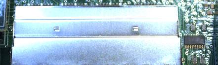
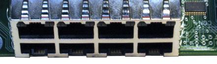
15 Mach Motion Wire all limit switches and solid state relays to the breakout board which is in the back of the CNC control. There are more diagrams on the following pages.

16 Mach Motion 16 To enable the limit switches in Mach3 go to Config / Ports&Pins / Input Signals. See Example below.
 Power for Board 5v DC While Charge pump is Enabled Charger Pump Signal Relays R2-R9 Can be Configured in Mach to be N.O.")
17 Mach Motion 17 Relay Out-put Configuration (Standard Configuration) Power for Board 5v DC While Charge pump is Enabled Charger Pump Signal Relays R2-R9 Can be Configured in Mach to be N.O. Spindle Control Relays 0-10v Spindle Control Index (Spindle Feedback) 5v 12v EN 17 CP CP R2 +R2 R3 +R3 R4 +R4 R5 +R5 R6 +R6 R7 +R7 R8 +R8 R9 +R9 CC CCW CW CW AO IDX Relay contacts are closed while charge pump is enabled 24VAC? Contactor Neutral Relay Coil

18 Mach Motion 18 Relay Input Configuration Power for Board 5v DC While Charge pump is Enabled Charger Pump Signal Relay +12v DC Spindle Control Relays 0-10v Spindle Control Index (Spindle 5v 12v EN 17 CP CP R2 +R2 R3 +R3 R4 +R4 R5 +R5 R6 +R6 R7 +R7 R8 +R8 R9 +R9 CC CCW CW CW AO IDX Relay contacts are closed while charge pump is enabled Limit Switch

 Function 1 Output 0-10V Spindle Ctrl 2 Output/Input R2 Relay 3 Output/Input R3 Relay 4 Output/Input R4 Relay 5 Output/Input R5 Relay 6 Output/Input")
19 Mach Motion 19 Parallel Port Pin-outs Pin 14 Pin 1 Parallel Port 1 Pin 13 Pin 26 Pin 14 Pin 1 Parallel Port Pin 26 Pin 13 Direction Parallel Port Pin # (relative to the PC) Function 1 Output Axis 6 Direction 2 Output Axis 1 Direction 3 Output Axis 1 Step 4 Output Axis 2 Direction 5 Output Axis 2 Step 6 Output Axis 3 Direction 7 Output Axis 3 Step 8 Output Axis 4 Direction 9 Output Axis 4 Step 10 Input Drive Error Input 11 Input 5-12v Input 12 Input 5-12v Input 13 Input 5-12v Input 14 Output Axis 5 Direction 15 Input 5-12v Input 16 Output Axis 5 Step 17 Output Axis 6 Step V DC Direction Parallel Port Pin # (relative to the PC) Function 1 Output 0-10V Spindle Ctrl 2 Output/Input R2 Relay 3 Output/Input R3 Relay 4 Output/Input R4 Relay 5 Output/Input R5 Relay 6 Output/Input R6 Relay 7 Output/Input R7 Relay 8 Output/Input R8 Relay 9 Output/Input R9 Relay 10 Input 5-12v Input 11 Input 5-12v Input 12 Input 5-12v Input 13 Input 5-12v Input 14 Output CW Spindle Relay 15 Input 5-12v Input 16 Output CCW Spindle Relay 17 Output Charge-Pump V DC

20 Mach Motion Connect drive power to servo drive and wire in Brake Resistor. Power Connector 240 VAC 3 PHASE U U V V W W P Break Resistor P Break Resistor C Break Resistor C Break Resistor D D L1 L2 L3 240 VAC POWER 240 VAC POWER L1 L2 L3 L1 POWER L2 POWER L3 POWER


21 Mach Motion Wire 24V from the 24V Power Supply to all drives Wire 115V Power into 24V Power Supply 115V Neutral
 and plug into CNC")


22 Mach Motion Route power cord (standard extension cord) and plug into CNC control. 11. Place cover back on CNC Control 12. Turn on CNC control and test motors. For more details on the I06 Breakout Board refer to the MachMotion I06 Motion Control Manual. For more details on Mach3 Control Software please refer to the Mach3 User Manual. You can find both of these manuals and other manuals in a folder on the desktop of your new CNC Control or you can download them off of MachMotion.com
23 Mach Motion 23 Notes:
24 14518 County Road 7240 Newburg, MO Website: MachMotion.com
MACHMOTION. Tool Setup. Using MachMotion s CNC Control 12/23/2010. Everything you need to know to setup your tooling in Mach3.
 MACHMOTION Tool Setup Using MachMotion s CNC Control 12/23/2010 Everything you need to know to setup your tooling in Mach3. Mach Motion Version 1.0.1 2 P a g e Copyright 2010, MachMotion.com All rights
Apollo I Breakout Board User s Manual
 MACHMOTION Apollo I Breakout Board User s Manual 1/14/2012 Everything you need to know to set up and use your Apollo I Breakout Board. MachMotion Version 1.0.1 2 P a g e M a c h M o t i o n Copyright 2012,
Stepper Drive Setup Guide
 MACHMOTION Stepper Drive Setup Guide 1/21/2011 Everything you need to know to connect your stepper motors to the MachMotion stepper drives. MachMotion Version 1.0.1 2 P a g e Copyright 2011, MachMotion.com
USB. USB Operator Panel Installation - Mach3
 USB USB Operator Panel Installation - Mach3 USB Operator Panel Installation - Mach3 1. Introduction 1.1 Overview System Components: X15-10-01 Operator Panel X15-20-01 MPG Pendant (Optional) 1.2 Tools Required
Ethernet. Ethernet Operator Panel Installation and Setup Pokeys Operating Panel Troubleshooting
 Ethernet Ethernet Operator Panel Installation and Setup Pokeys Operating Panel Troubleshooting Ethernet Operator Panel Installation and Setup Installation Guide Depending on the reasoning for the change
Apollo III INSTALLATION MANUAL
 Apollo III INSTALLATION MANUAL 2 P a g e 5/1/14 N0112 This manual covers the setup and configuration of the Apollo III motion controller connected to the control using Mach3. Formatting Overview: Menus,
Tool Setup USING MACH MOTION S CNC CONTROL. Specializing in CNC Automation and Motion Control
 Tool Setup USING MACH MOTION S CNC CONTROL Specializing in CNC Automation and Motion Control 2 P age 5/1/14 A0099 This manual covers the setup and configuration of tools using Mach3. Formatting Overview:
Stepper. Manuals about stepper drives. Stepper Drive Wiring Diagram - Apollo Stepper Drive Setup Guide
 Stepper Manuals about stepper drives Stepper Drive Wiring Diagram - Apollo Stepper Drive Setup Guide Stepper Drive Wiring Diagram - Apollo Cont rol Connect or Signal PUL+ PUL DIR+ DIR EN+ EN Color Brown/White
CNC 200MM COIL WINDER
 CNC 200MM COIL WINDER INSTRUCTIONS IMPORTANT: PLEASE READ THESE INSTRUCTIONS CAREFULLY TO ENSURE THE SAFE AND EFFECTIVE USE OF THIS MACHINE. Version 3 21/03/2018 [1] CONTENTS Declaration Of Conformity...
DIGITAL OBSERVATION GUARD LOW PROFILE PAN TILT KIT USER MANUAL
 DIGITAL OBSERVATION GUARD LOW PROFILE PAN TILT KIT USER MANUAL Version 2.1 June 4, 2013 0 Table of Contents Low Profile Pan Tilt Kit Description... 3 Low Profile Pan Tilt Unit Basic Operation... 4 Mounting
Breakoutboard für UC400ETH
 Breakoutboard für UC400ETH Operation Manual All rights to these operating instructions remain with cnc-technics. Texts, information and illustrations of these operating instructions may not be reproduced,
Manual. Model#-DB25M-3R6A. 6 Axis CNC Interface Breakout Board. Lastest update : Feb Store this manual away for further reference.
 Manual 6 Axis CNC Interface Breakout Board Model#-DB25M-3R6A Lastest update : Feb 2016 Read this manual carefully before making connections to the board. Store this manual away for further reference. Safety
Breakoutboard for ESS Smoothstepper
 Breakoutboard for ESS Smoothstepper Operation Manual All rights to these operating instructions remain with cnc-technics. Texts, information and illustrations of these operating instructions may not be
ASSEMBLY AND ADJUSTMENT
 EDGE-WALL MONITOR ARM EDGE-WALL Rev A 2/17 Model EDGE-WALL-SLV ASSEMBLY AND ADJUSTMENT EDGE-WALL MONITOR ARM PLEASE REVIEW these instructions before beginning the installation. Check that all parts and
Manual 5 Axis CNC Interface Breakout Board Model#-DB25-1R5AM
 Manual 5 Axis CNC Interface Breakout Board Read this manual carefully before making connections to the board. Store this manual away for further reference. Safety Notes: The electronics of the control
EASTERN LABS. Instructions Model RM /25/2007. Operation. Junction Box Assembly. Different Types of Switch Installations
 EASTERN LABS Instructions Model RM-1205 04/25/2007 Operation Junction Box Assembly Different Types of Switch Installations Counter Mounting Suggestions Operation Total Counter Mix Counter Thru counter
Ryobi 12 in. Sliding Compound Miter Saw With Laser Model No. TSS120L Repair Sheet
 Ryobi in. Sliding Compound Miter Saw With Laser Model No. TSS0L Repair Sheet 42 3 3 41 43 44 4 4 4 48 4 0 4 40 3 38 33 3 1 32 2 3 32 1 2 1 0 8 31 31 4 3 1 8 34 4 3 30 2 21 22 23 24 2 18 1 28 2 1 14 2 13
Nov. 07, 2013 p. 5 - changed the B axis unit value to from Changed by Randy per Frank s request.
 Correction notes Nov. 07, 2013 p. 5 - changed the B axis unit value to 45.1389 from 40.0000. Changed by Randy per Frank s request. Jan. 22, 2018 p. 5 - changed the B axis unit value and corresponding picture
AC300/AC400 SERIES DYNAMIC BRAKING and ADDITIONAL FORM C RELAY. INSTALLATION INSTRUCTIONS Document Number:
 Minarik Variable Speed AC Motor Drives AC300/AC400 SERIES DYNAMIC BRAKING and ADDITIONAL FORM C RELAY INSTALLATION INSTRUCTIONS Document Number: 250-0297 These instructions apply to models rated: 7.5 25
USER S MANUAL. C32- DUAL PORT MULTIFUNCTION CNC BOARD Rev. 4
 USER S MANUAL C32- DUAL PORT MULTIFUNCTION CNC BOARD Rev. 4 August, 2012 USER'S MANUAL TABLE OF CONTENTS Page # 1.0 FEATURES... 1-1 2.0 SPECIFICATIONS... 2-3 3.0 BOARD DESCRIPTION... 3-4 4.0 FUNCTIONAL
Plasma Retrofit Guide Upgrade Kit Installation Instructions
 Upgrade Kit Installation Instructions 1. TMC 3-in-1 Installation 1.1 Unplug the power cable from your CPR800 Control Unit and open the lid. Note The pictures show a NEMA 23 CRP800 Control Unit but the
IO3-R2 BREAKOUT BOARD
 IO3-R2 BREAKOUT BOARD DESCRIPTION Breakout board IO3-R2 (Revision R2) has digital buffer for STEP/DIR/ENA command signals and as such it is particularly suitable for the connection up to 4 microstep drives
CNC 200MM COIL WINDER
 CNC 200MM COIL WINDER INSTRUCTIONS IMPORTANT: PLEASE READ THESE INSTRUCTIONS CAREFULLY TO ENSURE THE SAFE AND EFFECTIVE USE OF THIS MACHINE. Version 2 15/08/2017 [1] CONTENTS Declaration Of Conformity...
USER S MANUAL. C33 - MULTIFUNCTION ROUTER BOARD BOARD Rev. 4
 USER S MANUAL C33 - MULTIFUNCTION ROUTER BOARD BOARD Rev. 4 June 2013 USER'S MANUAL TABLE OF CONTENTS Page # Contents 1.0 OVERVIEW... 3 2.0 FEATURES... 3 3.0 SPECIFICATIONS... 4 4.0 FUNCTIONAL BLOCK DIAGRAMS...
USER S MANUAL. C35S- QUICK SETUP BREAKOUT BOARD Rev. 1.3
 USER S MANUAL C35S- QUICK SETUP BREAKOUT BOARD Rev. 1.3 FEBRUARY, 2015 USER'S MANUAL TABLE OF CONTENTS Page # Contents 1.0 OVERVIEW... 1 2.0 FEATURES... 1 3.0 SPECIFICATIONS.... 2 4.0 BOARD DESCRIPTION...
USER S MANUAL. CNC Servo Stepper Motor Control Box CH4EV12-1 Rev. 1
 USER S MANUAL CNC Servo Stepper Motor Control Box CH4EV12-1 Rev. 1 January, 2013 i USER'S MANUAL TABLE OF CONTENTS Page # Contents 1.0 FEATURES... 1 2.0 SPECIFICATIONS... 2 3.0 SYSTEM REQUIREMENTS... 2
C33- MULTIFUNCTION ROUTER BOARD Rev. 2
 C33- MULTIFUNCTION ROUTER BOARD Rev. 2 User manual Rev. 1 1. Overview This card provides an easy way of interfacing your router based spindle with your steeper motor driver board. This board includes a
Part Name/Description Part Number Quantity
 Part Name/Description Part Number Quantity Direct Command Kit 4100883 1 Installation Instructions 2006336 1 Hardware Kit Large Module 2001354-1 2 Cable Installation Kit 2000901-1 1 Quick Reference Card
C-Series C142 Machine Controller Eurocard DIN Packaged Systems
 C-Series C142 Machine Controller Eurocard DIN Packaged Systems FEATURES: Available as 2- or 3-axes CNC Controller Remote START/STOP/RESET Bidirectional serial communication at up to 192 baud 32K of on-board
Part Name/Description Part Number Quantity
 Part Name/Description Part Number Quantity Direct Command 4200159 1 Cable Installation Kit 2000901-1 1 Hood 37-pin DSub 2001808-37 2 Dielectric Grease 2002872 1 Dust Plug 12 Pin Gray 2002899-12N 1 Feature
HDBB Breakout board user s manual
 HDBB Breakout board user s manual The HDBB breakout board was designed to use with our Whale2(-T)*, Whale3, Mammut* and Dugong servo drives or with any other third party stepper or servo drives which using
Installing 6 Indexer: PRS Standard Tools
 888-680-4466 ShopBotTools.com Installing 6 Indexer: PRS Standard Tools Copyright 2016 ShopBot Tools, Inc. page 1 Copyright 2016 ShopBot Tools, Inc. page 2 Table of Contents Overview...5 Installing the
4-axis parallel port encoder interface For Mach2/3 CNC control software. Closed loop operation for Servo and Stepper systems. General User s Guide
 Sound Logic Encoder Interface 4-axis parallel port encoder interface For Mach2/3 CNC control software Closed loop operation for Servo and Stepper systems General User s Guide Sound Logic James Cullins
UNIPORT V2. Uniport V2
 UNIPORT V2 Uniport V2 USB powered Parallel port interconnection board with optical isolated inputs, buffered outputs, charge pump interlock and power relays Specification Full optical isolation of all
AIR CUSHION TECHNOLOGY
 AIR CUSHION TECHNOLOGY Air Speed 5000 V3 PX3 PARTS CATALOG VER. 20110822 P1001 A5000 V1/V2/V3 BELT (TEFLON) P1021 A5000 V1/V2/V3 SMART V1/V2 KNIFE (SLITTER BLADE) P1112 A5000 V1/V2/V3 RUBBER NIP ROLLER
USER S MANUAL. C11S- MULTIFUNTCION CNC BOARD Rev. 1.2
 USER S MANUAL C11S- MULTIFUNTCION CNC BOARD Rev. 1.2 SEPTEMBER 2014 User s Manual Page i TABLE OF CONTENTS Page # 1. Overview... 1 2. Features... 1 3. Specifications... 3 4. BOARD DESCRIPTION... 4 5. Special
7" Touch Screen Display
 7" Touch Screen Display Installation Guide Contents Minimum Requirements...1 Select a Location...1 Initial Setup...2 Unboxing...2 Installation...3 Prepare the Panel...3 Install the Mounting Plate...3 Mount
uservo box instruction manual
 Safety notes uservo box instruction manual Every machine controlled by computer (PC) can be really dangerous for human life and health. Comply with bolow rules and use Your common sense while working with
Microscopic Imaging Research Station (MIRS) Assembly Guide. Version 1.0.0
 Assembly Guide. Version 1.0.0") Microscopic Imaging Research Station (MIRS) Assembly Guide www.adsyscontrols.com Adsys Controls, Inc.2012 Version 1.0.0 I. Assembly of the Adsys Controls MIRS system This document explains the assembly
Microscopic Imaging Research Station (MIRS) Assembly Guide www.adsyscontrols.com Adsys Controls, Inc.2012 Version 1.0.0 I. Assembly of the Adsys Controls MIRS system This document explains the assembly
VSDEPI VSD-E/XE Parallel Interface breakout board Manual Ver. 1.1
 Introduction VSD-E/XE Parallel interface is a breakout board designed to ease connection of up to four VSD-E/XE drives in single D-Sub 25 connector. Connector pin-out has been designed for step/dir operation
Installation Guide. Retrofit Kit for USB Ready Intraoral Systems
 Installation Guide Retrofit Kit for USB Ready Intraoral Systems Table of Contents Wall-Mount Retrofit Kit... 2 Introduction... 2 Connecting the Articulating and Horizontal Arm Cables... 2 Installing the
PP-BOB2-V2.0 PARALLEL PORT BREAKOUT BOARD
 PP-BOB2-V2 PARALLEL PORT BREAKOUT BOARD Document: Operation Manual Document #: T18 Document Rev: 1.0 Product: PP-BOB2-V2.0 Product Rev: 1.0 Created: October, 2015 THIS MANUAL CONTAINS INFORMATION FOR INSTALLING
Z-Truck (Vertical Moving) Z-truck Flag. Y-Truck (Horizontal Moving) FIGURE 1: VIEW OF THE Z-TRUCK. Flexshaft Assembly
 Z-truck Flag. Y-Truck (Horizontal Moving) FIGURE 1: VIEW OF THE Z-TRUCK. Flexshaft Assembly") Replacing the LCD Cable To remove and replace the LCD Cable you will need the following tools: #2 Phillips screwdriver (magnetic tip preferred) Socket wrench with 10mm socket Removing the Side Panel 1.
Replacing the LCD Cable To remove and replace the LCD Cable you will need the following tools: #2 Phillips screwdriver (magnetic tip preferred) Socket wrench with 10mm socket Removing the Side Panel 1.
APES-14 HD-6500 & HD-7000 Version Operator s Training Manual
 APES-14 HD-6500 & HD-7000 Version Operator s Training Manual Issue A1 09/03 PDI Part # 900600 Performance Design Inc. 2350 East Braniff St. Boise Idaho 83716 This manual contains very important safety
Cutter Option Installation Instructions
 This kit includes the parts and documentation necessary to install the cutter option on the Zebra XiII, XiIII, and XiIIIPlus-Series printers. NOTE: The Cutter Option is not available for the 96XiIII. Adding
Universal Tristop Cylinder for Cam Brakes
 Tristop for Cam Brakes 3rd Edition This publication is not subject to any update service. New versions are available in INFORM at www.wabco-auto.com Copyright WABCO 2006 Vehicle Control Systems An American
DigiSpeed-SD DC-06. Isolated Control Voltage Generator User s Guide. DigiSpeed-SD PCB Ver:3.0 Mach3 Ver: 2.+ DigiSpeed-SD - Users Guide Page 1
 DigiSpeed-SD - Users Guide Page 1 Updated: 4 th May 2011 DigiSpeed-SD DC-06 Isolated Control Voltage Generator User s Guide DigiSpeed-SD PCB Ver:3.0 Mach3 Ver: 2.+ DigiSpeed-SD - Users Guide Page 2 Homann
Rotator Genius Instruction Manual v1.3.3
 Rotator Genius Instruction Manual v1.3.3 OVERVIEW Device connection overview 4O3A Signature Rotator Genius is a smart, high integration rotator controller. It uses an electromagnetic sensor for reading
If you are missing any of the following items, please contact Stanton Video immediately (602)
") RIGHT ANGLE FOCUS Jan 03 If you are missing any of the following items, please contact Stanton Video immediately (602) 493-9505 1. Right Angle Focus Servo 2. Servo End Cap 3. Lens Gears (32 pitch, 48 pitch,.6
RIGHT ANGLE FOCUS Jan 03 If you are missing any of the following items, please contact Stanton Video immediately (602) 493-9505 1. Right Angle Focus Servo 2. Servo End Cap 3. Lens Gears (32 pitch, 48 pitch,.6
C11G- MULTIFUNTCION CNC BOARD Rev. 8.2
 C11G- MULTIFUNTCION CNC BOARD Rev. 8.2 User manual Rev. 2 1. Overview This card has been designed to provide a flexible interface and functions to your computer projects, by using the parallel port control
USER S MANUAL. M16 POKEYS MOTION MOTHERBOARD Rev. 1.1 JUNE 2016.
 USER S MANUAL M16 POKEYS MOTION MOTHERBOARD Rev. 1.1 JUNE 2016. USER'S MANUAL TABLE OF CONTENTS Page # Contents 1.0 OVERVIEW... 1 2.0 FEATURES... 1 3.0 BOARD DESCRIPTION... 2 4.0 SPECIFICATIONS... 2 4.1
Insert the male, 90 angled, 2x10 connectors into the corresponding 2x10 sockets and put them in place, flat under the PCB. Solder.
 MC624 Assembly guide Safety warning The kits are main powered and use potentially lethal voltages. Under no circumstance should someone undertake the realisation of a kit unless he has full knowledge about
PMDX-411 SmartBOB-USB with DB-25 Connector For use with Mach4
 PMDX-411 SmartBOB-USB with DB-25 Connector For use with Mach4 Quick Start Guide Document Revision: 0.4 Date: 6 May 2015 This document applies to units built on artwork revision PCB-522B. This is a rough
JIB EPT USER MANUAL. Please read this manual carefully before using the Alphatron JIB ETP unit! JIB & MOTORISED PAN AND TILT UNIT
 JIB EPT JIB & MOTORISED PAN AND TILT UNIT USER MANUAL EN Please read this manual carefully before using the Alphatron JIB ETP unit! Thank you for purchasing a Alphatron product The EPT head is developed
A-dec 570L Dental Light on a DCS System INSTALLATION GUIDE
 A-dec 570L Dental Light on a DCS System INSTALLATION GUIDE C ONTENTS Choose an Installation Guide...... Before You Begin.............. 3 Disconnect the Light Cable........ 3 Cut the Light Cable............
HD NO HOLES MOUNT RAM SSV
 HD NO HOLES MOUNT 2015-2019 RAM SSV 425-5107 Remove the two trim covers to access the front OEM bolts of the passenger seat. Remove the front bolts using a 15mm socket. Align the base to the holes, snug
CNC4PC. C11G - MULTIFUNCTION CNC BOARD Rev. 5.4
 CNC4PC Manual C11G - MULTIFUNCTION CNC BOARD Rev. 5.4 Overview This card has been designed to provide a flexible interface and functions to your computer projects, by using the parallel port control software.
MaxStepper Serial Step and Direction Pulse Generator. User Manual
 MaxStepper Serial Step and Direction Pulse Generator User Manual 2007 Kellyware 9/20/2007 WWW.KELLYWARE.COM Table of Contents Table of Contents... 2 Parts List... 3 Key Features... 3 Introduction... 4
VSDEPI VSD-E Parallel Interface breakout board Manual Ver. 0.9
 Introduction VSD-E Parallel interface is a breakout board designed to ease connection of up to four VSD-E drives in single D-Sub 25 connector. Connector pin-out has been designed for step/dir operation
DirectCommand Installation 5 Channel Spreader Control Module Technology
 DirectCommand Installation Ag Leader Technology Note: Indented items indicate parts included in an assembly listed above Part Name/Description Part Number Quantity Direct Command Kit 4100582 1 Cable Installation
USER S MANUAL VER.1. C11G- MULTIFUNTCION CNC BOARD Rev. 9
 USER S MANUAL VER.1 C11G- MULTIFUNTCION CNC BOARD Rev. 9 MARCH, 2017 User s Manual Page i USER'S MANUAL TABLE OF CONTENTS Contents Page # 1.0 OVERVIEW... 1 2.0 FEATURES... 1 3.0 SPECIFICATIONS... 2 4.0
Ag Leader Technology. DirectCommand Installation Hardi 20-pin Interface Kit (Sprayer Chassis Mount)
") Part Name / Description Part Number Quantity DirectCommand Hardi Sprayer Kit 4100882 1 Dust Receptacle 8-pin 2002975-8C 1 Installation Instructions 2006335 1 Quick Reference Card- Liquid Application 2002831-38
Part Name / Description Part Number Quantity DirectCommand Hardi Sprayer Kit 4100882 1 Dust Receptacle 8-pin 2002975-8C 1 Installation Instructions 2006335 1 Quick Reference Card- Liquid Application 2002831-38
QUICK-START GUIDE. Quick Start Guide Temperature Controlled QCM Cell WHAT DOES GAMRY SOFTWARE DO?
 www.gamry.com 1-215-682-9330 techsupport@gamry.com We have a variety of resources available to help you get started. Feel free to visit our website to find out more information on: Application Notes -
USER S MANUAL. C11- MULTIFUNTCION CNC BOARD Rev. 9.9
 USER S MANUAL C11- MULTIFUNTCION CNC BOARD Rev. 9.9 FEBRUARY, 2015 User s Manual Page i TABLE OF CONTENTS Page # 1. Overview... 1 2. Features... 1 3. Specifications... 3 4. BOARD DESCRIPTION... 4 5. Special
Plasma Control. Industrial Motion Control. Control Software Features. Optional Part Nesting. MachMotion.com
 Plasma Control Industrial Motion Control Large 17 touch screen for displaying part-shapepath Rugged control enclosure; dust/liquid resistant Closed-loop, DSP Ethernet motion controller Perfect for industrial
LED Lighting Kit For Elara NanoEdge Fixed Frame. Installation Guide. Attention: Read this guide before assembling your screen.
 LED Lighting Kit For Elara NanoEdge Fixed Frame Installation Guide Attention: Read this guide before assembling your screen. INTRODUCTION GETTING STARTED WARNING - Sharp Edges This product may contain
EVOLVE1-M MONITOR ARM
 EVOLVE1-M MONITOR ARM EVOLVE1-M Rev A 2/17 Model EVOLVE1-M-SLV Model EVOLVE1-M-BLK Model EVOLVE1-M-WHT ASSEMBLY AND ADJUSTMENT EVOLVE1-M MONITOR ARM PARTS AND TOOLS PLEASE REVIEW these instructions before
1000 Series Lathe Control OPERATING MANUAL. Specializing in CNC Automation and Motion Control
 1000 Series Lathe Control OPERATING MANUAL Specializing in CNC Automation and Motion Control 2 P age 6/24/15 G0131 This manual covers the operation of the 1000 Series Lathe Control. Formatting Overview:
X USER MANUAL. Specializing in CNC Automation and Motion Control
 X15-200 USER MANUAL Specializing in CNC Automation and Motion Control 2 P a g e 5/1/14 R0103 This manual covers the setup and configuration of the kitten motion controller connected to the control using
Floor Standing Pedestal
 2336 K052 Floor Standing Pedestal Kit Instructions Issue C Revision Record Issue Date Remarks A Feb 20021 First issue B June 2007 Added pedestal floor bolting procedure C Mar 2011 Added Universal Mounting
CAMERA ASSEMBLY. Removal/Replacement of the Camera Box Assembly APR-CA. Install Camera Assembly. Remove Camera Assembly
 CAMERA ASSEMBLY Removal/Replacement of the Camera Box Assembly APR-CA REQUIRED TOOLS: 9/64 hex key Small flat-tip screwdriver Remove Camera Assembly camera 1. Locate the camera assembly underneath the
Rako RAK4-R Instruction Manual
 Rako RAK4-R Instruction Manual Before Attempting To Program A System Refer To One Of The Following Documents : RAK4 Wireless System Setup Guide (Systems Controlled By An RxLink) Wired System Programming
MK-101 TILE SAW OWNER S MANUAL & OPERATING INSTRUCTIONS SERIAL NUMBER:
 MK-0 TILE SAW OWNER S MANUAL & OPERATING INSTRUCTIONS CAUTION: Read all safety and operating instructions before using this equipment Enter the Serial Number of your new saw in the space below. The Serial
SPECIAL INSTRUCTIONS FOR CAPACITORS COMPACT GENERATORS
 SPECIAL INSTRUCTIONS FOR CAPACITORS COMPACT GENERATORS (WITH CAPACITOR CHARGER BOARD A3517-02) The process depends on Generator and System configuration. This document applies to installation of Capacitors
GDPS. Power supply unit for XtrapulsGem drive
 GDPS Power supply unit for XtrapulsGem drive WARNING This is a general manual describing a power supply unit for the supply of INFRANOR XtrapulsGem drives having output capability suitable for driving
BPL SERIES INSTALLATION INSTRUCTIONS THIS SHEET CONTAINS IMPORTANT SAFETY INSTRUCTIONS. SAVE THESE INSTRUCTIONS.
 BPL SERIES INSTALLATION INSTRUCTIONS Important Warning THIS SHEET CONTAINS IMPORTANT SAFETY INSTRUCTIONS. SAVE THESE INSTRUCTIONS. This product must be installed in accordance with National Electrical
TMC3in1 Torch & Motion Controller 3in1. Vol. 04: FAQ and Troubleshooting Guide
 TMC3in1 Torch & Motion Controller 3in1 Plasma THC - 5 Axis Breakout Board Spindle Controller Vol. 04: FAQ and Troubleshooting Guide For use with TMC3in1 Plugin Rev: 4.2.x.x Author: Randall L Ray Very Sr.
USER S MANUAL. CNC Stepper Motor Control Box CS3EA4-1 Rev. 1
 USER S MANUAL CNC Stepper Motor Control Box CS3EA4-1 Rev. 1 April, 2012 USER'S MANUAL TABLE OF CONTENTS Page # Contents 1.0 FEATURES... 2 2.0 SPECIFICATIONS... 3 3.0 SYSTEM REQUIREMENTS... 3 4.0 WARNING...
UCBB dual port breakout board user's manual
 UCBB dual port breakout board user's manual 1/14 Contents 1 Features 2 Dimensions 3 Connectors 3.1 Screw terminals 3.2 IDC ports 3.3 Powering 3.4 Outputs 3.5 Inputs 4 LED indicators 5 Example connections
Assembly Manual for Mobile X-ray
 Suitable for Kodak 2000, Kodak 2100, Kodak 2200 and Trophy Elytis - 12 th January 2011 William Green Page 1 of 8 Printed 12/01/2011, 2:07:42 PM Mobile X-ray Parts List 1. 6 x M10 x 65mm UNB CAP Bolts 2.
USBCNC USB Disk Key reader for CNC Controls Machine Mount instructions
 USBCNC USB Disk Key reader for CNC Controls Machine Mount instructions 2008-2015 Calmotion LLC, All rights reserved Calmotion LLC 21720 Marilla St. Chatsworth, CA 91311 www.calmotion.com Introduction This
CODE 50108, 50110, 50164, 50165
 CODE 50108, 50110, 50164, 50165 ASSEMBLY PAGE NAME Machine Assembly Machine Assembly Machine Assembly (Wire feed chamber) Machine Assembly (Wire feed chamber) Feeding Unit Assembly CODE NO.: K NO.: FIGURE
Apollo III User Manual - Mach3
 Apollo III User Manual - Mach3 WARNING! Improper installation of this motion controller can cause DEATH, INJURY or serious PROPERTY DAMAGE. Do not attempt to install this controller until thoroughly reading
PP-BOB2-V1.0 PARALLEL PORT BREAKOUT BOARD
 PP-BOB2-v1 PARALLEL PORT BREAKOUT BOARD Document: Operation Manual Document #: T17 Document Rev: 2.0 Product: PP-BOB2-v1.0 Product Rev: 1.0 Created: March, 2013 Updated: Dec, 2014 THIS MANUAL CONTAINS
Instruction Manual. Gold Pan Tilt Head with 12V Joystick Control Box (PT-GOLD)
") Instruction Manual Gold Pan Tilt Head with 12V Joystick Control Box (PT-GOLD) All rights reserved No part of this document may be reproduced, stored in a retrieval system, or transmitted by any form or
Instruction Manual Gold Pan Tilt Head with 12V Joystick Control Box (PT-GOLD) All rights reserved No part of this document may be reproduced, stored in a retrieval system, or transmitted by any form or
Tile Plow Installation O Connell
 NOTE: Indented items indicate parts included in an assembly listed above Part Name/Description Part Number Quantity Tile Plow Kit O Connell System 4100471 1 Hex head cap screw 3/8-16 x 3 2002003-38300
UNIPORT V3. C R H Electronics Design
 UNIPORT V3 V C R H Electronics Design Uniport V3 USB powered Parallel port interconnection board with optical isolated inputs, buffered outputs, charge pump interlock and power relays By C R Harding Specification
Hardware Installation. In this chapter... Custom Labels EMI Noise Filter Installation Mounting DIN Clip Mounting Connections and Wiring
 Hardware Installation 2 In this chapter... Custom Labels EMI Noise Filter Installation Mounting DIN Clip Mounting Connections and Wiring Custom Labels Create Custom Labels You may create custom labels
Control Box Setup - PRSalpha
 888-680-4466 ShopBotTools.com Control Box Setup - PRSalpha Copyright 2016 ShopBot Tools, Inc. page 1 Copyright 2016 ShopBot Tools, Inc. page 2 Parts List: Hooking Up a PRSalpha Gantry Tool Powering the
Motorized Capacitor. Electrical Installation of ID-400. Service Bulletin 63
 Plasma Control Technologies Service Bulletin 63 Motorized Capacitor Electrical Installation of ID-400 Document Information Authors... O. Lehmann / A. Renggli / T. Fenske... W. Bigler / M. Armbruster Document...
MO-SYS L 40-3rd Axis Quick Set-up Guide
 MO-SYS L 40-3rd Axis Quick Set-up Guide WILLIAM F. WHITE INTERNATIONAL INC. Manual Version 1.0 Questions or concerns, please contact Michael Darby 416.707.1549, mdarby@gmail.com MO-SYS L 40 3rd Axis Intro
Rider AMP TM. Parts Manual. Model In. S.D. Deck /09 Printed in USA
 AMP TM Parts Manual Rider Model 900 -In. S.D. Deck 0800 /09 Printed in USA THE MANUAL Before you operate your unit, carefully and completely read manuals supplied with the unit. The contents will provide
Owner s Manual SGA 100 And SGA 100C NOTE NOTE. 1. Safety Symbol Definitions. 2. Weld Control Specifications. 3. Duty Cycle
 Owner s Manual SGA 100 And SGA 100C October 2001 FORM: OM-190 753H Use above FORM number when ordering extra manuals. 1. Safety Symbol Definitions Warning! Watch Out! There are possible hazards as shown
RTK4 Logic Controller User Manual For RTK4L Revision Revised
 RTK4 Logic Controller User Manual For RTK4L Revision 120326 Revised 6-20-12 RTK4 Features Application: PLC and Third Party Drive Interface Number of Axis Drive Interfaces: 5 Axis DAC Resolution: 16 bits
Q2 XBee Handheld Controller Assembly Guide
 Q2 XBee Handheld Controller Assembly Guide Copyright Quantum Robotics Inc. Q2 Controller V1.0 1 Parts List: The kit comes with 14 individual bags. 1. Case Top and Bottom 2. Case Screw Package containing:
A Axis M-Functions Level 1 A Axis Standard A Axis SMT Level 2. Each console includes the following:
 Hardware List The 3000M Crusader II Upgrade system has been custom configured to provide the necessary hardware required for installation on your machine. Verify that you have received all the correct
C35- QUICK SETUP BREAKOUT BOARD Rev. 1.1
 C35- QUICK SETUP BREAKOUT BOARD Rev. 1.1 User manual Rev. 1 1. Overview This card provides an easy way of interfacing your inputs and outputs from the parallel port. It provides terminals and RJ45 for
Preparing for a Docking Drawer Slim Installation To prepare for a successful Docking Drawer Slim installation please ensure that the cable management
 Docking Drawer Install Manual Docking Drawer Slim Series Applicable Models: 0290 00031(W) / 24 0290-00030(W) / 21 0290-00047(W) / 18 0230-00004. r6 1/19/2016 CAUTION READ CAREFULLY Failure to follow these
Parts Manual Kleen Sweep 32R Rider Sweeper
 Parts Manual Kleen Sweep 32R Page 2 Table of Contents Side broom R.H., part 1... Side broom R.H., part 2... Front wheel drive... Accelerator... Steering... Seat group... Group of main sweeper roller, part
Ndrive Linear Series. Digital Servo Amplifiers Linear. Output power range of 10 or 20 A peak with ±10 to ±80 VDC bus
 Ndrive Linear Amplifiers/Drives Ndrive Linear Series Digital Servo Amplifiers Linear Output power range of 10 or 20 A peak with ±10 to ±80 VDC bus 2- or 3-phase AC line input or DC input CE approved and