FTI 3000 Manual Lookout Road, Boulder, CO Phone: Fax:
|
|
|
- Cody Snow
- 5 years ago
- Views:
Transcription


1 FTI 3000 Manual 6655 Lookout Road, Boulder, CO Phone: Fax:
2 Specifications... 3 Configuration Parameters and Test Conditions... 4 Diode String Configuration and Naming Conventions... 5 Cabling Option 1 & Cabling Option Cabling Option Translation Board... 9 Lambda Power Supply Configuration Launching Burner Application Configuration Tab Operation Tab Phase Meter Light Pole Status Adding run-time comments System Health Diode String Status Diode Location Translator Failure Symbols Plotting Tab Channels Tab Excel and Minitab backup file naming convention Quick Keys Launching BIAG (diagnostics) Application Connection Tab Diagnostic Tab Calibration Tab... 46
3 Specifications Tj ( C) Vf (V) Result is based on the Vf measurement and the Kfactor and Vf@25 C entry parameter accuracies (*3). +/- 0.5% of measured value. Vz (V) +/- 0.8% of measured value (*2). IHeat (A) +/-10% of measured value (*1, *2, *4). *1) Measurement is not calibrated. *2) Measurement is not used for temperature regulation. *3) Tj C = 25 + ((Vf@25 C Vf measurement) / Kfactor). *4) IHeat current is adjusted up or down to change the Diode Vf in order to maintain prescribed temperature. Meter Accuracy 100mV Range 1V Range 10V Range 40V Range 400V Range 800V Range 0.15% of Value +/- 1mV 0.15% of Value +/- 1mV 0.15% of Value +/- 4mV 0.15% of Value +/- 10mV 0.3% of Value +/- 100mV 0.3% of Value +/- 200mV Maximum operating condition Maximum 600V. 2.5A per IHeat current source.
4 CONFIGURATION PARAMETERS AND TEST CONDITIONS: This section refers to a Configuration tab which will be described later in this manual. Regulation and Filler diodes will also be defined later in this manual. The following conditions cause a diode failure status: Exceed Vz minimum or maximum limit. - Limit is based on Vz Tolerance Configuration tab entry parameter. - Measurement is Vz. Exceed maximum total wattage of all active strings. - Limit is based on Max Watts Configuration tab entry parameter. - Measurement is the sum of heating current * Vz of all active diode strings. Exceed Tj minimum or maximum limit. - Limit is based on Temperature Tolerance Configuration tab entry parameter. - Tj is computed using measured Vf and Vf@25 C and Kfactor Configuration tab entry parameters. A failure will turn on the Yellow light and continue burn-in testing. It is possible for a diode to return to normal passing condition. For example, air movement change across the diode and either the air movement ceases or the heating current eventually adjusts accordingly. The following conditions will cause a diode string to be removed from test: Voltage on high-side (Vtop) of Regulation diode is too high. - Limit is based on Vz, Vz tolerance and String Length Configuration tab entry parameters (plus additional tester operating voltage margin). - Measurement is high-side (Vtop) of Regulation diode voltage. - Possible reasons: Power supply voltage is too high or Filler diode(s) are shorted. Voltage on high-side (Vtop) of Regulation diode is too low. - Limit is based on Vz, Vz tolerance and String Length Configuration tab entry parameters. - Measurement is high-side (Vtop) of Regulation diode voltage. - Possible reasons: Power supply voltage is too low or Filler diode is open.
5 Heating Current is too high. - Current Range selection is based on Vz, Vz tolerance and Max Wattage Configuration tab entry parameters. - Measurement is Regulation diode heating Current Source. - Possible reasons: Incorrect entry parameter or too much air flow across Regulation diode. Vf is below 0.2V or above 0.9V. - Measurement is Vf. - Possible reasons: Regulation diode failure. Tester module temperature exceeds 70 C. - Measurement is from a Thermister on each Current Control Module inside the Tester.
6 FTI 3000 Configuration + Diode Supply Filler diodes when 10 length selected 10 length 5 length X5 Filler diodes Regulation diode Vtop Vbottom X5 F F S S S F F S To Tester Strings 1-5 (5 or 10 length) Strings 6 10 (5 length only) 40 pin connectors
7 Cabling Option 1 & 4 Option 1 two full frames or Option 4 of two full frames with alternating diodes and blanks populated on Diode Boards Frame 1 Frame 2 C1 C2 C3 C4 C5 C1 C2 C3 C4 C5 C1 C2 C3 C4 C5 C1 C2 C3 C4 C5 Translator M1 M2 M1 M2 M1 M2 M1 M2 J1 J2 J3 J4 J1 J2 J3 J4 Tester
8 Cabling Option 2 Full Frame Option 2 one Full Frame, Configured as 5 Length Empty Frame Frame 1 Frame 2 C1 C2 C3 C4 C5 C1 C2 C3 C4 C5 C1 C2 C3 C4 C5 C1 C2 C3 C4 C5 Translator M1M2 M3 M4 M1M2 M3 M4 M1M2 M3 M4 M1M2 M3 M4 J1 J2 J3 J4 J1 J2 J3 J4 Tester
9 Cabling Option 3 ½ frame A Option 3 two ½ frames, Configured as 5 Length ½ frame B Frame 1 Frame 2 40 pin C1 C2 C3 C4 C5 C1 C2 C3 C4 C5 Translator C1 C2 C3 C4 C5 C1C2 C3 C4 C5 M1M2 M3 M4 M1M2 M3 M4 50 pin J1J2 J3 J4 J1 J2 J3 J4 Tester - + Power Supply Tester
10 Translator Each config board, 5 channels (1-5) for 10 Length configuration (routes to M1 and/or M2 of Translator board) or 10 channels (1-10) for 5 Length configuration (routes to M1, M2, M3 and/or M4 of Translator board). 40 pin C1 C2 C3 C4 C5 M1 M2 M3 M4 (50 pin) M1 & M2 of Translator board always used for 10 Length and 5 Length configurations M3 & M4 of Translator board used only for 5 Length configuration 12 ½ channels 12 ½ channels 25 channels
11 Lambda Power Supply Configuration To translator boards Computer + - >= 700V 60A (IR 70HFLR60S02) 200V Address = 1 Dip Switches Up: 6 Dip Switches Down:1-5, 7-9 RS V >= 700V 60A (IR 70HFLR60S02) Address = 2 Dip Switches Up: 6 Dip Switches Down:1-5, 7-9 RS485 >= 600V 100A V Slave Address = 3 Dip Switches Up: 2 & 6 Dip Switches Down:1, 3-5, 7-9 RS485 >= 600V 100A V Master Address = 0 Dip Switches Up: None Dip Switches Down: All RS232 To Testers Baud Rate of all Power Supplies must be set to 2400.
12 The Burner software component of the FTI3000 system is the module that the operator uses to run and perform the various tests against the diodes To run the Burner software, double click After launching the burner software, the following screen will appear The screen will look slightly different depending on whether a 5 length was selected or a 10 length was selected. The screen capture above shows the Configuration tab with a 5 length selected. The screen is divided into four tabs: Configuration, Operation, Plotting and Channels
13 Various parameters on the Configuration tab will be set based upon what is chosen from the device file field. The Load button must be pressed in order update the configuration information from the device file. The device file field controls the following values on the Configuration tab: Cabling Option Selection String Size Max Dead Strings Zener Voltage Zener Voltage Tolerance 25 C K Factor Alpha (modifies operational Vz = ((Tj 25) * Alpha / 100.0) + Zener Voltage) Temperature Max Temperature Tolerance Max Power Burn In Time Data logging sample rate Almost all of the fields are populated based on the Device File field on the Configuration tab except for Operator ID and Lot Number. In addition the

14 Cabling Option Selection field controls translator dialog boxes. This will be discussed later in the manual. In addition there is a Comments/Notes section in the Configuration tab to allow you to enter comments before the test is begun. These comments become part of the log files that are created when the test is completed. If the Mod indicator is visible, it indicates that one or more parameters have been modified and not saved.

15 These settings can be saved by going to the File Save menu (Engineering mode only).


16 The Operation tab is where the testing is started. The above screen shows the Operation tab during the middle of a test. When the tab is initially clicked, in order to run the test, the operator must click the Run button in the Power section of the tab. Notice in the image below the Diode Power indicator is off, since the test has not begun.

17 To begin the running of the test, click icon on the operation tab. Note: The phases can also be run through by manually sliding the slider on the phase meter (Engineering or Maintenance modes only). Usually this is done for diagnostic purposes. Once the Run icon has been clicked, the Phase indicator will change from 0 to indicate that the test is currently running. CAUTION NOTICE: When the Diode Power Supplies are on, the Diode Power indicator will be bright Red. This means that there is high voltage present and extreme caution should be exercised to prevent electrical shock hazard. Even if the indicator is not red, extreme caution should still be maintained as the software can get disconnected from the actual Power Supply state. Always check the meter indicator on the Power Supplies for voltage status.
18 The Phase Meter shows you what phase the test is currently in. There are three phases of the test: Phase 1 - Diode check (checks regulation diode). Phase 2 - Ramp up - ramps up power supplies in voltage increments then ramps up Diode temperature to operating condition (preheat). Phase 3 - Data starts getting recorded (regulation mode). NOTE: Any diode failure in Phase 2 will terminate the test regardless of the Max Dead Strings configuration tab parameter. This is so that the failure can be remedied before going into regulation mode, Phase 3.
19 The test can have different statuses to alert you as to how the test is proceeding. The status lights correspond with the light pole on top of the system. : The statuses are as follows: Light Color Meaning White Blue Green Yellow Red Flashing Green and White System idle. Diode check or Ramp-up in progress. Test is running successfully. Requires attention. Regulation mode is still running. Warning, requires immediate attention. Regulation mode abnormally terminated. Test is complete. The meaning of each status can also be obtained by clicking on the status light in the window.

20 When one of the status lights is clicked, a dialog box will pop up indicating the meaning of that light White: Blue: Green:


21 Yellow: Red: Once the test has reached Phase 3 data then will be logged for the test. The logged data is stored in two locations, in flash memory on the board and also as a text file in C:\DiodeBurnIn\Folder# where the folder number corresponds to the lot number listed on the configuration tab. Additionally the progress meter will indicate how much progress has been reached during Phase 3.

22 During the testing, there are three other windows that can give you information regarding the testing of a specific diode. 3 1 a b 2 Window 1: Provides text messages with information about the diode being tested. Additionally comments can be entered at the bottom of the window, by typing the comment in and then clicking the Insert Comment button (as shown by steps (a) and (b). These comments get stored in the log file that is generated through-out the test. Window 2: Each diode, represented as a block, lights with a color indicating if the test on that diode was successful, encountered a problem, etc. Additionally, clicking on the block brings up a graphical form that translates the location of diodes for that specific diode string. This is talked about later in the manual. Window 3: Graphical representation of the parameter the diode is operating at.


23 Another informational area on the operations tab is the System Health section. This section advises as to the percentage of diode strings that are in tolerance and the number of dead strings for each of the three phases. There is a drop down box that allows you to choose exactly which test on the diode is to be viewed. All tests are continually performed on the diode.

24 The String Status area of the Operation Tab allows you to click in the String Click Selection radio buttons in order to choose which graphical representation of the diode(s) location. The Cabling Option Selection field on the Configuration tab controls what the Translator dialog boxes display. Right-clicking on the box will select that corresponding diode string for waveform viewing.

25 Below is a diagram of the Translator graphical form with all the components marked. Clicking on the String selection box can be used to translate the location of the corresponding diode string.

26 Choosing All diodes in string results in
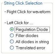

27 Selecting Regulation Diode results in

28 Selecting Filler diodes results in

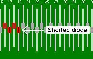

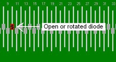
29 Translator Diode failure symbol definitions and meanings:

30


31 Right-clicking on a box in the String Status grid displays the results in the test window and indicates which string measurement is displayed. Clicking on the String Number text will toggle the active string number selection item. Note the Asterisk preceding the number. This shows which wave form is the active item.

32 The Plotting tab shows the waveform for the various tests that have run against the diodes The Bar Chart shows a particular measurement result for all active diode strings under test. The Green bar shows the current state of the diode string, and the Gray bar shows the minimum and maximum history range. The history length is the same length as the Waveform Graphs. To change the Bar Chart measurement result type, click on any of the waveform graphs. The Waveform Graphs show only a particularly selected diode string. To change the diode string selection, click any where on a bar in the Bar Chart, or go to the Operation tab and select the diode string from the String Status grid. The String Number in the Legend shows which diode string is actively shown in the Waveform Graphs. Click over the desired String Number Legend to make that String Number the active item when selecting the desired String Number. Note the Asterisk (*) preceeding the String Number text. This shows which Waveform is the active item.

33 The Channels tab (Engineering and Maintenance modes only) allows you to select which diodes are to be tested. The best way to select which strings are being tested is to click the button. The auto button pre-selects which strings are tested by checking to see whether a diode has been inserted correctly into that specific position. Clicking the button selects all the strings and clicking the button clears all the selections. By using the Auto button, you can also check to see whether the diodes have been inserted correctly, since if they are not, the box will not be selected.
34 Excel and Minitab backup file naming convention Whenever a new run is performed and there is an existing Excel and Minitab file in the Lot directory, the previous run files will get renamed in the following convention: Excel_lotID_YYYYMMDD_hhmmss.bak Minitab_lotID_ YYYYMMDD_hhmmss.bak Where: YYYY = Year. MM = Month. DD = Day. Hh = Hour. Mm = Minute. Ss = Second. For example, Excel_lotID_ _ bak was backed up on Feb 22, 2010 at 3:32:28 pm.
35 QUICK KEYS Any tab: KEY PG-UP PG-DN ACTION Previous tab Next tab Configuration tab: KEY TAB SHIFT + TAB CTRL + S CTRL + O ACTION Next parameter. Previous parameter. Save (Engineering mode only). Load settings from file. Operation tab: KEY F5 F7 CTRL + M CTRL + N SPACE Numeric numbers 0-9 ACTION RUN Stop Enable comment entry. Enable String Number entry. Toggle String Number selection. Change String Number value. Plotting tab: KEY F5 F7 UP-Arrow DN-Arrow SPACE Numeric numbers 0-9 CTRL + SHFT + K ACTION RUN Stop Bar Chart select previous plotting data set. Bar Chart select next plotting data set. Toggle String Number selection Legend item. Change String Number value. Clear Plots.
36 Software Component - BIAG The BIAG (Burn-in Diagnostic) software component of the FTI3000 system is used by the application engineers and maintenance to maintain and test the system. To launch BIAG, select Biag from the Windows menu system: START - Program Files - FTI - Biag The following screen will appear

37 Software Component - BIAG BIAG is made up of three tabs: Connection, Diagnostics and Calibration

38 Software Component - BIAG The Connection tab allows you to turn the power on and off to the board by clicking the drop down menu. icon. Additionally you can select the board from the Reset/Recovery used for USB disconnects COM Port# used for Calibration and Verification To change board selections, first press the Green Connect button so that it turns Red. Select the desired board ID from the drop-down list and then press the Red Connect button. After the board is connected, the button will turn Green. Reset/Recovery button is used for USB disconnects. If that is the case once the Reset/Recovery button is clicked, the power must be turned on and off. The DMM used for Calibration and Verification is selected with the DMM Port Selection COM Port #. Port 0 disables the DMM. The typical COM Port number is 1, but other COM Ports are possible, depending on the computer and hardware setup.
39 Software Component - BIAG The Diagnostic tab is where you get to pick the specific diagnostic that is to be run. 2 1 Window 1 is where the specifics regarding the diagnostic are chosen. Window 2 is the output or results of the diagnostic that is/was being performed.

40 Software Component - BIAG The Diagnostics section of the Diagnostic tab is where the specific diagnostic to be run is chosen. You can choose the following diagnostic tests: Flash state, RAM test, Flash Test, Light Pole Interface Test, Measurement check and Relay. All of these tests can be run at once. Flash state indicates the state of the flash memory on the board. RAM Test checks the amount of memory. Flash Test allows you to test the flash memory on the board. Light Pole Interface Test allows you to test the board-to-board light pole interface circuitry. You must use the Lights section to test the light pole driver circuitry and light pole lights. You can control how many times the test is run through by clicking the Loops drop down. In order to begin the test(s) click
41 Software Component - BIAG The results of the test(s) will appear in Window 2. 2 If logging has been enabled, the results shown in Window 2 will be placed in a log file under C:\DiodeBurnIn\Log. At any point in time, if you wish to clear the results from the Window 2, you can right click and clear the results. Right clicking in the Diagnostics section also allows you to open the results screen in a more detailed window.

42 Software Component - BIAG If a diagnostic has passed a test, the following screen will be shown. Indicators appear both on the menu bar and in Window 2 to let you know the diagnostic passed.
43 Software Component - BIAG Correspondingly, if a diagnostic has failed the following window will appear. Again, indicators on the menu bar and in Window 2 will let you know the diagnostic failed. The Clear All button, made., deselects all the diagnostic choices that were

44 Software Component - BIAG The Clear Flash Data button allows the operator to clear the existing data out of the flash memory. The Erase Flash Memory button completely clears and wipes out the contents of the flash memory on the board. Clear Flash Data button Erase Flash Memory button
 Tests power supply Checks the regulation diode The Check button")
45 Software Component - BIAG Diode Polarity checks the polarity of the diode. The results correspond to the colors on the light pole. Red indicates a short Green indicates the polarity is fine Yellow indicates that it is open Checks polarity of the diode(s) Tests power supply Checks the regulation diode The Check button (Engineering mode only) checks the same parameters as the Operator(Burner) GUI but only checks the regulation diode. Check, Ramp & Regulate (Engineering mode only) tests power if the power is able to be manually adjusted from the power supply. Reg 1X (Engineering mode only) runs the regulation algorithm 1 time on all channels whether the channel contains a diode string or not. This can be used for debug or diagnostic purposes in which the normal Check, Ramp & Regulate method continually fails. Lights area allows you to click on a specific color to test that color light on the light pole. The Refresh button test to see what light is currently on, on the light pole and highlights that color in the box.

46 Software Component - BIAG The Calibration tab is used when an operator utilizes a calibration tool.
WVL2 Wireless Vehicle Link 2 Installation and Setup Manual
 WVL2 Wireless Vehicle Link 2 Installation and Setup Manual Chapter 1: Introducing the Wireless Vehicle Link 2...1 WVL2 Components...2 Component Checklist...3 Product Specifications...4 System Requirements...5
Fluke Metrology Software
 Fluke Metrology Software Version 7 MET/CAL 5500/CAL Getting Started Guide P/N 1275404 July 1999 Rev. 2, 9/04 1996-2004Fluke Corporation, All rights reserved. Printed in U.S.A. All product names are trademarks
NORDSON CORPORATION AMHERST, OHIO USA
 CanWorks Operator Interface Tracking PLUS for CanWorks Systems with SM-2 Spray Monitors User Guide Part 1018132A NORDSON CORPORATION AMHERST, OHIO USA 2002 Nordson Corporation. All rights reserved. CanWorks,
Mac Version. User Guide. September Toll-Free: Page 1 of 24
 Mac Version User Guide September 2007 Toll-Free: 866-746-3015 Page 1 of 24 www.turningtechnologies.com Checking the Version of TurningPoint for Mac Installed If you already have TurningPoint installed
DATA ARCHIVING SOFTWARE V.
 Interscan Corporation. ARC-MAX III - DATA ARCHIVING SOFTWARE V. 2.1.0.9 OPERATION MANUAL 1 Contents 1 Opening the program.... 3 2 Login Window... 3 2 Menu & Toolbar... 4 2.1 Current Data Display... 5 2.2
VANGUARD LOAD TAP CHANGER ANALYZER (LTCA) VERSION 2.xx SOFTWARE MANUAL. LTCA-10, LTCA-40, WRM-10P, WRM-40, TRM-20, TRM-40, TRM-203, and TRM-403
 VERSION 2.xx SOFTWARE MANUAL. LTCA-10, LTCA-40, WRM-10P, WRM-40, TRM-20, TRM-40, TRM-203, and TRM-403") VANGUARD LOAD TAP CHANGER ANALYZER (LTCA) VERSION 2.xx SOFTWARE MANUAL For Use with Vanguard s LTCA-10, LTCA-40, WRM-10P, WRM-40, TRM-20, TRM-40, TRM-203, and TRM-403 Load Tap Changer Analyzers and Winding
VANGUARD LOAD TAP CHANGER ANALYZER (LTCA) VERSION 2.xx SOFTWARE MANUAL For Use with Vanguard s LTCA-10, LTCA-40, WRM-10P, WRM-40, TRM-20, TRM-40, TRM-203, and TRM-403 Load Tap Changer Analyzers and Winding
User Manual Australia
 User Manual Australia April 2009 EAZ0057B06A Rev. A Trademarks Acknowledgements Snap-on, ShopStream Connect, ETHOS, MODIS, SOLUS, SOLUS PRO, and Vantage PRO are trademarks of Snap-on Incorporated. All
Thermal Transient Test Installation and Operating Manual
 Thermal Transient Test Installation and Operating Manual 2705A De La Vina Street Santa Barbara, California 93105 Telephone (805) 682-0900 descon@silcom.com www. santabarbaraautomation.com Installation
Lesson 4 Implementing a VI
 Lesson 4 Implementing a VI A. Front Panel Design B. LabVIEW Data Types C. Documenting Code D. While Loops E. For Loops F. Timing a VI G. Iterative Data Transfer H. Plotting Data I. Case Structures A. Front
EU Driver s Hours Rules covered by Digifobpro. Table of contents
 EU Driver s Hours Rules covered by Digifobpro Digifobpro provides analysis of Driver Cards both in it s Quick View and Driver Card - Download features ( see Digifobpro Functions page 4). There follows
IT Essentials v6.0 Windows 10 Software Labs
 IT Essentials v6.0 Windows 10 Software Labs 5.2.1.7 Install Windows 10... 1 5.2.1.10 Check for Updates in Windows 10... 10 5.2.4.7 Create a Partition in Windows 10... 16 6.1.1.5 Task Manager in Windows
INSTRUCTION MANUAL MODEL 8081 DIGITAL RECORDER
 INSTRUCTION MANUAL MODEL 8081 DIGITAL RECORDER Revision B February 2013 P/N 8081-0005 S/N 2001 N. Indianwood Ave., Broken Arrow, Oklahoma 74012 Tel: 918-250-7200 Telefax: 918-459-0165 E-mail: Chandler.sales@ametek.com
TECHNICAL TRAINING LAB INSTRUCTIONS
 In this lab, you are going to add some batch fields for associating batch-level data with every document in your batch. You will learn how to configure and test an optical mark recognition (OMR) zone for
Impact Attendant for Windows PC Attendant Console User s Guide For The DXP, DXP Plus and FX Series Digital Communications Systems
 Impact Attendant for Windows Impact Attendant for Windows PC Attendant Console User s Guide For The DXP, DXP Plus and FX Series Digital Communications Systems Comdial strives to design the features in
DriveWizard Plus Instruction Manual
 DriveWizard Plus Instruction Manual To properly use the product, read this manual thoroughly. MANUAL NO. TOEP C730600 20C Table of Contents Safety Symbols and Markings...4 Manual Overview...5 Related Manuals...5
and 32 bit for 32 bit. If you don t pay attention to this, there will be unexpected behavior in the ISE software and thing may not work properly!
 This tutorial will show you how to: Part I: Set up a new project in ISE 14.7 Part II: Implement a function using Schematics Part III: Simulate the schematic circuit using ISim Part IV: Constraint, Synthesize,
Attix5 Pro Storage Platform Console
 Attix5 Pro Storage Platform Console V7.0.1 User Manual for Microsoft Windows Your guide to managing the Attix5 Pro backup environment using the Storage Platform Console. 0 Copyright notice and proprietary
USB-Link 2 Technical Guide
 www.wattmaster.com USB-Link 2 Technical Guide USB-Link 2 Code: SS0073 Version 4.11 and up TABLE OF CONTENTS GENERAL INFORMATION... 3 USB-Link 2 Overview... 3 System Requirements... 3 QUICK GUIDE...4 USB-LINK
TMW Asset Maintenance. TMW AMS - SQL Road Calls Guide
 TMW Asset Maintenance TMW AMS - SQL Guide Table of Contents Introduction... 2 Setting Road Call Options... 3 Starting the Module... 5 Changing Shops... 5 Searching... 5 Road Call Options... 7 Enter Road
Operating Manual. Version 7.3.4
 Operating Manual Version 7.3.4 March 2011 Index Page 1. Installation instructions 4 1.1 System requirements 4 1.2 Installation procedure 4 1.3 Meitav-tec USB adaptor installation 7 2. Open Maxinet and
R4 Engine Programming Software
 R4 Engine Programming Software Description: The R4 software is a Windows TM based software package that provides the user interface for a variety of Split Second engine management products. It controls
ProCS Product Configuration Software
 ProCS Product Configuration Software Rev. D Jupiter Avionics Corporation 1959 Kirschner Road Kelowna BC V1Y 4N7 Canada Tel: +1 778 478 2232 Toll-Free: 1 855 478 2232 www.jupiteravionics.com Copyright 2013
Graphical User Interface V1.0.3
 Graphical User Interface V1.0.3 Application User Guide 2015 MCI Solutions. All rights reserved. 240815-01 www.mcisolutions.ca Page ii Getting Started Table Of Contents Introduction.................................................
version 7.6 user manual
 version 7.6 user manual 2 Copyright JAVS 1981-2014 Table of Contents Introduction... 4 Getting Started... 5 Login... 5 JAVS Publisher 7 Overview... 6 Search Tool Overview... 7 Search Tool-Detailed Operation...
ADVANCED DRIVER PROGRAMMING. EVERset User Manual
 ADVANCED DRIVER PROGRAMMING EVERset User Manual User Manual Rev1.4 10/03/2018 Table of Contents 1. Introduction... 2 2. Computer System Requirements... 2 3. Definitions System Definitions... 3 Setting
LINAX Series Videographic Recorders
 User Guide 154534_8 LINAX Series Videographic Recorders DataManager Software Electrical Safety This instrument complies with the requirements of CEI/IEC 61010-1:2001-2 'Safety Requirements for Electrical
User Guide FFFA
 User Guide FFFA001508-01 www.focusrite.com Contents Introduction... 3 About this User Guide...3 System Requirements........................................................ 4 Software Installation... 4
ME 365 EXPERIMENT 3 INTRODUCTION TO LABVIEW
 ME 365 EXPERIMENT 3 INTRODUCTION TO LABVIEW Objectives: The goal of this exercise is to introduce the Laboratory Virtual Instrument Engineering Workbench, or LabVIEW software. LabVIEW is the primary software
EZ Config V2.3 Instructions
 FreeWave EZ Config is GUI-based setup software that is designed to provide reliable, easy-touse, repeatable programming for FreeWave wireless data transceivers. This version of EZ Config is compatible
HP StorageWorks Command View TL TapeAssure Analysis Template White Paper
 HP StorageWorks Command View TL TapeAssure Analysis Template White Paper Part Number: AD560-96083 1 st edition: November 2010 HP StorageWorks Command View TL TapeAssure Analysis Template The TapeAssure
RC-SV Configuration Guide Revision 3
 Kramer Electronics, Ltd. RC-SV Configuration Guide Revision 3 Software Version 2.1.2.32 Intended for Kramer Technical Personnel or external System Integrators. To check that you have the latest version,
Advanced Flex Control Builder Guide: Tricks and Tips
 Advanced Flex Control Builder Guide: Tricks and Tips Default IP address: All Flex Panels as delivered from FSR have an IP address of 192.168.5.70 Change IP address: If your network is not 192.168.5 you
USER MANUAL S6000 / S7000 S8000 / S9000. Associated Research, Inc., West Laurel Drive Lake Forest, Illinois, U.S.A.
 USER MANUAL TM S6000 / S7000 S8000 / S9000 Associated Research, Inc., 2005 13860 West Laurel Drive Lake Forest, Illinois, 60045-4546 U.S.A. Item 38086 Ver 1.04 Printed Nov 15, 2005 TABLE OF CONTENTS INSTALLATION
Display Manager Version 1.0
 Introduction Basics Adjustments and Controls Troubleshooting Appendix Display Management Utility Software Display Manager Version 1.0 For Windows Operation Manual Please read this operation manual carefully
SSC32 SERVO SEQUENCER GUIDE
 SSC32 SERVO SEQUENCER GUIDE C O N T E N T S CHAPTER 1 1 Overview 3 INTRODUCTION... 4 USER INTERFACE... 5 CONNECTING... 6 CONNECTING VIA SERIAL CABLE...6 SERVO CONTROLS... 7 SERVO CONFIGURATION...8 CONTROL
USB-Link 2 Technical Guide
 www.wattmaster.com USB-Link 2 USB-Link 2 Code: SS0073 Version 4.11 and up Table of Contents General Information... 3 USB-Link 2 Overview...3 System Requirements...3 Quick Guide... 4 USB-Link 2 Driver Installation
User Guide FFFA
 User Guide FFFA001508-02 www.focusrite.com Contents INTRODUCTION... 3 About this User Guide...3 SYSTEM REQUIREMENTS........................................................ 4 SOFTWARE INSTALLATION... 4
4.2 NORMAL OPERATION NORMAL START UP PROCEDURE
 4.2 NORMAL OPERATION 4.2.1 NORMAL START UP PROCEDURE Kimball Physics recommends that the gun be run only in a vacuum of 10-5 torr or better for an alkali metal ion source. Poorer vacuum may result in source
Quick Reference Guide» unit train
 Quick Reference Guide» unit train AccessNS Unit Train Quick Reference Guide Contents Unit Train...1 Contents of the Unit Train Dropdown Menu...1 Helpful Tools...2 Filter Panel Overview...2 Checkbox Filter...2
Wireless RAK system setup guide
 Wireless RAK system setup guide 1 What you need to get started 2 Create a new Rasoft Pro Project File 2.1 Project name and House numbers 2.2 Save Locations 2.3 Adding rooms 2.4 Adding channels 2.5 Adding
Digivu Quick Start Guide. Digivu User Instructions
 Digivu Quick Start Guide Digivu User Instructions Page - 2 Digivu User Instructions Page - 3 Table of contents Quick Start Guide 2 Digivu Functions 6 Connecting to a Vehicle Unit 6 Digivu Internal Memory
USB-Link 2 Technical Guide. USB-Link 2 Code: SS0073 Version 4.11 and up
 USB-Link 2 Technical Guide USB-Link 2 Code: SS0073 Version 4.11 and up TABLE OF CONTENTS GENERAL INFORMATION... 3 USB-Link 2 Overview... 3 System Requirements... 3 QUICK GUIDE...4 USB-LINK 2 DRIVER INSTALLATION
PV101-C Configuration Software V3.2. Installation and Operations Manual Section 78
 PV101-C Configuration Software V3.2 Installation and Operations Manual 00-02-0797 08-18-11 Section 78 In order to consistently bring you the highest quality, full featured products, we reserve the right
Danfoss commercial compressors Secop compressors produced for Danfoss Bluetooth Gateway
 MAKING MODERN LIVING POSSIBLE Manual Danfoss commercial compressors Secop compressors produced for Danfoss Bluetooth Gateway www.danfoss.com 2 FRCC.ES.011.A1.02 CONTENTS Introduction... 4 General Description...4
Exercise 5 Animated Excel Charts in PowerPoint
 Exercise 5 Animated Excel Charts in PowerPoint This is a fun exercise to show you how even graphs can become even more interesting if you use multimedia. You will write some slides on your own to summarize
INSTALLATION MANUAL for the Application ihc-mirf
 INSTALLATION MANUAL for the Application ihc-mirf Contents Introduction 3 Installing the application on a mobile phone 3 Settings 4 Control 12 Introduction The applications ihc-mirf (for mobile phones with
Operating Instructions STX Series Digital Strap Tension Meter
 TENSITRON 733 S. Bowen Street Longmont, CO 80501 USA Phone: (303) 702-1980 Fax: (303) 702-1982 E-mail: sales@tensitron.com Web Site: www.tensitron.com Operating Instructions STX Series Digital Strap Tension
User Guide. Web Intelligence Rich Client. Business Objects 4.1
 User Guide Web Intelligence Rich Client Business Objects 4.1 2 P a g e Web Intelligence 4.1 User Guide Web Intelligence 4.1 User Guide Contents Getting Started in Web Intelligence 4.1... 5 Log into EDDIE...
SECTION 5 HSLRT6 WINDOWS BASED SETUP PROGRAM REFERENCE
 The Windows based set-up program is menu driven, allowing the user to easily view data, alter setup variables or set machine timing (machine offset, timing signal locations, etc.), using a PC running the
For Microsoft Windows Vista and XP Users Manual
 With For Microsoft Windows Vista and XP Users Manual Microboards Technology LLC Version 1.02 2 MICROBOARDS TECHNOLOGY, LLC PrintWrite TABLE OF CONTENTS INTRODUCTION...5 WHAT IS VIDEOWRITE?...5 GX-2 DISC
Quick Start Guide. Data Logger TrueLog100
 Quick Start Guide Data Logger TrueLog100 Antenna Port 3 Port 4 1 1 1 1 Port 1 1 Port 2 RSSI PC Measure SIM + Battery + Solar Power Supply Figure 1: Top view of the data logger TrueLog100. All ports and
User Guide. Model Temperature Datalogger Kit Model Temperature and Humidity Datalogger Kit Model SW276 Datalogging Software SW276
 User Guide Model 42265 Temperature Datalogger Kit Model 42275 Temperature and Humidity Datalogger Kit Model SW276 Datalogging Software SW276 Introduction Congratulations on your purchase of Extech Instrument
PowerTrac USB and Link Users Guide Software Installation & Operation Manual
 PowerTrac USB and Link Users Guide Software Installation & Operation Manual MAN-000038-00 REV A TABLE OF CONTENTS POWERTRAC USB USER... 1 POWERTRAC SOFTWARE INSTALLATION AND CONFIGURATION... 2 PREPARATIONS
Instruction Manual XLComm Data Acquisition Software For XL Series Meters
 Data Acquisition Software For XL Series Meters (XL 15, 20, 25, 30, 40, 50 and 60 meters) 68X090832 Rev. 0 JAN 07 Preface This manual serves to explain the use of the Acquisition Software. The manual functions
Web Console Setup & User Guide. Version 7.1
 Web Console Setup & User Guide Version 7.1 1 Contents Page Number Chapter 1 - Installation and Access 3 Server Setup Client Setup Windows Client Setup Mac Client Setup Linux Client Setup Interoperation
N2KExtractor. Maretron Data Extraction Software User s Manual
 N2KExtractor Maretron Data Extraction Software User s Manual Revision 3.1.6 Copyright 2017 Maretron, LLP All Rights Reserved Maretron, LLP 9014 N. 23rd Ave #10 Phoenix, AZ 85021-7850 http://www.maretron.com
TRAINING GUIDE. Lucity Webmap 2017r2
 TRAINING GUIDE Lucity Webmap 2017r2 Web Map The Lucity Web Map provides a way for users to see and work with their asset and work data. This allows them to see relationships between objects and plan work
Lab Exercise 2: Data Acquisition with NI LabVIEW
 Objective When you have completed this exercise, you will be able: To use the DAQ Assistant to acquire analog data measurements with NI LabVIEW To use Write to Measurement express VI to log real time data
MARINER RS. SOFTWARE for ControlLogix HM1756 SGI-TSM. Rev /10/2007
 MARINER RS SOFTWARE for ControlLogix HM1756 SGI-TSM Rev 1.00 1/10/2007 HELM INSTRUMENT COMPANY, INC. 361 WEST DUSSEL DRIVE MAUMEE, OHIO 43537 419-893-4356 419-893-1371 (FAX) TABLE OF CONTENTS Introduction...2
Getting Started with LabVIEW Virtual Instruments
 Getting Started with LabVIEW Virtual Instruments Approximate Time You can complete this exercise in approximately 30 minutes. Background LabVIEW programs are called virtual instruments, or VIs, because
Client Setup (.NET, Internet Explorer)
") Powered By: Version 2.0 Created December, 2008 .NET & Internet Explorer Setup Client Setup (.NET, Internet Explorer) The WebTMS application itself is a windows executable program. In order to run WebTMS,
Powered By: Version 2.0 Created December, 2008 .NET & Internet Explorer Setup Client Setup (.NET, Internet Explorer) The WebTMS application itself is a windows executable program. In order to run WebTMS,
M-BUS AMR SOFTWARE LorusTask Ver OPERATION MANUAL
 M-BUS AMR SOFTWARE LorusTask Ver 3.0.0 OPERATION MANUAL ista Middle East FZE, Dubai Branch: P O Box 502302 - Dubai, Abu Dhabi Branch: P O Box 130158 - Abu Dhabi, United Arab Emirates. Tel : +971 4 4541212
TelePACE Studio Ladder Logic Training Manual
 TelePACE Studio Ladder Logic Training Manual SCADA products... for the distance TelePACE Studio Ladder Editor Training Manual 1999-2009 Control Microsystems Inc. All rights reserved. Printed in Canada.
The following steps will allow you to install and quickly begin using DevCom:
 QUICK START DevCom uses Device Descriptions (DDs) to access data stored in the memory of the smart field device. These DDs are developed by the manufacturer for their products and, in turn, distributed
Pen Drive USB Datalogger!
 SINGLE PHASE POWER METER Isolated V/I converter -RS485 Modbus - Datalogger Single-phase power meter RMS, and Voltage/Current Isolated. Signal Converter 1000 VDC / 600 VAC, 10 A AC/DC, Variable frequency
RC-SV Configuration Guide (Rev 4)
") Kramer Electronics, Ltd. RC-SV Configuration Guide (Rev 4) Software Version 2.1.2.69 Intended for Kramer Technical Personnel or external System Integrators. To check that you have the latest version, go
Kramer Electronics, Ltd. RC-SV Configuration Guide (Rev 4) Software Version 2.1.2.69 Intended for Kramer Technical Personnel or external System Integrators. To check that you have the latest version, go
Basic Microsoft Excel 2007
 Basic Microsoft Excel 2007 Contents Starting Excel... 2 Excel Window Properties... 2 The Ribbon... 3 Tabs... 3 Contextual Tabs... 3 Dialog Box Launchers... 4 Galleries... 5 Minimizing the Ribbon... 5 The
Temperature-Humidity Sensor Configuration Tool Rev. A 1/25/
 Rev. A 1/25/213 172 Contents Contents Temperature-Humidity Sensor Configuration Tool... 3 Read Sensor Screen... 3 Manual Calibration Screen... 4 Register View Screen... 5 Modbus Registers... 6 Reprogram
EPS 06 in rear housing type A1
 Field Installation and / or Replacement of RACO Electronic Position Sensor Board EPS 02 & EPS 06 - Electronic Limit Switches - Analog Output Position Signal - Very Accurate - Easy To Use - Robust - Dependable
Tutorial. COPYRIGHT 2014 IGE+XAO. All rights reserved TUTORIAL. Your first steps with SEE Electrical Expert. The specialist of electrical software
 TUTORIAL Your first steps with SEE Electrical Expert The specialist of electrical software Page 2 A.1. Conventions used in this tutorial TABLE OF CONTENTS A OVERVIEW... 5 A.1. CONVENTIONS USED IN THIS
Table of Contents. Part I USB Communication. Part II User Interface. Part III User Settings (Tab Control) DFS-1000 Dataview. 2 File Menu.
 DFS-1000 Dataview. 2 File Menu.") 2 Table of Contents Part I USB Communication 3 1 Important... Information 3 2 Connecting... Controller 3 Part II User Interface 4 1 Overview... 4 2 File Menu... 5 3 Options... Menu 6 4 Help Menu... 6 5
2 Table of Contents Part I USB Communication 3 1 Important... Information 3 2 Connecting... Controller 3 Part II User Interface 4 1 Overview... 4 2 File Menu... 5 3 Options... Menu 6 4 Help Menu... 6 5
RST INSTRUMENTS LTD.
 RST INSTRUMENTS LTD. ThermArray System Instruction Manual PC Platform Ltd. 11545 Kingston St Maple Ridge, BC Canada V2X 0Z5 Tel: (604) 540-1100 Fax: (604) 540-1005 Email: Info@rstinstruments.com i RST
Installation and Operation Manual Model 9A02 Software Version 2.0
 Installation and Operation Manual Model 9A02 Software Version 2.0 AccessPCHT Installation and Operation Welcome to the AccessPCHT installation and operation guide. This guide will help you install and
Chapter 2: Clients, charts of accounts, and bank accounts
 Chapter 2: Clients, charts of accounts, and bank accounts Most operations in BankLink Practice are client specific. These include all work on coding transactions, reporting, and maintaining chart of accounts
WebPakCS Software Version 1.0
 WebPakCS Software Version 1.0 Instruction Manual D2-3447 The information in this manual is subject to change without notice. Throughout this manual, the following notes are used to alert you to safety
Magnetek Material Handling IMPULSE LINK 4.1 WDS
 Magnetek Material Handling IMPULSE LINK 4.1 WDS WDS Configurator Instruction Manual Part Number: 144-17658 R2 Copyright 2013 Magnetek Material Handling PRODUCT MANUAL SAFETY INFORMATION Magnetek, Inc.
After completing this lesson, you will be able to:
 LEARNING OBJECTIVES After completing this lesson, you will be able to: 1. Create a template. 2. Understand the AutoCAD Window. 3. Understand the use of the function keys. 4. Select commands using the Pull-down
SOFTWARE MANUAL PHOENIX AC DRIVE DX & EX DRIVEMASTER
 SOFTWARE MANUAL PHOENIX AC DRIVE DX & EX DRIVEMASTER TABLE OF CONTENTS i SECTION TITLE PAGE 1.0 Introduction 1-1 2.0 Initial Setup 2-1 3.0 Main Menu 3-1 4.0 Configuring the Communications 4-1 5.0 Upload/Download
USB-Link Technical Guide
 www.wattmaster.com USB-Link Technical Guide USB-Link Code: SS0070 Table of Contents General Information... 3 USB-Link Overview...3 System Requirements...3 Quick Guide... 4 Connection and Wiring... 5 USB-Link
User Manual. Recorder of environmental conditions THBR. Version: 2.0.2
 User Manual Recorder of environmental conditions THBR Version: 2.0.2 2 TABLE OF CONTENTS 1. INTENDED USE... 4 2. INSTALLATION... 5 2.1. System requirements... 5 2.2. Installation process... 5 2.3. Program
Copyright 2017 Xi'an NovaStar Tech Co., Ltd. All Rights Reserved. No part of this document may be copied, reproduced, extracted or transmitted in any
 Product Version: Document Number: SmartLCT Screen Configuration Software V3.2.0 NS110100363 Copyright 2017 Xi'an NovaStar Tech Co., Ltd. All Rights Reserved. No part of this document may be copied, reproduced,
1. Before you can use your addresser you will need to install the ULinx RS485 USB Adapter.
 1. Before you can use your addresser you will need to install the ULinx RS485 USB Adapter. A. B. 2. Addresser Software Instructions and Screenshots PRO-PRM-080911 Website Addresser 3_14 Pg 1 of 22 A. If
OIW-EX Series of Oil In Water Analyzers MiView Handbook Document code: OIW-HBO-0013 Version: EX July 2013
 OIW-EX Series of Oil In Water Analyzers MiView Handbook Document code: OIW-HBO-0013 Version: EX-004 17 July 2013 Tel: +44 (0) 28 9332 8922 Document History Change No. Version No. Description Month & Year
ARTiPRO. User Manual. (Model 910 & 920)
") ARTiPRO User Manual (Model 910 & 920) www.rtihub.com Main Keys & Interfaces 1. Main LCD display 2. / button 1 2 3 4 5 8 6 3. button 4. / button 5. Power & Alert LED 6.
ARTiPRO User Manual (Model 910 & 920) www.rtihub.com Main Keys & Interfaces 1. Main LCD display 2. / button 1 2 3 4 5 8 6 3. button 4. / button 5. Power & Alert LED 6.
sbdconfig.exe Software
 Installing the Please Note: The software only works with the 3200 or 3300 digital clocks series. Sapling s USB to RS485 converter needs to be purchased separately. Other USB to RS485 converters will not
INTRODUCTION: DOWNLOADING & INSTALLATION:
 INTRODUCTION: PowerArchitect TM is Exar s intuitive and easy-to-use software for developing power supplies with the XRP7724, XRP7720, XRP7725, XRP9711, and XRP9710 family programmable power management
Contents. Batch & Import Guide. Batch Overview 2. Import 157. Batch and Import: The Big Picture 2 Batch Configuration 11 Batch Entry 131
 Batch & Import Guide Last Updated: 08/10/2016 for ResearchPoint 4.91 Contents Batch Overview 2 Batch and Import: The Big Picture 2 Batch Configuration 11 Batch Entry 131 Import 157 Configure Import File
Intuition ReAct Content Manager PC Application
 Intuition ReAct Content Manager PC Application PRODUCT MANUAL MTI P/N 063-1200-00 Rev A Release Date: May 2011 Software Version: v1.9.0.0 2011 MTI. All Rights Reserved. 1050 NW 229th Avenue, Hillsboro,
EZCT-2000 Software. VERSION 2.x USER'S MANUAL
 EZCT-2000 Software VERSION 2.x USER'S MANUAL For Use with Vanguard s EZCT-S2, EZCT-S2A, EZCT-2000, EZCT-2000A, EZCT-2000B, EZCT-2KA, EZCT-2000C Current Transformer Testers Vanguard Instruments Company,
1 Preface About this Manual Intended Audience Revision History Document Conventions Version...
 Table of Contents 1 Preface... 3 1.1 About this Manual... 3 1.2 Intended Audience... 3 1.3 Revision History... 3 1.4 Document Conventions... 3 1.5 Version... 4 2 Introduction... 5 2.1 Overview... 5 2.2
Engineering Tool for PC SDWP001 Operating Manual
 Inverter HF-520/HF-X20 Series SF-520 Series Engineering Tool for PC SDWP001 Operating Manual 1 Manual No. DM2308E-1 Table of Contents Safety Symbols and Markings...4 Safety Notes and Instructions...4 Manual
Communications Interface Software User Manual
 Solutions Through Synergy Communications Interface Software User Manual Manual Rev 3 4/23/15 PO Box 32227 Tucson, AZ 85751 USA Ph: (520) 722-1000 Fax: (520) 722-1045 support@agmelectronics.com Communicator
Manual for DMX-60 Controller Box and Software 1 Introduction 1.1 Software Installation
 Manual for DMX-60 Controller Box and Software 1 Introduction What actually is DMX512? DMX is short for "Digital Multiplex" and is a digital data transmission standard for dimmers, scanners, and their controllers.
v SMS 12.2 Tutorial Observation Prerequisites Requirements Time minutes
 v. 12.2 SMS 12.2 Tutorial Observation Objectives This tutorial will give an overview of using the observation coverage in SMS. Observation points will be created to measure the numerical analysis with
Emote 1.0 Users Manual
 Emote 1.0 Users Manual Part No: 141318 Rev A 2018 Eventide Inc., One Alsan Way, Little Ferry, NJ, 07643 USA 1 Table of Contents Introduction... 3 Downloading the Installer... 3 Making Sure Your H9000 Hardware
J.S. Paluch Co. s Secure Sales Site View Leads
 Leads for Sales Rep Advertising Leads can be reviewed and worked on by clicking the Leads > option under the menu for the Secure Sales Site. See the illustration below. Ad Leads page will show the New,
MAINTENANCE MANUAL. EDACS REDUNDANT POWER SUPPLY SYSTEM 350A1441P1 and P2 POWER MODULE CHASSIS 350A1441P3, P4, AND P5 POWER MODULES TABLE OF CONTENTS
 MAINTENANCE MANUAL EDACS REDUNDANT POWER SUPPLY SYSTEM 350A1441P1 and P2 POWER MODULE CHASSIS 350A1441P3, P4, AND P5 POWER MODULES TABLE OF CONTENTS SPECIFICATIONS*... 2 INTRODUCTION... 3 DESCRIPTION...
User Guide for Explorer Users
 User Guide for Explorer Users Version 2015.1 Hubble Suite (Edition 2) Document Information....................................................... 1 Notices.........................................................................
QUICK START. DevCom2000 User Manual
 QUICK START DevCom2000 uses Device Descriptions (DDs) to access data stored in the memory of the smart field device. These DDs are developed by the manufacturer for their products and, in turn, distributed
Preliminary. SLDU022 User s Manual. PGA300 Pressure and Temperature Sensor Signal Conditioner. Copyright 2016, Texas Instruments Incorporated
 SLDU022 User s Manual PGA300 Pressure and Temperature Sensor Signal Conditioner Copyright 2016, Texas Instruments Incorporated Revision History Revision Date Descriptions/Comments 1.0 2.0 31 -Jan - 2014