Enerlin'x. Communication system for Smart Panels
|
|
|
- Russell Butler
- 6 years ago
- Views:
Transcription

1 Enerlin'x Communication system for Smart Panels
2 Enerlin X The communication system for Smart Panels
3 Contents Presentation...p. 4 "Smart Panel" concept...p. 4 Ethernet with connected switchboards...p. 6 Enerlin X communication system...p. 8 Application examples...p. 10 Energy monitoring of a group of bank branches...p. 12 Energy monitoring, asset management, maintenance of a hotel...p. 16 Smart Panel design...p. 20 Locate sources of useful information in the switchboard...p. 22 Masterpact, Compact NS p. 24 Compact NSX...p.26 Acti 9...p. 28 Enerlin X gateways and interfaces connectivity...p. 30 Examples of connected switchboards architecture...p. 31 Enerlin X components...p. 32 Enerlin X communication system...p. 34 Energy Server Com'X 200 p. 36 FDM128 switchboard display...p. 38 FDM121 switchboard display...p. 40 IFE interface, IFE interface + gateway: Ethernet interface, gateway...p. 42 Acti 9 Smartlink...p. 44 IFM Modbus communication interface...p. 50 I/O application module...p. 52 Design and monitoring tools...p. 54 Electrical Asset Manager Software...p. 56 Acti 9 Smart Test software for PC...p. 58 Index of commercial references...p. 60 Meters and auxiliaries overview for 'Measure' function...p. 62 Index of commercial references...p. 63 3

4 Energy management has never been simpler Simple-to-install Smart Panels connect your building to real savings in 3 steps Measure Embedded and stand-alone metering & control capabilities Connect > Integrated communication interfaces > Ready to connect to energy management platforms Save > Data-driven energy efficiency actions > Real time monitoring and control > Access to energy and site information through on-line services Smart Panels connect you to energy savings 4

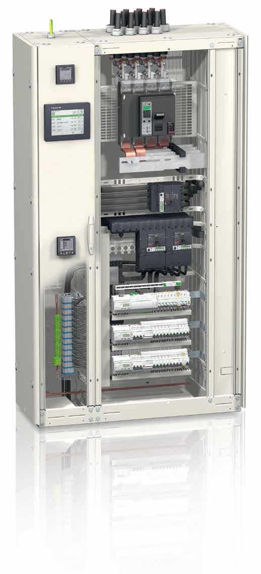
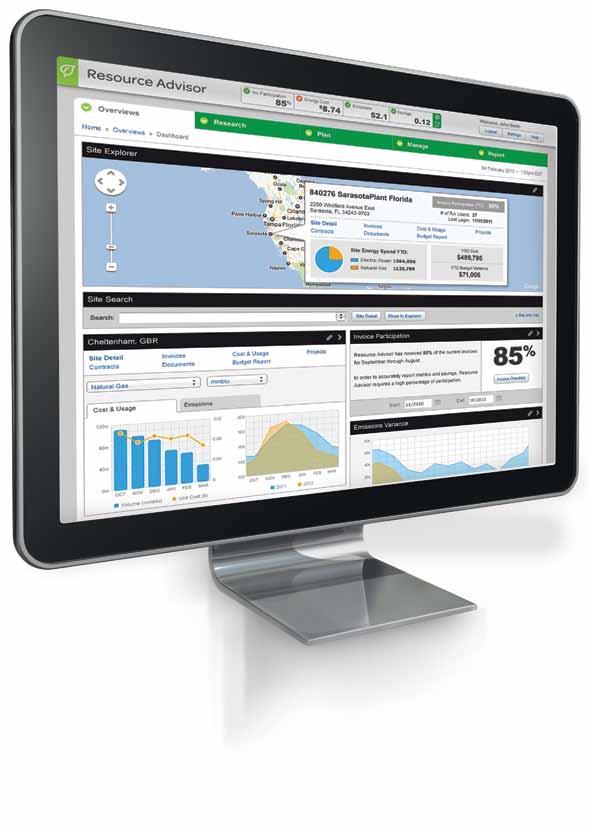
5 Measure 'Smart Panels' mean visible information Grouping and measuring most of the electrical protection, command and metering components, the switchboards are now significant sources of data locally displayed and sent via communication networks. CLOUD connect and ready to be linked to expertise Smart Panels use reliable, simple to install and use displays, and, Ethernet and Modbus interfaces on the Enerlin X communication system. Information is safely transmitted through most efficient networks: Modbus SL inside switchboards, between components Ethernet, on cable or WiFi, inside the building and connecting switchboards to computers Ethernet on DSL or GPRS, for access to on-line services by Schneider Electric Energy experts, wherever they are, are now able to provide advises based on permanently updated data of the building. Save CLOUD On-site real time monitoring and control On a touch screen display connected to Ethernet Shows essential electrical information and alarms concerning the electrical network, Allows control (open, close, reset ) of various equipments This touch screen is well appreciated for real time value checking and control, directly on the front panel of the main switchboard On a PC display with common browser Shows monitoring web pages hosted into the local Ethernet interfaces Alarm events generate automatic notifications Allows control (open, close, reset ) of various equipments Data displayed on graphics or recorded into files are of a great interest for optimizing the use of energy in the building. As an example, they definitely help validating the change of temperature settings, time scheduling in a Building Management System or other automated devices. On-line Energy Management services StruXureWare Energy Operation automates data collection via an open, scalable, and secure energy management information system. With the help of the Schneider Electric energy management services team, data is then turned into actionable information to enable customers to understand their facilities performance on an ongoing basis. Energy Operation leverages companies current investments in their existing systems, and can be used to communicate advanced results and performance to a broad audience for a shared understanding throughout the organization. Cloud based energy computing can also help analyze performance of multi site locations and optimize energy consumption. 5


6 All your energy data available via Ethernet with connected switchboards From conventional Common panel indicators only show a basic view of the reality. In today's context, this solution becomes inadequate, as advanced dashboards are required for energy efficiency and optimization. to connected measurement This dashboard is generated by a Schneider Electric online service hosted in a web server. Energy consumption, circuit protection status, equipment activity, are collected in every switchboard of the building for this purpose. Ethernet today is the most adapted media for carrying large amount of data between electrical distribution systems to either local touch screens or distant servers "IP connected" switchboards have become a key factor of evolution in energy management and continuity of service. 6


7 Ethernet connected switchboards Ethernet: > Widely used in buildings, easy to wire Ethernet network is widely distributed to multiple users in buildings. A simple RJ45 socket is required to connect each switchboard. > No additional installation and maintenance friendly Is also available in buildings and well appreciated by operators during operation and maintenance. > Access from any PC or Ethernet FDM128 monitor PC: with common Internet Browser FDM 128: installed on the front panel or at any remote location of the building Ethernet makes "Smart Grid ready" switchboards A new energy management > Interactions Generation - Consumption The Smart Grid principle creates fine interactions between consumers and facilities that produce and distribute energy. These interactions enable load shedding orders to non-critical electrical equipment. > Internet connection Switchboards and dispatch centers connected to the Internet will enable the development of this energy strategy. Ethernet and responsiveness of building automation greatly limit the impact on the operating availability of equipment. Centralised energy generation Utility network Consumers The major ecological stakes lead to new management of power consumption and the implementation of renewable energy sources (wind, solar, small hydro...). These measures should help to control the growth of demand in a sustainable manner. Residential Electric vehicles Distributed generation, back-up power Transmission Distribution Consumption Renewable energy plants Electric vehicles Commercial and industrial 7


8 Enerlin'X communication system By collecting circuit breakers' and actuators' status, electrical values and countings, Enerlin X provides a simple and reliable link to local displays and expert web portals. Enerlin X Combination of consistent gateways, interfaces and displays, to make web connected switchboards a reality. It s because Enerlin X collects basic and advanced data, that clear and relevant dashboards can be generated. A clear vision of measurements and trends makes Savings achievable with an efficient energy management. 8


, > error free cabling, fast connectiondisconnection, > space saving in the")
9 Numerous tests have been carried out in our labs in order to ensure a great confidence in the Enerlin X communication architectures. An illustrated technical guide describes step by step implementation of Enerlin X components in a standard Prisma enclosure. Cabling aspects are detailed, thus the effect of electrical disturbances on the communication signals is minimized. Smart Panel Communication switchboards assembly guide. Technical Guide ref. DESW051EN Enerlin X design is largely inspired from the professional s strongest expectations: > consistent functions grouped in the smart components (e.g. Acti 9 Smartlink), > error free cabling, fast connectiondisconnection, > space saving in the enclosure. The embedded web pages of Enerlin X gateways make setup and configuration tests simple and intuitive. Precise and wellordered project documentation is automatically generated for maintenance and future evolution purpose. Other pages are dedicated to simple and real time monitoring and control. 9
10 Lighting HVAC Exploitation, maintenance 10
11 Application examples 11

12 Energy monitoring of a group of bank branches The banking group wants to follow and reduce the power consumption of all its agencies. It wants to have dashboards for its daily tracking, available on PC from headquarters and agencies. All agencies do not have the same characteristics because of their geographical location, thermal quality of the building and their activity schedules. Hence, 3 groups of agencies will be created for differential monitoring. Each agency will be involved in a challenge in its group according to the criteria of consumption but preserving an acceptable quality of service (comfort maintained throughout the day). Once the anomalies (if any) are identified, recommendations will be given to the managers concerned,to enable the reduction of consumption. Specifications It requires the implementation of three main features: > > Daily measurement of energy consumption of each agency > > Breakdown by major uses (global, HVAC, lighting and other uses) > > Correlation depending on weather conditions and the temperature of the premises > > Centralization, logging, storing data > > Provision of responsible and agencies customizable daily dashboards 12


13 Lighting Inside a typical branch Stake: economical use, preserving occupant s comfort, in respect of regulation Design trends Building design Promote, take natural lighting into account. Lighting technology Use low-wattage lamps: fluorescent lighting, LED. Building automation Multiple lighting zones with individual automated control, depending on the presence, brightness, occupancy schedules, etc. HVAC Inside a typical branch Building design Building automation Provide adequate thermal insulation. Multiple zones with individual thermal regulation. The user s settings are restricted to ±3 C and ventilation stops by window switch. Functions implemented with a Smart Panel + online Energy services 1 Measure 2 connect 3 Save Metering electrical lighting energy The energy of the lighting circuits is monitored by means of a power meter. KWH Extract, send... the metering data to displays, energy specialized data servers. Interfaces for counters provide access to data via the Ethernet network. Display counting values Follow and analyze the trends in order to generate savings by optimizing the use of lighting. Ethernet LCD display shows values, browser on a PC shows trends, and more... Cloud 13

14 Energy monitoring of a group of bank branches Save The key for savings is reliable information on consumptions. The data of each branch is collected on a Schneider Electric server. Periodic dashboards are automatically generated and sent to the manager responsible for the energy efficiency of the company sites. Online services on Schneider Electric server is a well adapted solution for multi sites energy supervision. Distances between sites and their number is no longer a constraint, as a single contract can be provided for all. The choice is made to give access to the manager to all dashboards, including the possibility to customize some of them. The branch managers have access to simplified dashboards showing their local performance and their score on the national dashboard. Access is provided from a common Internet browser on a PC, protected by ID + password. This dashboard focuses on a single branch HVAC performance. It has been customized with 3 widgets: HVAC consumption, temperature, performance achieved compared to target. 14
15 Enerlin X configuration in a branch Ethernet Modbus Hard wired Internet Energy server Com X 200 Temperature sensors Acti 9 Smartlink Ethernet ict iact 24 iem2000t xc60 OF+SD24 Reflex ic60 iem3250 iem3250 Office lighting, commercial lighting: monitoring, control, metering. UPS main supply monitoring Air conditioning /Heating: monitoring, control, metering Incomer metering Lighting: 2 zones. Relays with manual override, monitored and controlled by iact24 auxiliary. One iem2000 impulse counter per zone CLOUD UPS: the main supply circuit breaker is monitored, the UPS alarm output can be also wired (not represented). An alarm is transmitted in case of tripping (or UPS fault). Air conditioning / heating: the power is established by means of a remote control circuit breaker during the scheduled opening periods of the branch. iem phase Modbus energy meter. Total energy consumption of the branch: by iem phase Modbus energy meter. Smartlink Ethernet ensures: > > monitoring the status of lighting, critical circuit breakers > > control of lighting zones, air conditioning / heater > > energy pulses counting > > communication with Com X200 energy server and potential building controller (time scheduling) Com X 200 ensures: > > temperature sensors acquisition > > data recording, logging (sensors + Smartlink) > > web pages generation > > GPRS communication with the web The locally generated web pages can be viewed through a simple PC browser. A server collects the energy data to be displayed in the global supervision dashboards. The shared access to energy data is based on 'Cloud computing' In principle, the data of each switchboard is transmitted on the web and stored in one or more remote and secure servers (the 'Cloud'). They are processed by Schneider Electric "Operation Energy Online" treatments: elaboration of energy challenge results, costs and savings on dashboards. These dashboards are provided on any PC connected to the web with an authorized identification. 15

16 Energy monitoring, asset management and maintenance of a hotel The hotel manager wants to: > > Preserve comfort by predictive and planned maintenance > > Minimize the discomfort caused by problems on critical equipment > > Measure electrical consumption, the volume of different fluids and their evolution > > Optimize the power consumption by a more appropriate use of equipment The manager wants energy dashboards on his PC to edit reports periodically. The system must detect and report problems on critical equipment > > Fire alarm Panel > > HVAC equipment > > Water Heaters > > Circuit breakers (feeders) Alarms must be reported by audible signal with designation on a monitor. Alarm must be generated when periodic maintenance of equipment is due. Volumes of fluids > > Gas > > Hot water > > Cold water Specifications Dashboards must be provided > > Energy consumption, evolution > > Volume of fluids, evolution > > Outside temperature, evolution Consumption must be measured > > Energy > > Global > > HVAC > > Lighting > > Rooms, per floor > > Water heaters > > Cooking and dishwashing equipment 16


17 maintenance Inside a hotel Stake: diagnose faults, preserve continuity of service Design trends Technology Choice of equipment with alarming outputs. Building automation Monitoring of available alarming outputs. Functions implemented with a Smart Panel + LCD display 1 Measure 2 connect 3 Save Operation alarms Tripping signals from circuit breakers, fault signals from fire alarm, boilers, air handling unit and chillers. Maintenance alarms On air handling operation time (filter replacement). Alarms transfer on Ethernet network Com X 200 Energy server sends alarm and related information on the hotel Ethernet network. Display of counting values and temperature The web pages are available on a dedicated LCD touch panel and on any PC on the hotel network with authorized access. 17
18 Stake: check correct operation, preserve the energy efficiency of the equipment in all weather condition. Building design High quality thermal insulation and air tightness Building automation Fully check correct operation, fine tune the thermal regulation parameters during the first season Air handling unit + Chillers consumption Stake: preserve energy efficiency in the rooms, measure gains obtained with low consumption equipment. Technology Low consumption mini bars and TV sets, LED lighting Guestroom energy consumption Stake: avoid waste, optimize usage, preserving occupant s comfort Building design Optimize hot water pipes length Technology Efficient boilers and dishwashers, water saving shower heads, tap aerators, dual flush toilets Hot water, cold water, gas Functions implemented with a Smart Panel + LCD display 1 Measure 2 connect 3 Save Metering per usage: total room consumption, air handling units, chillers consumptions From Energy meters Metering of volumes of water and gas From water, gas meter Recording of outside temperature From a 0-10 V temperature sensor kwh Transfer of metering data transfer on Ethernet network Com X 200 Energy server collects and saves the data. The transfer is provided via its Ethernet port to the hotel network. Display of counting values and temperature The web pages are available on a dedicated LCD touch panel and on any PC on the hotel network with authorized access. C m 3 18
19 Hotel application: Enerlin X communication diagram Temp Ethernet Modbus ULP Hard wired Energy server Com X 200 Chiller Air handling unit Lighting LV main switchboard Rooms floor 3 Rooms floor 1 Rooms floor 2 LV final switchboard LV main switchboard, grouping > > Main incomer > > Rooms circuits feeders (grouped per floor) > > Protection of HVAC circuits > > Protection of lighting > > Protection of and other circuits > > Kitchen feeder The Com X 200 Energy Server collects the signals from the outside temperature sensor, as well as the data from the energy meters and the main incomer status and electrical values (Compact NSX, via its Micrologic controller). The Acti 9 Smartlink Modbus collects the signals from various circuit breakers status contacts. LV final distribution switchboard, grouping > > Kitchen circuits breakers > > Water heaters circuit breakers Gas Gas meter Cold Hot water water 1 Water meters Hot water 2 Dishwashing Cooking equipment Technical room The Acti 9 Smartlink Ethernet collects the gas and water meter pulses, as well as the status of various modular circuit breakers. The Modbus network is used for collecting data from energy meters. 19
20 20
21 Smart Panel design 21
22 Locate sources of useful information in the switchboard Masterpact 1, Compact 2, circuit breakers Auxilliary contacts indicate breaker status. Embedded sensors provide electrical values. Status contacts and sensors are monitored by the embedded Micrologic control unit. Web pages generated by IFE interface + gateway Monitoring of electrical values - Breaker status Basic Readings: Micrologic H (Arch 1) (Micrologic H) Load Current (A) Power Voltage LL Voltage LN 1 Parameter Minimum Present Maximum Breaker Status Open Information for Maintenance Micrologic H (Arch 1) (Micrologic H) Breaker operation Counters Counters Value Total number of indication contacts (OF) operation 54 Indication contacts (OF) operation since last reset 54 Trip indication contact (SD) operation --- Fault trip indication contact (SDE) operation 78 Breaker operation Counters Counters Value Contact wear indicator --- % 2 Cradle Counters Counters Value Cradle connected 62 Cradle disconnected 20 Cradle test 7 22
 generated by Acti 9 Smartlink Ethernet Digital Channels 2 NAME STATUS CONTROL PRODUCT LABEL Lighting 1.1 OF+SD24 L1.")
23 Miniature circuit breakers, remote controlled MCB (Reflex), actuators (relays, impulse relays) 1 Auxiliary contacts indicate open/closed status. Specific input on actuators and Reflex ensures remote control. Web pages (partial) generated by Acti 9 Smartlink Ethernet Digital Channels 2 NAME STATUS CONTROL PRODUCT LABEL Lighting 1.1 OF+SD24 L1.1 Lighting 1.2 OF+SD24 L1.2 Lighting 2.1 OF+SD24 L2.1 Lighting 2.2 OF+SD24 L2.2 1 Lighting 2.3 OF+SD24 L2.3 Ventilation 1 OF+SD24 V1 2 2 Energy meters 2 Contact output sends a pulse every X Wh. Web pages (partial) generated by Acti 9 Smartlink Ethernet Monitoring energy meters Pulse Meters NAME VALUE PRODUCT LABEL Lighting kwh iem2000t L1 Lighting kwh iem2000t L2 Analog sensor 3 Temperature sensor sends a 0-10 V signal. 3 Web pages (partial) generated by Acti 9 Smartlink Ethernet Monitoring analog sensors Analog Channels NAME VALUE PRODUCT LABEL Outside temperature 18 C Crouzet Text 1 23
 A E P H Spring charged CH A E P H Ready to close A E P H Fault-trip SDE A E P H Connected / disconnected / test position CE/CD/CT (CCM only) A E P H")
24 Masterpact, Compact NS Measure & Connect: circuit breaker status and electrical values Available information and functions Micrologic A Micrologic E Micrologic P Micrologic H* Available functions Micrologic type Status indications ON/OFF (O/F) A E P H Spring charged CH A E P H Ready to close A E P H Fault-trip SDE A E P H Connected / disconnected / test position CE/CD/CT (CCM only) A E P H Controls MX open A E P H XF close A E P H Measurements Instantaneous measurement information A E P H Averaged measurement information E P H Maximeter / minimeter A E P H Energy metering E P H Demand for current and power E P H Power quality H Operating assistance Protection and alarm settings P H Histories E P H Time stamped event tables P H Maintenance indicators A E P H * Micrologic H: for Masterpact only Embedded trip unit and communication module Micrologic trip unit All Masterpact circuit breakers are equipped with a Micrologic trip unit. This adjustable unit is mainly designed for tripping the circuit breaker in case necessary and monitoring the downstream circuit. Alarms may be programmed for remote indications. Electrical measurements and operation data for predictive maintenance are provided for local display or distant monitoring. BCM ULP communication module This module provides an ULP communication port to a Micrologic trip unit, giving monitoring and control access from upper networks, Modbus or Ethernet. 24
25 24VDC 24VDC O1 13 I1 Enerlin X communication solutions functions Fixed Masterpact circuit breaker Drawout Masterpact circuit breaker Ethernet Modbus Ethernet Modbus BCM ULP ETH1 ETH2 IFE ETH1 ETH2 IFE_XX.YY.ZZ (factory set) ETH1 LK/10-100/ACT ETH2 LK/10-100/ACT Module Status Modbus-SL Network Status LV I J ETH1 ETH2 IFE ETH1 ETH2 IFE_XX.YY.ZZ (factory set) ETH1 LK/10-100/ACT ETH2 LK/10-100/ACT Module Status Modbus-SL Network Status LV I J OF, SDE microswitches COM terminal block (E1 to E6) MX and XF communicating voltage releases CE, CD and CT contacts Micrologic trip unit Breaker ULP cord or or I/O module IFE interface module ULP system ULP system + 24VDC I1 C I2 I3 C I4 I5 C I6 C I2 I3 C I4 I5 C I6 IFM module APP I1 A1 I2 I3 O1 I4 O2 I5 O3 I6 G G O2 O3 A T1 T2 IO Module H C MX1 XF D B G CD CE CT E A OF SD SDE PF CH C B MX1 - XF D F OF SDE PF CH A F ULP system is a fast communication link dedicated to circuit breaker monitoring and control. Based on a RS485 physical liaison with cable segments up to 5 meters, it is well adapted to severe environment. A choice of 6 preconnectorized cables with different length is provided. IFE interface: ULP to Ethernet interface module. Provides an IP address to any circuit breaker fitted with an ULP port. The IFE interface makes all available data from the circuit breaker accessible from an Ethernet compatible display (IFM128), a PC with common browser, or an Ethernet interface. IFE interface + gateway version generates its owns web pages. IFM: ULP to Modbus Interface module Makes all available data of a circuit breaker fitted with an ULP port accessible via a Modbus network. IFM acts as a Modbus slave, accessible from a Modbus master (IFE interface + gateway, Acti 9 Smartlink Ethernet or Com X 200). I/O: I/O application module I/O is dedicated to breakers with ULP liaison. It ensures the monitoring of the chassis position by means of CE, CD, CT contacts and control of applications around the circuit breaker (lighting or load control, cooling system, pulse metering acquisition...). 25
 A E Spring charged CH A E Ready to close A E Fault-trip SDE A E Connected / disconnected / test position CE/CD/CT (CCM only) A E Controls MX A E")


26 Compact NSX Measure & Connect: circuit breaker status and electrical values Available information and functions Micrologic trip units for 3 poles, 4 poles Compact circuit breakers Available functions Micrologic type Status indications ON/OFF (O/F) A E Spring charged CH A E Ready to close A E Fault-trip SDE A E Connected / disconnected / test position CE/CD/CT (CCM only) A E Controls MX A E Electrical motor mechanism A E Measurements Instantaneous measurement information A E Averaged measurement information E Maximeter / minimeter A E Energy metering E Demand for current and power E Power quality Operating assistance Protection and alarm settings Histories E Time stamped event tables Maintenance indicators A E Embedded trip unit and communication module Micrologic trip unit All Compact circuit breakers are equipped with a Micrologic trip unit. This adjustable unit is mainly designed for tripping the circuit breaker in case necessary hence monitoring the downstream circuit Alarms may be programmed for remote indications. Electrical measurements, operation data for predictive maintenance, are provided for local display or distant monitoring. BSCM module This module provides an ULP communication port to a Micrologic trip unit, giving monitoring and control access from upper networks, Modbus or Ethernet. 26
27 Enerlin X communication solutions functions Fixed Compact NSX circuit breaker Drawout Compact NSX circuit breaker Internal terminal block for communication via NSX cord BSCM module Micrologic trip unit Breaker ULP cord I/O module IFE interface module IFM module ULP system is a fast communication link dedicated to circuit breaker monitoring and control. Based on a RS485 physical liaison with cable segments up to 5 meters, it is well adapted to severe environment. A choice of 6 preconnectorized cables with different length is provided. IFE interface: ULP to Ethernet interface module. Provides an IP address to any circuit breaker fitted with an ULP port. The IFE interface makes all available data from the circuit breaker accessible from an Ethernet compatible display (IFM128), a PC with common browser, or an Ethernet interface. IFE interface + gateway version generates its owns web pages. IFM: ULP to Modbus Interface module Makes all available data of a circuit breaker fitted with an ULP port accessible via a Modbus network. IFM acts as a Modbus slave, accessible from a Modbus master (IFE interface + gateway, Acti 9 Smartlink Ethernet or Com X 200). I/O: I/O application module I/O is dedicated to circuit breaker with ULP liaison. It provides the monitoring and control of any application around the circuit breaker (lighting or load control, cooling system, pulse metering acquisition...). 27
28 Acti 9 Measure & Connect: equipment status and control, counter values Available information and functions Available functions Circuit Breaker Reflex C. B. Relay Pulse R. Pulse counter Analog sensor Status indications OPEN/CLOSE TRIPPED Controls Open Close Measurements Counter pulses (kwh, m 3, ) Analog value (temperature, CO 2, ) Maintenance counters Number of trippings Number of OPEN/CLOSE cycles Total period of operation of the load Monitoring auxiliaries and counters OF+SD24 iem2000t iem3110 Circuit breaker auxiliaries > > 24 V DC low-level contacts - CB open/closed position - CB tripping indication Energy counters > > DIN rail mounted > > Designed for metering active energy consumed by a single- or 3-phase electric circuit Control auxiliaries and Reflex circuit breaker iatl 24 Impulse relay auxiliary > > 24 V: - Command to impulse relay - Open/close impulse relay position > > 230 V command to impulse relay - Various configurable local and remote control combinations iact 24 Contactor auxiliary > > 24 V: - Command to contactor - Open/close contactor position > > 230 V command to contactor - Various configurable local and remote control combinations Reflex TM ic60 Monitoring and integrated control circuit breaker > > 24 V DC and 230 V AC - Command - Open/close - Tripping indication > > Various configurable local and remote control combinations 28
.")
29 Enerlin X communication solutions functions Acti 9 Smartlink Ethernet Ethernet Modbus Master xc60 OF+SD24 iatl24 Acti 9 circuit-breakers, pulse relays itl They are monitored or controlled by the I/O s via specific adaptors (OF+SD24 and iatl24). Reflex ic60 IEM2000T OUT 0-24 V DC Acti 9 remote controlled circuit-breakers, actuators, counters Reflex ic60, relays, energy meters with impulse output are directly connected V sensor or 4-20 ma Acti 9 Smartlink Ethernet > > 7 connectors: 2 inputs / 1 output / + 24 V DC per connector > > 1 connector with 2 analog 0-10 V or 4-20 ma inputs > > 1 connector for 24 V DC output Acti 9 Smartlink Ethernet provides a Modbus master port for a network collecting data from Acti 9 Smartlink Modbus or other Modbus slaves (counters, power meters ). It also provides an Ethernet gateway facility. Acti 9 Smartlink Modbus Modbus Slave Smartlink cables A standard connection design with the corresponding cables has been developed for error-free and fast cabling. Smartlink Ethernet > > 11 connectors: 2 inputs / 1 output / + 24 V DC per connector > > 1 connector for 24 V DC output Smartlink Modbus provides a Modbus slave interface facility for Acti 9 components. 29
 Smartlink Modbus Modbus Slave Energy")
30 Enerlin X gateways and interfaces connectivity Switch Interface to Ethernet IFE interface Ethernet gateways IFE interface + gateway Modbus Master Com X 200 Modbus Master Smartlink Ethernet Modbus Master Measure Connect Or I/O Interfaces to Modbus Compact IFM Modbus Slave Power meter PM3200 Modbus SL networks (one master per network, multiple slaves) Smartlink Modbus Modbus Slave Energy counter, Acti 9 circuit breakers and actuators... Masterpact Ethernet Modbus ULP Hard wired > > This diagram clearly shows the equipment involved into the "Measure" and "Connect" functionalities defining the Smart Panel concept > > Interface: provides a network port to one or several devices (circuit breakers, actuators, counters,...) from their hard wired or ULP links > > Gateway: ensures the communication between two networks with different protocols (Ethernet and Modbus) 30
31 Examples of connected switchboards architecture ULP Modbus Ethernet Hard wired Building Ethernet network Switch Switch Switch Switch Switch Switch DSL Modem DSL Modem Final distribution switchboards Small building Main switchboard Medium building Main switchboard Unique switchboard: Acti 9 Smartlink ensures the monitoring and control of circuit-breakers and actuators. A power meter (PM) shares the same Modbus network, the Compact circuit breaker is monitored through dry contacts. The Modbus master, an Acti 9 Smartlink Ethernet, collects the data from the Acti 9 Smartlink Modbus slave, and then sends all status and values to the Com X 200 energy server by an Ethernet liaison. The Com X 200 acts as a gateway, connecting the switchboard to the Cloud via a DSL modem. Display The related energy dashboards generated by the Energy Operation web services are available on any PC connected to the web. Main switchboard: Acti 9 Smartlink ensures the monitoring and control of circuit-breakers and actuators. The main incomer is monitored and controlled directly by the IFE interface + gateway, through an ULP link. Other circuit breakers are connected to IFM interfaces, through ULP links, as well. The data from the Acti 9 Smartlink Modbus slaves are collected by the master, an Acti 9 Smartlink Ethernet. The IFE interface concentrates the data from: > > the Acti 9 Smartlink s through a Ethernet liaison > > the IFM s through DIN rail connectors (see page 50) > > the main incomer through its ULP link Display As the choice was made for a local monitoring and control, an LCD touch panel IFM128 or PC with standard browser is connected to the building Ethernet network, shared by all the switchboards. The web pages generated by the local IFE interface and Acti 9 Smartlink Ethernet are displayed on it. Final distribution switchboards An Acti 9 Smartlink Ethernet ensures the connection of each switchboard to the local Ethernet network. The same principle as in the main switchboards applies for the status and values monitoring. 31
32 32
33 Enerlin'X components 33

34 Enerlin'X components Enerlin X communication system Products overview Enerlin'X communication system provides access to status, electrical values and devices control using Ethernet and Modbus SL communication protocols. Ethernet has become the universal link between switchboards, computers and communication devices inside the building. The large amount of information which can be transferred makes the connection of Enerlin'X digital system to hosted web services of Schneider Electric a reality. More advantages are offered to integrators thanks to configuration web pages available remotely or on the local Ethernet network. Modbus SL is the most widely used communication protocol in industrial networks. It operates in master-slave mode. The devices (slaves) communicate one after the other with a gateway (master). H D G G G G H C B F A E 4 E F Ethernet Modbus SL ULP Hard wired ULP is a fast communication link dedicated to circuit breaker monitoring and control. 34
 function Modbus Master Ethernet cable + WiFi 6 2 - EBX200 B FDM128 Ethernet LCD colour touch screen - Ethernet - - - FLV434128 C FDM121 LCD display")
35 Enerlin'X communication devices and displays Name Function Port Bin. Input (to device) (to server) Analog. Input Bin. Output Cial. Ref. A Com'X 200 Energy Server with Ethernet Gateway (1) function Modbus Master Ethernet cable + WiFi EBX200 B FDM128 Ethernet LCD colour touch screen - Ethernet FLV C FDM121 LCD display for circuit breaker ULP TRV00121 D IFE interface + gateway IFE interface Ethernet interface (2) & Gateway Ethernet interface for circuit breakers Modbus Master & ULP Ethernet LV ULP Ethernet LV E Acti 9 Smartlink Ethernet Ethernet interface with Input/Output functions & Gateway Modbus Master Ethernet A9XMEA08 F Acti 9 Smartlink Modbus Modbus interface with Input/Output functions - Modbus Slave A9XMSB11 G IFM Modbus interface for circuit breaker ULP Modbus Slave TRV00210 H I/O Input/Output application module for circuit breaker ULP ULP 6-3 LV (1) Gateway: transfers data from a network to another (ie.: Modbus to Ethernet). (2) Interface: transfers data from an equipment to a network.(ie.: ULP to Modbus). Plug and play commissioning tools give a real peace of mind to panel builders as their panels can be functionally checked before delivery. Commissioning / maintenance tools Web pages embedded into Com X 200 and Acti 9 Smartlink Ethernet gateways Access with a standard PC and common browser: commissioning communication diagnosis functional tests Electrical Asset Manager Loaded into a standard PC Error free commissioning. Time saving, easier management and maintenance thanks to the advanced services: project management configuration of controllers, gateways, test of communication networks, diagnostic report 35
 and environmental parameters such as temperatures,")

36 Enerlin'X components Energy Server Com'X 200 Functions and characteristics PB Energy Server Com'X 200. Ethernet GPRS data logger function The Energy Server Com'X 200 collects and stores wages consumptions (Water, Air, Gas, Electricity, Steam) and environmental parameters such as temperatures, humidity, and CO2 levels in a building. Data is periodically transmitted as a report to an internet database server. Data processing and display Once received by the server, the data is ready to be processed and displayed as web pages through web services provided by Schneider Electric, such as StruxureWare Energy Operation and StruxureWare Energy On Line. Energy Operation. Energy Online. or by any private energy management platform. Architecture Access to the web: choice of 3 media. PB PB Energy Server Com'X top view. Features From a simple metering installation with 1 device to large metering systems, Com'X 200 collects data from any Modbus TCP or serial devices, from any pulse meters, actuators and analogue sensors Automatic discovery of connected Modbus devices Connectivity to the cloud through Ethernet, Wi-Fi and GPRS 2 Ethernet ports to separate upstream cloud connection from field devices network Protocols: HTTP, HTTPS, FTP, SMTP with Proxy management Data export: Native connection to Schneider Electric Service platforms (Energy Operation, Energy Online) - CSV file export for other database servers Setup through convenient built-in web pages Compliant with electrical switchboard environment (Temperature, electro magnetic compatibility) Storage of data in case of communication failure Local backup of the configuration parameters When associated with SE Services: Remotely managed (firmware upgrade, configuration backup, troubleshooting, parameters setting GPRS contract management with SIM card provided Catalogue numbers Energy Server Com'X 200 Com'X 200 Ethernet data logger EBX 200 Wi-Fi USB stick EBXA-USB-WiFi GPRS modem with SIM card EBXA-GPRS-SIM GPRS modem without SIM card EBXA-GPRS External GPRS antenna EBXA-ANT-5M 36
.")
 IEC 62053-31 Class A Provided by Com'X 200: 12 V DC 60 ma External: from 10 to 30 V DC PT100 PT1000 2-wires probes (accuracy 1%) Sensors with 4-20 ma or 0-10")
 Provided by Com'X 200: 24 V DC - 50 ma per input 1 RS485 Modbus serial port, RJ45 connector, for 32 Modbus components maximum 2 Ethernet ports RJ45 10/100 Base, DPWS ready PoE class 3 (802.")
37 PB PB PB PB Energy Server Com'X 200. Energy Server Com'X 200 with the front face in Open position, GPRS modem and Wi-Fi USB stick are connected. GPRS modem (antenna in folded position). Ethernet GPRS data logger Characteristics Inputs 6 Digital inputs Max impulse frequency Power Supply 2 Analogue inputs Sensor compatibility Power supply Communication Meter Network Configuration / Data transfer 25 Hz (min duration 20 ms) IEC Class A Provided by Com'X 200: 12 V DC 60 ma External: from 10 to 30 V DC PT100 PT wires probes (accuracy 1%) Sensors with 4-20 ma or 0-10 V output (accuracy 0.5%) Provided by Com'X 200: 24 V DC - 50 ma per input 1 RS485 Modbus serial port, RJ45 connector, for 32 Modbus components maximum 2 Ethernet ports RJ45 10/100 Base, DPWS ready PoE class 3 (802.3af), DHCP client DHCP client or server IPv4, IPv6 HTTP, HTTPS, Modbus TCP/IP Ethernet 1 Ethernet 2 Protocols USB Ports 2 For memory stick USB port on front face For Wi-Fi stick USB port 2 behind cover LED indicators 11 Power/ Boot status GPRS modem status and signal level Modbus communication Ethernet communication Wi-Fi communication mode (Access point / Infrastructure) and status Digital inputs status and pulse reception Power Supply AC V (+/- 15%)(50-60Hz) DC 24 V (+/- 10%) Max power 26 W max Mechanical IP Front face IP40, terminals IP20 Dimensions (HxWxD) 91 x 144 x 65.8 mm Weight 450 g Environment Operating temperature -25 to +60 C (-13 to +140 F) Storage temperature -40 to +85 C (-40 to +185 F) Humidity 5 to 95% relative humidity (without condensation) at +55ºC Pollution Class III Safety standards / regulation International (CB scheme) IEC USA UL508 Canada culus 508 Europe EN Quality Brands CE, UL External GPRS antenna. PB Wi-Fi USB stick 37


38 Enerlin'X components FDM128 Ethernet switchboard display For Masterpact, Compact, Powerpact* circuit breakers and Acti 9 Smartlink PB PB PB Micrologic measurement capabilities come into full play with the FDM128 switchboard display. It connects to Ethernet communication via RJ45 port and displays Micrologic information. The result is a true integrated unit combining a circuit breaker and a Power Meter. Additional operating assistance functions can also be displayed. FDM128 display. Surface mount accessory. FDM128 The FDM128 is an 'intelligent' Ethernet display. It collects the data from up to 8 devices via the Ethernet network: circuit breakers, as Masterpact, Compact, or Powerpact*, individually via their Ethernet interfaces or gateways modular circuit breakers, actuators, counter and analog sensors when they are grouped an connected to an Acti 9 Smartlink interface FDM128 generates and displays a dedicated page for each one, with the monitored status, values, and the potential controls. Masterpact and Compact monitoring and control The FDM128 is intended to display the data of a Micrologic A/E/P/H trip unit embedded into a Masterpact or Compact. They consist of electrical measurements, trips and operating information. Protection setting cannot be modified from the FDM128. Measurements may be easily accessed via a menu. Trips are automatically displayed. A pop-up window displays the time-stamped description of the trip. Status indications As long as the circuit breaker is equipped with a BCM ULP or BSCM communication module and the appropriate status contacts (with or without Micrologic), a minimum of information can be displayed: O/F: ON/OFF SDE: Fault-trip indication (overload, short-circuit, ground fault) PF: ready to close CH: charged (spring loaded) CE, CD, CT cradle management with I/O application module Remote control When the circuit breaker is equipped with a BCM ULP or BSCM communication module (including their kit for connection to XF and MX communication voltage releases), the FDM128 display can also be used to control (open/close) the circuit breaker. Two operating modes are available: local mode: open/close commands are enabled from FDM128 while disable from the communication network remote mode: open/close commands are disabled from FDM128 while, enabled from communication network. Acti 9 Smartlink monitoring and control The FDM128 can display all status, counting and analog values collected in hard wired devices by an Acti 9 Smartlink interface. It can also provide potential controls. Wired devices: Circuit breakers Energy counters Analog sensors Relays, impulse relays Monitoring O/F auxiliary contacts: ON/OFF status. SD auxiliary contacts: fault-trip indication (overload, short-circuit, ground fault). Counters: values.analog sensors: (temperature value, humidity,...) Remote control Circuit breakers with tripping auxiliary, relays, impulse relays, Acti 9 Reflex remote control circuit breakers. Main characteristics x 86.4 mm with 5.7" QVGA display 320 x 240 pixels Color TFT LCD, LED backlight Wide viewing angle: vertical ±80, horizontal ±70 High resolution: excellent reading of graphic symbols Operating temperature range -10 C to +55 C CE / UL / CSA marking (pending) 24 V DC power supply, with tolerances 24 V (limit V DC) Consumption y 6.8 W *Except Powerpact M 38
39 DB :00:05 Mounting The FDM128 is easily installed in a switchboard. Standard door hole Ø 22 mm The FDM128's degree of protection is IP65 in the front and IP54 at the back. Connection The FDM128 is equipped with: a 24 V DC terminal block: power supply range of 24 V DC (limit V DC) The FDM128 display unit has a 2-point screw connector on the rear panel of the module for this purpose. one RJ45 Ethernet jacks The Micrologic connects to the internal communication terminal block on the Masterpact via the breaker ULP cord and Ethernet connection through IFE interface. Navigation Touch screen is used for intuitive and fast navigation. The user can select the display language (Chinese, English, French, German, Italian, Portuguese, Spanish, etc.). Screens Main menu S1-1 - Lighting/Level1 DB DB Quick view Product ID Information Reset all Counter Measures Operation xxx Alarm history Trip SDE xxx Control Close command xxx Maintenance ESC 3/3 Product identification :00:05 S1-1 - Lighting/Level1 Quick view Measures Alarm history Control Maintenance ESC Energy Ep Eq Es 6/7 Metering: meter kwh 257 kvarh kvah :00:05 Quick view Metering Control Alarms Maintenance When not in use, the screen is automatically shifted to low back-lighting. Fast access to essential information b b"quick view" provides access to five screens that display a summary of essential operating information (I, U, f, P, E, THD, circuit breaker On / Off) Access to detailed information b b"metering" can be used to display the measurement data (I, U-V, f, P, Q, S, E, THD, PF) with the corresponding min/max values Alarms displays the trip history Services provides access to the operation counters, energy and maximeter reset function, maintenance indicators, identification of modules connected to the internal bus and FDM128 internal settings (language, contrast, etc.) Communication components and FDM128 connections S1-1 - Lighting/Level1 Quick view Measures Alarm history Control Maintenance ESC Product ID Information Reset all Load profile 0 to 49% 50 to 79% 80 to 89% 90 to 100% 2/3 Services. 39
 via a breaker ULP cord and displays Micrologic information. The result is a true integrated unit combining a circuit breaker and a Power Meter.")


40 Enerlin'X components FDM121 switchboard display For Masterpact, Compact, Powerpact* circuit breakers PB PB PB Micrologic measurement capabilities come into full play with the FDM121 switchboard display. It connects to COM option (BCM ULP) via a breaker ULP cord and displays Micrologic information. The result is a true integrated unit combining a circuit breaker and a Power Meter. Additional operating assistance functions can also be displayed. FDM121 display. Surface mount accessory. Connection with FDM121 display unit. FDM121 switchboard display An FDM121 switchboard display unit can be connected to a circuit breaker via an ULP cord to display all measurements, alarms, histories and event tables, maintenance indicators, management of installed devices on a screen. The result is a veritable 96 x 96 mm Power Meter. The FMD121 display unit requires a 24 V DC power supply. The FDM121 is a switchboard display unit that can be integrated in the Compact NSX100 to 630 A, Compact NS or Masterpact systems. It uses the sensors and processing capacity of the Micrologic trip unit. It is easy to use and requires no special software or settings. It is immediately operational when connected to the Compact NSX by a simple cord. Also, it provides monitoring and control with the use of the I/O application module, the motor mecanism module, or the Breaker Status module. The FDM121 is a large display, but requires very little depth. The anti-glare graphic screen is backlit for very easy reading even under poor ambient lighting and at sharp angles. Display of Micrologic measurements and alarms The FDM121 is intended to display Micrologic 5 / 6 measurements, alarms and operating information. It cannot be used to modify the protection settings. Measurements may be easily accessed via a menu. All user-defined alarms are automatically displayed. The display mode depends on the priority level selected during alarm set-up: high priority: a pop-up window displays the time-stamped description of the alarm and the orange LED flashes medium priority: the orange "Alarm" LED goes steady on low priority: no display on the screen All faults resulting in a trip automatically produce a high-priority alarm, without any special settings required. In all cases, the alarm history is updated. Micrologic saves the information in its non-volatile memory in the event of an FDM121 power failure. Status indications and remote control When the circuit breaker is equipped with the Breaker Status Module, the FDM121 display can also be used to view circuit breaker status conditions: O/F: ON/OFF SD: trip indication SDE: Fault-trip indication (overload, short-circuit, ground fault) When the circuit breaker system is equipped with the I/O application module, the FDM121 can monitor and control: craddle management circuit breaker operation light and load control custom application When the circuit breaker system is equipped with the motor mechanism module, the FDM121 offers remote closing and opening control. Main characteristics 96 x 96 x 30 mm screen requiring 10 mm behind the door (or 20 mm when the 24 V power supply connector is used) White backlighting Wide viewing angle: vertical ±60, horizontal ±30 High resolution: excellent reading of graphic symbols Alarm LED: flashing orange for alarm pick-up, steady orange after operator reset if alarm condition persists Operating temperature range -10 C to +55 C CE / UL / CSA marking (pending) 24 V DC power supply, with tolerances 24 V -20 % (19.2 V) to 24 V +10 % (26.4 V) When the FDM121 is connected to the communication network, the 24 V DC can be supplied by the communication system wiring system. Consumption 40 ma Mounting The FDM121 is easily installed in a switchboard. Standard door cut-out 92 x 92 mm Attached using clips To avoid a cut-out in the door, an accessory is available for surface mounting by drilling only two 22 mm diameter holes. The FDM121 degree of protection is IP54 in front. IP54 is maintained after switchboard mounting by using the supplied gasket during installation. Connection The FDM121 is equipped with: a 24 V DC terminal block: vvplug-in type with 2 wire inputs per point for easy daisy-chaining vv power supply range of 24 V DC -20 % (19.2 V) to 24 V DC +10 % (26.4 V) A 24 V DC type auxiliary power supply must be connected to a single point on the ULP system. The FDM121 display unit has a 2-point screw connector on the rear panel of the module for this purpose. The ULP module to which the auxiliary power supply is connected distributes the supply via the ULP cable to all the ULP modules connected to the system and therefore also to Micrologic. 40
41 two RJ45 jacks The Micrologic connects to the internal communication terminal block on the Masterpact via the breaker ULP cord. Connection to one of the RJ45 connectors on the FDM121 automatically establishes communication between the Micrologic and the FDM121 and supplies power to the Micrologic measurement functions. When the second connector is not used, it must be fitted with a line terminator. DB I1 I3 % % ESC I 310 A I2 % 302 A IN % 315 A 23 A 1 Escape 2 Down 3 OK 4 Up 5 Context 6 Alarm LED Navigation Five buttons are used for intuitive and fast navigation. The "Context" button may be used to select the type of display (digital, bargraph, analogue). The user can select the display language (Chinese, English, French, German, Italian, Portuguese, Spanish, etc.). Screens When powered up, the FDM121 screen automatically displays the ON/OFF status of the device Main menu DB DB Produit Id Micrologic 5.3A Serial number: P07451 Part number: LU Firmware: 1.02 ESC Product identification. NonResettableEnergy 1/ kwh EpIN EpOut kwh ESC DB DB Metering I U-V PQS E F - PF - cos Φ ESC OK Metering: sub-menu. Load Profile 2/ % 610 H % 15 H % 360 H % 3 H ESC Quick view Metering Control Alarms Maintenance When not in use, the screen is not backlit. Backlighting can be activated by pressing one of the buttons. It goes off after 3 minutes. Fast access to essential information b b"quick view" provides access to five screens that display a summary of essential operating information (I, U, f, P, E, THD, circuit breaker On / Off) Access to detailed information b b"metering" can be used to display the measurement data (I, U-V, f, P, Q, S, E, THD, PF) with the corresponding min/max values Alarms displays active alarms and the alarm history Services provides access to the operation counters, energy and maximeter reset function, maintenance indicators, identification of modules connected to the internal bus and FDM121 internal settings (language, contrast, etc.) Communication components and FDM121 connections Metering: meter. Services. DB DB External power supply 24 V DC - + Modbus-SL A External power supply 24 V DC - + Ethernet B D0 = A / Rx-, A / Tx- D1 = B / Rx+, B / Tx+ 24VDC ETH1 ETH2 1.3 m IFM D IFE D E OR E C Red Black White Blue F C Red Black White Blue F LV LV LV E1 E2 E3 E4 E5 E6 E1 E2 E3 E4 E5 E6 Breaker ULP cord Connections Masterpact is connected to the ULP devices (FDM121 display, IFM, IFE interface or I/O) unit via the breaker ULP cord. vv cord available in three lengths: 0.35 m, 1.3 m and 3 m vv lengths up to 10 m possible using extensions 24 V 0 V A / Tx - D0 B / Tx + D1 A / Rx - D0 B / Rx + D1 Customer terminal block A Modbus network B Ethernet network C Breaker ULP cord 24 V D FDM121 display E ULP termination F ULP cable 0 V A / Tx - D0 B / Tx + D1 A / Rx - D0 B / Rx + D1 Customer terminal block 41


42 Enerlin'X components IFE interface, IFE interface + gateway: Ethernet interface, gateway DB PB DB IFE interface, ref.: LV IFE interface + gateway, ref.: LV IFE interface, IFE interface + gateway description Introduction The IFE interface and IFE interface + gateway enable LV circuit breakers such as Masterpact and Compact, to be connected to an Ethernet network IFE interface: ref. LV Provides an Ethernet access to a single LV circuit breaker. Function Interface - one circuit breaker is connected to the IFE interface via its ULP port. IFE interface + gateway: ref. LV Provides an Ethernet access to one or several LV circuit breakers. Functions Interface - one circuit breaker is connected to the IFE interface via its ULP port Gateway: several circuit breakers on a Modbus network are connected via the IFE interface + gateway master Modbus port IFE interface, IFE interface + gateway features Dual 10/100 Mbps Ethernet port for simple daisy chain connection. Device profile web service for discovery of the IFE interface, IFE interface + gateway on the LAN ULP compliant for localization of the IFE interface in the switchboard Ethernet interface for Compact, Masterpact and Powerpact* circuit breakers Gateway for Modbus-SL connected devices (IFE interface + gateway only) Embedded set-up web pages Embedded monitoring web pages Embedded control web pages Built-in alarm notification Mounting The IFE interface, IFE interface + gateway are DIN rail mounting devices. A stacking accessory enables the user to connect several IFMs (ULP to Modbus interfaces) to an IFE interface + gateway without additional wiring. 24 V DC power supply The IFE interface, IFE interface + gateway must always be supplied with 24 V DC. The IFMs stacked to an IFE interface + gateway are supplied by the IFE interface + gateway, thus it is not necessary to supply them separately. It is recommended to use an UL listed and recognized limited voltage/limited current or a class 2 power supply with a 24 V DC, 3 A maximum. IFE interface, IFE interface + gateway firmware update The firmware can be updated using: FTP customer engineering tool Required circuit breaker communication modules The connection to IFE interface or IFE interface + gateway requires a communication module embedded into the circuit breaker: Compact NS, Powerpact P, Powerpact R: BCM ULP communication module Compact NSX: NSX cord and/or BSCM module Masterpact NT/NW or Compact NS, Powerpact P, Powerpact R (Fixed electrically operated): BCM ULP communication module Drawout Masterpact NT/NW or a withdrawable Compact NS, Powerpact P, Powerpact R: BCM ULP and its respective I/O (Input/Output) application module. All connection configurations for Masterpact NT/NW, Compact NS, Powerpact P, Powerpact R require the breaker ULP cord. The insulated NSX cord is mandatory for system voltages greater than 480 V AC. When the second ULP RJ45 connector is not used, it must be closed with an ULP terminator (TRV00880). *Except Powerpact M 42
43 DB I IFE T H A B J K G 24VDC ETH1 ETH2 ETH1 ETH2 IFE-XX.YY.ZZ (factory set) ETH1 LK/10-100/ACT ETH2 LK/10-100/ACT Module Status Modbus-SL Network Status LV R C D E F General characteristics Environmental characteristics Conforming to standards UL 508, UL 60950, IEC 60950, Certification cuius, GOST, FCC, CE Ambient temperature -20 to +70 C (-4 to +158 F) Relative humidity 5 85 % Level of pollution Level 3 Flame resistance ULV0 Mechanical characteristics Shock resistance 1000 m/s2 Resistance to sinusoidal vibrations -5 Hz < f < 8.4 Hz Electrical characteristics Resistance to electromagnetic discharge Conforming to IEC/EN Immunity to radiated fields 10 V/m Immunity to surges Conforming to IEC/EN Consumption 120 ma at 24 V input Physical characteristics Dimensions 72 x 105 x 71 mm (2.83 x 4.13 x 2.79 in.) Mounting DIN rail Weight g (0.41 lb) Degree of protection of the installed I/O application module On the front panel (wall mounted enclosure): IP4x Connectors: IP2x Other parts: IP3x Connections Screw type terminal blocks Technical characteristics - 24 V DC power supply Power supply type Regulated switch type Rated power 72 W Input voltage V AC for single phase V AC phase-to-phase PFC filter With IEC Output voltage 24 V DC Power supply out current 3 A Note: it is recommended to use an UL listed/ul listed recognized limited voltage/limited current or a class 2 power supply with a 24 V DC, 3 A maximum. L A Ethernet 1 and Ethernet 2 communication port. B 24 V DC power supply terminal block C Ethernet communication LEDs: yellow: 10 Mb green: 100 Mb D Module status LED: steady off: no power steady green: device operational steady red: major fault flashing green: standby flashing red: minor fault flashing green/red: self-test E Network status LED: steady off: not power/no valid IP address steady green: connected, valid IP address steady orange: default IP address steady red: duplicated IP address flashing green/red: Self-test F Sealable transparent cover G ULP status LED H Test button (accessible closed cover). I Locking pad J Modbus traffic status LED (LV only) K Device name label L ULP ports IFE interface, IFE interface + gateway web page description Monitoring web page Real time data 67 Device logging Control web page Single device control Diagnostics web page Statistics Device information IMU information Read device registers Communication check Maitenance web page Maintenance log Maintenance counters Setup web page Device localization/name Ethernet configuration (dual port) IP configuration Modbus TCP/IP filtering Serial port Date and time server configuration Alarms to be ed Device list Device logging Device log export SNMP parameters Documentation links Preferences Advanced services control User accounts Web page access b b b b b b b b b b b b b b b b b b b b b b b b b b b b b b b b b b b b b b b b b b b b b b b b b b b b b b 43

.")
44 Enerlin'X components Acti 9 Smartlink DB e IEC/EN Acti 9 Smartlink Modbus Slave and Acti 9 Smartlink Ethernet are used to transfer data from Acti 9 devices to a PLC or monitoring system via the communication system: Modbus serial line for Acti 9 Smartlink Modbus Slave Modbus Ethernet TCP/IP or http for Acti 9 Smartlink Ethernet PB DB Functions Data transmission between the network and Acti 9 devices Circuit breakers, residual current circuit breakers, residual current devices: vvopen/closed state vvtripped state vvnumber of opening/closing cycles vvnumber of tripping actions Contactors, impulse relays: vvopening control vvclosing control vvopen/closed state vvnumber of opening/closing cycles vvtotal period of operation of the load (device closed). Remote controlled circuit breaker/reflex ic60: vvopening control vvclosing control vvopen/closed state vvtripped state vvnumber of opening/closing cycles vvtotal period of operation of the load Power meters: vvnumber of pulses recorded vvpulse value setting (e.g. kwh) vvtotal consumption recorded vvestimate of power consumption Analog sensors only for Acti 9 Smartlink Ethernet: vvtemperature sensor vvhumidity sensor vvco 2 detector vvoptical detector DB DB Acti 9 Smart Test software Electrical continuity test Functional testing of the devices Report printing Printing of a simplified diagram Project archiving Compatible with Windows XP, Windows 7, Windows 8 To be downloaded from Schneider Electric websites: vvschneider-electric.com or vvschneider-electric country web site All the data are stored in memory: number of cycles, consumption, period of operation, even in the event of a power failure. Acti 9 Smartlink can also exchange data with any device having 24 V DC digital inputs/outputs. No configuration of the connected products is required. When Acti 9 Smartlink is switched on, communication automatically adjusts to the Modbus Master or Ethernet (PLC, control station) communication parameters. Installation Mounting in switchboards: vvwidth 24 modules per row vvminimum spacing between rails 150 mm Mounting on vvdin rail, with mounting kit A9XMFA04 vvlinergy FM 80 A, with locking clips supplied vvlinergy FM 200 A, wtih mounting kit A9XM2B04 Test The communication and cabling test for the connected devices can be performed using Acti 9 Smart Test software 44
45 PB PB DB PB Acti 9 Smartlink Modbus Slave Acti 9 Smartlink Ethernet 24V Q I2 I1 0V A9XCAU06 PB PB PB Catalogue numbers Acti 9 Smartlink Type Set of Acti 9 Smartlink Modbus Slave 1 A9XMSB11 Supplied with Modbus connector 1 24 V DC power supply connector 1 Locking clips for mounting on Linergy FM 80 2 Acti 9 Smartlink Ethernet 1 A9XMEA08 Supplied with Connector for 4-point analog output 1 Modbus connector 1 24 V DC power supply connector 1 Locking clips for mounting on 2 Linergy FM 80 Accessories USB cable link / Modbus for Acti 9 Smartlink test 1 A9XCATM1 Prefabricated cables With 2 connectors Short: 100 mm 6 A9XCAS06 Medium-sized: 160 mm 6 A9XCAM06 Long: 870 mm 6 A9XCAL06 With 1 connector Long: 870 mm 6 A9XCAU06 Connectors 5-pin connectors (Ti24) 12 A9XC2412 Mounting kit DIN rail (4 feet, 4 straps, 4 adapters) 1 A9XMFA04 Linergy FM 200 A (4 adapters) 1 A9XM2B04 Spare parts Lock for Linergy FM 80 A (2 clips) 1 A9XMLA02 Connectable devices With Ti24 interface Type Reference Description iact24 A9C15924 Low-level control and indication auxiliary for ict contactors iatl24 A9C15424 Low-level control and indication auxiliary for itl impulse relays OF+SD24 A9N26899 Low-level indication auxiliary for C60, C120, DPN, RCCB/ID, C60H-DC Reflex ic60 See module CA Reflex ic60 with Ti24 interface Without Ti24 interface Power meters with pulse output, e.g. IEM2000T Impulse meters complying with the IEC standard 24 V DC indicator lamps, Harmony XVL range All loads not exceeding 100 ma, 24 V DC Light sensitive switches: example IC2000 Timers, thermostats, time switches, load shedding devices All 24 V DC auxiliary contacts, IEC type 1 With analog outputs Temperature and humidity sensors, with a 0-10 V or 4-20 ma output CO 2 and optical detectors, with a 0-10 V or 4-20 ma output 45
46 Enerlin'X components Acti 9 Smartlink (cont.) Common technical characteristics Power supply Rated 24 V DC ± 20 % Maximum input current 1.5 A Maximum inrush current 3 A Meter Capacity Input characteristics 2 32 pulses per input Number of channels Acti 9 Smartlink Modbus Slave 11 of 2-input channels Acti 9 Smartlink Ethernet 7 of 2-input channels Type of input Current collector Type 1 IEC Maximum cable length 500 m Rated voltage 24 V DC Voltage limits 24 V DC ± 20 % Rated current 2.5 ma Maximum current 5 ma Filtering time In state 1 2 ms In state 0 2 ms Isolation No isolation between channels Negative sequence voltage protection Yes Output characteristics Number of output channels Acti 9 Smartlink Modbus Slave 11 Acti 9 Smartlink Ethernet 7 Type of output 24 V DC 0.1 A current source Maximum cable length 500 m Rated voltage Voltage 24 V DC Maximum current 100 ma Filtering time In state 1 2 ms In state 0 2 ms Voltage drop (voltage in state 1) 1 V max Maximum inrush current 500 ma Leakage current 0.1 ma Overvoltage protection 33 V DC Environmental characteristics Temperature Operating -25 C C (if vertical mounting, limited to 50 C) Storage -40 C +80 C Tropicalization Treatment 2 (relative humidity of 93% at 40 C) Resistance to voltage dips 10 ms, class 3 as per IEC Degree of protection IP20 Pollution degree 3 Altitude Operating m Vibration resistance As per IEC g / ± 3.5 mm - 5 Hz to 300 Hz - 10 cycles Shock resistance As per IEC g / 11 ms Immunity to electrostatic discharge As per IEC Air: 8 kv Contact: 4 kv Immunity to radiated magnetic fields As per IEC V/m - 80 MHz to 3 GHz Immunity to fast transients As per IEC kv for inputs/outputs and Modbus communication. 2 kv for 24 DC power supply - 5 khz khz Immunity to conducted magnetic fields As per IEC V from 150 khz to 80 MHz Immunity to magnetic fields at mains frequency As per IEC A/m Resistance to corrosive atmospheres As per IEC Level 3C2 on H 2 S / SO 2 / NO 2 / Cl 2 Fire resistance For live parts At 960 C 30 s / 30 s as per IEC and IEC For other parts At 650 C 30 s / 30 s as per IEC and IEC Salt spray test As per IEC Severity 2 Environment In compliance with the RoHS directive Additional characteristics Duration of saving memory 10 years Prefabricated cables characteristics Dielectric resistance 1 kv / 5 min Minimum draw-out resistance 20 N 46
47 Acti 9 Smartlink Modbus Slave technical characteristics Characteristics of the Modbus link Link Modbus, RTU, RS485 serial connection Transmission Transfer rate 9600 baud baud, self-adaptable Medium Shielded cable, double twisted pair Protocol Master/Slave Type of device Slave Modbus addressing range 1 to 99 Maximum length of the bus 1000 m Type of bus connector 4-pin connector Acti 9 Smartlink Ethernet technical characteristics Characteristics of the Ethernet link Link Protocol Address mode Characteristics of Gateway Protocol Modbus slave number 8 Modbus addressing range 1 to 247 Characteristics of the Modbus Master link 10/100 MB Ethernet Modbus TCP server http (Web pages) Static and dynamic (supplied, by default, in dynamic mode) Modbus TCP/IP Modbus SL Link Modbus serial connection, RTU, RS485 Transmission Transfer rate 9600 baud baud, self-adaptable Support Shielded cable, double twisted pair Maximum length of the bus 1000 m Type of bus connector 4-pin connector Characteristics of the analog inputs Number 2 Type Separate configuration for each input, either 0-10 V or 4-20 ma Measuring accuracy 1/100 full scale Resolution 12 bits Acquisition time 500 ms Isolation No isolation between channels Power supply 0-24 V DC Type of cable Shielded cable, double twisted pair Maximum cable length 30 m Protection Short-circuit protection Dimensions (mm) DB DB Acti 9 Smartlink Modbus Slave Acti 9 Smartlink Ethernet Weight (g) Acti 9 Smartlink Type Acti 9 Smartlink Modbus Slave 195 Acti 9 Smartlink Ethernet
 PB107753-175 PB113286-175 Ti24 connector 7 input/output channels Protected at input against voltage reversals Protected at output by current limiting Pin 1: 0 V Pin 2: I1 Input 1 Pin 3: I2 Input 2")
48 Enerlin'X components Acti 9 Smartlink (cont.) PB PB Ti24 connector 7 input/output channels Protected at input against voltage reversals Protected at output by current limiting Pin 1: 0 V Pin 2: I1 Input 1 Pin 3: I2 Input 2 Pin 4: Q Output Pin 5: +24 V DC Analog connector 2 configurable input points, either 0-10 V or 4-20 ma Pin1: 0 V Pin2: AI1 Input 1 Pin3: AI2 Input 2 Pin4: +24 V DC Ti24 connector 11 input/output channels Protected at input against voltage reversals Protected at output by current limiting Pin 1: 0 V Pin 2: I1 Input 1 Pin 3: I2 Input 2 Pin 4: Q Output Pin 5: +24 V DC Acti 9 Smartlink Ethernet 24 V DC power supply connector Protected against voltage reversals Pin1: 0 V Pin2:+24 V DC Acti 9 Smartlink Modbus Slave 24 V DC power supply connector Protected against voltage reversals Pin1: 0 V Pin2:+24 V DC Ethernet connector 100 base T - RJ45 Signalisation Indication of operation of the communication system and the state of Acti 9 Smartlink Ethernet Serial port connector Modbus RS485 (Master) Pin1: D1 Modbus Pin2: D0 Modbus Pin3: shielding Pin4: common/0v Serial port connector RS485 Modbus (Slave) Pin 1: D1 Modbus Pin 2: D0 Modbus Pin 3: shielding Pin 4: common/0 V Signalisation Indication of operation of the communication system and the state of Acti 9 Smartlink Modbus Slave Thumbwheels Definition of the address in the Modbus network 48

49 PB
50 Enerlin'X components IFM Modbus communication interface PB Function A IFM - Modbus communication interface - is required for connection of a Masterpact or Compact to a Modbus network as long as this circuit breaker is provided with a ULP (Universal Logic Plug) port. The port is available respectively on a BCM ULP or BSCM embedded module. The IFM is defined as an IMU (Intelligent Modular Unit) in the ULP connection System documentation. Once connected, the circuit breaker is considered as a slave by the Modbus master. Its electrical values, alarm status, open/close signals can be monitored or controlled by a Programmable Logic Controller or any other system. IFM Modbus communication interface. Ref.: TRV Characteristics ULP port 2 RJ45 sockets, internal parallel wiring. Connection of a single circuit breaker (eventually via its I/O application module) A ULP line terminator or an IFM121 display unit must be connected to the second RJ45 ULP socket The RJ45 sockets deliver a 24 V DC supply fed from the Modbus socket. Built-in test function, for checking the correct connection to the circuit breaker and IFM121 display unit. Modbus slave port Top socket for screw-clamp connector, providing terminals for: vv24 V DC input supply (0 V, +24 V) vvmodbus line (D1, D2, Gnd) Lateral socket, for Din-rail stackable connector Both top and lateral sockets are internally parallel wired. Multiple IFM can be stacked, thus sharing a common power supply and Modbus line without individual wiring On the front face: vvmodbus address setting (1 to 99): 2 coded rotary switches vvmodbus locking pad: enables or disables the circuit breaker remote control and modification of IFM parameters Self adjusting communication format (Baud rate, parity) G-GR A B C D E F I G H A Modbus screw clamp connector B Modbus address switches C Modbus traffic LED D Modbus locking pad E ULP activity LED F Test button G Mechanical lock H ULP RJ45 connectors I Stacking accessory connection 50

51 Catalogue numbers IFM Modbus communication interface Type Set of Cat. no. IFM -Modbus communication interface module - TRV00210 Stacking accessories if more than 1 IFM 10 TRV00217 ULP line terminator - TRV wire RS 485 isolated repeater module (Modbus network outside the switchboard) - TRV00211 Technical characteristics IFM Modbus communication interface Dimensions 18 x 72 x 96 mm Maximum number of stacked IFM 12 Degree of protection Part projecting beyond IP4x of the installed module the escutcheon Other module parts IP3x Connectors IP2x Operating temperature C Power supply voltage 24 V DC -20 %/+10 % ( V DC) Consumption Typical 21 ma/24 V DC at 20 C Maximum 30 ma/19.2 V DC at 60 C Certification CE IEC/EN UL UL Industrial Control Equipment CSA No. 142-M Process Control Equipment CAN/CSA C22.2 No. 0-M91 - General requirements - Canadian Electrical Code Part CAN/CSA C22.2 No Industrial Control Equipment Simplified IFM installation Staking IFM DB G-GR Stacking accessories Up to 12 stacked IFM Stacking an IFE interface + gateway with IFMs DB

52 Enerlin'X components I/O application module DB Description The I/O (Input/Output) application module for LV breaker is part of an ULP system with built-in functionalities and applications to enhance the application needs. The ULP system architecture can be built without any restrictions using the wide range of circuit breakers. The I/O application module is compliant with the ULP system specifications. Two I/O application module can be connected in the same ULP network. DB DB IFM Modbus communication interface. Ref.: TRV DB The range of LV circuit breakers enhanced by the I/O application module are: Masterpact NW Masterpact NT Compact NS1600b-3200 Compact NS630b-1600 Compact NSX A I/O (Input/Output) application module for LV breaker resources The I/O application module resources are: 6 digital inputs that are self powered for either NO and NC dry contact or pulse counter 3 digital outputs that are bistable relay (5 A maximum) 1 analog input for Pt100 temperature sensor Pre-defined applications Pre-defined application adds new functions to the IMU in a simple way: selection by the application rotary switch on the I/O application module, defining the application with pre-defined input/output assignment and wiring diagram no additional setting with the customer engineering tool required. The resources not assigned to the pre-defined application are free for additional user-defined applications: cradle management breaker operation cradle management and Energy Reduction Maintenance Setting (ERMS) light and load control customized applications User-defined applications User-defined applications are processed by the I/O application module in addition to the pre-defined application selected. The user-defined applications are available depending on: the pre-defined application selected the I/O application module resources (inputs and outputs) not used by the application The resources required by user-defined applications are assigned using the customer engineering tool: protection control energy management monitoring Mounting The I/O application module is a DIN rail mounting device. Application rotary switch The application rotary switch enables the selection of the pre-defined application. It has 9 positions and each position is assigned to a pre-defined application. The factory set position of the switch is pre-defined application 1. Setting locking pad The setting locking pad on the front panel of the I/O application module enables the setting of the I/O application module by the customer engineering tool. 52
53 DB M L K J A 24VDC APP T IO C C C I1 I2 I3 I4 I5 I6 C C C I1 I2 I3 I4 I5 I6 I1 I2 I3 I4 I5 I6 LV O1 O2 O3 A T1 T2 I T1 O A 24 V DC power supply terminal block. B Digital input terminal block: 6 inputs, 3 commons and 1 shield C 6 input status LEDs D Analog input status LED E 3 output status LEDs F I/O application module identification labels G Sealable transparent cover H Analog input terminal block I Digital output terminal blocks J ULP status LED K Test/reset button (accessible with cover closed) L Setting locking pad M Application rotary switch: 1 to 9 N Switch for I/O addressing (I/O 1 or I/O 2) O ULP connectors B H 1 2 T2 AI O1 O2 O3 N C D E F G General characteristics Environmental characteristics Conforming to standards UL 508, UL 60950, IED 60950, Certification cuius, GOST, FCC, CE Ambient temperature -20 to +70 C (-4 to +158 F) Relative humidity 5 85 % Level of pollution Level 3 Flame resistance ULV0 Mechanical characteristics Shock resistance Resistance to sinusoidal vibrations Electrical characteristics 1000 m/s2-5 Hz < f < 8.4 Hz Resistance to electromagnetic discharge Conforming to IEC/EN Immunity to radiated fields 10 V/m Immunity to surges Conforming to IEC/EN Consumption 165 ma Physical characteristics Dimensions 71.7 x 116 x 70.6 mm (2.83 x 4.56 x 2.78 in.) Mounting DIN rail Weight g (0.51 lb) Degree of protection of the installed I/O application module On the front panel (wall mounted enclosure): IP4x I/O parts: IP3x Connectors: IP2x Connections Screw type terminal blocks Technical characteristics - 24 V DC power supply Power supply type Regulated switch type Rated power 72 W Input voltage V AC for single phase V AC phase-to-phase PFC filter With IEC Output voltage 24 V DC Power supply out current 3 A Note: it is recommended to use an UL listed/ul listed recognized limited voltage/limited current or a class 2 power supply with a 24 V DC, 3 A maximum. Digital inputs Digital input type Self powered digital input with current limitations as per IEC type 2 standards (7 ma) Input limit values at state 1 (close) V DC, ma Input limit values at state 0 (open) V DC, 0 ma Maximum cable length 10 m (33 ft) Note: for a length greater than 10 m (33 ft) and up to 300 m (1,000 ft), it is mandatory to use a shielded twisted cable. The shield cable is connected to the I/O functional ground of the I/O application module. Digital outputs Digital output type Bistable relay Rated load 5 A at 250 V AC Rated carry current 5 A Maximum switching voltage 380 V AC, 125 V DC Maximum switch current 5 A Maximum switching power 1250 VA, 150 W Minimum permissible load 10 ma at 5 V DC Contact resistance 30 mω Maximum operating frequency operations/hr (Mechanical) 1800 operations/hr (Electrical) Digital output relay protection External fuse of 5 A or less by an external fuse Maximum cable length 10 m (33 ft) Analog inputs The I/O application module analog input can be connected to a Pt100 temperature sensor Range -30 to 200 C -22 to 392 F Accuracy ±2 C from -30 to 20 C ±1 C from 20 to 140 C ±2 C from 140 to 200 C ±3.6 F from -22 to 68 F ±1.8 F from 68 to 284 F ±3.6 F from 284 to 392 F Refresh interval 5 s 5 s 53
54 54
55 Design and monitoring tools 55


 Electrical Asset Manager is compatible with the following devices: Compact NSX100-630 (IEC) Compact NS630b-3200 (IEC) Masterpact NT/NW")
 Switch disconnectors (Compact NSX, Masterpact & PowerPact Family) Third party devices References: Electrical Asset Manager software package can")
56 Design and monitoring tools Electrical Asset Manager Software DB eps Introduction Electrical Asset Manager is a software application that helps the user to manage a project as part of designing, testing, site commissioning, and maintenance of the project life cycle. It enables the user to prepare the settings of the devices offline (without connecting to the device) and configure them when connected with the devices. Also, it provides a lot of othervalue added features for the user to manage the project such as, safe repository in cloud, attach artifacts to each device or at the project level, organize devices in switchboard wise, manage a hierarchical structure of the installation etc. DB eps Compatible devices (configuration and device management) Electrical Asset Manager is compatible with the following devices: Compact NSX (IEC) Compact NS630b-3200 (IEC) Masterpact NT/NW (IEC and UL) circuit breaker Acti 9 Smartlink. Compatible devices (Device Management in the project) Switch disconnectors (Compact NSX, Masterpact & PowerPact Family) Third party devices References: Electrical Asset Manager software package can be downloaded from our website DB eps DB eps Features Electrical Asset Manager supersedes the Schneider Electric customer engineering tools such as Remote setting Utility (RSU) and Remote Control Utility (RCU) with additional features. Electrical Asset Manager supports the connection of Schneider Electric communicable devices to: create projects by device discovery, selection of devices, and import Bill of Material (BOM) monitor the status of protection and I/O status read information (alarms, measurements, parameters) check protection discrimination between two devices upload and download of configuration or settings in batch mode to multiple devices carry out commands and tests generate and print device settings report and communication test report manage multiple devices with electrical and communication hierarchy model manage artifacts (project documents) check consistency in settings between devices on a communication network compare configuration settings between PC and device (online) download latest firmware Electrical Asset Manager enables the user to avail the advanced features of the software once the project is saved in Schneider Electric cloud. 56


57 DB eps DB eps Functions Offline Mode A project can be built in offline mode through 2 different ways: through BOM file import through Device Selection Additionally, the user can open an existing project and modify the settings offline. The user can do the discrimination curve check and firmware compatibility check for devices in the project. Online Mode A project can be built in online mode through device discovery apart from the methods possible through offline method. Once the project is built, the following functions can be performed in addition to the functions available in offline mode: compare the device parameters with project parameters load parameters from project to the device and vice versa firmware downloads to the device monitor the measurement, maintenance, device status and I/O status control functions User Interface Electrical Asset Manager software provides fast direct access to the project and the devices in the project through different tabs. Project: to provide the project information including customer details, project references and to add project artifacts (documents related to the project) Configuration: to build up the tree structure of the project architecture ; to have a table view of the devices added in the project ; to set the parameters of the devices ; to transfer the device settings ; to view the tripping curves; to attach device artifacts and to download the latest firmware, to do the communication test for all the devices and generate the test report Monitoring: this allows the user to monitor the real time values of different devices through different sub tabs namely Monitoring, Logs and Control Reports: report tab allows you to generate and print a report of the project settings from the report tab. The user details and project characteristics are automatically filled with the details entered in the Project page DB eps DB eps 57
58 Design and monitoring tools Acti 9 Smart Test software for PC Introduction The Acti 9 Smart Test software for PC is used for testing Acti 9 Smartlink devices after commissionning. It allows a full test of Acti 9 Smartlink assemblies before use. Compatible devices Acti 9 Smartlink Ethernet Acti 9 Smartlink Modbus PC with either Windows XP SP3, Windows Vista (32 bits and 64 bits), Windows 7 (32 bits and 64 bits) or Windows 8 (32 bits and 64 bits) Purpose Test of the Ethernet and/or Modbus networks Test of the wiring of components connected to Acti 9 Smartlink (circuit breakers, relays ) Function test of components Generation of test reports Create, save, restore Acti 9 Smartlink configuration Firmware update Test of communication Test of wiring OF+ SD24 xc60 iatl24 Reflex ic60 IEM2000T itl 0-10 V sensor or 4-20 ma Function test Characteristics Capacity Number of simultaneously tested Acti 9 Smartlink on the same Modbus network: 1 Acti 9 Smartlink Ethernet (Modbus master) + 0 to 8 Acti 9 Smartlink Modbus (slaves) 1 to 10 Acti 9 Smartlink Modbus (slaves) Human interface Choice of 9 languages (Chinese, Dutch, English, French, German, Italian, Portuguese, Russian, Spanish). Download Free with the and user manual on Required test environments B A A B A Acti 9 Smartlink Ethernet (Modbus Master) B Ethernet cable with dual RJ45 plugs 1 A Acti 9 Smartlink Modbus (slave) B USB-RS 485 converter cable for Modbus SL (ref. A9XCATM1) 58
: IP address, label, number of slaves, port, etc.")


, the user makes the software generate an ON OFF signal to the output.")
59 Main screenshots Create, save, restore projects Starting from the main dashboard, choice of function tabs, latest news. Network configuration The identity of the master and of each slave must be declared. Acti 9 Smartlink Ethernet (Modbus master): IP address, label, number of slaves, port, etc. Acti 9 Smartlink Modbus (Slave): Modbus address, label. Acti 9 Smartlink configuration and test, at a glance Each Acti 9 Smartlink channel is described in a specific tab identified by the channel number. A B C A B C D E D F A B C D E E F G B H I J K F G L A Communication status icon B Acti 9 Smartlink tabs C Firmware version and serial number D Acti 9 Smartlink Modbus address E Device toolbox F Representation of devices connected to channels of Acti 9 Smartlink devices G Reset configuration button H Channel status and values G H A Device function label B Remove the device C Connected device type D Input 1 register value (read value) E Input 2 register value (read value) F Ouput register value (written value) G Enables behavior check of each device A Device function label on input 1 B Remove the device C Input 1 delta pulse calculator D Connected counter on input 1 E Input 1 meter value F Input 1 pulse weight G Device function label on input 2 H Input 2 delta pulse calculator I Connected counter on input 2 J Input 2 meter value K Input 2 pulse weight L Enables behavior check of each device Test report Both communication and functional aspects of each Acti 9 Smartlink can be tested with the software. A report is automatically generated which could be used as a contractual document in a project. Control test For each channel which can be controlled (i.e. connected to a relay), the user makes the software generate an ON OFF signal to the output. The result can be physically observed, and recorded in the Test report. Monitoring test For each channel which can be monitored (i.e. connected to a circuit breaker), the user activates open/close/trip on the C.B. The result is displayed on the Test page and recorded in the Test report. 59
Communication Interface
 Communication Interface Com'X 200/Com'X 210/Com'X 510 Technical data sheet Communications & gateways Com'X 200 / 210 Energy data loggers Main functions 1. Measure 2. Connect 3. Save PB114855 Wireless Meter
Communication Interface
 Communication Interface Com'X 200 Technical data sheet Communications Functions and characteristics PB112041 Ethernet GPRS data logger function The collects and stores wages consumptions (Water, Air, Gas,
Com X 210, Com X 510 Technical Datasheet
 Com X 210, Com X 510 Technical Datasheet A highly flexible plug-and-play Energy Server Com X 210 collects and stores WAGES consumptions and environmental parameters such as temperatures, humidity and CO
Energy Management Smart Panel
 Energy Management Smart Panel Ricky Wong Solution Architect 23 rd September 2015 Energy consumption of buildings 40% of total energy is consumed in buildings New standards for energy savings EBPD Energy
Compact NSX communication
 Functions and characteristics Compact NSX communication Communications modules All Compact NSX devices can be equipped with the communication function via a prewired connection system and a network interface.
ULP System ULP (Universal Logic Plug) System User Guide
 System User Guide") ULP System 0602IB1503-00 10/2015 ULP System ULP (Universal Logic Plug) System User Guide 10/2015 0602IB1503-00 www.schneider-electric.com The information provided in this documentation contains general
ULP System 0602IB1503-00 10/2015 ULP System ULP (Universal Logic Plug) System User Guide 10/2015 0602IB1503-00 www.schneider-electric.com The information provided in this documentation contains general
Catalogue 2017 Digital system for Smart Panels. schneider-electric.com
 Catalogue 2017 Digital system for Smart Panels schneider-electric.com Focus on Connected circuit breaker with EIFE Ethernet add-on module for new drawout Masterpact MTZ DD385912.ai The EIFE module is directly
DOCA0093EN-00 10/2015. ULP System. ULP (Universal Logic Plug) System User Guide 10/2015 DOCA0093EN-00.
 System User Guide 10/2015 DOCA0093EN-00.") ULP System DOCA0093EN-00 10/2015 ULP System ULP (Universal Logic Plug) System User Guide DOCA0093EN-00 10/2015 www.schneider-electric.com The information provided in this documentation contains general
ULP System DOCA0093EN-00 10/2015 ULP System ULP (Universal Logic Plug) System User Guide DOCA0093EN-00 10/2015 www.schneider-electric.com The information provided in this documentation contains general
Compact NSX communication
 Functions and characteristics Compact NSX communication Communications modules All Compact NSX devices can be equipped with the communication function via a prewired connection system and a Modbus network
Specification for Smart Panels : Energy management system to monitor, control and maintain building installations
 Specification for : Energy management system to monitor, control and maintain building installations The specification describes functionalities and technical features of an Energy management system for
DOCA0069EN 10/2016. Ecoreach Online Help. Version /2016 DOCA0069EN-04.
 Ecoreach DOCA0069EN 10/2016 Ecoreach Online Help Version 2.2 10/2016 DOCA0069EN-04 www.schneider-electric.com The information provided in this documentation contains general descriptions and/or technical
Enerlin'X IFE Switchboard Server IFE/EIFE Ethernet Interface
 DOCA0147EN-01 Enerlin'X IFE Switchboard Server IFE/EIFE Ethernet Interface Firmware Version 003.007.024 Release Note 05/2018 The information provided in this documentation contains general descriptions
BCM ULP Breaker Communication Module
 DOCA0152EN-00 BCM ULP Breaker Communication Module Firmware Version 4.1.9 Release Note 05/2018 The information provided in this documentation contains general descriptions and/or technical characteristics
DOCA0069EN 09/2014. Ecoreach Online Help. Version /2014 DOCA0069EN-00.
 Ecoreach DOCA0069EN 09/2014 Ecoreach Online Help Version 1.0 09/2014 DOCA0069EN-00 www.schneider-electric.com The information provided in this documentation contains general descriptions and/or technical
MODULAR CIRCUIT MONITORING SYSTEM
 MODULAR CIRCUIT MONITORING SYSTEM Contact Anord Mardix (USA) Inc. 3930 Technology Court Sandston, VA 23150 Email: us.sales@anordmardix.com Call: +1 800 228 4689 www.linkedin.com/company/anordmardix www.twitter.com/anordmardix
AUTOMATIC TRANSFER SWITCH CONTROLLERS ATL SERIES
 AUTOMATIC TRANSFER SWITCH CONTROLLERS ATL SERIES 2 power sources automatic transfer switch controllers The automatic transfer switch controllers ATL 600 - ATL 610 - ATL 800 can supervise and manage the
IFE Ethernet Interface for One Circuit Breaker User Guide
 IFE Ethernet Interface for One Circuit Breaker 1040IB1401-03 06/2016 IFE Ethernet Interface for One Circuit Breaker User Guide 06/2016 1040IB1401-03 www.schneider-electric.com The information provided
Com X 200 Energy management for small and mid size buildings Data acquisition design guide. Measure Connect Save
 Com X 200 Energy management for small and mid size buildings Data acquisition design guide Measure Connect Save Summary Smart Panels connect you to energy savings 1. About the book 2. Presentation of the
IO Input/Output Interface Module for LV Circuit Breakers
 IO Input/Output Interface Module for LV Circuit Breakers DOCA0055EN-02 06/2015 IO Input/Output Interface Module for LV Circuit Breakers User Guide 07/2015 DOCA0055EN-02 www.schneider-electric.com The information
PM800 series. Applications
 Functions and characteristics PE86134 The PowerLogic meters offers many high-performance capabilities needed to meter and monitor an electrical installation in a compact 96 x 96 mm unit. All models include
Small and Medium Building New and Renovation Prescription Assistance Complete Solution
 Small and Medium Building New and Renovation Prescription Assistance Complete Solution 1 1) Introduction... 3 2) Control/Automation of the building... 4 2.1) Control interfaces... 4 2.1.1) Commands by
Modbus Master. with Ethernet Gateway function. colour touch screen. Ethernet interface. Modbus Master & ULP. (2) & Gateway
 & Gateway") nerlin'x communication devices and displays Name unction Port (to device) nalog. in. Input Output ial. Ref. (to server) om'x 00 nergy Server Master with thernet (1) ateway function thernet cable 6 + Wii
nerlin'x communication devices and displays Name unction Port (to device) nalog. in. Input Output ial. Ref. (to server) om'x 00 nergy Server Master with thernet (1) ateway function thernet cable 6 + Wii
ECOWISE EM100 THE MULTI-FUNCTIONAL DEVICE SERVER
 ECOWISE EM100 THE MULTI-FUNCTIONAL DEVICE SERVER The Most Application Versatile Smart Device in the Market The Ecowise series EM100 is a multi-functional monitoring & control smart device that embeds advanced
Networks TN, TT, IT networks 3 and 4-phase networks Up to 4 single-phase networks
 Memory 256 MB 8 Tariffs Harmonics Pulse inputs and outputs Measurement accuracy 0.5 UMG 96RM Multifunction power analyser Communication (device-specific) Modbus (RTU) Profibus DP V0 Profinet TCP/IP M-Bus
SMARTER BUILDING. Give your buildings a new dimension Scalable solutions for energy and asset management
 SMARTER BUILDING Give your buildings a new dimension Scalable solutions for energy and asset management 2 Give your buildings a new dimension, ABB s holistic new energy and asset management concept for
Give your buildings a new dimension Scalable solutions for energy and asset management
 S M A R TER B U I LD I N G Give your buildings a new dimension Scalable solutions for energy and asset management 2 Give your buildings a new dimension, ABB s holistic new energy and asset management concept
HMISCU6B5 3 5 color touch controller panel - Dig 8 inputs/8 outputs +Ana 4 In/2 Out
 Characteristics 3 5 color touch controller panel - Dig 8 inputs/8 outputs +Ana 4 In/2 Out Main Range of product Product or component type Display size Display type Pixel resolution Touch panel Offer Sustainability
BUILDING MANAGEMENT. OpenBAS-HV-NX10 SERIES CATALOG NUMBER. Description. Features
 BUILDING MANAGEMENT OpenBAS-HV-NX10 SERIES Description Mircom s OpenBAS-HV-NX10 series of Building Automation Controllers are aimed to provide various HVAC, energy management, and lighting control solutions
Grid Automation Controller COM600 How it fits into the Smart Grid?
 ABB Oy Distribution Automation Grid Automation Controller How it fits into the Smart Grid? May 27, 2014 Slide 1 1MRS756763 E Content Technical Presentation May 27, 2014 Slide 2 Description Grid Automation
IntesisBox KNX - AIRZONE
 IntesisBox KNX - AIRZONE Gateway for the integration of Airzone InnoBUS into KNX systems. Full integration of Airzone InnoBUS air conditioning with KNX control systems. CS CS KNX EIB Bus IntesisBox RS485
Engineering and Manufacturing Excellence in Data Centre Infrastructure
 Engineering and Manufacturing Excellence in Data Centre Infrastructure Since 1982 Australia s Largest PDU Manufacturer NetSense DCIM Software Intelligent Power PDU s SafetyNet Series 5 CREMS E-Rack 19
Acti 9 Smartlink IEC/EN Functions
 Acti 9 Smartlink PB107797-47 DB404502 DB123430 e Country approval pictograms IEC/EN 61131-2 Acti 9 Smartlink Modbus Slave and Acti 9 Smartlink Ethernet are used to transfer data from Acti 9 devices to
METERING INSTRUMENTS AND CURRENT TRANSFORMERS
 Energy Meters p16-1 Data Concentrators p16-3 Digital Measuring Instruments p16-4 Expansion Modules and Accessories p16-15 Current Transformers p16-19 Software and Applications p16-22 Systems Management
Digital multimeters DMG
 Digital multimeters DMG 600-610 ENERGY AND AUTOMATION POWER OF ENERGY SAVING Digital multimeters DMG 600-610 are capable of viewing the measurements with high accuracy on the wide LCD display, which allow
Gateways & Energy Servers
 Gateways & Energy Servers Partner Business Power Solutions GES James Jeanette Gateways Energy Servers EGX100 EGX300 COM X 200 Gateways EGX100 From a single building, to a multi-site enterprise, the EGX100
Smart Systems. Smart Systems
 Smart Systems Smart Systems Mohamed Shishani Schneider Electric This session is eligible for 1 Contact Hour. For these hours to appear on your certificate, you must: Have your badge scanned at the door
The PowerLogic range. Gain energy insight and control
 The PowerLogic range Gain energy insight and control The PowerLogic advantage PowerLogic is the world's largest and most advanced range of software and metering products for managing energy, giving suppliers
ProData DATA LOGGER. Chapter 03 ProData data logger. Ethernet. Pulse inputs and Pulse outputs. Modbus-Ethernet gateway. Thermistor input.
 ProData DATA LOGGER Ethernet Pulse inputs and Pulse outputs Modbus-Ethernet gateway Thermistor input Memory 32 MB Threshold value monitoring 139 Smart and compact: Save energy costs through the universal
Masterpact MTZ Modbus Communication Guide
 Masterpact MTZ DOCA0105EN-00 01/2017 Masterpact MTZ Modbus Communication Guide 01/2017 DOCA0105EN-00 www.schneider-electric.com The information provided in this documentation contains general descriptions
Product Catalog. Belgium Tel.: +32 (0) The Netherlands Tel.: +31 (0)
 The Netherlands Tel.: +31 (0)") Product Catalog Table of Contents NGR-30 Gateway ZEM-61 Wireless 3-Phase Electricity Monitor ZEM-30 Wireless Single Phase Electricity Monitor TES-11 / HTS-10 Wireless Temperature / Humidity Sensor TES-21
Product Catalog Table of Contents NGR-30 Gateway ZEM-61 Wireless 3-Phase Electricity Monitor ZEM-30 Wireless Single Phase Electricity Monitor TES-11 / HTS-10 Wireless Temperature / Humidity Sensor TES-21
ict contactors EN 61095, IEC 1095 Interference
 ict contactors DB23399 DB669 DB06604 Country approval pictograms EN 6095, IEC 095 ict contactors are available in two versions: b Contactors without manually-operated b Contactors with manually-operated.
with Backlight Graphic LCD Screen
 with Backlight Graphic LCD Screen ENERGY AND AUTOMATION POWER OF ENERGY SAVING For the control of energy distribution systems detecting when problems occur that could put the quality and availability of
Masterpact MTZ Micrologic X Control Unit
 Masterpact MTZ Micrologic X Control Unit Firmware Version 002.000.003 Release Note 05/2018 DOCA0144EN-01 The information provided in this documentation contains general descriptions and/or technical characteristics
clarity 3 Programmable Controller
 clarity 3 Programmable Controller BACnet General Purpose Controllers (B-AAC) DESCRIPTION Taco Clarity 3 FPC series controllers are designed to control building systems and HVAC equipment. The integrated
ProData data logger. Ethernet. Pulse inputs and Pulse outputs. Thermistor input. Modbus-Ethernet gateway. Memory 32 MB. Threshold value monitoring
 Ethernet Pulse inputs and Pulse outputs Modbus-Ethernet gateway Thermistor input Memory 32 MB Threshold value monitoring ProData data logger 1 Smart and compact: Save energy costs through the universal
Richmond Heights. Smart Wi-Fi Capacitive Touch With Dual Protocols Universal Controller. Go Green
 Richmond Heights Smart Wi-Fi Capacitive Touch With Dual Protocols Universal Controller Presentation Agenda 1. Introduction To Richmond Heights 2. Smart Universal Controller Features Of DAS-G01 3. DAS-G01
EE360. High-End Moisture in Oil Transmitter. Typical applications. Features EE360 EE360. (+34)
") is dedicated for reliable monitoring of lubrication, hydraulic and insulation oils as well as diesel fuel. In addition to highly accurate measurement of water activity (a w ) and temperature (T), calculates
is dedicated for reliable monitoring of lubrication, hydraulic and insulation oils as well as diesel fuel. In addition to highly accurate measurement of water activity (a w ) and temperature (T), calculates
HMISCU6A5 3 5 color touch controller panel - Dig 16 inputs/10 outputs
 Characteristics 3 5 color touch controller panel - Dig 16 inputs/10 outputs Main Range of product Product or component type Display size Display type Pixel resolution Touch panel Offer Sustainability Sustainable
UMG 20CM. 20 Channel Branch Circuit Monitoring Device with RCM
 20 Channel Branch Circuit Monitoring Device with RCM RCM Harmonics via analysis channel Alarm management GridVis Analysis software 20 current channels Interfaces / communication RS485 RTU Accuracy of measurement
PRELIMINARY. USB1 / USB2 USB host interface to read data via memory stick. Bus Out (system bus) For connection to a router
 For connection to a router") sales@jumo.co.uk info@jumo.us Data sheet 705060 Page 1/12 JUMO mtron T Measuring, Control, and Automation System Multifunction panel 840 Brief description The multifunction panel 840 has a touchscreen
sales@jumo.co.uk info@jumo.us Data sheet 705060 Page 1/12 JUMO mtron T Measuring, Control, and Automation System Multifunction panel 840 Brief description The multifunction panel 840 has a touchscreen
Technical data sheet. PowerLogic power-monitoring units EM3500 series DIN Rail meter
 Technical data sheet PowerLogic power-monitoring units series DIN Rail meter The Series DIN Rail Meter combines exceptional performance and easy installation to deliver a cost-effective solution for power
HMISCU8A5 5 7 color touch controller panel - Dig 16 inputs/10 outputs
 Characteristics 5 7 color touch controller panel - Dig 16 inputs/10 outputs Main Range of product Product or component type Display size Display type Pixel resolution Touch panel Complementary Backlight
Hotel Room Controller
 Full Service & Luxury Guest Room Management Solutions Delivering exceptional guest satisfaction while optimizing energy and operational efficiency Product at a Glance The (HRC) is at the heart of our Full
Modular, scalable, high-efficiency power protection for data centers
 Scalable from 16 kw to 160 kw Modular, scalable, high-efficiency power protection for data centers The right-sized UPS for demanding business-critical applications The Schneider Electric Symmetra PX 96/160
Temperature controller Ducted systems
 2 725 Temperature controller Ducted systems Standard model without zoning functions RRV851 Multifunctional controller used for central control of ducted HVAC systems in combination with a QAX850 master
Table of Contents. PowerTag - Smallest Wireless Energy Sensor
 Table of Contents Table of Contents PowerTag - Smallest Wireless Energy Sensor Introduction Why are we focusing on this? Product Information Target Market Marketing Collateral Frequently Asked Questions
DIRIS N300/N600 Network analysers Network quality control and analysis system
 Metering, monitoring & power quality Function DIRIS_755_a_1_cat DIRIS_762_a_1_gb_cat DIRIS N300 / N600 are multifunction network analysers designed for in-depth analysis of electrical networks in order
BCM2 Series Branch Circuit Monitors Quick Setup Guide
 BCM2 Series Branch Circuit Monitors Quick Setup Guide Safety Information DANGER! HAZARD OF ELECTRIC SHOCK, EXPLOSION, OR ARC FLASH Follow safe electrical work practices. See NFPA 70E in the USA, or applicable
Symmetra PX 48kW. Scalable from 16 to 48kW. Make the most of your energy TM. Modular, Scalable, High-Efficiency Power Protection for Data Centers
 Symmetra PX 48kW Scalable from 16 to 48kW Modular, Scalable, High-Efficiency Power Protection for Data Centers High performance, right-sized, modular, scalable, 3-phase power protection with high efficiency
Web-enabled DAQ System
 2016-09 EC-8631 500479 6-0001 Rev.0 01 Web-enabled DAQ System Model: TR30-G High Speed Sampling 5 ms/ai 16 points HTTP server Modbus/TCP master and slave Trigger recording FTP client and server E-mailing
QUICK SETUP GUIDE PMC-1000, PMC-1001, PMM-1000, PMB PM Series Power Meter. Safety Information. Equipment Maintenance and Service.
 PM Series Power Meter QUICK SETUP GUIDE PMC-1000, PMC-1001, PMM-1000, PMB-1960 Safety Information DANGER! HAZARD OF ELECTRIC SHOCK, EXPLOSION, OR ARC FLASH Follow safe electrical work practices. See NFPA
Electrical Demand Specification (Reference SOP: )
") Project: Equipment Description: Location: Equipment No.: Project No: Protocol No.: Content Index 1. GENERAL...3 Design Standards...3 1.1. Standards...3 2. DESIGN...3 2.1. Safety...3 2.2. Circuit protection...3
Project: Equipment Description: Location: Equipment No.: Project No: Protocol No.: Content Index 1. GENERAL...3 Design Standards...3 1.1. Standards...3 2. DESIGN...3 2.1. Safety...3 2.2. Circuit protection...3
PM Series Power Meter
 PM Series Power Meter Quick Setup Guide - PMC-1000, PMC- 1001, PMM-1000, PMB-1960 Safety Information DANGER! HAZARD OF ELECTRIC SHOCK, EXPLOSION, OR ARC FLASH Follow safe electrical work practices. See
UMG 96RM. UMG 96RM Universal measurement instrument. Areas of application
 UMG 96RM UMG 96RM Universal measurement instrument The UMG 96RM is a very compact and powerful universal measurement device designed for use in low and medium voltage distribution systems. In addition
HMISCU6B5. Main. 60 right 40 top 60 bottom
 Product datasheet Characteristics HMISCU6B5 Main Range of product Product or component type Display size Display type Touch panel Device presentation Magelis SCU Small touch HMI controller 3.5 inch With
MIC-2 MKII & MIC-2 MKII DIN, Multi-instrument DATA SHEET
 & DIN, Multi-instrument DATA SHEET Measurements All 3-phase AC measurements True RMS 4-Quadrant energy Power Quality Analysis Replaces analogue meters RS-485 Modbus RTU protocol TCP/IP Modbus (optional)
Lowering Lifecycle Costs
 Lowering Lifecycle Costs with Intelligent Motor Control Centers Standards Certification Education & Training Publishing Conferences & Exhibits Speakers: Presented and Authored by Jeff M. Miller, PE, ENV
MODEL CIO-EN MODBUS/TCP, MODBUS/RTU I/O MODULE
 INSTALLATION INSTRUCTIONS Revision B1 Rapid City, SD, USA, 05/2009 MODEL CIO-EN MODBUS/TCP, MODBUS/RTU I/O MODULE BE SURE POWER IS DISCONNECTED PRIOR TO INSTALLATION! FOLLOW NATIONAL, STATE AND LOCAL CODES.
DIRIS Digiware D and C Communication and control power interfaces
 Multi-circuit metering and measurement diris-dw_006_a_us_cat diris-dw_142_a The solution for > Industry > Building > Infrastructure > Data centers DIRIS D-40/D-50/D-70 Centralization and display of data
QUICK SETUP GUIDE. BCM2 Series Branch Circuit Monitors. Safety Information. Equipment Maintenance and Service. Raritan DANGER!
 QUICK SETUP GUIDE BCM2 Series Branch Circuit Monitors Safety Information DANGER! HAZARD OF ELECTRIC SHOCK, EXPLOSION, OR ARC FLASH Follow safe electrical work practices. See NFPA 70E in the USA, or applicable
Galaxy VM. 160/200 kva Parallel capable up to 800 kva. Three-phase power protection. Galaxy VM trusted partner for your business continuity
 Galaxy VM 160/200 kva Parallel capable up to 800 kva Three-phase power protection Galaxy VM trusted partner for your business continuity Highly efficient, easy-to-deploy, three-phase power protection that
DIRIS Digiware Power metering and monitoring system for AC and DC electrical installations
 DIRIS Digiware Power metering and monitoring system for AC and DC electrical installations DIRIS Digiware Power monitoring, accessible everywhere, for everyone The DIRIS Digiware system is a hub of technological
Smart Equipment Controls (SEC)
") Smart Equipment Controls (SEC) Product Bulletin SE-SPU1001-0, SE-SPU1002-0, SE-SPU1011-0, SE-SPU1011-0, SE-SPU1012-0, SE-SPU1004-0, SE-FDD1001-0, SE-ECO1001-0, SE-COM1001-0 Code No. LIT-12011934 Issued
Smart Equipment Controls (SEC) Product Bulletin SE-SPU1001-0, SE-SPU1002-0, SE-SPU1011-0, SE-SPU1011-0, SE-SPU1012-0, SE-SPU1004-0, SE-FDD1001-0, SE-ECO1001-0, SE-COM1001-0 Code No. LIT-12011934 Issued
MIC-2 Multi-instrument DATA SHEET
 Measurements All 3-phase AC measurements True RMS 4-Quadrant energy Power Quality Analysis Replaces analogue meters RS-485 Modbus RTU protocol TCP/IP Modbus (optional) Profibus DP (optional) I/O modules
KS 108 easy Compact automation unit for industrial control and process technology
 PMA KS 108 easy Compact automation unit for industrial control and process technology Combines control, sequencing, profiler and operation Comprehensive function library with integrated operator dialogs
EMS CX 3 - Signalling Auxiliary Contact (CA + SD)
") 87045 LIMOGES Cedex Telephone: +33 5 55 06 87 87 Fax: +33 5 55 06 88 88 EMS CX 3 - Signalling Auxiliary Contact Contents Pages 1. Description - Use... 1 2. Range... 1 3. Overall dimensions... 1 4. Preparation
87045 LIMOGES Cedex Telephone: +33 5 55 06 87 87 Fax: +33 5 55 06 88 88 EMS CX 3 - Signalling Auxiliary Contact Contents Pages 1. Description - Use... 1 2. Range... 1 3. Overall dimensions... 1 4. Preparation
PEAK TM. PEAK TM controllers. Mid-Market BAS Smart equipment controllers. HVAC/R controllers
 Virtual Branch ecatalogue click here controllers HVAC/R controllers The PEAK 18 and PEAK 32 Controllers are configurable controllers that can be switched between MS/TP, Modbus RTU, and N2 Communication
USER S MANUAL. DAS-G01 The Power of Tomorrow
 USER S MANUAL DAS-G01 The Power of Tomorrow Richmond Heights 2018 0 USER S MANUAL DAS-G01 The Power of Tomorrow Richmond Heights 2018 Page 1 USER'S MANUAL TABLE OF CONTENTS Page # 1.0 GENERAL INFORMATION...
Power and accuracy. Versatile. One display can monitor up to 32 measuring modules information
 Power and accuracy 0.2% or 0.5% class in power and active energy measurement Over 500 electric parameters display Both voltage and current harmonics spectrum graphics (to the 50 th ) Maximum and minimum
OVERLOAD RELAYS POWER & ACTUATION PROVEN. series
 POWER & ACTUATION OVERLOAD RELAYS series Need reliable, accurate overload and phase-loss protection for your motors? c3controls Series Bimetallic Overload Relays provide unmatched protection and can be
PowerPact M-, P- and R-Frame, and Compact NS630b NS3200 Circuit Breakers
 PowerPact M-, P- and R-Frame, and Compact NS630b NS3200 Circuit Breakers Catalog 0612CT0101 R01/17 2017 Class 0216 CONTENTS Description............................................. Page General Information...7
PQube 3. Power Quality, Energy & Environment Monitoring. New Low-Cost, High-Precision
 New Low-Cost, High-Precision Power Quality, Energy & Environment Monitoring PQube 3 Power Quality Class A Energy Revenue Grade class 0.2s Accuracy Additional AC, DC, and Environment Sensor Channels World
EXOcompact. Freely programmable controller
 flik plats revision 0 710 12 2005 EXOcompact Freely programmable controller A small and compact controller in three different I/O sizes and with different kinds of communication, with or without internal
INTRODUCTION - DISPLAYS, DATA LOGGERS AND SOFTWARE
 INTRODUCTION - DISPLAYS, DATA LOGGERS AND SOFTWARE In times where energy conservation is a top priority for all progressive enterprises, the measurement of flow rates and consumption is becoming more and
Building Energy Management Training Systems
 Building Energy Management Training Systems 3466-00 LabVolt Series Datasheet Festo Didactic en 120 V - 60 Hz 03/2019 Table of Contents General Description 2 Courseware 2 Topic Coverage 2 List of Available
DIRIS A-30 Multifunction power metering & monitoring device - PMD
 Single-circuit metering, measurement & analysis The solution for > Industry > Building > Infrastructures diris_986_a_us.psd Strong points Function The is a power metering and monitoring device that provides
MIC-2 MKII, Multi-instrument DATA SHEET
 MIC-2 MKII, Multi-instrument DATA SHEET Measurements All 3-phase AC measurements True RMS 4-Quadrant energy Power Quality Analysis Replaces analogue meters RS-485 Modbus RTU protocol TCP/IP Modbus (optional)
Functional data Position indication reflective visual indicator (snap on) Communicative control Cloud: (call for clientapi )
 Communicative control Cloud: (call for clientapi )") Technical data sheet AKRB24 IP Cloud capable and communicating valve actuator for adjusting flow in commercial HVAC applications. Failsafe Power Supply AC/DC 24 V Used for CCV and LGCCV assemblies. Ethernet
Technical data sheet AKRB24 IP Cloud capable and communicating valve actuator for adjusting flow in commercial HVAC applications. Failsafe Power Supply AC/DC 24 V Used for CCV and LGCCV assemblies. Ethernet
SB2WEB24. SB2WEB BACnet Controller. Benefits. Description
 SB2WEB BACnet Controller Benefits Configurable by software. Building automation functions and energy data logging are configurable by software. Spread sheets compatible. All data exports are compatible
NW08 to NW63 fixed circuit breakers Circuit breakers
 fixed circuit breakers Circuit breakers DB404362.eps DB404363.eps A Masterpact fixed circuit breaker is described by 4 catalogue numbers corresponding to: b the basic circuit breaker b a control unit b
Modbus Communication for Circuit Breakers
 Modbus Communication for Circuit Breakers Modbus Communication for Circuit Breakers Compact NSX, Compact NS and Masterpact NT/NW Circuit Breakers Quick Start Guide 03/2011 COM-LVP38EN www.schneider-electric.com
MICROFUSION FEATURES OPTIONS CERTIFICATIONS (PENDING) THREE PHASE SCR POWER CONTROLLERS
 THREE PHASE SCR POWER CONTROLLERS") MICROFUSION THREE PHASE SCR POWER CONTROLLERS FEATURES Auto-Ranging Input Voltage 24-600 VAC, 45-65 Hz AC Output 16, 32, 50, 80 Amps (@ 50 C 6000 ft) Control Features Microprocessor-based controller /
MICROFUSION THREE PHASE SCR POWER CONTROLLERS FEATURES Auto-Ranging Input Voltage 24-600 VAC, 45-65 Hz AC Output 16, 32, 50, 80 Amps (@ 50 C 6000 ft) Control Features Microprocessor-based controller /
24973 Circuit Breaker MINIATURE CIRCUIT BREAKER, 440VAC, 10A, CIRCUIT BREAKER TYPE: STANDARD
 United States 24973 Circuit Breaker MINIATURE CIRCUIT BREAKER, 440VAC, 10A, CIRCUIT BREAKER TYPE: STANDARD Image not available Product Information Features and Specifications Approvals: IEC 60947-2 Rated
Expansion modules and accessories
 Digital inputs and outputs Analog inputs and outputs Communication interface Data storage with clock-calendar Communication devices to connect LOVATO Electric products to sonal computers, smartphones and
Distributed by. Keor T UPS THREE-PHASE UPS. from 10 to 120 kva GLOBAL SPECIALIST IN ELECTRICAL AND DIGITAL BUILDING INFRASTRUCTURES
 Distributed by Keor T UPS THREE-PHASE UPS from 10 to 120 kva GLOBAL SPECIALIST IN ELECTRICAL AND DIGITAL BUILDING INFRASTRUCTURES T THREE-PHASE UPS T has been designed with advanced technologies and the
Monitoring various parameters with one power meter!
 Eco-POWER METER KW2M SERIES Conforming to EMC Directive Monitoring various parameters with one power meter! Equipped with multi functionalities and two ports * *UL61010-1:2012 CAN/CSA-C22.2 No.61010-1-12
AcquiSuite Ally 12 & 48 Advanced Multi-Circuit Meter
 AcquiSuite Ally 12 & 48 Advanced Multi-Circuit Meter Install Guide Revision C (12/18) DANGER HAZARD OF ELECTRIC SHOCK, EXPLOSION, OR ARC FLASH Revision C (12/18) Turn off all power supplying equipment
May Delivers real-time, Web-enabled monitoring of electrical distribution and control equipment
 Power Xpert Gateway 200E Power Xpert Gateway Screenshots Delivers real-time, Web-enabled monitoring of electrical distribution and control equipment Product snapshot The Power Xpert Gateway 200E (PXG 200E)
HYBRID PV INVERTERS HySpirit Series. 4kW-10kW. Hybrid Inverter with Battery Backup Smart Energy for Smart Home
 HYBRID PV INVERTERS HySpirit Series Hybrid Inverter with Battery Backup Smart Energy for Smart Home 4kW-10kW FSP HySpirit series Offers a more intelligent power solution for our customers to reduce the