FCI. APEX Connection Systems. N e v e r S h o r t o n S o l u t i o n s.
|
|
|
- Philippa Hunter
- 5 years ago
- Views:
Transcription


1 FCI APEX N e v e r S h o r t o n S o l u t i o n s


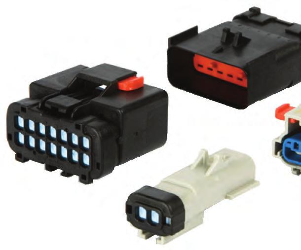
2 APEX Connector Systems: Better By Design The APEX family of electrical connection systems incorporates proven technology for harsh environments in automotive, off-highway, and specialty vehicles. These inline connectors are designed for applications where heat, vibration and moisture are a concern. Superior Design and Construction These pre-assembled connectors minimize stocking inventory and are very easy to assemble and service. There are both sealed and unsealed versions in many configurations from 2-way to 24-way systems, capable of carrying up to 42 amps. The APEX 150 connection systems are the smaller connector, designed for wires sizes from 22 to 16 AWG, and are compatible with USCAR cavity specifications. The APEX 2.8 connection systems offer a wider range of sizes, circuits and options to meet your unique design requirements. A new APEX 24-way Hybrid connection system combines circuits from both the 150 and 2.8 for maximum versatility in a compact package. FCI offers a complete range of innovative and reliable interconnect solutions for Automotive applications. Typical installations include engine compartment, interiors, body harness, safety systems, electronic control units and multimedia. APEX 150 FCI is a global company with approximately 13,000 employees and more than 30 production facilities operating in 30 countries throughout the world and in 15 different languages. TTI Inc. Transportation Business Unit 6480 Rockside Woods Boulevard Suite #110 Independence, OH Phone# (1-877-TTI 4-AUTO) Fax# APEX 2.8 tbu@ttiinc.com


3 Contents


4 APEX APEX Connectors Features and Benefits FEATURE Benefit 1 Polarization molded-in, up to 4 indexes, scoop proof Design flexibility 2 Pre-assembled integral Connector Position Assurance, CPA Ease of assembly 3 Clip slot on male connectors Flexibility for mounting 4 Plastic is molded with smooth well-rounded corners Ergonomics for assembly 5 Double shroud design, protected interface seal Increased durability and handling protection 6 Primary connector lock, audible, tactile, one-hand operation Reliable and easy to mate 7 Pre-assembled integral Terminal Position Assurance, TPA Ease of assembly 8 Blade lead-in / probe protection Durability for service in the field 9 Pre-assembled Rear Mat seal with retainer Ease of assembly Performance Characteristics Temperature Ranges: Class 3: 40 C to +125 C Exceeds USCAR2, 20 Performance Specifications Meets USCAR 21 Crimp Specifications Current Rating: 25 Amps based on USCAR Specification Construction Connector, Mat Seal, Seal Retainer, Interface Seal, TPA and CPA make up the connector assembly Housing Material: PBT 30% GF Interface Seal: Silicone Terminal Compatibility Mat Seal: Silicone 4

5 APEX Terminals Features and Benefits Main Features of APEX terminals Two-piece construction with an integrated floating spring made of beryllium copper Terminal designed to have high current carrying capacity 1. Optimized contact function with: Two stable contact lines One contact point with the spring 2. Fully protected front entry with rounded corners in the four directions: Resistant to probe damage Guides mating blade 3. Protected contact area with a closed box 4. Dimples provide overstress protection of the spring 5. Two symmetrical locking areas: Positive retention achieved in the housing without a vulnerable locking tang Reversibility at Box material is a highly conductive copper alloy for exceptional current rating. 7. Coined edges eliminate the potential to tear the rear mat seal. Non-polarized terminals 5
6 FCI 10 Way APEX 150 Connection System FEMALE MALE INDEX TYPE HOUSING COLOR PLUGGED SEAL POSITIONS (X) FEMALE ASSEMBLY MALE ASSEMBLY (SLOT 1) MALE ASSEMBLY (SLOT 2) A BLACK B GREY C BROWN D GREEN A BLACK X B GREY X A BLACK X X B GREY X X NOTE 1: Assembly part numbers also available without CPA. See sale drawing for part numbers NOTE 2: See Page 9 for explanation of clip slot type 1 and clip slot type 2. Additional plugged cavity configurations are available upon request. 6
7 FCI 14 Way APEX 150 Hybrid Connection System FEMALE MALE HOUSING PLUGGED SEAL POSITIONS (X) FEMALE MALE ASSEMBLY COLOR ASSEMBLY (SLOT 1) A BLACK B GREY C BROWN D GREEN A BLACK X X B GREY X X A BLACK X B GREY X A BLACK X X B GREY X X A BLACK X X X B GREY X X X A BLACK X X X X B GREY X X X X E YELLOW * * F YELLOW * * * * G YELLOW * * H YELLOW * * * * INDEX TYPE NOTE 1: Assembly part numbers also available without CPA. See sale drawing for part numbers NOTE 2: See Page 9 for explanation of clip slot type 1 and clip slot type 2. * Shorting bar exists in this position. Additional plugged cavity configurations are available upon request. MALE ASSEMBLY PART NUMBER (SLOT 2) 7
8 FCI 16 Way APEX 150 Connection System FEMALE MALE INDEX TYPE HOUSING COLOR PLUGGED SEAL POSITIONS (X) FEMALE ASSEMBLY NOTE 1: Assembly part numbers also available without CPA. See sale drawing for part numbers NOTE 2: See Page 9 for explanation of clip slot type 1 and clip slot type 2. Additional plugged cavity configurations are available upon request. MALE ASSEMBLY (SLOT 1) MALE ASSEMBLY (SLOT 2) A BLACK B GREY C BROWN D GREEN A BLACK X B GREY X A BLACK X X B GREY X X A BLACK X X X B GREY X X X A BLACK X X X X B GREY X X X X
 Connection System FEMALE MALE INDEX TYPE HOUSING COLOR FEMALE ASSEMBLY MALE ASSEMBLY A BLACK F934000 F254000 B GRAY F044000 F354000 C BROWN F144000 F454000 D GREEN F244000 F554000 APPLICATION")
9 FCI Sealed 24 Way APEX Hybrid (1.5 mm/2.8 mm) Connection System FEMALE MALE INDEX TYPE HOUSING COLOR FEMALE ASSEMBLY MALE ASSEMBLY A BLACK F F B GRAY F F C BROWN F F D GREEN F F APPLICATION NOTES: APEX 150 CAVITY DESIGNATIONS: CAVITIES 3,4,5,6,7,8,9,10 and 15,16,17,18,19,20,21,22 APEX 2.8 CAVITY DESIGNATIONS: CAVITIES 1,2,11,12,13,14,23,24 ALLOWABLE WIRE SIZE RANGE FOR 1.5 mm CAVITIES: AWG TXL (1.50 mm min. to 2.35 mm max.) ALLOWABLE WIRE SIZE RANGE FOR 2.8 mm CAVITIES: AWG TXL (1.91 mm min. to 3.30 mm max.) ASSOCIATED COMPONENTS: CAVITY PLUG FOR APEX 150 CAVITIES: CAVITY PLUG FOR FEMALE APEX 2.8 CAVITIES: CAVITY PLUG FOR MALE APEX 2.8 CAVITIES: FEATURES CHRYSLER TYPE CLIP SLOT 9

10 APEX Connector Clip Mounting Features (CHRYSLER TYPE) CLIP SELECTION TYPE 1 ONLY DOUBLE X-TREE SUPPLIER: FCI FCI : M5 WELD STUD CLIP FCI :
11 APEX 150 Terminals & Cavity Plug FEMALE MALE FEMALE TERMINAL WIRE GAGE TERMINAL MATERIAL TERMINAL PLATING CuSn Sn CuSn Sn CuTeSn NiPdAu CuTeSn NiPdAu MALE TERMINAL WIRE GAGE TERMINAL MATERIAL TERMINAL PLATING CuSn Sn CuSn Sn CuTeSn NiPdAu CuTeSn NiPdAu MALE TERMINAL for Shorting BAR applications CuTeSn NiPdAu CuTeSn NiPdAu DESCRIPTION APEX 150 Cavity Plug 11

12 APEX 150 Tools Hand Crimp Tool Extraction Tool DESCRIPTION DESCRIPTION Hand Crimp Tool, 22/20 & 18/16 AWG Terminal Extraction Tool Crimp Applicator For Wire Sizes Up To 6 mm 2 QUICK-CRIMP 947 is the crimp applicator for economical processing of stripped crimp terminals. The side feed applicator for left-feed terminals has a mechanical advance. It can be used in semi-automatic bench presses, stripper crimpers or fully automatic wire processing machines. Includes 7 digit cycle counter. Technical Details Wire Cross Section: 0.08 to 6.0 mm 2 Mechanical feed (transversal): Feed Length: 3 to 30 mm Stroke: 40 to 44 mm Shut Height: mm Weight: 4 kg Dimensions: 170 mm wide x 160 mm high x 100 mm deep Options Select crimp height adjustment from self-locking adjustment disks, steps every 0.02 mm Counter 7-digits (not resettable) Ejector between conductor and insulation punch Optional stroke of 30 mm Quick changeover to other terminal with conversion kit 12
13 Terminal Winding Options For Wire Harness Manufacturers STANDARD FCI WINDING IS B. TO ORDER WINDING A USE THE FOLLOWING SUFFIX: 5400xxxxRWA TO ORDER WINDING C USE THE FOLLOWING SUFFIX: 5400xxxxRWC TO ORDER WINDING D USE THE FOLLOWING SUFFIX: 5400xxxxRWD 13
14 APEX 150 Terminal De-Rating Curve APEX 150 Current Derating Discrete Terminals 16 AWG (1.2mm 2 ) Wire 14
 FCI Representative (Male Connector) Customer & Contact Information (Male Connector) Connector Usage Forecast Vehicle Platform Model Year EAU Ramp Volume Begins Model Year EAU Connector")
15 APEX Way Hybrid Custom Configuration Request Form Date of Request FCI Representative (Female Connector) All Fields in RED are Required Date Required by Customer & Contact Information (Female Connector) FCI Representative (Male Connector) Customer & Contact Information (Male Connector) Connector Usage Forecast Vehicle Platform Model Year EAU Ramp Volume Begins Model Year EAU Connector Configuration (Common) A Black Connector Polarization (A, B, C, D, E, F, G, H, J or Doesn't Matter) B Grey C Brown NOTE: Polarizations and Connector Colors are available as shown in chart. D Green Connectors with Shorting Bars are yellow, unless otherwise requested below. E-H Yellow FEMALE Connector Configuration CPA Needed (Yes/No) # Total Blocked Cavities Harness Reference Assigned Circuits (1.5) Assigned Circuits (2.8) Total APEX 2.8mm cavities APEX 2.8mm cavities Cavity numbers as viewed from Rear (wire exits) of Female Connector (See USCAR-12 Appendix A) MALE Connector Configuration Clip Slot (Type 1 or 2) # Total Blocked Cavities Harness Reference Assigned Circuits (1.5) Assigned Circuits (2.8) Total APEX 2.8mm cavities APEX 2.8mm cavities SB1 SB2 SB3 SB SB5 SB6 SB7 SB8 Cavity numbers as viewed from Front of Male Connector (opposite wire exits - See USCAR-12 Appendix A) NOTE: Shorting Bars only short terminals on Male connector when not mated. Any Special Notes or Requests; FCI Engineering Use Only Request Received By Part Numbers Assgned By Date Date FCI Part Number Female Male Customer Part Number Female Male Form: 24 Way Request Form (06SEP2007) 15
16 Apex Way Sealed Custom Configuration Request Form Date of Request FCI Representative (Female Connector) Date Required by Customer & Contact Information (Female Connector) FCI Representative (Male Connector) Customer & Contact Information (Male Connector) Connector Usage Forecast Vehicle Platform Model Year EAU Ramp Volume Begins Model Year EAU Connector Application Connector Configuration (Common) A Black Connector Polarization (A, B, C, D or Doesn't Matter) B Grey C Brown NOTE: Polarizations and Connector Colors are available as shown in chart. D Green FEMALE Connector Configuration CPA Needed (Yes/No) # Blocked Cavities Check if Same Plug Config as Male. Assigned Circuits (1.5) Example: Cavities 2, 8 blocked. 1 2X X 9 10 Cavity numbers as viewed from Rear (wire exits) of of Female Connector (See USCAR-12 Appendix A) MALE Connector Configuration Clip Slot (Type 1 or 2) # Blocked Cavities Check if Same Plug Config as Female Assigned Circuits (1.5) Example: Cavities 2, 8 blocked. 1 2X X 9 10 Cavity numbers as viewed from Front of Male Connector (opposite wire exits - See USCAR-12 Appendix A) Any Special Notes or Requests; Engineering Use Only Request Received By Part Numbers Assgned By Date Date FCI Part Number Female Male Customer Part Number Female Male Form: 10 Way Request Form (06MAR2007) 16
17 Apex Way Sealed Custom Configuration Request Form Date of Request FCI Representative (Female Connector) Date Required by Customer & Contact Information (Female Connector) FCI Representative (Male Connector) Customer & Contact Information (Male Connector) Connector Usage Forecast Vehicle Platform Model Year EAU Ramp Volume Begins Model Year EAU Connector Application Connector Configuration (Common) A Black Connector Polarization (A, B, C, D, E, F, G, H or Doesn't Matter) B Grey C Brown NOTE: Polarizations and Connector Colors are available as shown in chart. D Green Connectors with Shorting Bars are yellow, unless otherwise requested below. E-H Yellow FEMALE Connector Configuration CPA Needed (Yes/No) # Blocked Cavities Check if Same Plug Config as Male. Assigned Circuits (1.5) Assigned Circuits (2.8) Total 2.8mm cavities 2.8mm cavities Harness Reference Cavity numbers as viewed from Rear (wire exits) of of Female Connector (See USCAR-12 Appendix A) Example: Cavities 1, 5 blocked, Circuits 2,3 shorted. 2.8mm cavities 2.8mm cavities SB1 YES SB2 1X X SB3 SB4 MALE Connector Configuration Clip Slot (Type 1 or 2) # Blocked Cavities Check if Same Plug Config as Female Assigned Circuits (1.5) Assigned Circuits (2.8) Total 2.8mm cavities 2.8mm cavities Harness Reference Type 'YES' if/where shorting bars needed. SB1 SB2 Example: Cavities 1, 5 blocked, Circuits 2,3 shorted. 2.8mm cavities SB1 YES SB2 1X X 6 7 SB3 SB SB3 SB4 Cavity numbers as viewed from Front of Male Connector (opposite wire exits - See USCAR-12 Appendix A) NOTE: Shorting Bars only short terminals on Male connector when not mated. Any Special Notes or Requests; 2.8mm cavities Engineering Use Only Request Received By Part Numbers Assgned By Date Date FCI Part Number Female Male Customer Part Number Female Male Form: 14 Way Request Form (06MAR2007) 17
18 Apex Way Sealed Custom Configuration Request Form Date of Request FCI Representative (Female Connector) Date Required by Customer & Contact Information (Female Connector) FCI Representative (Male Connector) Customer & Contact Information (Male Connector) Connector Usage Forecast Vehicle Platform Model Year EAU Ramp Volume Begins Model Year EAU Connector Application Connector Configuration (Common) A Black Connector Polarization (A, B, C, D or Doesn't Matter) B Grey C Brown NOTE: Polarizations and Connector Colors are available as shown in chart. D Green FEMALE Connector Configuration CPA Needed (Yes/No) # Blocked Cavities Check if Same Plug Config as Male. Assigned Circuits (1.5) Cavity numbers as viewed from Rear (wire exits) of of Female Connector (See USCAR-12 Appendix A) 1 9 Example: Cavities 2, 8 blocked. 2X X 16 MALE Connector Configuration Clip Slot (Type 1 or 2) # Blocked Cavities Check if Same Plug Config as Female Assigned Circuits (1.5) Example: Cavities 2, 8 blocked. Cavity numbers as viewed from Front of Male Connector (opposite wire exits - See USCAR-12 Appendix A) 1 9 2X X 16 Any Special Notes or Requests; Engineering Use Only Request Received By Date Part Numbers Assgned By Date FCI Part Number Female Male Customer Part Number Female Male Form: 16 Way Request Form (06MAR2007) 18
19 APEX 150 Hybrid Connector Family (Terminal Replacement) Application Specification K MAY 2009 Rev D 1 Introduction. This document applies to the proper procedure and steps required to manually install and replace APEX 2.8 (2.8mm) and APEX 150 (1.5mm) terminals in the APEX 150 Hybrid Connector Family. When the terminal is correctly installed, there will be a small click and some tactile feedback. 1.1 Reference FCI Terminal Drawings: J54009-CUST APEX 150 Female Terminal J54011-CUST APEX 150 Male Terminal C15004-CUST APEX 2.8 Female Terminal C15005-CUST APEX 2.8 Male Terminal FCI Connector Drawings: K53001 K53002 Required Tools: Small Needle Nose Pliers (Recommended: Sears Craftsman #45664) APEX 150 Service Tool ( ) APEX 2.8 Service Tool ( ) 2 Terminal Insertion Instructions 2.1 Female Terminals Make sure TPA is in the pre-lock position in the female housing. See figure 1. Figure 2 Once all the terminals are inserted in the correct position, then press the TPA into the final lock position as shown in figure 1. If the TPA will not move into the final-lock position, verify that all terminals are fully seated. 2.2 Male Terminals Make sure TPA is in the pre-lock position in the female housing. See figures 5 and 6. Orient the male terminals correctly with each terminal position opening in the male connector assembly as shown in Figure 3. Pre-Lock Final-Lock Figure 1 Orient the female terminals correctly with each terminal position opening in the retainer of female connector assembly as shown in figure 2. Carefully insert the terminal into the cavity opening. Only slight force should be needed. If the force to install each terminal seems high or the terminal will not seat Stop! Remove the terminal, recheck its orientation, verify the cavity does not have a seal plug, and verify the TPA is fully in the pre-lock position. Figure 3 Carefully insert the terminal into the cavity opening. If the force to install each terminal seems high or the terminal will not seat Stop! Remove the terminal, recheck its orientation, verify the cavity FCI FCI USA, USA, Novi, Inc. Michigan. Novi, All Michigan. rights reserved. All rights APEX reserved. is a registered APEX Trademark is a registered of FCI. This Trademark controlled document of FCI. is subject to change. This controlled document is subject to change. For latest revision, sample orders, service tools and hand crimpers, visit or call FCISMPL ( ) 19 1 of 3 Rev D
20 APEX 150 Hybrid Connector Family (Terminal Replacement) Application Specification K MAY 2009 Rev D does not have a seal plug and verify the TPA is fully in the pre-lock position (Figure 4). When the terminal is correctly installed, there will be a small click and some tactile feedback. Once all the terminals are inserted in the correct position, then press the TPA into the final lock position as shown in figure 5. If the TPA will not move into the final-lock position, verify that all terminals are fully seated. equipped. Tabs may be damaged leading to a failure of the shorting bar function. Pre-Lock Figure 4 Figure 6 With the TPA in the pre-lock position, insert the tip of the Service Tool into the service port of the terminal in be removed/replaced. (Figure 7). NOTE: Care should be used so as to not insert the service tool into the terminal opening. Push The Service Tool until resistance is felt. Carefully press harder until the service tool moves slightly further into the connector (this may be accompanied by a small tactile sensation). At this point the selected terminal is ready to be removed. Final-Lock 3 Terminal Replacement Instruction 3.1 Female Connector Figure 5 Insert a small flat blade screw driver in the slot provided in the TPA and apply pressure to Bridge area of connector as shown in figure 6. Gently pry or pivot the screw driver thus sliding the TPA into the Pre-Lock position. WARNING: Do not grab or grip the Shorting Bar tabs if so Service Ports Figure 7 While maintaining pressure on the service tool, the selected terminal may be removed from the rear of the connector by pulling it out by the wire. To help maintain seal integrity, if possible, pull the wire at a small angle away from the connector center as shown in Fig 8 (Not required for 2.8mm terminals). NOTE: Terminal removal should require only a gentle pulling force applied to the wire. If the terminal stays retained or seems stuck, try reinserting the service tool FCI FCI USA, USA, Novi, Inc. Michigan. Novi, All Michigan. rights reserved. All rights APEX reserved. is a registered APEX Trademark is a registered of FCI. This Trademark controlled document of FCI. is subject to change. This controlled document is subject to change. For latest revision, sample orders, service tools and hand crimpers, visit or call FCISMPL ( ) 20 2 of 3 Rev D
21 APEX 150 Hybrid Connector Family (Terminal Replacement) Application Specification K MAY 2009 Rev D To attach a new terminal to the wire see the appropriate APEX Terminal Crimping Guide. 3.1 Male Connector Figure 8 Figure 9 Push The Service Tool until resistance is felt. Gently press harder until the service tool moves slightly further into the connector (this may be accompanied by a small tactile sensation). Service Port Grip the TPA with a pair of serrated needle nose pliers by using the appropriate holes in the center of the TPA (Figure 9). Gently pull the TPA into the Pre-Lock position. The TPA should not be removed from the connector. WARNING: Care must be used so the pliers do not slip out of the service holes and damage any exposed terminal blades or pinch the operators hands. With the TPA in the pre-lock position, insert the tip of the Service Tool into the service port for the terminal in be removed/replaced. Use care to be sure the service tool stays in the service port track. (Fig 10). Figure 10 While maintaining pressure on the service tool, the selected terminal may be removed from the rear of the connector by simply pulling it out by its wire. NOTE: Terminal removal should require only a gentle pulling force applied to the wire. If the terminal stays retained or seems stuck, try reinserting the service tool FCI FCI USA, USA, Novi, Inc. Michigan. Novi, All Michigan. rights reserved. All rights APEX reserved. is a registered APEX Trademark is a registered of FCI. This Trademark controlled document of FCI. is subject to change. This controlled document is subject to change. For latest revision, sample orders, service tools and hand crimpers, visit or call FCISMPL ( ) 21 3 of 3 Rev D
22 APEX 150 ErgoMate Connector Family Application Specification K FEB 2008 Rev B 1 Introduction This document applies to the proper procedures and steps required to manually install and replace APEX 2.8 (2.8mm) and APEX 150 (1.5mm) terminals in the APEX 150 ErgoMate Connector Family. Also, general application suggestions are covered. 2 Terminal Insertion Instructions 2.1 Female Terminals Make sure TPA is in the pre-lock position in the female housing. See Figure 2.1a. 1.1 Reference FCI Terminal Drawings: J54009-CUST APEX 150 Female Terminal J54011-CUST APEX 150 Male Terminal C15004-CUST APEX 2.8 Female Terminal C15005-CUST APEX 2.8 Male Terminal FCI Connector Drawings: PCC ErgoMate 24 Way Female PCC ErgoMate 24 Way Male PCC ErgoMate 24 Way Female for MVM PCC ErgoMate 24 Way Male for MVM Pre-Lock Figure 2.1a Recommended Tools: Small Needle Nose Pliers (Sears Craftsman #45664) APEX 150 Service Tool ( ) APEX 2.8 Service Tool (5400EXT) 1.2 Terminology Slider CPA Final-Lock Figure 2.1b Orient the female terminals correctly with each terminal position opening in the retainer of female connector assembly as shown in figure 2.1c. The APEX 2.8 terminals can TPA Female Slider Lock Release TPA Male Clip-Slot Feature Figure 2.1c Carefully insert the terminal into the cavity opening. Only slight force should be needed. If the force to install each terminal seems high or the terminal will not seat Stop! Remove the terminal, recheck its orientation, verify the FCI FCI USA, USA, Novi, Inc. Michigan. Novi, All Michigan. rights reserved. All rights APEX reserved. is a registered APEX Trademark is a registered of FCI. This Trademark controlled document of FCI. is subject to change. This controlled document is subject to change. For latest revision, sample orders, service tools and hand crimpers, visit or call FCISMPL ( ) 22 1 of 4 Rev B
23 APEX 150 ErgoMate Connector Family Application Specification K FEB 2008 Rev B cavity does not have a seal plug, and verify the TPA is fully in the pre-lock position. When the terminal is correctly installed, there will be a small click and some tactile feedback. Once all the terminals are inserted in the correct position, then press the TPA into the final lock position as shown in figure 2.1b. If the TPA will not move into the final-lock position, verify that all terminals are fully seated. 2.2 Male Terminals Make sure TPA is in the pre-lock position in the female housing. See figure 2.2a. a seal plug and verify the TPA is fully in the pre-lock position (Figure 2.2a). When the terminal is correctly installed, there will be a small click and some tactile feedback. Once all the terminals are inserted in the correct position, then press the TPA into the final lock position as shown in figure 2.2b. If the TPA will not move into the final-lock position, verify that all terminals are fully seated. 3 Mating and Un-mating the ErgoMate System 3.1 Un-mating Slide the CPA (if so equipped) from the Locked position to the Un-Locked position. Doing so unlocks the Gear/Cam so the system can be disconnected. Pre-Lock Figure 2.2a CPA Locked CPA Un-Locked Figure 3.1a Final-Lock Figure 2.2b Orient the male terminals correctly with each terminal position opening in the male connector assembly as shown in Figure 2.2c. Squeeze the Slider lock release in the location shown & then pull the slider axially in the direction shown. (See figure 3.1b). Figure 3.1b Figure 2.2c Carefully insert the terminal into the cavity opening. If the force to install each terminal seems high or the terminal will not seat Stop! Remove the terminal, recheck its orientation (Figure 2.2c), verify the cavity does not have FCI FCI USA, USA, Novi, Inc. Michigan. Novi, All Michigan. rights reserved. All rights APEX reserved. is a registered APEX Trademark is a registered of FCI. This Trademark controlled document of FCI. is subject to change. This controlled document is subject to change. For latest revision, sample orders, service tools and hand crimpers, visit or call FCISMPL ( ) 23 2 of 4 Rev B
24 APEX 150 ErgoMate Connector Family Application Specification K FEB 2008 Rev B 3.2 Mating Grip the Female Connector by the slider. Engage the male and female connector halves in the proper orientation by sliding the female connector onto the male side. When adequate engagement is achieved, the slider will release from the female connector and begin to slide along the system. (See Figure 3.2a) Figure 4.1b Figure 3.2a When the connectors are fully engaged, the CPA can be pushed into the Locked position. (See Figure 3.1a) The connector system is now fully mated. 4 Servicing and Replacing Terminals With the TPA in the pre-lock position, insert the tip of the Service Tool into the service port of the terminal to be removed/replaced. (Figure 4.1c). NOTE: Care should be used so as to not insert the service tool into the terminal opening. Service Ports 1.5mm 4.1 Female Connector Gently pull the TPA into Pre-Lock position by gripping the TPA as shown in figure 4.1a. To avoid damaging the TPA, use care to not pull the TPA out of the connector! 2.8mm Figure 3.2a Terminal Openings Figure 4.1a WARNING: Do not grab or grip the Shorting Bar tabs if so equipped (see Figure 4.1b). Tabs may be damaged leading to a failure of the shorting bar function. Push The Service Tool until resistance is felt. Carefully press harder until the service tool moves slightly further into the connector (this may be accompanied by a small tactile sensation). At this point the selected terminal is ready to be removed. While maintaining pressure on the service tool, the selected terminal may be removed from the rear of the connector by pulling it out by the wire. To help maintain seal integrity, if possible, pull the wire at a small angle away from the connector center as shown in Figure 4.1d (Not required for 2.8mm terminals). NOTE: Terminal removal should require only a gentle pulling force applied to the wire. If the terminal stays retained or seems stuck, try reinserting the service tool FCI FCI USA, USA, Novi, Inc. Michigan. Novi, All Michigan. rights reserved. All rights APEX reserved. is a registered APEX Trademark is a registered of FCI. This Trademark controlled document of FCI. is subject to change. This controlled document is subject to change. For latest revision, sample orders, service tools and hand crimpers, visit or call FCISMPL ( ) 24 3 of 4 Rev B
25 APEX 150 ErgoMate Connector Family Application Specification K FEB 2008 Rev B While maintaining pressure on the service tool, the selected terminal may be removed from the rear of the connector by simply pulling it out by its wire. NOTE: Terminal removal should require only a gentle pulling force applied to the wire. If the terminal stays retained or seems stuck, try reinserting the service tool. Figure 4.1d To attach a new terminal to the wire see the appropriate APEX Terminal Crimping Guide. 4.2 Male Connector Grip the TPA with a pair of serrated needle nose pliers by using the center of the rib on the TPA (Figure 4.2a). Figure 4.2a Gently pull the TPA into the Pre-Lock position. The TPA should not be removed from the connector. WARNING: Care must be used so the pliers do not slip off of the rib and damage any exposed terminal blades or pinch the operator s hands. NOTE: Do NOT remove the male TPA from the connector! Doing so may cause permanent damage to the TPA and make replacement effort difficult. With the TPA in the pre-lock position, insert the tip of the Service Tool into the service port for the terminal in be removed/replaced. (Fig 4.2b). 5 Application Guide 5.1 Clearances When designing applications and harnesses that utilize ErgoMate connectors, care must be use to assure that there is sufficient clearance around the connector to access the CPA and mate and un-mate the connector as described in section Special Applications Female Clip-Slot: The ErgoMate system may be configured with a clip-slot on the female slider in combination with no clip-slot on the male connector. In this configuration, the slider will be fixed and the internal body of the female connector will slide backward (at least 23mm) during the mating process. It will be necessary to dress the wire bundle to the left or the right to assure low mate forces (see example in figure 5.2) and to be sure there is sufficient clearance behind the female connector wire bundle to assure proper mating. In this configuration, single handed mating is possible by simply pushing the male connector into the female connector, however, two hands will be required to unmate the connector in this case, one to release the female slider lock, and another to pull out the male connector. Terminal Opening Figure 5.2 Service Port Figure 4.2b Push The Service Tool until resistance is felt. Gently press harder until the service tool moves slightly further into the connector (this may be accompanied by a small tactile sensation). 5.3 Connector Orientation As is true with any sealed connector system used in a wet environment, the in service orientation of the connector should have the mating axis of the connector in as horizontal an orientation as possible. This prevents water from pooling in the wire openings FCI FCI USA, USA, Novi, Inc. Michigan. Novi, All Michigan. rights reserved. All rights APEX reserved. is a registered APEX Trademark is a registered of FCI. This Trademark controlled document of FCI. is subject to change. This controlled document is subject to change. For latest revision, sample orders, service tools and hand crimpers, visit or call FCISMPL ( ) 25 4 of 4 Rev B
, scoop proof Design flexibility 2 Pre-assembled integral Connector Position Assurance,")
26 APEX 2.8 mm Connectors Features and Benefits FEATURE Benefit 1 Polarization molded-in, up to 4 indexes (7 on 10-ways), scoop proof Design flexibility 2 Pre-assembled integral Connector Position Assurance, CPA Ease of assembly 3 Clip slot on all male and 2-, 10- and 14-way female connectors Flexibility for mounting 4 Plastic is molded with smooth well-rounded corners Ergonomics for assembly 5 Double shroud design, protected interface seal Increased durability 6 Primary connector lock, audible, tactile, one-hand operation Reliable and easy to mate 7 Pre-assembled integral Terminal Position Assurance, TPA Ease of assembly 8 Blade lead-in/probe protection Durability for service in the field 9 Molded-in locking finger Audible seat and ease of service 10 Pre-assembled Rear Mat seal with retainer Ease of assembly 11 Available in 2, 3, 4, 5, 6, 10 and 14 cavity configurations sealed and unsealed Design flexibility 12 Sealed and Unsealed housings use the same connectors and terminals Terminal standardization 13 Fewer part number to manage in OEM database Reduce engineering costs 14 Optional material for Class 4 ( 40 C to +150 C) applications Extreme temperatures 15 No special tools required to service the connector & terminal Ease of service Performance Characteristics Temperature Ranges: Class 3: 40 C to +125 C Class 4: 40 C to +150 C Exceeds USCAR-2 Performance Specification Validated for Diesel Engines Applications Construction Connector, Mat Seal, Seal Retainer, Interface Seal, TPA and CPA make up the connector assembly Housing Material: Nylon 35% GF Interface Seal: Silicone Mat Seal: Silicone Terminal Compatibility APEX 2.8: Tin or Gold Plated 26
27 FCI 2-Way APEX 2.8 mm Connection System FEMALE MALE Sealed Assembly Unsealed Assembly Sealed Assembly Unsealed Assembly INDEX TYPE HOUSING COLOR SEALED/ UNSEALED FEMALE ASSEMBLY MALE ASSEMBLY TEMPERATURE RATING OF MATERIAL WIRE INSULATION RANGE PER CAVITY (mm) A DK GRN SEALED C to +150 C B DK BLUE SEALED C to +150 C C DK BROWN SEALED C to +150 C D TAN SEALED C to +150 C A BLK SEALED C to +125 C A BLK SEALED C to +125 C A BLK UNSEALED C to +125 C B LT GREY SEALED C to +125 C B LT GREY UNSEALED C to +125 C C DK GREY SEALED C to +125 C D NATURAL SEALED C to +125 C Note: Additional configurations available. Please consult sales drawing. Female part numbers with the N suffix are without CPA latch. 27
28 FCI 3-Way APEX 2.8 mm Connection System FEMALE MALE Sealed Assembly Unsealed Assembly Sealed Assembly Unsealed Assembly INDEX TYPE HOUSING COLOR SEALED/ UNSEALED FEMALE ASSEMBLY MALE ASSEMBLY TEMPERATURE RATING OF MATERIAL WIRE INSULATION RANGE PER CAVITY (mm) A DK GRN SEALED C to +150 C A BLK SEALED C to +125 C A BLK UNSEALED C to +125 C B LT GREY SEALED C to +125 C B LT GREY UNSEALED C to +125 C C DK GREY SEALED C to +125 C D NATURAL SEALED C to +125 C D NATURAL UNSEALED C to +125 C C DK GREY UNSEALED C to +125 C A BLACK SEALED N* SEAL W/O HOLES USED AS CAP A BLACK SEALED * SEAL W/O HOLES USED AS CAP * Plug for same index (A) mating part. Note: Female part numbers with the N suffix are without CPA latch. 3.35mm wire diameter sealing is available in select configurations. Consult sales drawing. Additional configurations available. Please consult sales drawing. 28
29 FCI 4-Way APEX 2.8 mm Connection System FEMALE MALE Sealed Assembly Unsealed Assembly Sealed Assembly Unsealed Assembly INDEX TYPE HOUSING COLOR SEALED/ UNSEALED FEMALE ASSEMBLY MALE ASSEMBLY TEMPERATURE RATING OF MATERIAL WIRE INSULATION RANGE PER CAVITY (mm) A BLK SEALED C to +125 C A BLK UNSEALED C to +125 C B LT GREY SEALED C to +125 C C DK GREY SEALED C to +125 C C DK GREY UNSEALED C to +125 C D NATURAL SEALED C to +125 C D NATURAL UNSEALED C to +125 C B LT GREY SEALED * SEAL W/O HOLES USED AS CAP A BLACK SEALED * SEAL W/O HOLES USED AS CAP * Plug for same index (A) mating part. Note: Female part numbers with the N suffix are without CPA latch. 3.35mm wire diameter sealing is available in select configurations. Consult sales drawing. Additional configurations available. Please consult sales drawing. 29
30 FCI 5-Way APEX 2.8 mm Connection System FEMALE DIRECT CONNECT INTERFACE Sealed Assembly Unsealed Assembly INDEX TYPE HOUSING COLOR SEALED/ UNSEALED FEMALE ASSEMBLY MALE ASSEMBLY TEMPERATURE RATING OF MATERIAL WIRE INSULATION RANGE PER CAVITY (mm) A BLK UNSEALED DIRECT CONNECT 40 C to +125 C B LT GREY UNSEALED DIRECT CONNECT 40 C to +125 C C DK GREY UNSEALED DIRECT CONNECT 40 C to +125 C D NATURAL UNSEALED DIRECT CONNECT 40 C to +125 C A BLK SEALED DIRECT CONNECT 40 C to +125 C B LT GREY SEALED DIRECT CONNECT 40 C to +125 C C DK GREY SEALED DIRECT CONNECT 40 C to +125 C D NATURAL SEALED DIRECT CONNECT 40 C to +125 C Note: Female part numbers with the N suffix are without CPA latch. 30
31 FCI 6-Way APEX 2.8 mm Connection System FEMALE MALE Sealed Assembly Unsealed Assembly Sealed Assembly Unsealed Assembly INDEX TYPE HOUSING COLOR SEALED/ UNSEALED FEMALE ASSEMBLY MALE ASSEMBLY TEMPERATURE RATING OF MATERIAL WIRE INSULATION RANGE PER CAVITY (mm) A BLK SEALED C to +125 C A BLK UNSEALED C to +125 C B LT GREY SEALED C to +125 C B LT GREY UNSEALED C to +125 C C DK GREY SEALED C to +125 C C DK GREY UNSEALED C to +125 C D NATURAL SEALED C to +125 C D NATURAL UNSEALED C to +125 C A BLACK SEALED * SEAL W/O HOLES USED AS CAP A BLACK SEALED * SEAL W/O HOLES USED AS CAP * Plug for same index (A) mating part. Note: Female part numbers with the N suffix are without CPA latch. 3.35mm wire diameter sealing is available in select configurations. Consult sales drawing. Additional configurations available. Please consult sales drawing. 31

32 FCI 10-Way APEX 2.8 mm Connection System FEMALE MALE Sealed Assembly Unsealed Assembly Sealed Assembly Unsealed Assembly INDEX TYPE HOUSING COLOR SEALED/ UNSEALED FEMALE ASSEMBLY MALE ASSEMBLY TEMPERATURE RATING OF MATERIAL WIRE INSULATION RANGE PER CAVITY (mm) A BLK SEALED C to +125 C A BLK UNSEALED C to +125 C B LT GREY SEALED C to +125 C C LT GRN SEALED C to +125 C C LT GRN UNSEALED C to +125 C G LT BRN SEALED C to +125 C A BLACK SEALED N* SEAL W/O HOLES USED AS CAP A BLACK SEALED * SEAL W/O HOLES USED AS CAP B LT GREY SEALED * SEAL W/ O HOLES USED AS CAP B LT GREY UNSEALED C to +125 C C LT GRN SEALED * SEAL W/ O HOLES USED AS CAP * Plug for same index (A, B or C) mating connector. Note: Female part numbers with the N suffix are without CPA latch. Additional configurations available. Please consult sales drawing. 32

33 FCI 14-Way APEX 2.8 mm Connection System FEMALE MALE Sealed Assembly Unsealed Assembly Sealed Assembly Unsealed Assembly INDEX TYPE HOUSING COLOR SEALED/ UNSEALED FEMALE ASSEMBLY MALE ASSEMBLY TEMPERATURE RATING OF MATERIAL WIRE INSULATION RANGE PER CAVITY (mm) A BLACK SEALED C to +125 C A BLACK UNSEALED C to +125 C B LT GREY SEALED C to +125 C B LT GREY UNSEALED C to +125 C C DK GRAY SEALED C to +125 C D TAN SEALED C to +125 C A BLACK SEALED N SEAL W/NO HOLES USED AS CAP* A BLACK SEALED SEAL W/NO HOLES USED AS CAP* B LT GREY SEALED SEAL W/NO HOLES USED AS CAP* B DK GREY SEALED SEAL W/NO HOLES USED AS CAP* C NATURAL SEALED SEAL W/NO HOLES USED AS CAP* Note: Female part numbers with the N suffix are without CPA latch. *Cap for corresponding connector index type. 33
34 FCI 14-Way APEX 2.8 Power Shunt Unsealed (14-Way Shunt) (12-Way Shunt 2x6 bus bars) INDEX TYPE HOUSING COLOR SEALED/ UNSEALED Power Shunt B LT GREY UNSEALED B LT GREY UNSEALED MATING FEMALE ASSEMBLY w/clip slot w/finger grip and w/o clip slot TEMPERATURE RATING OF MATERIAL WIRE INSULATION RANGE PER CAVITY (mm) 40 C to +125 C C to +125 C
35 Flanged 6-Way Male APEX 2.8 Connector Part No (Pass-Through Connection) INDEX TYPE HOUSING COLOR SEALED/ UNSEALED MATING FEMALE ASSEMBLY TEMPERATURE RATING OF MATERIAL WIRE INSULATION RANGE PER CAVITY (mm) A BLACK SEALED C to +125 C Note: Additional sealing configuration available to accommodate larger (3.35mm) wire. 35
 INDEX TYPE HOUSING COLOR SEALED/ UNSEALED MATING")
 A BLACK SEALED 54200409 40 C to +125 C 1.70 2.")
36 PCB 14+4 APEX 2.8 Header Connector Part No (PCB Header) INDEX TYPE HOUSING COLOR SEALED/ UNSEALED MATING FEMALE ASSEMBLY TEMPERATURE RATING OF MATERIAL WIRE INSULATION RANGE PER CAVITY (mm) A BLACK SEALED C to +125 C A BLACK SEALED C to +125 C
37 APEX 2.8 mm Terminals & Cavity Plug FEMALE MALE FEMALE TERMINAL WIRE GAGE TERMINAL MATERIAL TERMINAL PLATING CuTeSn/CuBe Sn CuTeSn/CuBe Sn CuTeSn/CuBe Sn CuTeSn/CuBe Sn CuTeSn/CuBe NiPdAu CuTeSn/CuBe NiPdAu CuTeSn/CuBe NiPdAu CuTeSn/CuBe NiPdAu Note: The Nickel/Palladium/Gold plating is recommended for diesel engine applications. Nyogel 8917 low friction insertion grease available on female terminal. NYE 7606 grease available on female terminal for dry circuit applications. MALE TERMINAL WIRE GAGE TERMINAL MATERIAL APEX 2.8 mm Cavity Plug TERMINAL PLATING CuTeSn Sn CuTeSn Sn CuTeSn Sn CuTeSn Sn CuTeSn NiPdAu CuTeSn NiPdAu CuTeSn NiPdAu CuTeSn NiAu CuTeSn NiAu Part No Note: Locks on seal retainers. 37
38 APEX 2.8 mm Connector Clips Double X-Tree Part No Fits both male & female Chrysler type connector clip slot. Double X-Tree Part No Fits male side only Chrysler type connector clip slot. Provides <200N push through retention. Single X-Tree Clip Part No Fits both male & female Chrysler type connector clip slot. M5 Weld Stud Clip Part No Fits both male & female Chrysler type connector clip slot. 38

39 APEX 2.8 mm Tools Hand Crimp Tool Extraction Tool DESCRIPTION APEX2.8MM18/20 Hand Crimp Tool for AWG APEX 2.8 mm Terminals APEX2.8MM14/16 Hand Crimp Tool for AWG APEX 2.8 mm Terminals APEX2.8MM10/12 Hand Crimp Tool for AWG APEX 2.8 mm Terminals 5400EXT DESCRIPTION Terminal Extraction Tool - APEX 2.8 mm Crimp Applicator For Wire Sizes Up To 6 mm 2 QUICK-CRIMP 947 is the crimp applicator for economical processing of stripped crimp terminals. The side feed applicator for left-feed terminals has a mechanical advance. It can be used in semi-automatic bench presses, stripper crimpers or fully automatic wire processing machines. Includes 7 digit cycle counter. Technical Details Wire Cross Section: 0.08 to 6.0 mm 2 Mechanical feed (transversal): Feed Length: 3 to 30 mm Stroke: 40 to 44 mm Shut Height: mm Weight: 4 kg Dimensions: 170 mm wide x 160 mm high x 100 mm deep Options Select crimp height adjustment from self-locking adjustment disks, steps every 0.02 mm Counter 7-digits (not resettable) Ejector between conductor and insulation punch Optional stroke of 30 mm Quick changeover to other terminal with conversion kit 39
40 Terminal Winding Options For Wire Harness Manufacturers STANDARD FCI WINDING IS B. TO ORDER WINDING A USE THE FOLLOWING SUFFIX: 5400xxxxRWA TO ORDER WINDING C USE THE FOLLOWING SUFFIX: 5400xxxxRWC TO ORDER WINDING D USE THE FOLLOWING SUFFIX: 5400xxxxRWD 40
41 APEX 2.8 mm Terminal De-Rating Curves FCI AUTO PART NO. GROUP FEMALE MALE WIRE TYPE 14 Gage ga. TXL 18 Gage ga. TXL 2.5 mm mm FLRY - B 1.5 mm mm FLRY - B 1.0 mm mm FLRY - B 0.75 mm mm FLRY - B 0.50 mm mm FLRY - B 0.35 mm mm FLRY - B 41
42 APEX 2.8 mm Connector Assembly Instructions FEMALE 1 CPA and TPA in pre-staged position MALE 1 CPA and TPA in pre-staged position CPA TPA TPA 2 Insert male terminal through rear mat seal. The grip may be oriented either up or down. 2 Insert male terminal through rear mat seal. The grip may be oriented either up or down. 3 Seat male terminal into connector cavity. Listen for audible click. 3 Seat male terminal into connector cavity. Listen for audible click. 4 Push TPA into its locked position. 4 Push TPA into its locked position. 42
43 APEX 2.8 mm Terminal Extraction Instructions FEMALE 1 Remove TPA from connector. Pull from slotted post/rib. MALE 1 Remove TPA from connector. Pull from post. TPA TPA 2 Use extraction tool to remove the terminals after removal of TPA. 2 Use extraction tool to remove the terminals after removal of TPA. Flat Tip 3 Slightly lift plastic finger lock in the cavity while pulling on the wire to remove the terminals out of the rear of the connection housing. 3 Slightly lift plastic finger lock in the cavity while pulling on the wire to remove the terminals out of the rear of the connection housing. 43
44 TTI Inc. Transportation Business Unit 6480 Rockside Woods Boulevard Suite #110 Independence, OH Phone# Fax# FSC LOGO 11M tall CM5K 05/09
Stac64 Unsealed Connector System
 Stac64 Unsealed Connector System Applications To address the growing electronic device requirements within today s vehicles, Molex has developed a modular 0.64, 1.50 and 2.80mm (.025,.059 and.110") terminal
APEX Product Line Overview. March 2008 V3
 APEX Product Line Overview March 2008 V3 Welcome to APEX Thank you for your interest in APEX. You are about to learn about one of the best connection systems available anywhere in the world. APEX is a
PNI Connectors. 2.0mm pitch wire to board/wire to wire solutions. Purpose:
 PNI Connectors 2.0mm pitch wire to board/wire to wire solutions Purpose: To introduce the PNI wire-to-board and wire-to-wire, crimp style connector from JST. Objectives: Illustrate the intended application.
Stac64 Connection System Unsealed Headers and Receptacles
 Modular, stackable connection system offers single- and multi-bay header solutions to maximize design flexibility in unsealed Transportation applications and greatly reduces time-to-market by eliminating
CMC Hybrid Connectors Standard and Power Versions
 The Molex family of provides a sealed, high-density, modular and cost-effective connection system for heavy-duty, powertrain and body-electronics applications in the transportation industry The CMC connector
Stac64 Unsealed Connector System
 Unsealed Connector System pplications To address the growing electronic device requirements within today s vehicles, Molex has developed a modular 0.64, 1.50 and 2.80mm (.025,.059 and.110") terminal header
CMC CP Terminals CP 0.635mm (.025 ) CP 1.50mm (.059 ) CP 2.80mm (.110 ) FEATURES AND SPECIFICATIONS
 CP 1.50mm (.059 ) CP 2.80mm (.110 ) FEATURES AND SPECIFICATIONS") FEATURES AND SPECIFICATIONS CMC Connectors sealed, high-density, modular and cost-effective connection system for heavy-duty applications The CMC connector family from Molex is a sealed, high-density connection
FEATURES AND SPECIFICATIONS CMC Connectors sealed, high-density, modular and cost-effective connection system for heavy-duty applications The CMC connector family from Molex is a sealed, high-density connection
Connector System for Circular Contacts
 Connector System for Circular Contacts Introduction The diameter 1.5 mm and diameter 2.5 mm Connector System is designed for electronic and electrical applications in motor vehicles. It fullfils all requirements
Datasheet for
 80 Morgan Street Rockford, Illinois 60 800-435-93 Datasheet for 76650-05 General Information Part Number: 76650-05 Manufacturer: Molex / Waldom Title: Deluxe Splashproof Application Kit Includes USB Type
ASSEMBLY INSTRUCTIONS for 16 WAY GT MIXED 150/280 SEALED CONNECTION SYSTEM
 ASSEMBLY INSTRUCTIONS for 16 WAY GT MIXED 150/280 SEALED CONNECTION SYSTEM NOTE: PLEASE CONTACT YOUR DELPHI SALES REPRESENTATIVE WITH ANY QUESTIONS OR COMMENTS CONCERNING THESE ASSEMBLY INSTRUCTIONS. COMPONENT
AMP Drawer Series Connectors Miniature Power Drawer (MPD) Connectors
 Connectors") Miniature Power Drawer (MPD) Connectors Product Facts High mating cycle life Low Mating and Un-mating force (< 0.2lbs per contact) Single-piece molded housing Molded-in guide pins provide generous blind-mateability
Miniature Power Drawer (MPD) Connectors Product Facts High mating cycle life Low Mating and Un-mating force (< 0.2lbs per contact) Single-piece molded housing Molded-in guide pins provide generous blind-mateability
(Smallest Circuit) Current Rating. (Largest Circuit) Housing Lock. Current Rating. 12A 11A Positive or None
 Current Rating. (Largest Circuit) Housing Lock. Current Rating. 12A 11A Positive or None") General Overview The Jr. was specifically developed for positive locking, wire-to-wire and wire-to-board applications. It is available in single row and dual row versions. The system offers the widest
General Overview The Jr. was specifically developed for positive locking, wire-to-wire and wire-to-board applications. It is available in single row and dual row versions. The system offers the widest
Positive Mate Connection System
 Introduction High Current Flow with Low Insertion Force Product Features All Positive Mate housings include a secondary contact retention feature Polarization is provided Rounded corners on housings prevent
SUPPLEMENT TO YESC CATALOG
 SUPPLEMENT TO YESC CATALOG YESC KAIZEN stands for continuous improvement the heart of a tradition that s helped make Yazaki the world s largest supplier of vehicle power and data networks, and related
AMPMODU* MOD I Interconnection System
 Product Specification AMPMODU* MOD I Interconnection System 03 JUN 2013 Rev E All Paragraphs Revised 1. SCOPE This specification covers performance and test requirements for the AMPMODU MOD I Interconnection
2 PIECE BOARD-TO-BOARD
 2 PIECE BOARD-TO-BOARD 201-01-123 1. SPECIFICATION DISTRIBUTION No restrictions for issue 2. SCOPE This specification contains the application notes for the 9159 two part connectors. 3. PRODUCTS 10-9159
VMEbus systems System description Technical characteristics System description
 Directory chapter 06 / inverse Page VMEbus systems................................................ 06.02 System description.............................................. 06.03 Technical characteristics..........................................
SSL - Top Load Socket
 The 9159 series of Board-to-Board interconnect system allows two PCB's to be mated end-to-end creating strips of LED lighting. Designed specifically for the unique Solid State Lighting (SSL) market requiring
ATM SERIES ATM Series
 SERIES Series CONNECTOR SOLUTIONS 21 Series Overview Series connectors are a high-performance, cost-effective solution specifically designed for smaller AWG applications, while still maintaining the strengths
ATP SERIES ATP Series
 ATP SERIES ATP Series 87 ATP Series Overview ATP Series connectors are designed as a high-performance, cost-effective, thermoplastic solution to be used within the Marine, Heavy Equipment, Agricultural,
FLAT FLEXIBLE CABLE (FFC) CONNECTORS
 CONNECTORS") FLAT FLEXIBLE CABLE (FFC) CONNECTORS TE Connectivity s (TE) family of FFC connectors includes a variety of high density cable-to-board and cable-to-cable connectors designed for automated assembly. The
FLAT FLEXIBLE CABLE (FFC) CONNECTORS TE Connectivity s (TE) family of FFC connectors includes a variety of high density cable-to-board and cable-to-cable connectors designed for automated assembly. The
APPLICATION SPECIFICATION
 MOLEX MINI 50 0.50MM CONNECTOR SYSTEM PPLICTION SPECIFICTION 1.0 SCOPE THIS PROCEDURE PPLIES TO LL PRT NUMBERS IN THE 34791, 34792, ND 34793 SERIES Table of Contents 1: Product Scope 2: Product Description
STANDARD FOR ELECTRICAL CONTACTS, RETENTION CRITERIA
 INCH-POUND MSFC-STD-781 National Aeronautics and REVISION A Space Administration EFFECTIVE DATE: August 1, 2007 George C. Marshall Space Flight Center Marshall Space Flight Center, Alabama 35812 MULTIPROGRAM/PROJECT
NG POWER TERMINALS AND CONNECTORS
 NG POWER TERMINALS AND CONNECTORS for the Automotive Industry FOR THE AUTOMOTIVE INDUSTRY INNOVATIVE TECHNOLOGIES TE Connectivity (TE) is a leader in automotive connectivity and sensor technology. Our
MTA-156 IDC Quad Connectors
 MT-156 IDC Quad Connectors MT-156 Product Facts Provides four points of contact Greater current carrying capability than Standard MT-156 Connectors Connector styles include both closed end and feedthru
07. har-link INTERFACE CONNECTORS
 . INTERFACE CONNECTORS The highest data rates in combination with perfect shielding characterize the connector. This way data can be passed on optimally within the control cabinet. The locking mechanism
EXTreme Guardian Power Connector System
 Exceed high-current and reliability requirements in topend server and high-power applications with Molex s compact,, providing EMI/RFI shielding, overmolding and discretewire options for design flexibility
Environmentally Sealed
 Weather-Pack 16 Metri-Pack 19 AMP Superseal 24 Ampseal 16 27 M12 Network 30 DIN Connectors 31 Schlemmer / Din Conduit Sealed 32 Schlemmer / Din Contact Sealed 34 Ideal for applications requiring protection
FCI-TTI Fine Pitch Mezzanine Presentation. Conan 1.0mm BergStak 0.8mm MezzoStak 0.5mm
 FCI-TTI Fine Pitch Mezzanine Presentation Conan 1.0mm BergStak 0.8mm MezzoStak 0.5mm 1 FCI-TTI Fine Pitch Mezzanine Conan 1.0mm 2 Contents Fine Pitch Mezzanine Presentation Conan 1.0mm Pages 2-15 BergStak
DUBOX SHUNTS BOARD/WIRE-TO-BOARD CONNECTORS FEATURES & BENEFITS. Dual-beam contacts for added reliability
 BOARD/WIRE-TO-BOARD CONNECTORS DUBOX SHUNTS FEATURES & BENEFITS Dual-beam contacts for added reliability Slotted cutout in low profile housing simplifies electrical testing Side-by-side and end-to-end
Jippo Play - Installation Manual Page 1 INSTALLATION MANUAL. Intro Camera Operation Installation - Wrangler JK... 2
 Jippo Play - Installation Manual Page 1 INSTALLATION MANUAL CONTENTS Intro... 1 Camera Operation... 2 Installation - Wrangler JK... 2 Jippo Play Configuration... 6 VES Installation... 7 Camera Installation...
Mini-Universal MATE-N-LOK Connectors
 MP Mini-Universal MTE-N-LOK Product Facts Compact, durable housings Pins and sockets can be accommodated in the same housings Contacts fully protected in the housings. Both pins and sockets can be used
Technical data: Pin Spacing
 282 Female Connectors, Double-Row Pin Spacing: 3.5 mm Universal connection for all conductor types Unique, compact, double-row connector system for conductor cross sections up to 1.5 mm 2 High-density,
Navigator II INstallatIoN MaNUal For static and PaN/tIlt configurations
 Navigator II Installation MANUAL For Static and Pan/Tilt Configurations Document Number: 432-0001-00-12, rev 100 FLIR Systems, Inc., 2008. All rights reserved worldwide. No parts of this manual, in whole
07. har-link Interface Connectors
 . Interface Connectors The highest data rates in combination with perfect shielding characterize the connector. This way data can be passed on optimally within the control cabinet. The locking mechanism
D-3100S Standard 1-Row Type
 (Wire-to-Board, Wire-to-Panel and Wire-to-Wire) List of Products by Application Used for both signal circuit and power/power supply circuit applications. Able to carry 15A max. of current per position
CROWN LINE Power Bus Bar Distribution System
 COWN LINE Power Bus Bar Distribution System COWN LINE Power Bus Bar Distribution System The pluggable bus bar system Currents up to 300 Amps Up to 2 meters in length Pluggable breakers VDE finger proof
PRODUCT SPECIFICATION
 1.0 SCOPE This Product Specification covers the 3.00 mm (.118 inch) centerline (pitch) square pin headers when mated with either printed circuit board (PCB) connector or connectors terminated with 20 to
Commercial MATE-N-LOK Connectors
 MP Commercial MTE-N-LOK Connectors Product Facts Fully polarized nylon housings Easy cavity identification Locking devices are integral part of design. Connector halves will hold together under severe
RAM Rail Mount Kit RAM 201U 5 Arm RAM 2461U Monitor Mount RAM 235U Base, Double U-Bolt
 Note: Indented items indicate parts included in an assembly listed above Part Name/Description Part Number Quantity DirectCommand Kit 4100800 1 Cable Installation Kit 2000901-1 1 Dielectric Grease 2002872
Datamate High-Reliability Connectors
 Datamate High-Reliability Connectors Industry recognised, British Standard approved Datamate is the field-proven high-reliability range of choice for many industries. Approved to British Standard 9525-F0033
JAN 16 Rev B
 ANSI C136.41-2013 Rotatable Dimming Receptacles Application Specification 20 JAN 16 Rev B NOTE All numerical values are in metric units [with U.S. customary units in brackets]. Dimensions are in millimeters
Electrical Components Catalog Universal MATE-N-LOK Connector System
 Introduction Product Facts Pins and sockets can be intermixed in the same housing Positive polarization Rear cavity identification Contacts completely enclosed in housings Positive locking housings Insulation
GLOW WIRE CONNECTORS Product Summary
 Industry photo: should be a the same image as larger industry photo. Either a different crop or different angle. Human photo. Can be environmental/documentaty style or portrait of engineer. industry photo.
TDM To MiniMech conversion ProceDure
 TDM To MiniMech conversion ProceDure (Model 9100 ATM) TDN 07102-00079 Apr 1 2009 CorporATe HeAdquArTers: 522 E. Railroad Street Long Beach, MS 39560 PHONE: (228) 868-1317 FAX: (228) 868-0437 COPYRIGHT
343
 .050" IDC CONNECTORS DUL ROW SOCKETs & Transition Plugs HFCS & HFDP SERIES Introduction: dam Tech.050" IDC Sockets and Transition Plugs are low profile, precision designed flat cable connectors that feature
PC Board Sockets. Specifications SOCKETS. Surface Mount, Single Piece construction. Throughboard, Two Piece construction. Materials.
 Sockets Contents SMT PCB Sockets Sockets For Ø0.5mm Pin Sockets For Ø0.8mm Pin Sockets For Ø1mm Pin Sockets For Ø2mm Pin Test Sockets IC Socket Strip Dual Row IC Socket Surface Mount, Single Piece construction
Han PCB termination. Han-Fast Lock PCB adapter for Han DD PCB adapter for Han DDD module
 Han termination Contents Page Han-Fast Lock... 20.11 adapter for Han DD... 20.13 adapter for Han DDD module... 20.16 adapter for Han 40 A Axial module... 20.18 adapter for Han E... 20.20 adapter for Han
Removing and Replacing Parts
 Removing and Replacing Parts Preparing to Work Inside the Computer Recommended Tools Screw Identification System Components Hard Drive Fixed Optical Drive Media Bay Devices Memory Modules Mini PCI Card
Altech s DIN Enclosures by
 Altech s DIN Enclosures Since 98 Altech Corporation has grown to become a leading supplier of automation and industrial control components. Headquartered in Flemington, NJ, Altech has an experienced staff
Minitek Pwr 3.0/Minitek Pwr 4.2 Customer Presentation
 Minitek Pwr 3.0/Minitek Pwr 4.2 Customer Presentation Apr 2014 FCI Minitek Pwr 4.2 and 3.0 Overview Communication 2 Typical Server Storage Application Need Signal and Power pin to control and drive HDD
SYSTIMAX GS3 and 1100GS6 Evolve Modular Panel Instructions
 860509967 Issue 6, May 2014 SYSTIMAX 360 1100GS3 and 1100GS6 Evolve Modular Panel Instructions General The SYSTIMAX 360 1100GS3 (Cat6) and 1100GS6 (Cat6A) Evolve modular panels exceed ISO and TIA Performance
Terminal Junction System (MIL-T and Commercial)
") Introduction Product Facts The TJS connections are inherently more reliable than conventional threaded and solder terminations. The user s wiring is crimped to gold plated pin contacts, conforming the
Introduction Product Facts The TJS connections are inherently more reliable than conventional threaded and solder terminations. The user s wiring is crimped to gold plated pin contacts, conforming the
PATCH PANEL Easy Patch INSTRUCTION MANUAL
 Page 1 BDA90-1 PATCH PANEL Easy Patch 96 Bantam (TT) Jacks EDAC 56-pin termination NPPA-TT-E56 INSTUCTION MANUAL Easy Patch NPPA-TT-E56 INSTUCTION MANUAL Page 2 BDA90-1 Index 1. Electrical configuration...
APPLICATION SPECIFICATION. 1 of 22 B Millipacs HM 5 and 8 Row Right Angle Signal Receptacles Millipacs HM Right Angle Headers
 1 of 22 B Millipacs HM 5 & 8 Row Receptacle & Right Angle Header Application Specification MPACS 5R RA RCP MPACS 8R RA RCP MPACS 5R RA HDR TABLE OF CONTENTS 2 of 22 B 1. OBJECTIVE...3 2. SCOPE...3 3. GENERAL...3
Elecraft K3 KPA3 Power Connector Replacement Revision B, June 30, 2017 Copyright 2017, Elecraft, Inc. All Rights Reserved
 Introduction Elecraft K3 KPA3 Power Connector Replacement Revision B, June 30, 2017 Copyright 2017, Elecraft, Inc. All Rights Reserved The connectors furnishing high current to the KPA3 module have failed
ANSI C Dimming Light Controller Base Assembly and Cover
 ANSI C136.41-2013 Dimming Light Controller Base Assembly and Cover Application Specification 114-32159 24 APR 17 Rev C NOTE All numerical values are in metric units [with U.S. customary units in brackets].
Instructions to Install Retrofit Kit 6/7000 Machine
 Instructions to Install Retrofit Kit 6/7000 Machine **TURN POWER OFF OF MACHINE BEFORE INSTALLATION** READ ALL INSTRUCTIONS BEFORE STARTING INSTALLATION Retrofit kit contents: PART NAME QUANTITY PART NUMBER
Compact Medium SOLARLOK Junction Box. Application Specification
 Application Specification 114-106003 10OCT. 2010 Rev. A2 Compact Medium SOLARLOK Junction Box Application Specification CONTENT 1. Introduction...2 2. Supporting Documents...2 2.1 Drawings...3 2.2 Product
Instructions to Install Retrofit Kit RVMC 4/5000 Machine (MDB Only)
") Instructions to Install Retrofit Kit RVMC 4/5000 Machine (MDB Only) **TURN POWER OFF OF MACHINE BEFORE INSTALLATION** READ ALL INSTRUCTIONS BEFORE STARTING INSTALLATION Retrofit Kit Contents PART NAME
Instructions to Install Retrofit Kit RVMC 4/5000 Machine (MDB Only) **TURN POWER OFF OF MACHINE BEFORE INSTALLATION** READ ALL INSTRUCTIONS BEFORE STARTING INSTALLATION Retrofit Kit Contents PART NAME
8Rectangular Pin and Socket Connectors
 AMPLIMITE Connectors, Subminiature Series Connectors 109 (Continued) Introduction Product Facts Military qualified connectors conform to the latest amendments of MIL-DTL-24308 Industrial versions available
Field Update Guide. for Raven Viper Pro
 Field Update Guide for Raven Viper Pro Introduction The field update kit (P/N 117-0171-467) is designed to allow the Raven Viper Pro to utilize the automatic power down feature without returning the console
PRODUCT SPECIFICATION
 SINGLE ROW CONNECTOR SYSTEM 1.0 SCOPE This Product Specification covers the 3.00 mm (.118 inch) centerline (pitch) square pin headers when mated with either printed circuit board (PCB) connector or connectors
ipod Classic Headphone Jack & Hold Switch Replacement
 ipod Classic Headphone Jack & Hold Switch Replacement Replace Headphone Jack & Hold Switch to fix no audio and/or no unlock Written By: irobot ifixit CC BY-NC-SA www.ifixit.com Page 1 of 22 INTRODUCTION
BUSBAR CONNECTIVITY QUICK REFERENCE GUIDE
 BUSBAR CONNECTIVITY QUICK REFERENCE GUIDE THINGS TO CONSIDER WHEN CHOOSING BUSBAR PRODUCTS Application: Properties like dimensions, shape, isolation, plating, base material, and use of connector should
07. har-link Interface Connectors
 . Interface Connectors The highest data rates in combination with perfect shielding characterize the connector. This way data can be passed on optimally within the control cabinet. The locking mechanism
PRODUCT SPECIFICATION. This specification defines the detailed requirements for the Minitek Pwr3.0 wire to wire and wire to board connectors.
 s-12-1177*1.0 SCOPE 1 of 8 D This specification defines the detailed requirements for the Minitek Pwr3.0 wire to wire and wire to board connectors. 2.0 APPLICABLE DOCUMENTS The following documents, of
This Datasheet for the IC697CHS790. Rack, 9 Slots, Rear Mount.
 This Datasheet for the IC697CHS790 Rack, 9 Slots, Rear Mount. http://www.cimtecautomation.com/parts/p-14771-ic697chs790.aspx Provides the wiring diagrams and installation guidelines for this GE Series
 Distributed by: www.jameco.com -800-8-44 The content and copyrights of the attached material are the property of its owner. Pin and Socket Mini-Universal MTE-N-LOK Product Facts Compact, durable housings
UTS UTS. UTS provides a connection that performs faster, easier, safer and more reliable, it makes :
 Company Profile UTS Contents Company profile... 2 Contents... 3 Description... 3 Overview TRIM TRIO... 4 Major features & benefits 5-9 Contact styles... 5 Rapid and secure locking system... 6 Rapid and
Encore XT Manual Gun Upgrade Kit
 Instruction Sheet P/N 1600823-01 Encore XT Manual Gun Upgrade Kit 1600834 Introduction Follow these instructions to upgrade your Encore manual spray gun to the improved design of the Encore XT spray gun.
SYSTIMAX 360 PATCHMAX Modular Panel Instructions
 Issue 1, February 2015 SYSTIMAX 360 PATCHMAX Modular Panel Instructions General The SYSTIMAX 360 PATCHMAX modular panel can be used for both EIA-T568A or EIA-T568B wiring applications and is an approved
JUPITER-MM. DC/DC Power Supply PC/104 Module. User Manual V1.3
 JUPITER-MM DC/DC Power Supply PC/104 Module User Manual V1.3 Copyright 2001 Diamond Systems Corporation 8430-D Central Ave. Newark, CA 94560 Tel (510) 456-7800 Fax (510) 456-7878 techinfo@diamondsystems.com
Introduction to High Current Card Edge Connectors
 Introduction to High Current Card Edge Connectors Product Facts Contacts on.100 [2.54] Centerlines Selective gold plating of contacts for high performance at low cost Flow solder applications Glass-filled
Raven Adapter Harness
 Note: Indented items indicate parts included in an assembly listed above Quantity by System Part Name/Description Part Number With Switch Box With Built-in Switches Raven Harness Adapter Kit 4100504 1
RAM Rail Mount Kit RAM 201U 5 Arm RAM 2461U Monitor Mount RAM 235U Base, Double U-Bolt
 DirectCommand Installation Ag Leader Technology Note: Indented items indicate parts included in an assembly listed above Part Name/Description Part Number Quantity DirectCommand Kit 4100852 1 Cable Installation
This Datasheet for the IC670GBI002 24VDC BUS INTERFACE UNIT.
 This Datasheet for the IC670GBI002 24VDC BUS INTERFACE UNIT http://www.qualitrol.com/shop/p-14508-ic670gbi002.aspx Provides the wiring diagrams and installation guidelines for this GE Field Control module.
Mini-Universal MATE-N-LOK Connectors
 MP Mini-Universal MTE-N-LOK Product Facts Compact, durable housings Pins and sockets can be accommodated in the same housings Contacts fully protected in the housings. Both pins and sockets can be used
IP68 Sealed - Mini USB Buccaneer
 IP68 Sealed - IP68 Over moulded assembly provides IP68 cable seal Coupling ring, screw thread provides secure cable coupling Mini USB connector O ring maintains IP68 seal at connector interface Mini USB
DirectCommand Installation RoGator Model Year Ag Leader Technology
 Note: Indented items indicate parts included in an assembly listed above Part Name/Description Part Number Quantity Direct Command Kit 4100801 1 Dual Lock 2000052-9 1 Dual Lock 2000053-9 1 Quick Reference
User Guide OMNI 97. For ipad 9.7, ipad Pro 9.7 and ipad Air ADVANCE RELEASE! (Product coming F/W 2017) [ Issued
 [ Issued") ADVANCE RELEASE! (Product coming F/W 2017) User Guide OMNI 97 For ipad 9.7, ipad Pro 9.7 and ipad Air 2 Better Connection. Better Protection. [ Issued 09.07.2017. Version R1 ] 16. OMNI 97 User Guide For
ADVANCE RELEASE! (Product coming F/W 2017) User Guide OMNI 97 For ipad 9.7, ipad Pro 9.7 and ipad Air 2 Better Connection. Better Protection. [ Issued 09.07.2017. Version R1 ] 16. OMNI 97 User Guide For
Transparent Covers for Rail-Mounted Terminal Blocks, Usable with Lead Seals Description and Handling
 Transparent Covers for Rail-Mounted Terminal Blocks, Usable with Lead Seals Description and Handling 572 Assembly Application Snapping a cover carrier onto the carrier rail. Application examples: cover
M20 and M22. (2.54mm and 2.00mm pitch)
") M20 and M22 (2.54mm and 2.00mm pitch) M20 and M22 Connectors Great Design Flexibility Today s electronics and PCB designers are faced with many connector challenges, including applications with increased
M20 and M22 (2.54mm and 2.00mm pitch) M20 and M22 Connectors Great Design Flexibility Today s electronics and PCB designers are faced with many connector challenges, including applications with increased
E1135C PDU and Pod Upgrade Procedure
 E4030-90010 Rev. B 12/2003 In this Document... Tools Needed, 2 Contents of the Upgrade Kits, 2 Installation Procedures, 4 Verifying the Power Option of the New PDU, 4 Removing the PDU from the Support
Part Name/Description Part Number Quantity
 Part Name/Description Part Number Quantity Direct Command 4200159 1 Cable Installation Kit 2000901-1 1 Hood 37-pin DSub 2001808-37 2 Dielectric Grease 2002872 1 Dust Plug 12 Pin Gray 2002899-12N 1 Feature
Solarlok PV BAR Junction Box Assemblies
 Application Specification 114-137167 8 October 2018 Rev. C Solarlok PV BAR Junction Box Assemblies Application Specification 1. Introduction This specification covers the installation of the TE Connectivity
CLINCHER FLEX CONNECTORS OVERVIEW TARGET MARKETS / APPLICATIONS FEATURES & BENEFITS
 FLEX CONNECTORS CLINCHER Connector System for Flexible Circuitry (0.100in./ 2.54mm pitch) Maximum reliability; Low applied cost OVERVIEW The CLINCHER connector family includes single-row pin and receptacle
Removal and Installation8
 8 Screw Types 8-4 Top Cover Assembly 8-5 Left Hand Cover 8-6 Right Hand Cover 8-10 Front Panel Assembly 8-14 Left Rear Cover 8-15 Right Rear Cover 8-16 Extension Cover (60" Model only) 8-17 Media Lever
Part Name/Description Part Number Quantity
 Part Name/Description Part Number Quantity Direct Command Kit 4100883 1 Installation Instructions 2006336 1 Hardware Kit Large Module 2001354-1 2 Cable Installation Kit 2000901-1 1 Quick Reference Card
QR/P SERIES PLUG-IN CRIMP CONNECTORS
 QR/P SERIES PLUG-IN CRIMP CONNECTORS General QR/P series connectors have been developed for Plugin Connection Power and Signal Circuits in copier machine or other equipments which impose the connectors
Universal MATE-N-LOK Connectors
 Product Facts Pins and sockets can be intermixed in the same housing Positive polarisation Rear cavity identification Contacts completely enclosed in housings Positive locking housings Insulation capability
REMOTE INPUT/ OUTPUT TERMINAL SYSTEM (RITS) CONNECTORS
 CONNECTORS") REMOTE INPUT/ OUTPUT TERMINAL SYSTEM (RITS) CONNECTORS A concept that is saving your most valuable asset your time. The contact design based on insulation displacement of our RITS (Remote I/O Termination
REMOTE INPUT/ OUTPUT TERMINAL SYSTEM (RITS) CONNECTORS A concept that is saving your most valuable asset your time. The contact design based on insulation displacement of our RITS (Remote I/O Termination
Introduction. The information pages provide standard data common to all D-subminiature connectors. These include:
 Connectors Information Introduction The D-subminiature is one of the most popular styles of connectors in the I/O category. It is used in computer, telecom, datacom, medical, and test instrumentation applications
FOR PC BOARD TO FLAT CABLE
 AXM FOR PC BOARD TO FLAT CABLE MIL CONNECTORS (AXM) Density mounting Long lever type Short lever type Compliance with RoHS Directive FEATURES 1. High density mounting is possible. Even with mounting right
SMART FORCE AND TORQUE SENSORS. User s Guide
 SMART FORCE AND TORQUE SENSORS Thank you Thank you for purchasing a Mark-10 Plug & Test TM remote sensor, designed for use with Mark-10 models 7i, 5i and 3i force/torque indicators. With proper usage,
From a single wire harness to an entire Electrical Distribution System (EDS), PKC delivers power where and when you need it.
, PKC delivers power where and when you need it.") CATALOG INDEX Introduction 3 Overview 4 Eyelets Straight 5 Eyelets Small 7 Eyelets High Current 8 Eyelets Specialty 9 Eyelets With-Anti Rotation Tab 10 Eyelets Octagon Hole 11 Interlocking Ring Terminals
CATALOG INDEX Introduction 3 Overview 4 Eyelets Straight 5 Eyelets Small 7 Eyelets High Current 8 Eyelets Specialty 9 Eyelets With-Anti Rotation Tab 10 Eyelets Octagon Hole 11 Interlocking Ring Terminals
DirectCommand Installation 5 Channel Spreader Control Module Technology
 DirectCommand Installation Ag Leader Technology Note: Indented items indicate parts included in an assembly listed above Part Name/Description Part Number Quantity Direct Command Kit 4100582 1 Cable Installation
APES-14 HD-6500 & HD-7000 Version Operator s Training Manual
 APES-14 HD-6500 & HD-7000 Version Operator s Training Manual Issue A1 09/03 PDI Part # 900600 Performance Design Inc. 2350 East Braniff St. Boise Idaho 83716 This manual contains very important safety
HANDYLINK APPLICATION SPECIFICATION
 HANDYLINK I/O CONNECTORS 44828 SMT Receptacle 45560 SMT Cradle Connector Connector 45339 and 45593 Plug Connector Modules A1 HANDYLINK I/O CONNECTOR SYSTEM 2 of 26 Table of Contents Section Page Section
Assembly Instructions: ASUS* Z62F
 Processor 1. Ensure there is no power source connected to the notebook and remove battery pack. (See Fig.1) Fig.1 Removing the Thermal Solution: 1. Remove the panel located on the underside of the notebook,