Electrical Interconnection
|
|
|
- Irma Banks
- 5 years ago
- Views:
Transcription


1 Electrical Interconnection Edition 208/ Rail-Mount Terminal Block Systems Full Line Catalog, Volume Edition 207/208 PCB Terminal Blocks and Connectors Full Line Catalog, Volume 2 Edition 207/208 2 Automation Technology Full Line Catalog, Volume 3 Edition 207/208 3 Interface Electronic WINSTA The Pluggable Connection System Marking Full Line Catalog, Volume Edition 207/208 Full Line Catalog, Volume 5 Edition 207/208 5 Full Line Catalog, Volume 6 Edition 207/208 6
2 The new items in this catalog supplement products found in the following main catalogs N /2/5/6 6 Marking Full Line Catalog, Volume 6 Edition 207/208 Volume 5 WINSTA WINSTA The Pluggable Connection System Full Line Catalog, Volume 5 Edition 207/208 5 Volume 2 PCB Terminal Blocks and Connectors Full Line Catalog, Volume 2 Edition 207/208 2 Volume Rail-Mount Terminal Block Systems Full Line Catalog, Volume Edition 207/208

3 Contents Page Rail-Mount Terminal Block Systems Volume PCB Terminal Blocks and Pluggable Connectors Volume 2 WINSTA The Pluggable Connection System Volume 5 60 Marking Accessories Volume 6 6 Item Number Index 68
4 Volume, Rail-Mount Terminal Block Systems
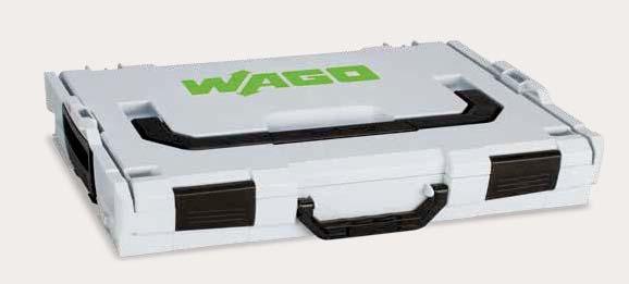
5 Volume, Rail-Mount Terminal Block Systems Contents Accessories, Jumpers Page 282, 2009 Series 202 Series Series 7 X-COM -SYSTEM 2-Conductor/-Pin Double-Deck Carrier Terminal Blocks 2.5 ( f- 870 Series 8 Matrix Patchboards with Push-Buttons, 32-Pole Slimline Version, for 9 Racks 726 Series 9 L-BOXX Splicing Connector Sets 887 Series 0 22 Series 3 Products highlighted in RED are new items for Spring 208 Rail-Mount Terminal Block Systems 3

6 Volume, Section Rail-Mount Terminal Blocks, TOPJOB S TOPJOB S Jumper and Push-in Type Wire Jumper 2002 Series and 2009 Series Jumper Push-in type wire jumper I N 8 A Conductor cross-section:.5 mm² Item No. Jumper; insulated; I N 30 A; orange Pack. Unit / (5x0) Item No. Pack. Unit Push-in type wire jumper; insulated; conductor cross-section:.5 mm²; L = 0 mm; for 200; 2002; 2003 and 2022 Series Rail-Mount Terminal Blocks red 2009-/ (0x0) blue 2009-/ (0x0) Rail-Mount Terminal Block Systems

7 Volume, Section Rail-Mount Terminal Blocks, TOPJOB S TOPJOB S Component Plug on Carrier Terminal Block 2.5 () mm² 202 Series Length of : 66.5 mm / 2.62 inch 2-conductor carrier terminal block 2 Length of : 76.8 mm / 3.02 inch 3-conductor carrier terminal block 3 Length of : 87.5 mm / 3.5 inch -conductor carrier terminal block Length of : 72.9 mm / 2.87 inch 2-conductor carrier terminal block with additional jumper slot 5 See application notes in our Full Line Catalog, Volume. Colored push-in type jumper bar Staggered jumper Push-in type wire jumper Pack. Item No. Unit Component plug; -pole; transparent housing; with fiber optics; 0.3 mm wide Component plug; 8-pole; transparent housing; with fiber optics; 20.7 mm wide Pack. Item No. Unit Component plug; 6-pole; transparent housing; with fiber optics; 5.5 mm wide Component plug; 0-pole; transparent housing; with fiber optics; 25.9 mm wide Accessories for carrier terminal blocks Appropriate marking systems: WMB/Mini-WSB/Marker Strips (see Full Line Catalog, Volume, Section 3) 2-conductor carrier terminal block; () mm² / 22 2 AWG 5.2 mm / inch wide gray End and intermediate plate; mm thick orange (x25) gray (x25) 3-conductor carrier terminal block; () mm² / 22 2 AWG 5.2 mm / inch wide gray End and intermediate plate; mm thick orange (x25) gray (x25) -conductor carrier terminal block; () mm² / 22 2 AWG 5.2 mm / inch wide gray End and intermediate plate; mm thick orange (x25) gray (x25) 2-conductor carrier terminal block; () mm² / 22 2 AWG 5.2 mm / inch wide gray End and intermediate plate; mm thick orange (x25) gray (x25) Protective warning marker; with black high-voltage symbol; for 5 terminal blocks Push-in type wire jumper; insulated; I N 8 A;.5 mm² Staggered jumper; insulated; I N 25 A; light gray 5 conductor cross-section 5 L = 60 mm L = 0 mm L = 250 mm Push-in type jumper bar; insulated; I N 25 A; light gray 5 2-way way way way way way way way way Push-in type jumper bar; insulated; I N 25 A; light gray to 3 to to 5 to 6 to 7 to 8 to 9 to (0x0) 00 (0x0) 00 (0x0) way 3-way -way 5-way 6-way 7-way 8-way 9-way 0-way -way 2-way WMB Multi marking system; white; 0 strips with 0 markers/card; stretchable from mm plain WMB Multi marking system; plain; 0 strips with 0 markers/card; stretchable from mm yellow red blue gray orange light green green violet / / / / / / / / yellow (x25) Rail-Mount Terminal Block Systems 5
 mm² 22 2 AWG 250 V/ kv/3; 0 A 23 00 V/6 kv/3; 0 A 2 Terminal block width: 5.2 mm / 0.205 inch L 0 2 mm / 0.39 0.7 inch 3 56,7 mm/2.32 in 0 mm/.33 in,3 mm/.7 in Conductor range: 0.")
8 Volume, Section 3 Installation Rail-Mount Terminal Blocks, TOPJOB S TOPJOB S Multilevel Installation Terminal Block 2.5 () mm²; 2003 Series () mm² 22 2 AWG 250 V/ kv/3; 0 A V/6 kv/3; 0 A 2 Terminal block width: 5.2 mm / inch L 0 2 mm / inch 3 56,7 mm/2.32 in 0 mm/.33 in,3 mm/.7 in Conductor range: 0.25 mm² s + f-st ; Push-in termination: 0.75 mm² s and mm² insulated ferrules, 2 mm V/ 00 V = rated voltage kv/ 6 kv = rated surge voltage 3 = pollution degree (see Full Line Catalog, Volume, Section ) V/ kv potential ground 00 V/6 kv potential potential Pack. Item No. Unit Multilevel installation terminal block; carrier terminal block without knife disconnect; blue middle-deck, green-yellow lower-deck printing; gray Maximum current depends on accessories used. L/N/PE Item-Specific Accessories N/L-test plug adapter; for vertical test slot; gray 2-pole (x25) N-test plug adapter; for vertical test slot; gray -pole (x25) End and intermediate plate; for use without fuse plug; 0.8 mm thick orange (x25) Fuse plug with pull-tab; for (5 x 20) mm miniature metric fuses Electrical ratings are given by the fuse. gray End and intermediate plate; only for use with fuse plugs; mm thick orange (x25) Double-fuse plug; for (5 x 20) mm miniature metric fuses Electrical ratings are given by the fuse. gray Double-fuse plug; for (5 x 20) mm miniature metric fuse; with LED; gray Electrical ratings are given by the fuse and blown fuse indication. Leakage current in case of a blown fuse: LED 0.25 ma gray / End and intermediate plate; mm thick; only for use with double-fuse plugs orange (x25) 6 Rail-Mount Terminal Block Systems
9 Rail-Mount Terminal Block Systems 7
 mm²; 870 Series 0.08 2.5 ( f-st ) mm² 28 2 AWG 500 V/6 kv/3 2 I N 6 A Terminal block width: 5 mm / 0.97 inch L 6 7 mm / 0.2 0.28 inch 0.08 2.5 ( f-st ) mm² 28 2 AWG Terminal block width: 5 mm / 0.")
 3 See application notes in our Full Line Catalog, Volume.")
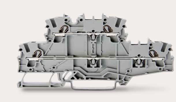
10 Volume, Section 6 Rail-Mount Terminal Blocks with a Pluggable Connector, X-COM -SYSTEM, Classic X-COM -SYSTEM 2-Conducto/-Pin Double-Deck Carrier Terminal Block 2.5 ( f-st ) mm²; 870 Series ( f-st ) mm² 28 2 AWG 500 V/6 kv/3 2 I N 6 A Terminal block width: 5 mm / 0.97 inch L 6 7 mm / inch ( f-st ) mm² 28 2 AWG Terminal block width: 5 mm / 0.97 inch L 6 7 mm / inch 52,3 mm/2.06 in 9 mm/3.58 in 39,8 mm/.57 in 52,3 mm/2.06 in 9 mm/3.58 in 39,8 mm/.57 in Max. insulation diameter:. mm V = Rated voltage 6 kv = Rated surge voltage 3 = Pollution degree (see Full Line Catalog, Volume, Section ) 3 See application notes in our Full Line Catalog, Volume. Insulation stop Note: 2-conductor female plugs cannot be used. 6 Pack. Item No. Unit 2-conductor/-pin double-deck carrier terminal block; through/through terminal block; gray housing L/L conductor/2-pin double-deck carrier terminal block; -conductor/2-pin through terminal block; internally commoned; violet conductor entry; gray housing Pack. Item No. Unit -conductor/2-pin double-deck carrier block; -conductor/2-pin ground conductor block; internally commoned; green-yellow housing PE Accessories Appropriate marking systems: Mini-WSB/WMB Push-in type jumper bar; insulated; I N 8 A; light gray / / (8x25) / (x25) L Delta jumper; insulated; I N 8 A; light gray Accessories End and intermediate plate; mm thick orange gray Insulation stop; 5 pcs/strip; mm² s 3 (0. mm² f-st ) white Insulation stop; 5 pcs/strip; mm² 3 light gray Insulation stop; 5 pcs/strip; 0.75 mm² 3 dark gray Coding pin; for coding female plugs orange Pin cover; with Mini-WSB marker slot gray orange conductor female plug; angled Appropriate marking systems: Mini-WSB/WMB 00 (x25) 00 (x25) 200 (8x25) 200 (8x25) 200 (8x25) 00 (x25) 00 (x25) 00 (x25) Push-in type jumper bar; insulated; I N 8 A; light gray 2-way 3-way -way 5-way 6-way 7-way 8-way 9-way 0-way Push-in type jumper bar; insulated; I N 8 A; light gray to 3 to to 5 to 6 to 7 to 8 to 9 to (8x25) 200 (8x25) 00 (x25) 00 (x25) 00 (x25) 00 (x25) 00 (x25) 00 (x25) 50 (2x25) (8x25) (8x25) (x25) (x25) (x25) (x25) (x25) (2x25) / (x25) gray 769-0/ connector female plug; straight gray Rail-Mount Terminal Block Systems
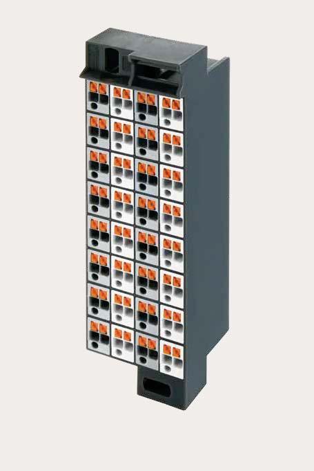
11 Volume, Section Matrix Patchboards Matrix Patchboard with Push-Buttons; 32-Pole Slimline Version; for 9 Racks 726 Series Side : 32 x mm² 28 6 AWG Side : 32 x mm² 28 6 AWG Side 2: 32 x mm² 28 6 AWG Side 2: 32 x mm² 28 6 AWG 800 V/8 kv/3 800 V/8 kv/3 I N 0 A I N 0 A L 0 mm / 0.39 inch L 0 mm / 0.39 inch 500 V = Rated voltage 8 kv = Rated surge voltage 3 = Pollution degree (see Full Line Catalog, Volume, Section ) 2 See application notes in our Full Line Catalog, Volume. Decade marker carrier Item No. Pack. Pack. Item No. Unit Unit Matrix patchboard; dark gray frame; blue modules; for Matrix patchboard; dark gray frame; blue modules; for 9 racks 9 racks without marking Marking Matrix patchboard; dark gray frame; white/gray modules; vertical module marking on sides and 2; for 9 racks without marking Matrix Patchboard Accessories Wire commoning chain; insulated; 32 connections; I N 6 A; max. 50 V; 0.5 mm² gray WMB Inline; plain; stretchable from mm;,500 WMB markers (5 mm) per reel white Marking strip; plain; mm wide; 50 m reel Patching side 33, Field side 2,9 5 Patching side 33, Field side 2,9 5 white WMB Multi marking system; white; 0 strips with 0 markers/card; stretchable from mm plain WMB Multi marking system; plain; 0 strips with 0 markers/card; stretchable from mm yellow / red / blue / gray / orange / light green / green / violet / Decade marker carrier; for matrix patchboards 2 dark gray ,5 9, Operating tool with a partially insulated shaft; type ; (2.5 x 0.) mm blade , , Test probe; 2 mm Ø; min. 2 mm lon; uninsulated tip; not offered by WAGO (e.g., MultiContact XPP-80/2-6) ,5,5 5 9,7 9,5,5 5 9,7 29,9 3,6 29,9 3,6 Dimensions (in mm): Dimensions (in mm): Rail-Mount Terminal Block Systems 9


12 Volume, Section 2 Splicing Connectors Splicing Connector Set 887 Series Splicing Connector Set Splicing Connector Set Splicing Connector Set Pack. Item No. Unit Splicing connector set; L-BOXX 02; 22, 2273 Series Item No. Splicing connector set; L-BOXX 02; 22 Series Pack. Unit Item No. Splicing connector set; L-BOXX Mini; 22 Series Pack. Unit Contains: COMPACT PUSH WIRE Connectors for Junction Boxes white 2 x mm² orange 3 x mm² red x mm² yellow 5 x mm² light gray 8 x mm² COMPACT Splicing Connectors transparent 2 x 0. mm² transparent 3 x 0. mm² transparent 5 x 0. mm² Mounting carrier orange Contains: COMPACT Splicing Connectors 2 x 0. mm² x 0. mm² x 0. mm² Mounting carrier orange Contains: COMPACT Splicing Connectors 2 x 0. mm² x 0. mm² x 0. mm² Mounting carrier orange Mounting carrier orange Rail-Mount Terminal Block Systems

13 Volume, Section 2 Splicing Connectors Splicing Connector Set 887 Series Splicing Connector Set Splicing Connector Set Splicing Connector Set Item No. Pack. Pack. Pack. Item No. Item No. Unit Unit Unit Splicing connector set; L-BOXX Mini; 2273 Series Splicing connector set; L-BOXX Mini; 22, 2273, 773, 22, 23 Series Splicing connector set; L-BOXX Mini; 22, 2273 Series Contains: COMPACT PUSH WIRE Connectors for Junction Boxes white 2 x mm² orange 3 x mm² red x mm² yellow 5 x mm² light gray 8 x mm² Mounting carrier orange Contains: COMPACT PUSH WIRE Connectors for Junction Boxes orange 3 x mm² yellow 5 x mm² light gray 8 x mm² COMPACT Splicing Connectors transparent 2 x 0. mm² transparent 3 x 0. mm² transparent 5 x 0. mm² Lighting Connectors white 2 x 2.5 mm² s PUSH WIRE Connectors for Junction Boxes red mm² s+str MICRO PUSH WIRE Connectors for Junction Boxes dark gray x mm Ø dark gray 8 x mm Ø Contains: COMPACT PUSH WIRE Connectors for Junction Boxes orange 3 x mm² yellow 5 x mm² light gray 8 x mm² COMPACT Splicing Connectors transparent 2 x 0. mm² transparent 3 x 0. mm² transparent 5 x 0. mm² Mounting carrier orange Mounting carrier orange Rail-Mount Terminal Block Systems


.")


14 Volume, Section 2 Splicing Connectors COMPACT Splicing Connectors for All Conductor Types 22 Series Description and Installation Strip conductor to mm (0.3 inch). Termination: Lift the lever to open the clamping unit and insert a stripped conductor. Then, lower the lever to close the clamp. Wiring fine-stranded conductors in a junction box. Custom low-voltage lighting systems 2 Wiring fine-stranded conductors in a junction box. Lighting distribution in ceiling canopy Pendant light connection in suspended ceilings CAGE CLAMP terminates the following copper conductors: solid stranded fine-stranded, also with tinned single strands fine-stranded, tip-bonded 2 Rail-Mount Terminal Block Systems

: 05 C; ambient temperature (max.): 85 C (T85) 22-62 500 (0x50) Pack.")
: 85 C (T85) 22-63 300 (0x30) 6 2 0, 0, 0, Dimensions in mm 2, Dimensions in mm 2, 22,9 Compact, lever-operated splicing connectors: They connect up to five stripped conductors from 0.")
15 Volume, Section 2 Splicing Connectors COMPACT Splicing Connectors for All Conductor Types 6 mm²; 22 Series mm² 20 0 AWG mm² 20 0 AWG 50 V/ kv/2 50 V/ kv/2 I N A I N A L 2 mm / inch L 2 mm / inch In grounded power lines 50 V = Rated voltage kv = Rated surge voltage 2 = Pollution degree (see Full Line Catalog, Volume, Section ) Pack. Item No. Unit COMPACT PUSH WIRE connector for junction boxes; 2-wire connector; with levers; continuous operating temperature (max.): 05 C; ambient temperature (max.): 85 C (T85) (0x50) Pack. Item No. Unit COMPACT PUSH WIRE connector for junction boxes; 3-wire connector; with levers; continuous operating temperature (max.): 05 C; ambient temperature (max.): 85 C (T85) (0x30) 6 2 0, 0, 0, Dimensions in mm 2, Dimensions in mm 2, 22,9 Compact, lever-operated splicing connectors: They connect up to five stripped conductors from 0.5 to 6 mm² (20 0 AWG) without tools! How these work: Pull up one of the orange operating levers to open the clamping unit. Then insert the conductor and push the lever back down, flush with the connector housing. 28,3 mm/. in Safety: The specially designed rest position of the lever reliably prevents accidental unclamping of a connected conductor. Application safety, for any type of conductor (solid, stranded, fine-stranded), is confirmed by approvals like ENEC or UL. 8,2 mm/3.7 in Item No. Pack. Pack. Item No. Unit Unit Mounting carrier; for 2-, 3- and 5-conductor splicing connectors; 9.3 mm wide; 28.3 mm high; 9.2 mm deep COMPACT PUSH WIRE connector for junction boxes; 5-wire connector; with levers; continuous operating temperature (max.): 05 C; ambient temperature (max.): 85 C (T85) orange (5x0) (0x5) ENEC is the European mark for electrical products that demonstrates compliance with European safety standards. The ENEC mark is subjected to the same EN standards as the VDE mark. While the VDE mark is only permitted in Germany, the ENEC mark is accepted in more than 20 European countries. Accessories; item-specific Self-adhesive marking strips; 5 mm high; 8 self-adhesive strips per card; plain white , 36,7 Dimensions in mm Rail-Mount Terminal Block Systems 3

16 Volume 2, PCB Terminal Blocks and Connectors


17 Volume 2, PCB Terminal Blocks and Connectors Contents Nominal Cross-Section Series Page PCB Terminal Blocks with Levers; Push-in CAGE CLAMP PCB Terminal Blocks with Screwdriver Actuation; Push-in CAGE CLAMP Through-Board SMD PCB Terminal Blocks; Push-in CAGE CLAMP SMD PCB Terminal Blocks; Push-in CAGE CLAMP ; PUSH WIRE Board-to-Board Links for SMD PCB Terminal Blocks MCS MULTI CONNECTION SYSTEM MAXI 6 Female Connectors; Push-in CAGE CLAMP MCS MULTI CONNECTION SYSTEM MAXI 6 THT Male Headers MCS MULTI CONNECTION SYSTEM MAXI 6 Male Connectors; Push-in CAGE CLAMP MCS MULTI CONNECTION SYSTEM MAXI 6 Snap-In Frames Lockout Pins for Snap-In Frames PCB Terminal Blocks and Connectors 5

18 Volume 2, Section PCB Terminal Blocks PCB Terminal Block with Levers; mm² Pin Spacing: 5 mm; 7.5 mm;.5 mm 260 Series PCB terminal block with lever-actuated Push-in CAGE CLAMP connection Push-in termination of solid and ferruled conductors Intuitive and tool-free operation Several clamping units can be held open simultaneously convenient for terminating multi-core cables Testing can be performed both parallel and perpendicular to conductor entry Current-Carrying Capacity Curve Pin spacing: 5 mm / Conductor cross-section: mm² "f-st" Based on: EN / Reduction factor: Current in A 0 30 Electrical Data for Pin Spacing 5 mm 0.97 inch 7.5 mm inch.5 mm 0.53 inch Ratings per* IEC/EN IEC/EN IEC/EN Nominal voltage (III / 3) 320 V 630 V 000 V Rated impulse voltage (III / 3) kv 6 kv 8 kv Rated voltage (III / 2) 00 V 630 V 000 V Rated surge voltage (III / 2) kv 6 kv 8 kv Rated voltage (II / 2) 630 V 000 V 000 V Rated surge voltage (II / 2) kv 6 kv 8 kv Rated current 32 A 32 A 32 A Ambient operating temperature in C 2-, -, 6-, 2- pole Conductor rated current Approvals per UL 059 UL 059 UL 059 Rated voltage UL (Use Group B) 300 V 300 V 600 V Rated current UL (Use Group B) 20 A 20 A 20 A Rated voltage UL (Use Group C) 300 V 600 V Rated current UL (Use Group C) 20 A 20 A Rated voltage UL (Use Group D) 300 V 600 V Rated current UL (Use Group D) 0 A 5 A Connection Data Connection technology Push-in CAGE CLAMP Strip length 9 mm / inch Conductor entry angle to the PCB 0 Conductor cross-sections Solid conductor Fine-stranded conductor Fine-stranded conductor with insulated ferrule Fine-stranded conductor with uninsulated ferrule Fine-stranded conductor, with twin ferrule Solder Pin Data Solder pin length Solder pin dimensions Drilled hole diameter mm 0.8 x mm mm Pollution degree 2 Material Data Material group I Insulation material Polyamide 66 (PA 66) Flammability class per UL9 V0 Limit temperature range +05 C Clamping spring material Chrome nickel spring steel (CrNi) Contact material Electrolytic copper (E Cu ) Contact plating Tin-plated Additional technical information, see Volume 2, Section 3 Approvals and corresponding ratings, visit 6 PCB Terminal Blocks and Connectors


 pin spacing PCB terminal block with levers; conductor entry parallel to PCB; 2 solder pins/pole; gray;.5 mm (0.53 inch) pin spacing Pole No. Item No. Pack.")
19 Volume 2, Section PCB Terminal Blocks PCB Terminal Block with Levers; mm² Pin Spacing: 5 mm; 7.5 mm;.5 mm 260 Series Dimensions (in mm): Dimensions (in mm): Dimensions (in mm): 0,9 0,9 0,9,5 7,5 3,8 L 2,7 Ø,3 8,2 2,9 25,7 6,7 25,7 6,7 8,2 6,3 9,2 0,8 5,2,5,5 3,8 L 2,7 8,2 6,3 9,2 0,8 5,2 Ø,3 8,2 2,9 25,7 6,7,5 5 3,8 L 2,7 8,2 6,3 9,2 0,8 5,2 Ø,3 8,2 2,9 5 5,5 PCB terminal block with levers; conductor entry parallel to PCB; 2 solder pins/pole; gray; 5 mm (0.97 inch) pin spacing PCB terminal block with levers; conductor entry parallel to PCB; 2 solder pins/pole; gray; 7.5 mm (0.295 inch) pin spacing PCB terminal block with levers; conductor entry parallel to PCB; 2 solder pins/pole; gray;.5 mm (0.53 inch) pin spacing Pole No. Item No. Pack. Unit Pole No. Item No. Pack. Unit Pole No. Item No. Pack. Unit Available upon request (depending on quantity required): Other pole numbers Other colors Direct marking PCB Terminal Blocks and Connectors 7
20 Volume 2, Section PCB Terminal Blocks PCB Terminal Block with Levers; mm² Pin Spacing: 5 mm; 7.5 mm;.5 mm 260 Series PCB terminal block with lever-actuated Push-in CAGE CLAMP connection Push-in termination of solid and ferruled conductors Intuitive and tool-free operation Several clamping units can be held open simultaneously convenient for terminating multi-core cables Testing can be performed both parallel and perpendicular to conductor entry Current-Carrying Capacity Curve Pin spacing: 5 mm / Conductor cross-section: mm² "f-st" Based on: EN / Reduction factor: Current in A 0 30 Electrical Data for Pin Spacing 5 mm 0.97 inch 7.5 mm inch.5 mm 0.53 inch Ratings per* IEC/EN IEC/EN IEC/EN Nominal voltage (III / 3) 320 V 630 V 000 V Rated impulse voltage (III / 3) kv 6 kv 8 kv Rated voltage (III / 2) 00 V 630 V 000 V Rated surge voltage (III / 2) kv 6 kv 8 kv Rated voltage (II / 2) 630 V 000 V 000 V Rated surge voltage (II / 2) kv 6 kv 8 kv Rated current 32 A 32 A 32 A Ambient operating temperature in C 2-, -, 6-, 2- pole Conductor rated current Approvals per UL 059 UL 059 UL 059 Rated voltage UL (Use Group B) 300 V 300 V 600 V Rated current UL (Use Group B) 20 A 20 A 20 A Rated voltage UL (Use Group C) 300 V 600 V Rated current UL (Use Group C) 20 A 20 A Rated voltage UL (Use Group D) 300 V 600 V Rated current UL (Use Group D) 0 A 5 A Connection Data Connection technology Push-in CAGE CLAMP Strip length 9 mm / inch Conductor entry angle to the PCB 90 Conductor cross-sections Solid conductor Fine-stranded conductor Fine-stranded conductor with insulated ferrule Fine-stranded conductor with uninsulated ferrule Fine-stranded conductor, with twin ferrule Solder Pin Data Solder pin length Solder pin dimensions Drilled hole diameter mm 0.8 x mm mm Pollution degree 2 Material Data Material group I Insulation material Polyamide 66 (PA 66) Flammability class per UL9 V0 Limit temperature range +05 C Clamping spring material Chrome nickel spring steel (CrNi) Contact material Electrolytic copper (E Cu ) Contact plating Tin-plated Additional technical information, see Volume 2, Section 3 Approvals and corresponding ratings, visit 8 PCB Terminal Blocks and Connectors


 pin spacing PCB terminal block with levers; conductor entry perpendicular to PCB; 2 solder pins/pole; gray;.5 mm (0.53 inch) pin spacing Pole No. Item No. Pack.")
21 Volume 2, Section PCB Terminal Blocks PCB Terminal Block with Levers; mm² Pin Spacing: 5 mm; 7.5 mm;.5 mm 260 Series Dimensions (in mm): Dimensions (in mm): Dimensions (in mm): 0,9 0,9 0,9 5 L 2,7,5 3,8 0,8 8,2 6,7 25,8 8, 2,3 3,6,5 7,5 3,8 L 2,7 0,8 8,2 6,7 25,8 8, 2,3 3,6,5,5 3,8 L 2,7 0,8 8,2 6,7 25,8 8, 2,3 3,6 8,2,9 Ø,3 8,2,9 5 7,5,5 Ø,3 8,2,9 Ø,3 PCB terminal block with levers; conductor entry perpendicular to PCB; 2 solder pins/pole; gray; 5 mm (0.97 inch) pin spacing PCB terminal block with levers; conductor entry perpendicular to PCB; 2 solder pins/pole; gray; 7.5 mm (0.295 inch) pin spacing PCB terminal block with levers; conductor entry perpendicular to PCB; 2 solder pins/pole; gray;.5 mm (0.53 inch) pin spacing Pole No. Item No. Pack. Unit Pole No. Item No. Pack. Unit Pole No. Item No. Pack. Unit Available upon request (depending on quantity required): Other pole numbers Other colors Direct marking PCB Terminal Blocks and Connectors 9
22 Volume 2, Section PCB Terminal Blocks PCB Terminal Block with Levers; 6 mm² Pin Spacing: 7.5 mm 2606 Series PCB terminal block with lever-actuated Push-in CAGE CLAMP connection Push-in termination of solid and ferruled conductors Intuitive and tool-free operation Several clamping units can be held open simultaneously convenient for terminating multi-core cables Testing can be performed both parallel and perpendicular to conductor entry Current-Carrying Capacity Curve Pin spacing: 7,5 mm / Conductor cross-section: 6 mm 2 "f-st" Based on: EN / Reduction factor: Current in A , -, 6-, 2- pole Ambient operating temperature in C Conductor rated current Electrical Data Ratings per* IEC/EN Nominal voltage (III / 3) 800 V Rated impulse voltage (III / 3) 8 kv Rated voltage (III / 2) 000 V Rated surge voltage (III / 2) 8 kv Rated voltage (II / 2) 000 V Rated surge voltage (II / 2) 8 kv Rated current A Approvals per UL 059 Rated voltage UL (Use Group B) 600 V Rated current UL (Use Group B) 3 A Rated voltage UL (Use Group C) 600 V Rated current UL (Use Group C) 3 A Connection Data Connection technology Push-in CAGE CLAMP Strip length 3 mm / inch Conductor entry angle to the PCB 0 Conductor cross-sections Solid conductor Fine-stranded conductor Fine-stranded conductor with insulated ferrule Fine-stranded conductor with uninsulated ferrule Fine-stranded conductor, with twin ferrule Solder Pin Data Solder pin length Solder pin dimensions Drilled hole diameter mm.5 x.2 mm mm Material Data Material group I Insulation material Polyamide 66 (PA 66) Flammability class per UL9 V0 Limit temperature range +05 C Clamping spring material Chrome nickel spring steel (CrNi) Contact material Electrolytic copper (E Cu ) Contact plating Tin-plated Pollution degree 2 UL/CSA approval pending Additional technical information, see Volume 2, Section 3 Approvals and corresponding ratings, visit 20 PCB Terminal Blocks and Connectors
: Dimensions (in mm):,,5,,5,5 7,5 L 5,5 7,5 2 Ø 2 (3,5) 2,5 2 2 36,7 36,7,5 L Ø 2 (3,5),2 2,5 2 2,3,2 2,5 2 2,3 2,5 PCB terminal block with lever; conductor entry")

23 Volume 2, Section PCB Terminal Blocks PCB Terminal Block with Levers; 6 mm² Pin Spacing: 7.5 mm 2606 Series Dimensions (in mm): Dimensions (in mm):,,5,,5,5 7,5 L 5,5 7,5 2 Ø 2 (3,5) 2, ,7 36,7,5 L Ø 2 (3,5),2 2,5 2 2,3,2 2,5 2 2,3 2,5 PCB terminal block with lever; conductor entry parallel to PCB; 2 solder pins/pole; gray; 7.5 mm (0.295 inch) pin spacing PCB terminal block with levers; conductor entry parallel to PCB; staggered solder pin/pole; gray; 7.5 mm (0.295 inch) pin spacing Pole No. Item No. Pack. Unit Pole No. Item No. Pack. Unit / / / / / / / / / / / Available upon request (depending on quantity required): Other pole numbers Other colors Other pin spacing Direct marking PCB Terminal Blocks and Connectors 2
24 Volume 2, Section PCB Terminal Blocks PCB Terminal Block with Levers; 6 mm² Pin Spacing: 7.5 mm 2606 Series PCB terminal block with lever-actuated Push-in CAGE CLAMP connection Push-in termination of solid and ferruled conductors Intuitive and tool-free operation Several clamping units can be held open simultaneously convenient for terminating multi-core cables Testing can be performed both parallel and perpendicular to conductor entry Current-Carrying Capacity Curve Pin spacing: 7,5 mm / Conductor cross-section: 6 mm 2 "f-st" Based on: EN / Reduction factor: Current in A Electrical Data Ratings per* IEC/EN Nominal voltage (III / 3) 800 V Rated impulse voltage (III / 3) 8 kv Rated voltage (III / 2) 000 V Rated surge voltage (III / 2) 8 kv Rated voltage (II / 2) 000 V Rated surge voltage (II / 2) 8 kv Rated current A Approvals per UL 059 Rated voltage UL (Use Group B) 600 V Rated current UL (Use Group B) 3 A Rated voltage UL (Use Group C) 600 V Rated current UL (Use Group C) 3 A 2-, -, 6-, 2- pole Ambient operating temperature in C Conductor rated current Connection Data Connection technology Push-in CAGE CLAMP Strip length 3 mm / inch Conductor entry angle to the PCB 90 Conductor cross-sections Solid conductor Fine-stranded conductor Fine-stranded conductor with insulated ferrule Fine-stranded conductor with uninsulated ferrule Fine-stranded conductor, with twin ferrule Solder Pin Data Solder pin length Solder pin dimensions Drilled hole diameter mm.5 x.2 mm mm Material Data Material group I Insulation material Polyamide 66 (PA 66) Flammability class per UL9 V0 Limit temperature range +05 C Clamping spring material Chrome nickel spring steel (CrNi) Contact material Electrolytic copper (E Cu ) Contact plating Tin-plated Pollution degree 2 UL/CSA approval pending Additional technical information, see Volume 2, Section 3 Approvals and corresponding ratings, visit 22 PCB Terminal Blocks and Connectors
:,,5 Dimensions (in mm):,,5 27 23,7 27 23,7,5 L,2 3,8 (3,5) 2,5 2 Ø 2 36,7,5 (3,5) 7,5 L 5,5 7,5 Ø 2,2 2,5 2 36,7 3,8 2,5 7,7 2,5 Insert solid conductors via")
25 Volume 2, Section PCB Terminal Blocks PCB Terminal Block with Levers; 6 mm² Pin Spacing: 7.5 mm 2606 Series Dimensions (in mm):,,5 Dimensions (in mm):,, , ,7,5 L,2 3,8 (3,5) 2,5 2 Ø 2 36,7,5 (3,5) 7,5 L 5,5 7,5 Ø 2,2 2,5 2 36,7 3,8 2,5 7,7 2,5 Insert solid conductors via push-in termination. all conductors via operating lever. PCB terminal block with lever; conductor entry perpendicular to PCB; 2 solder pins/pole; gray; 7.5 mm (0.295 inch) pin spacing PCB terminal block with levers; conductor entry perpendicular to PCB; staggered solder pin/pole; gray; 7.5 mm (0.295 inch) pin spacing Pole No. Item No. Pack. Unit Pole No. Item No. Pack. Unit / / / / / / / / / / / Available upon request (depending on quantity required): Other pole numbers Other colors Other pin spacing Direct marking PCB Terminal Blocks and Connectors 23
26 Volume 2, Section PCB Terminal Blocks PCB Terminal Block with Levers; 6 mm² Pin Spacing: 0 mm 266 Series PCB terminal block with lever-actuated Push-in CAGE CLAMP connection Push-in termination of solid and ferruled conductors Intuitive and tool-free operation Several clamping units can be held open simultaneously convenient for terminating multi-core cables Testing can be performed both parallel and perpendicular to conductor entry Current-Carrying Capacity Curve Pin spacing: 0 mm / Conductor cross-section: 6 mm 2 "f-st" Based on: EN / Reduction factor: Current in A , -, 6-, 2- pole Ambient operating temperature in C Conductor rated current Electrical Data Ratings per* IEC/EN Nominal voltage (III / 3) 000 V Rated impulse voltage (III / 3) 8 kv Rated voltage (III / 2) 000 V Rated surge voltage (III / 2) 8 kv Rated voltage (II / 2) 000 V Rated surge voltage (II / 2) 8 kv Rated current 76 A Approvals per UL 059 Rated voltage UL (Use Group B) 600 V Rated current UL (Use Group B) 66 A Rated voltage UL (Use Group C) 600 V Rated current UL (Use Group C) 66 A Connection Data Connection technology Push-in CAGE CLAMP Strip length 8 20 mm / inch Conductor entry angle to the PCB 0 Conductor cross-sections Solid conductor Fine-stranded conductor Fine-stranded conductor with insulated ferrule Fine-stranded conductor with uninsulated ferrule Fine-stranded conductor, with twin ferrule Solder Pin Data Solder pin length Solder pin dimensions Drilled hole diameter mm.2 x.2 mm mm Material Data Material group I Insulation material Polyamide 66 (PA 66) Flammability class per UL9 V0 Limit temperature range +05 C Clamping spring material Chrome nickel spring steel (CrNi) Contact material Electrolytic copper (E Cu ) Contact plating Tin-plated Pollution degree 2 UL/CSA approval pending Additional technical information, see Volume 2, Section 3 Approvals and corresponding ratings, visit 2 PCB Terminal Blocks and Connectors
:,3,5 Dimensions (in mm):,3,5,2 2,5 5 L 2, Ø,7,2 5 0,2 27,8 32 5 33,2")
27 Volume 2, Section PCB Terminal Blocks PCB Terminal Block with Levers; 6 mm² Pin Spacing: 0 mm 266 Series Dimensions (in mm):,3,5 Dimensions (in mm):,3,5,2 2,5 5 L 2, Ø,7,2 5 0,2 27, ,2 9,8,2 2,5 0 5 L, 2, Ø,7,2 5 0,2 27, ,6 33,2 9,8 PCB terminal block with lever; conductor entry parallel to PCB; 6 solder pins/pole; gray; 0 mm (0.39 inch) pin spacing 0 5 2,5 PCB terminal block with levers; conductor entry parallel to PCB; 3 staggered solder pins/pole; gray; 0 mm (0.39 inch) pin spacing Pole No. Item No. Pack. Unit Pole No. Item No. Pack. Unit / / / / / / / / / / / Available upon request (depending on quantity required): Other pole numbers Other colors Other pin spacing Direct marking PCB Terminal Blocks and Connectors 25

28 Volume 2, Section PCB Terminal Blocks PCB Terminal Block with Levers; 6 mm² Pin Spacing: 0 mm 266 Series PCB terminal block with lever-actuated Push-in CAGE CLAMP connection Push-in termination of solid and ferruled conductors Intuitive and tool-free operation Several clamping units can be held open simultaneously convenient for terminating multi-core cables Testing can be performed both parallel and perpendicular to conductor entry 0 00 Current-Carrying Capacity Curve Pin spacing: 0 mm / Conductor cross-section: 6 mm 2 "f-st" Based on: EN / Reduction factor: Current in A , -, 6-, 2- pole Ambient operating temperature in C Conductor rated current Electrical Data Ratings per* IEC/EN Nominal voltage (III / 3) 000 V Rated impulse voltage (III / 3) 8 kv Rated voltage (III / 2) 000 V Rated surge voltage (III / 2) 8 kv Rated voltage (II / 2) 000 V Rated surge voltage (II / 2) 8 kv Rated current 76 A Approvals per UL 059 Rated voltage UL (Use Group B) 600 V Rated current UL (Use Group B) 66 A Rated voltage UL (Use Group C) 600 V Rated current UL (Use Group C) 66 A Connection Data Connection technology Push-in CAGE CLAMP Strip length 8 20 mm / inch Conductor entry angle to the PCB 90 Conductor cross-sections Solid conductor Fine-stranded conductor Fine-stranded conductor with insulated ferrule Fine-stranded conductor with uninsulated ferrule Fine-stranded conductor, with twin ferrule Solder Pin Data Solder pin length Solder pin dimensions Drilled hole diameter mm.2 x.2 mm mm Material Data Material group I Insulation material Polyamide 66 (PA 66) Flammability class per UL9 V0 Limit temperature range +05 C Clamping spring material Chrome nickel spring steel (CrNi) Contact material Electrolytic copper (E Cu ) Contact plating Tin-plated Pollution degree 2 UL/CSA approval pending Additional technical information, see Volume 2, Section 3 Approvals and corresponding ratings, visit 26 PCB Terminal Blocks and Connectors
: Dimensions (in mm):,3,5,3,5 30 3,2 30 3,2,2 L 5 2,5 2, Ø,7,2 5 29, 6,2")

29 Volume 2, Section PCB Terminal Blocks PCB Terminal Block with Levers; 6 mm² Pin Spacing: 0 mm 266 Series Dimensions (in mm): Dimensions (in mm):,3,5,3,5 30 3,2 30 3,2,2 L 5 2,5 2, Ø,7,2 5 29, 6,2 2,5, , 5 L 29, ,5 Ø,7 0 5 Insert solid conductors via push-in termination. all conductors via operating lever. PCB terminal block with lever; conductor entry perpendicular to PCB; 6 solder pins/pole; gray; 0 mm (0.39 inch) pin spacing PCB terminal block with levers; conductor entry perpendicular to PCB; 3 staggered solder pins/pole; gray; 0 mm (0.39 inch) pin spacing Pole No. Item No. Pack. Unit Pole No. Item No. Pack. Unit / / / / / / / / / / / Available upon request (depending on quantity required): Other pole numbers Other colors Other pin spacing Direct marking PCB Terminal Blocks and Connectors 27

30 Volume 2, Section PCB Terminal Blocks PCB Terminal Block; mm² Pin Spacing: 5 mm; 7.5 mm;.5 mm 262 Series PCB terminal block with Push-in CAGE CLAMP connection Push-in termination of solid and ferruled conductors Ideal for panel feedthrough applications via operation parallel to conductor entry Testing can be performed both parallel and perpendicular to conductor entry Current-Carrying Capacity Curve Pin spacing: 5 mm / Conductor cross-section: mm² "f-st" Based on: EN / Reduction factor: Current in A 0 30 Electrical Data for Pin Spacing 5 mm 0.97 inch 7.5 mm inch.5 mm 0.53 inch Ratings per* IEC/EN IEC/EN IEC/EN Nominal voltage (III / 3) 320 V 630 V 000 V Rated impulse voltage (III / 3) kv 6 kv 8 kv Rated voltage (III / 2) 00 V 630 V 000 V Rated surge voltage (III / 2) kv 6 kv 8 kv Rated voltage (II / 2) 630 V 000 V 000 V Rated surge voltage (II / 2) kv 6 kv 8 kv Rated current 32 A 32 A 32 A Ambient operating temperature in C 2-, -, 6-, 2- pole Conductor rated current Approvals per UL 059 UL 059 UL 059 Rated voltage UL (Use Group B) 300 V 300 V 600 V Rated current UL (Use Group B) 26 A 26 A 26 A Rated voltage UL (Use Group C) 50 V 600 V Rated current UL (Use Group C) 26 A 26 A Rated voltage UL (Use Group D) 300 V 300 V Rated current UL (Use Group D) 0 A 0 A Connection Data Connection technology Push-in CAGE CLAMP Strip length 0 2 mm / inch Conductor entry angle to the PCB 0 Conductor cross-sections Solid conductor Fine-stranded conductor Fine-stranded conductor with insulated ferrule Fine-stranded conductor with uninsulated ferrule Fine-stranded conductor, with twin ferrule Solder Pin Data Solder pin length Solder pin dimensions Drilled hole diameter mm 0.8 x mm mm Pollution degree 2 Material Data Material group I Insulation material Polyamide 66 (PA 66) Flammability class per UL9 V0 Limit temperature range +05 C Clamping spring material Chrome nickel spring steel (CrNi) Contact material Electrolytic copper (E Cu ) Contact plating Tin-plated Additional technical information, see Volume 2, Section 3 Approvals and corresponding ratings, visit 28 PCB Terminal Blocks and Connectors
31 Volume 2, Section PCB Terminal Blocks PCB Terminal Block; mm² Pin Spacing: 5 mm; 7.5 mm;.5 mm 262 Series Dimensions (in mm): Dimensions (in mm): Dimensions (in mm): 5, 5, 5, 5 L 2,3,5,2 0,8 8,2 5,6 6,3 7,5 L 2,3,5,2 0,8 8,2 5,6 6,3,5 L 2,3,5,2 0,8 8,2 5,6 6,3 8,2 2,55 5 Ø,3 8,2 2,55 Ø,3 7,5 8,2 2,55 Ø,3,5 PCB terminal block; conductor entry parallel to PCB; 2 solder pins/pole; gray; 5 mm (0.97 inch) pin spacing PCB terminal block; conductor entry parallel to PCB; 2 solder pins/pole; gray; 7.5 mm (0.295 inch) pin spacing PCB terminal block; conductor entry parallel to PCB; 2 solder pins/pole; gray;.5 mm (0.53 inch) pin spacing Pole No. Item No. Pack. Unit Pole No. Item No. Pack. Unit Pole No. Item No. Pack. Unit Available upon request (depending on quantity required): Other pole numbers Other colors Direct marking PCB Terminal Blocks and Connectors 29
32 Volume 2, Section PCB Terminal Blocks PCB Terminal Block; mm² Pin Spacing: 5 mm; 7.5 mm;.5 mm 262 Series PCB terminal block with Push-in CAGE CLAMP connection Push-in termination of solid and ferruled conductors Ideal for panel feedthrough applications via operation parallel to conductor entry Testing can be performed both parallel and perpendicular to conductor entry Current-Carrying Capacity Curve Pin spacing: 5 mm / Conductor cross-section: mm² "f-st" Based on: EN / Reduction factor: Current in A 0 30 Electrical Data for Pin Spacing 5 mm 0.97 inch 7.5 mm inch.5 mm 0.53 inch Ratings per* IEC/EN IEC/EN IEC/EN Nominal voltage (III / 3) 320 V 630 V 000 V Rated impulse voltage (III / 3) kv 6 kv 8 kv Rated voltage (III / 2) 00 V 630 V 000 V Rated surge voltage (III / 2) kv 6 kv 8 kv Rated voltage (II / 2) 630 V 000 V 000 V Rated surge voltage (II / 2) kv 6 kv 8 kv Rated current 32 A 32 A 32 A Ambient operating temperature in C 2-, -, 6-, 2- pole Conductor rated current Approvals per UL 059 UL 059 UL 059 Rated voltage UL (Use Group B) 300 V 300 V 600 V Rated current UL (Use Group B) 26 A 26 A 26 A Rated voltage UL (Use Group C) 50 V 600 V Rated current UL (Use Group C) 26 A 26 A Rated voltage UL (Use Group D) 300 V 300 V Rated current UL (Use Group D) 0 A 0 A Connection Data Connection technology Push-in CAGE CLAMP Strip length 0 2 mm / inch Conductor entry angle to the PCB 90 Conductor cross-sections Solid conductor Fine-stranded conductor Fine-stranded conductor with insulated ferrule Fine-stranded conductor with uninsulated ferrule Fine-stranded conductor, with twin ferrule Solder Pin Data Solder pin length Solder pin dimensions Drilled hole diameter mm 0.8 x mm mm Pollution degree 2 Material Data Material group I Insulation material Polyamide 66 (PA 66) Flammability class per UL9 V0 Limit temperature range +05 C Clamping spring material Chrome nickel spring steel (CrNi) Contact material Electrolytic copper (E Cu ) Contact plating Tin-plated Additional technical information, see Volume 2, Section 3 Approvals and corresponding ratings, visit 30 PCB Terminal Blocks and Connectors


 pin spacing 8,2 2,7,5 Ø,3 PCB terminal block; conductor entry perpendicular to PCB; 2 solder pins/pole; gray;.5 mm (0.53 inch) pin spacing Pole No. Item No. Pack.")
33 Volume 2, Section PCB Terminal Blocks PCB Terminal Block; mm² Pin Spacing: 5 mm; 7.5 mm;.5 mm 262 Series Dimensions (in mm): Dimensions (in mm): Dimensions (in mm): 6,3 6,3 6,3 7,5 L 2,3,5,2 0,8 8,2 5, 2,75 7,5 L 2,3,5,2 0,8 8,2 5, 2,75,5 L 2,3,5,2 0,8 8,2 5, 2,75 8,2 2,7 5 Ø,3 8,2 2,7 7,5 PCB terminal block; conductor entry perpendicular to PCB; 2 solder pins/pole; gray; 5 mm (0.97 inch) pin spacing Ø,3 PCB terminal block; conductor entry perpendicular to PCB; 2 solder pins/pole; gray; 7.5 mm (0.295 inch) pin spacing 8,2 2,7,5 Ø,3 PCB terminal block; conductor entry perpendicular to PCB; 2 solder pins/pole; gray;.5 mm (0.53 inch) pin spacing Pole No. Item No. Pack. Unit Pole No. Item No. Pack. Unit Pole No. Item No. Pack. Unit Available upon request (depending on quantity required): Other pole numbers Other colors Direct marking PCB Terminal Blocks and Connectors 3
34 Volume 2, Section PCB Terminal Blocks PCB Terminal Block; 6 mm² Pin Spacing: 7.5 mm 2626 Series PCB terminal block with Push-in CAGE CLAMP connection Push-in termination of solid and ferruled conductors Ideal for panel feedthrough applications via operation parallel to conductor entry Testing can be performed both parallel and perpendicular to conductor entry Spacers can be used to increase the pin spacing Current-Carrying Capacity Curve Pin spacing: 7,5 mm / Conductor cross-section: 6 mm 2 "f-st" Based on: EN / Reduction factor: Current in A Electrical Data Ratings per* IEC/EN Nominal voltage (III / 3) 800 V Rated impulse voltage (III / 3) 8 kv Rated voltage (III / 2) 000 V Rated surge voltage (III / 2) 8 kv Rated voltage (II / 2) 000 V Rated surge voltage (II / 2) 8 kv Rated current A Approvals per UL 059 Rated voltage UL (Use Group B) 600 V Rated current UL (Use Group B) 35 A Rated voltage UL (Use Group C) 600 V Rated current UL (Use Group C) 35 A 2-, -, 6-, 2- pole Ambient operating temperature in C Conductor rated current Connection Data Connection technology Push-in CAGE CLAMP Strip length 3 5 mm / inch Conductor entry angle to the PCB 0 Conductor cross-sections Solid conductor Fine-stranded conductor Fine-stranded conductor with insulated ferrule Fine-stranded conductor with uninsulated ferrule Fine-stranded conductor, with twin ferrule Solder Pin Data Solder pin length Solder pin dimensions Drilled hole diameter mm mm Material Data Material group I Insulation material Polyamide 66 (PA 66) Flammability class per UL9 V0 Limit temperature range +05 C Clamping spring material Chrome nickel spring steel (CrNi) Contact material Electrolytic copper (E Cu ) Contact plating Tin-plated Pollution degree 2 UL/CSA approval pending Additional technical information, see Volume 2, Section 3 Approvals and corresponding ratings, visit 32 PCB Terminal Blocks and Connectors
: Dimensions (in mm):,8,8,5 L Ø 2 (2,7) 3,2 2,2 6,9,5 6,6 7,5 L 3,2 Ø 2 (2,7) 3,2 2,2 3,2,9 9,6 PCB terminal block; conductor entry parallel to PCB; 2 solder")
35 Volume 2, Section PCB Terminal Blocks PCB Terminal Block; 6 mm² Pin Spacing: 7.5 mm 2626 Series Dimensions (in mm): Dimensions (in mm):,8,8,5 L Ø 2 (2,7) 3,2 2,2 6,9,5 6,6 7,5 L 3,2 Ø 2 (2,7) 3,2 2,2 3,2,9 9,6 PCB terminal block; conductor entry parallel to PCB; 2 solder pins/pole; gray; 7.5 mm (0.295 inch) pin spacing 7,5 PCB terminal block; conductor entry parallel to PCB; staggered solder pin/pole; gray; 7.5 mm (0.295 inch) pin spacing Pole No. Item No. Pack. Unit Pole No. Item No. Pack. Unit / / / / / / / / / / / Available upon request (depending on quantity required): Other pole numbers Other colors Other pin spacing Direct marking PCB Terminal Blocks and Connectors 33
36 Volume 2, Section PCB Terminal Blocks PCB Terminal Block; 6 mm² Pin Spacing: 7.5 mm 2626 Series PCB terminal block with Push-in CAGE CLAMP connection Push-in termination of solid and ferruled conductors Ideal for panel feedthrough applications via operation parallel to conductor entry Testing can be performed both parallel and perpendicular to conductor entry Spacers can be used to increase the pin spacing Current-Carrying Capacity Curve Pin spacing: 7,5 mm / Conductor cross-section: 6 mm 2 "f-st" Based on: EN / Reduction factor: Current in A Electrical Data Ratings per* IEC/EN Nominal voltage (III / 3) 800 V Rated impulse voltage (III / 3) 8 kv Rated voltage (III / 2) 000 V Rated surge voltage (III / 2) 8 kv Rated voltage (II / 2) 000 V Rated surge voltage (II / 2) 8 kv Rated current A Approvals per UL 059 Rated voltage UL (Use Group B) 600 V Rated current UL (Use Group B) 35 A Rated voltage UL (Use Group C) 600 V Rated current UL (Use Group C) 35 A 2-, -, 6-, 2- pole Ambient operating temperature in C Conductor rated current Connection Data Connection technology Push-in CAGE CLAMP Strip length 3 5 mm / inch Conductor entry angle to the PCB 90 Conductor cross-sections Solid conductor Fine-stranded conductor Fine-stranded conductor with insulated ferrule Fine-stranded conductor with uninsulated ferrule Fine-stranded conductor, with twin ferrule Solder Pin Data Solder pin length Solder pin dimensions Drilled hole diameter mm mm Material Data Material group I Insulation material Polyamide 66 (PA 66) Flammability class per UL9 V0 Limit temperature range +05 C Clamping spring material Chrome nickel spring steel (CrNi) Contact material Electrolytic copper (E Cu ) Contact plating Tin-plated Pollution degree 2 UL/CSA approval pending Additional technical information, see Volume 2, Section 3 Approvals and corresponding ratings, visit 3 PCB Terminal Blocks and Connectors
:,8 Dimensions (in mm):,8 2,2 2,2,5 L (2,7) 2,6 8,5,5 7,5 L (2,7) 2,6 8,5 Ø 2 2,6 6,6 Ø 2 7,5 Insert solid conductors via push-in termination.")
 pin spacing PCB terminal block; conductor entry perpendicular to PCB; staggered solder pin/pole; gray; 7.5 mm (0.295 inch) pin spacing Pole No. Item No. Pack.")
37 Volume 2, Section PCB Terminal Blocks PCB Terminal Block; 6 mm² Pin Spacing: 7.5 mm 2626 Series Dimensions (in mm):,8 Dimensions (in mm):,8 2,2 2,2,5 L (2,7) 2,6 8,5,5 7,5 L (2,7) 2,6 8,5 Ø 2 2,6 6,6 Ø 2 7,5 Insert solid conductors via push-in termination. all conductors via operating tool. PCB terminal block; conductor entry perpendicular to PCB; 2 solder pins/pole; gray; 7.5 mm (0.295 inch) pin spacing PCB terminal block; conductor entry perpendicular to PCB; staggered solder pin/pole; gray; 7.5 mm (0.295 inch) pin spacing Pole No. Item No. Pack. Unit Pole No. Item No. Pack. Unit / / / / / / / / / / / Available upon request (depending on quantity required): Other pole numbers Other colors Other pin spacing Direct marking PCB Terminal Blocks and Connectors 35
38 Volume 2, Section PCB Terminal Blocks PCB Terminal Block; 6 mm² Pin Spacing: 0 mm 2636 Series PCB terminal block with Push-in CAGE CLAMP connection Push-in termination of solid and ferruled conductors Ideal for panel feedthrough applications via operation parallel to conductor entry Testing can be performed both parallel and perpendicular to conductor entry Spacers can be used to increase the pin spacing Current-Carrying Capacity Curve Pin spacing: 0 mm / Conductor cross-section: 6 mm 2 "f-st" Based on: EN / Reduction factor: Current in A , -, 6-, 2- pole Ambient operating temperature in C Conductor rated current Electrical Data Ratings per* IEC/EN Nominal voltage (III / 3) 000 V Rated impulse voltage (III / 3) 8 kv Rated voltage (III / 2) 000 V Rated surge voltage (III / 2) 8 kv Rated voltage (II / 2) 000 V Rated surge voltage (II / 2) 8 kv Rated current 76 A Approvals per UL 059 Rated voltage UL (Use Group B) 600 V Rated current UL (Use Group B) 66 A Rated voltage UL (Use Group C) 600 V Rated current UL (Use Group C) 66 A Connection Data Connection technology Push-in CAGE CLAMP Strip length 8 20 mm / inch Conductor entry angle to the PCB 0 Conductor cross-sections Solid conductor Fine-stranded conductor Fine-stranded conductor with insulated ferrule Fine-stranded conductor with uninsulated ferrule Fine-stranded conductor, with twin ferrule Solder Pin Data Solder pin length Solder pin dimensions Drilled hole diameter mm mm Material Data Material group I Insulation material Polyamide 66 (PA 66) Flammability class per UL9 V0 Limit temperature range +05 C Clamping spring material Chrome nickel spring steel (CrNi) Contact material Electrolytic copper (E Cu ) Contact plating Tin-plated Pollution degree 2 UL/CSA approval pending Additional technical information, see Volume 2, Section 3 Approvals and corresponding ratings, visit 36 PCB Terminal Blocks and Connectors
: Dimensions (in mm): 28,6,2 2,5,2,6 2,5 5 2,33 5,5 2,33 0 5 29, L L,3 Ø,7 Ø,7 5,5")
39 Volume 2, Section PCB Terminal Blocks PCB Terminal Block; 6 mm² Pin Spacing: 0 mm 2636 Series Dimensions (in mm): Dimensions (in mm): 28,6,2 2,5,2,6 2,5 5 2,33 5,5 2, , L L,3 Ø,7 Ø,7 5,5 29, 5 2,6 5 28,6 PCB terminal block; conductor entry parallel to PCB; 6 solder pins/pole; gray; 0 mm (0.39 inch) pin spacing 2,5 0 5 PCB terminal block; conductor entry parallel to PCB; 3 solder pins/pole; gray; 0 mm (0.39 inch) pin spacing Pole No. Item No. Pack. Unit Pole No. Item No. Pack. Unit / / / / / / / / / / / Available upon request (depending on quantity required): Other pole numbers Other colors Other pin spacing Direct marking PCB Terminal Blocks and Connectors 37
40 Volume 2, Section PCB Terminal Blocks PCB Terminal Block; 6 mm² Pin Spacing: 0 mm 2636 Series PCB terminal block with Push-in CAGE CLAMP connection Push-in termination of solid and ferruled conductors Ideal for panel feedthrough applications via operation parallel to conductor entry Testing can be performed both parallel and perpendicular to conductor entry 0 00 Current-Carrying Capacity Curve Pin spacing: 0 mm / Conductor cross-section: 6 mm 2 "f-st" Based on: EN / Reduction factor: Current in A Electrical Data Ratings per* IEC/EN Nominal voltage (III / 3) 000 V Rated impulse voltage (III / 3) 8 kv Rated voltage (III / 2) 000 V Rated surge voltage (III / 2) 8 kv Rated voltage (II / 2) 000 V Rated surge voltage (II / 2) 8 kv Rated current 76 A Approvals per UL 059 Rated voltage UL (Use Group B) 600 V Rated current UL (Use Group B) 66 A Rated voltage UL (Use Group C) 600 V Rated current UL (Use Group C) 66 A 2-, -, 6-, 2- pole Ambient operating temperature in C Conductor rated current Connection Data Connection technology Push-in CAGE CLAMP Strip length 8 20 mm / inch Conductor entry angle to the PCB 90 Conductor cross-sections Solid conductor Fine-stranded conductor Fine-stranded conductor with insulated ferrule Fine-stranded conductor with uninsulated ferrule Fine-stranded conductor, with twin ferrule Solder Pin Data Solder pin length Solder pin dimensions Drilled hole diameter mm mm Material Data Material group I Insulation material Polyamide 66 (PA 66) Flammability class per UL9 V0 Limit temperature range +05 C Clamping spring material Chrome nickel spring steel (CrNi) Contact material Electrolytic copper (E Cu ) Contact plating Tin-plated Pollution degree 2 UL/CSA approval pending Additional technical information, see Volume 2, Section 3 Approvals and corresponding ratings, visit 38 PCB Terminal Blocks and Connectors
: Dimensions (in mm): 3,3 3,3,2 2,5 5 L 2,33 Ø,7 5 2,8 3,95,2 0 5 L 2,5 2,33 5 2,8")
 pin spacing PCB terminal block; conductor entry perpendicular to PCB; 3 staggered solder pins/pole; gray; 0 mm (0.39 inch) pin spacing Pole No. Item No. Pack.")
41 Volume 2, Section PCB Terminal Blocks PCB Terminal Block; 6 mm² Pin Spacing: 0 mm 2636 Series Dimensions (in mm): Dimensions (in mm): 3,3 3,3,2 2,5 5 L 2,33 Ø,7 5 2,8 3,95,2 0 5 L 2,5 2,33 5 2,8 3, ,5 0 5 Ø,7 Insert solid conductors via push-in termination. all conductors via operating tool. PCB terminal block; conductor entry perpendicular to PCB; 6 solder pins/pole; gray; 0 mm (0.39 inch) pin spacing PCB terminal block; conductor entry perpendicular to PCB; 3 staggered solder pins/pole; gray; 0 mm (0.39 inch) pin spacing Pole No. Item No. Pack. Unit Pole No. Item No. Pack. Unit / / / / / / / / / / / Available upon request (depending on quantity required): Other pole numbers Other colors Other pin spacing Direct marking PCB Terminal Blocks and Connectors 39

42 Volume 2, Section 2 SMD PCB Terminal Blocks Through-Board SMD PCB Terminal Block; 0.75 mm² Pin Spacing: 6.5 mm 2070 Series SMD PCB terminal block with Push-in CAGE CLAMP connection for back-side wiring of LED modules Low profile of just. mm on the module s front side Connect solid conductors via push-in termination Insert fine-stranded conductors and remove all conductors via operating tool 2 Electrical Data for FR PCB Type Ratings per* IEC/EN Nominal voltage (III / 3) 320 V Rated surge voltage (III / 3) kv Rated voltage (III / 2) 320 V Rated surge voltage (III / 2) kv Nominal voltage (II / 2) 630 V Rated surge voltage (II / 2) kv Rated current 9 A Electrical Data for Metal-Core PCBs Ratings per* IEC/EN Nominal voltage (III / 3) 200 V Rated surge voltage (III / 3) kv Rated voltage (III / 2) 320 V Rated surge voltage (III / 2) kv Nominal voltage (II / 2) 500 V Rated surge voltage (II / 2) kv Rated current 9 A Approvals per UL 977 Rated voltage UL 600 V Rated current UL 9 A Connection Data Connection technology Push-in CAGE CLAMP Strip length mm / inch Conductor entry angle to the PCB 0 Conductor range Solid conductor Fine-stranded conductor Clearance and creepage distances >=3.0 mm: 500 V in applications per EN Pollution degree 2 Material Data Material group I Insulation material Polyphthalamide (PPA GF) Flammability class per UL9 V0 Limit temperature range +05 C Contact material Copper alloy Contact plating Tin-plated Operating tool see page 57 Additional technical information, see Volume 2, Section 3 Approvals and corresponding ratings, visit 0 PCB Terminal Blocks and Pluggable Connectors
: Dimensions (in mm): Dimensions (in mm): 2,6 2,6 2,6 8, 22,2 5,3 0,95 6,5 5,3 7, 8, 22,2 5,3 0,95 6,5 6,5 0,5,8 7,5 8, 22,2 5,3 0,95 6,5 6,5 6,5 7 8,3 7,5 3, 3,3")

43 Volume 2, Section 2 SMD PCB Terminal Blocks Through-Board SMD PCB Terminal Block without Cover; 0.75 mm² Pin Spacing: 6.5 mm 2070 Series 2 Dimensions (in mm): Dimensions (in mm): Dimensions (in mm): 2,6 2,6 2,6 8, 22,2 5,3 0,95 6,5 5,3 7, 8, 22,2 5,3 0,95 6,5 6,5 0,5,8 7,5 8, 22,2 5,3 0,95 6,5 6,5 6,5 7 8,3 7,5 3, 3,3 3 3,3 3, 3,3 3 3,3 3,5 3, 3,3 3 3,3 3,5 3,5 2 9,6, max. R 6,5 2 9,6 max. R 0,9 6,5 7, 2 9,6 max. R 0, R 23,5 8,9 23,5 0, R 23,5 8,9 23,5 0, R 23,5 23,5 8, R = Feed direction R = Feed direction R = Feed direction Through-board SMD PCB terminal block without cover; in tape-and-reel packaging; 330 mm reel diameter Through-board SMD PCB terminal block without cover; in tape-and-reel packaging; 330 mm reel diameter Through-board SMD PCB terminal block without cover; in tape-and-reel packaging; 330 mm reel diameter Pole No. Item No. Pack. Unit Pole No. Item No. Pack. Unit Pole No. Item No. Pack. Unit / (95) / (77) / (38) ductors via operating tool. Solid conductors can also be terminated by simply pushing them in. Use an operating tool or simply "twist and pull" to remove solid conductors. Shift wiring to the back of the LED module via 2070 Series SMD PCB Terminal Blocks. PCB Terminal Blocks and Pluggable Connectors
: Dimensions (in mm): Dimensions (in mm): 2,6 2,6 2,6 7, 5,3 3,3 3 3,3 3,5, 5,3 6,5 5,3 6,5 8, 22,2 0,95 8, 22,2 0,95 3, 3, 3,3 3 3,3 3,5 7,5 5,3 6,5 6,5 0,5,8 8,")

44 Volume 2, Section 2 SMD PCB Terminal Blocks Through-Board SMD PCB Terminal Block with Cover; 0.75 mm² Pin Spacing: 6.5 mm 2070 Series 2 Dimensions (in mm): Dimensions (in mm): Dimensions (in mm): 2,6 2,6 2,6 7, 5,3 3,3 3 3,3 3,5, 5,3 6,5 5,3 6,5 8, 22,2 0,95 8, 22,2 0,95 3, 3, 3,3 3 3,3 3,5 7,5 5,3 6,5 6,5 0,5,8 8, 22,2 0,95 6,5 6,5 7 8,3 3, 3,3 3,3 3,5 7, ,6 max. R 6,5 2 9,6 max. R 0,9 6,5 7, 2 9,6 max. R 0, R 2,95 8,9 23,5 0, R 2,95 8,9 23,5 0, R = Feed direction 2,95 R 23,5 8, R = Feed direction R = Feed direction R = Feed direction Through-board SMD PCB terminal block with cover; in tape-and-reel packaging; 330 mm reel diameter Through-board SMD PCB terminal block with cover; in tape-and-reel packaging; 330 mm reel diameter Through-board SMD PCB terminal block with cover; in tape-and-reel packaging; 330 mm reel diameter Pole No. Item No. Pack. Unit Pole No. Item No. Pack. Unit Pole No. Item No. Pack. Unit / (95) / (77) / (38) ductors via operating tool. Solid conductors can also be terminated by simply pushing them in. Use an operating tool or simply "twist and pull" to remove solid conductors. The variants with cover feature a center contact surface for easy pick-and-place assembly and minimum shadowing. 2 PCB Terminal Blocks and Pluggable Connectors
45 Volume 2, Section 2 SMD PCB Terminal Blocks Through-Board SMD PCB Terminal Block with Cover and Marking; 0.75 mm² Pin Spacing: 6.5 mm 2070 Series 2 Dimensions (in mm): Dimensions (in mm): Dimensions (in mm): 2,6 2,6 2,6 7, 5,3 3,3 3 3,3 3,5, 5,3 6,5 5,3 6,5 8, 22,2 0,95 8, 22,2 3,5 7,5 0,95 5,3 6,5 6,5 0,5,8 8, 22,2 0,95 6,5 6,5 7 8,3 3, 3, 3,3 3 3,3 3, 3,3 3,3 3,5 7, ,6 max. R 6,5 2 9,6 max. R 0,9 6,5 7, 2 9,6 max. R 0, R 2,95 8,9 23,5 0, R 2,95 8,9 23,5 0, 2,95 R 23,5 8, R = Feed direction R = Feed direction R = Feed direction Through-board SMD PCB terminal block with cover and marking (+); in tape-and-reel packaging; 330 mm reel diameter Through-board SMD PCB terminal block with cover and marking (+ -); in tape-and-reel packaging; 330 mm reel diameter Through-board SMD PCB terminal block with cover and marking (+ - plain); in tape-and-reel packaging; 330 mm reel diameter Pole No. Item No. Pack. Unit Pole No. Item No. Pack. Unit Pole No. Item No. Pack. Unit / (95) / (77) / (38) ductors via operating tool. Solid conductors can also be terminated by simply pushing them in. Use an operating tool or simply "twist and pull" to remove solid conductors. the back of the module. PCB Terminal Blocks and Pluggable Connectors 3
: Dimensions (in mm): Dimensions (in mm): 2,6 2,6 2,6 7, 5,3 3,3 3 3,3 3,5, 5,3 6,5 5,3 6,5 8, 22,2 0,95 8, 22,2 3,5 7,5 0,95 5,3 6,5 6,5 0,5,8 8, 22,2 0,95 6,5")
; in")
46 Volume 2, Section 2 SMD PCB Terminal Blocks Through-Board SMD PCB Terminal Block with Cover and Marking; 0.75 mm² Pin Spacing: 6.5 mm 2070 Series 2 Dimensions (in mm): Dimensions (in mm): Dimensions (in mm): 2,6 2,6 2,6 7, 5,3 3,3 3 3,3 3,5, 5,3 6,5 5,3 6,5 8, 22,2 0,95 8, 22,2 3,5 7,5 0,95 5,3 6,5 6,5 0,5,8 8, 22,2 0,95 6,5 6,5 7 8,3 3, 3, 3,3 3 3,3 3, 3,3 3,3 3,5 7, ,6 max. R 6,5 2 9,6 max. R 0,9 6,5 7, 2 9,6 max. R 0, R 2,95 8,9 23,5 0, R 2,95 8,9 23,5 0, 2,95 R 23,5 8, R = Feed direction R = Feed direction R = Feed direction Through-board SMD PCB terminal block with cover and marking (-); in tape-and-reel packaging; 330 mm reel diameter Through-board SMD PCB terminal block with cover and marking (-+); in tape-and-reel packaging; 330 mm reel diameter Through-board SMD PCB terminal block with cover and marking (plain - +); in tape-and-reel packaging; 330 mm reel diameter Pole No. Item No. Pack. Unit Pole No. Item No. Pack. Unit Pole No. Item No. Pack. Unit / (95) / (77) / (38) ductors via operating tool. Solid conductors can also be terminated by simply pushing them in. Use an operating tool or simply "twist and pull" to remove solid conductors. the back of the module. PCB Terminal Blocks and Pluggable Connectors
47 Volume 2, Section 2 SMD PCB Terminal Blocks Operating Tool 2 Operating tool for 2070 Series Item No. Pack. Unit ductors via operating tool. Solid conductors can also be terminated by simply pushing them in. PCB Terminal Blocks and Pluggable Connectors 5

48 Volume 2, Section 2 SMD PCB Terminal Blocks 2 SMD PCB Terminal Block; 0.75 mm² 2065 Series SMD PCB terminal block with Push-in CAGE CLAMP and Push-Button Connect solid conductors via push-in termination Convenient termination/removal of fine-stranded conductors via push-button and operating tool Just 2.7 mm tall Available in tape-and-reel packaging for automated assembly (only for solid conductors) Electrical Data for Pin spacing 6.5 mm / inch 6 mm / inch Connection technology Push-in CAGE CLAMP Ratings per* IEC/EN IEC/EN Rated voltage (III / 3) 320 V 250 V Rated surge voltage (III / 3) kv kv Rated voltage (III/2) 320 V 320 V Rated surge voltage (III / 2) kv kv Rated voltage (II / 2) 630 V 630 V Rated surge voltage (II / 2) kv kv Rated current 9 A 9 A Approvals per UL 977 UL 977 Rated voltage UL 600 V 600 V Rated current UL 9 A 9 A Connection Data Connection technology Push-in CAGE CLAMP Strip length mm / 0.3 0,37 inch Conductor entry angle to the PCB 0 Conductor cross-sections Solid conductor Fine-stranded conductor Connection technology Strip length mm / 0.3 0,37 inch Conductor entry angle to the PCB 0 Conductor cross-sections Solid conductor NOTE: Terminal block without insulation housing! Protection against accidental contact must be provided at voltages higher than low voltages (e.g., SELV/PELV) for the relevant application. Material Data Limit temperature range +20 C Clamping spring material Chrome-nickel spring steel (CrNi) Contact material Copper alloy Contact plating Tin-plated The layout must meet the requirements of the insulation coordination standard EN/IEC and applicable end product standards. Pollution degree 2 Additional technical information, see Volume 2, Section 3 Approvals and corresponding ratings, visit 6 PCB Terminal Blocks and Pluggable Connectors
: Dimensions (in mm): Dimensions (in mm): 8 8 0,3 3,3 2,7 2,7 R 8 7,8 7,95 6, 9, 6 8")

 pin spacing SMD PCB terminal block without push-button; in tape-and-reel packaging; 330 mm reel diameter; PUSH")
 2065-0/998-03 3800 (2650) 2065-89 600 (50) < > 5 < 2,6 < < 9,5 <,5 < < > < Required")

49 Volume 2, Section 2 SMD PCB Terminal Blocks SMD PCB Terminal Block; 0.75 mm² 2065 Series 2 Dimensions (in mm): Dimensions (in mm): Dimensions (in mm): 8 8 0,3 3,3 2,7 2,7 R 8 7,8 7,95 6, 9, 6 8 7,8 7,95 6, 9,6 9,9 6 9, 5, 2,3 2,9 0,5 0,2 7,8 2 2,3 0,5 0,2 7,8 2 8 R = Feed direction <_,2 _> 2,9 <_ < 3,6 > 2,3 ( < 3,7 > 2,3 < <_, _> 2, <_ < 6,5 > < 3,9 > 2, <_ < 6 > SMD PCB terminal block with push-button; in tape-and-reel packaging; 330 mm reel diameter; Push-in CAGE CLAMP ; 6.5 mm (0.256 inch) pin spacing SMD PCB terminal block without push-button; in tape-and-reel packaging; 330 mm reel diameter; PUSH WIRE ; 6 mm (0.236 inch) pin spacing Operating tool for 2065 Series Pole No. Item No. Pack. Unit Pole No. Item No. Pack. Unit Item No. Pack. Unit / (2650) / (2650) (50) < > 5 < 2,6 < < 9,5 <,5 < < > < Required area for operating tool Push-in CAGE CLAMP version: conductors via operating tool. Solid conductors can be terminated by simply pushing them in. Even more space savings when using exclusively solid conductors. The operating tool s funneled conductor entry accurately guides the conductor into the terminal block. PCB Terminal Blocks and Pluggable Connectors 7

50 Volume 2, Section 2 SMD PCB Terminal Blocks Board-to-Board Link for SMD PCB Terminal Blocks; 0.5 mm²; Pin Spacing: 3 mm 2059 Series Board-to-board links simplify LED module assembly Easy push-in connection and disconnection 2 Electrical Data for Pin Spacing 3 mm / 0.8 inch Ratings per* IEC/EN Nominal voltage (III / 3) 63 V Rated surge voltage (III / 3) 2.5 kv Rated voltage (III / 2) 60 V Rated surge voltage (III / 2) 2.5 kv Nominal voltage (II / 2) 320 V Rated surge voltage (II / 2) 2.5 kv Rated Current 3 A Material Data Material group I Insulation material Polyamide 66 (PA 66) Flammability class per UL9 V0 Limit temperature range +05 C Contact material Copper alloy Contact Plating Silver-plated Pollution degree 2 Additional technical information, see Volume 2, Section 3 Approvals and corresponding ratings, visit 8 PCB Terminal Blocks and Pluggable Connectors

 pin spacing Board-to-board link for SMD PCB terminal blocks; 7.5 mm pin length; white; 3 mm (0.8 inch) pin spacing Board-to-board link for SMD PCB terminal blocks; 20.")
51 < < < < < 5,3 > 3 > < < 3,05 < 9,2 2,5 max. 0,63 > < > < < 7,5 > 3 > < 2,5 max. 0,63 > < 2,75 <_ < < Volume 2, Section 2 SMD PCB Terminal Blocks Board-to-Board Link for SMD PCB Terminal Blocks; 0.5 mm²; Pin Spacing: 3 mm 2059 Series 2 ): ): ): 3 > < <,5 < 9,2 > < < 20,5 > <_ 5,65 < 9,2 <_ 2,5 > < max. 0,63 > < Board-to-board link for SMD PCB terminal blocks; 5.3 mm pin length; white; 3 mm (0.8 inch) pin spacing Board-to-board link for SMD PCB terminal blocks; 7.5 mm pin length; white; 3 mm (0.8 inch) pin spacing Board-to-board link for SMD PCB terminal blocks; 20.5 mm pin length; white; 3 mm (0.8 inch) pin spacing Pole No. Item No. Pack. Unit Pole No. Item No. Pack. Unit Pole No. Item No. Pack. Unit / / / / / / / / Inserting a board-to-board link into the terminal block. terminal blocks on adjoining PCBs via board-toboard link. Disassembly: Pull PCBs apart (max. 0 mating cycles). The PCBs must be secured. <_ 0,6 <_ <_ < , 3,3 (5,3),6 5, (7,5) 7,6 8,2 (20,5) < < PCB Terminal Blocks and Pluggable Connectors 9

52 Volume 2, Section 2 SMD PCB Terminal Blocks Board-to-Board Link for SMD PCB Terminal Blocks with Push-Buttons;.5 mm²; Pin Spacing: 6 mm 206 Series Board-to-board links simplify LED module assembly Easy push-in connection and disconnection without push-button actuation 2 Electrical Data for Pin Spacing 6 mm / inch Ratings per* IEC/EN Nominal voltage (III / 3) 250 V Rated surge voltage (III / 3) kv Rated voltage (III / 2) 320 V Rated surge voltage (III / 2) kv Nominal voltage (II / 2) 630 V Rated surge voltage (II / 2) kv Rated current 9 A Material Data Material group I Insulation material Polyamide 66 (PA 66) Flammability class per UL9 V0 Limit temperature range +05 C Contact material Copper alloy Contact Plating Silver-plated Pollution degree 2 Additional technical information, see Volume 2, Section 3 Approvals and corresponding ratings, visit 50 PCB Terminal Blocks and Pluggable Connectors

 pin spacing Board-to-board link for SMD PCB terminal blocks with push-buttons; white; 3 mm pin length; 6 mm (0.")

53 < < < < < 6 > < < 6 > < max.,0 > < < 3 > < 9,35 < 5,3 < max. > < > < 5,6 < Volume 2, Section 2 SMD PCB Terminal Blocks Board-to-Board Link for SMD PCB Terminal Blocks with Push-Buttons;.5 mm²; Pin Spacing: 6 mm 206 Series 2 Dimensions (in mm): Dimensions (in mm): < 30 > 7,35 < 5,3 > < Board-to-board link for SMD PCB terminal blocks with push-buttons; white; 30 mm pin length; 6 mm (0.236 inch) pin spacing Board-to-board link for SMD PCB terminal blocks with push-buttons; white; 3 mm pin length; 6 mm (0.236 inch) pin spacing Pole No. Item No. Pack. Unit Pole No. Item No. Pack. Unit / / / / Inserting a board-to-board link into the terminal block. terminal blocks on adjoining PCBs via board-toboard link. Disassembly: Pull PCBs apart (max. 0 mating cycles). The PCBs must be secured. 0,6 < 20 < 20 2,9 6,0 (30) 8, 9,5 (3) < < < PCB Terminal Blocks and Pluggable Connectors 5
54 Volume 2, Section 7 MCS MULTI CONNECTION SYSTEM MAXI -Conductor Female Connector with Levers Pin Spacing: 0.6 mm MCS MAXI 6 Intuitive and tool-free lever actuation Universal connection for all conductor types Push-in termination of solid or ferruled conductors Test slot 0 and 90 to conductor entry 00% protected against mismating Coding via coding fingers Electrical Data Ratings per* IEC/EN Nominal voltage (III / 3) 000 V Rated surge voltage (III / 3) 8 kv Rated voltage (III / 2) 000 V Rated surge voltage (III / 2) 8 kv Nominal voltage (II / 2) 000 V Rated surge voltage (II / 2) 8 kv Rated current 76 A 7 Connection Data Connection technology Strip length Conductor range Solid conductor Fine-stranded conductor Fine-stranded conductor with insulated ferrule Fine-stranded conductor with uninsulated ferrule Fine-stranded conductor, with twin ferrule Push-in CAGE CLAMP 8 20 mm / inch Material Data Material group I Insulating material Polybutylene terephthalate (PBT) Flammability class per UL9 V0 Limit temperature range +20 C Clamping spring material Chrome nickel spring steel (CrNi) Contact material Electrolytic copper (E Cu ) Contact plating Silver-plated Additional springs for socket contact Chrome nickel spring steel (CrNi) The MULTI CONNECTION SYSTEM (MCS) is designed without breaking capacity for compliance connectors must not be connected/disconnected when live or under load. The circuit design should ensure header pins, which can be touched, are not live when unmated. Pollution degree 2 Coding pins, see page 70 Additional technical information, see Volume 2, Section 3 Approvals and corresponding ratings, visit 52 PCB Terminal Blocks and Connectors
: Dimensions (in mm): 9,8 27,7 9,8 27,7 29, 5,2,5 29, 5,2 T 30,7 5,7 25,7 T 30,7 5,7 L L = pole no. x pin spacing +.")
55 Volume 2, Section 7 MCS MULTI CONNECTION SYSTEM MAXI -Conductor Female Connector with Levers Pin Spacing: 0.6 mm MCS MAXI 6 Dimensions (in mm): Dimensions (in mm): 9,8 27,7 9,8 27,7 29, 5,2,5 29, 5,2 T 30,7 5,7 25,7 T 30,7 5,7 L L = pole no. x pin spacing +.3 mm 6 L 6 L = pole no. x pin spacing +.3 mm -conductor female connector with levers; light gray; 0.6 mm (0. inch) pin spacing -conductor female connector with levers and locking lever; light gray; 0.6 mm (0. inch) pin spacing Pole No. Item No. Pack. Unit Pole No. Item No. Pack. Unit / / / / / Available upon request (depending on quantity required): Other pole numbers PCB Terminal Blocks and Connectors 53

56 Volume 2, Section 7 MCS MULTI CONNECTION SYSTEM MAXI THT Male Header Pin Spacing: 0.6 mm MCS MAXI 6 Male header may be mounted horizontally or vertically via straight or angled solder pins Three solder pins per pole provide high electrical and mechanical stability Mating face (IP2XB) with higher protection against accidental contact 00% protected against mismating Coding via coding fingers Electrical Data Ratings per* IEC/EN Nominal voltage (III / 3) 800 V Rated surge voltage (III / 3) 8 kv Rated voltage (III / 2) 000 V Rated surge voltage (III / 2) 8 kv Nominal voltage (II / 2) 000 V Rated surge voltage (II / 2) 8 kv Rated current 76 A Solder Pin Data Solder pin length Solder pin dimensions Drilled hole diameter mm.2 x.2 mm mm 7 Material Data Material group I Insulating material Polybutylene terephthalate (PBT) Flammability class per UL9 V0 Limit temperature range Clamping spring material Chrome nickel spring steel (CrNi) Contact material Electrolytic copper (E Cu ) Contact plating Silver-plated The MULTI CONNECTION SYSTEM (MCS) is designed without breaking capacity for compliance connectors must not be connected/disconnected when live or under load. The circuit design should ensure header pins, which can be touched, are not live when unmated. Pollution degree 2 Coding pins, see page 70 Additional technical information, see Volume 2, Section 3 Approvals and corresponding ratings, visit 5 PCB Terminal Blocks and Connectors
57 Volume 2, Section 7 MCS MULTI CONNECTION SYSTEM MAXI THT Male Header Pin Spacing: 0.6 mm MCS MAXI 6 Dimensions (in mm): Dimensions (in mm): Dimensions (in mm): 6,5 5,7 0,6 Ø, ,08 3,7 6,5 5,7 2 3 Ø,2 T 6,5 2,2 5,08 3,8 0,6 5,7 6,5 Ø,2 T 2 3 5,08 2,2 0, L L L T0,6 L = pole no. x pin spacing +.3 mm L = pole no. x pin spacing +.3 mm L = pole no. x pin spacing +.3 mm 5,08 3,7 2 n 5,08 3,7 2 n Ø,7 +0, 5,08 3,7 2 n Ø,7 +0, 7 5,7 T Ø,7 +0, 0,6 0,6 5,7 T 5,7 T THT male header; with straight solder pins; 3 solder pins/pole; light gray; 0.6 mm (0. inch) pin spacing THT male header; with upward-angled solder pins; 3 solder pins/pole; light gray; 0.6 mm (0. inch) pin spacing Pole No. Item No. Pole No. Item No. Pole No. Item No THT male header; with downward-angled solder pins; 3 solder pins/pole; light gray; 0.6 mm (0. inch) pin spacing Available upon request (depending on quantity required): Other pole numbers Protection against PCB mounting errors PCB Terminal Blocks and Connectors 55

58 Volume 2, Section 7 MCS MULTI CONNECTION SYSTEM MAXI -Conductor Male Connector with Levers Pin Spacing: 0.6 mm MCS MAXI 6 Universal connection for all conductor types Push-in termination of solid or ferruled conductors Test slot 0 and 90 to conductor entry Intuitive and tool-free operation 00% protected against mismating Coding via coding fingers Electrical Data Ratings per* IEC/EN Nominal voltage (III / 3) 000 V Rated surge voltage (III / 3) 8 kv Rated voltage (III / 2) 000 V Rated surge voltage (III / 2) 8 kv Nominal voltage (II / 2) 000 V Rated surge voltage (II / 2) 8 kv Rated current 76 A 7 Connection Data Connection technology Strip length Conductor range Solid conductor Fine-stranded conductor Fine-stranded conductor with insulated ferrule Fine-stranded conductor with uninsulated ferrule Fine-stranded conductor, with twin ferrule Push-in CAGE CLAMP 8 20 mm / inch Material Data Material group I Insulating material Polybutylene terephthalate (PBT) Flammability class per UL9 V0 Limit temperature range +20 C Clamping spring material Chrome nickel spring steel (CrNi) Contact material Electrolytic copper (E Cu ) Contact plating Silver-plated The MULTI CONNECTION SYSTEM (MCS) is designed without breaking capacity for compliance connectors must not be connected/disconnected when live or under load. The circuit design should ensure header pins, which can be touched, are not live when unmated. Pollution degree 2 Coding pins, see page 70 Additional technical information, see Volume 2, Section 3 Approvals and corresponding ratings, visit 56 PCB Terminal Blocks and Connectors
59 Volume 2, Section 7 MCS MULTI CONNECTION SYSTEM MAXI -Conductor Male Connector with Levers Pin Spacing: 0.6 mm MCS MAXI 6 Dimensions (in mm): 50,6 27,7 5,2 29, 6,5 6,5 5,7 T L L = pole no. x pin spacing +.3 mm -conductor male connector with levers; light gray; 0.6 mm (0. inch) pin spacing Pole No. Item No Available upon request (depending on quantity required): Other pole numbers PCB Terminal Blocks and Connectors 57

 7 Coding a THT male header by inserting a")
60 Volume 2, Section 7 MCS MULTI CONNECTION SYSTEM MAXI Coding Pins MCS MAXI 6 for male headers and female connectors; orange Item No. Pack. Unit (25) 7 Coding a THT male header by inserting a coding pin. 58 PCB Terminal Blocks and Connectors

 + 30.")


61 Volume 2, Section 7 MCS MULTI CONNECTION SYSTEM MAXI Snap-In Frames and Lockout Pins MCS MAXI 6 Dimensions (in mm): Dimensions (in mm): Dimensions (in mm): 3,5 < 8,7 < 2 2,7 < <_ 23,3 Ø 5,8 8 7 < < 8,6 Ø 3, 28, 7,5,8 8,3 < L < 8,3 <_ < L = (pole no. x 7.62 mm) mm L Snap-in frame for MCS MAXI male connectors; Lockout pins for snap-in frames; light gray light gray Pole No. Item No. Pack. Unit Item No. Pack. Unit mm Snap-in frames for through-panel MCS MAXI 6 connectors Fast and easy installation without tools Compatible with MCS MAXI 6 male and female connectors For panel thickness ranging from 0.5 to 2.5 mm Optional screw mounting L = (pole no. x 7.62 mm) mm Panel cutout for snap-in frame 7 Insert the snap-in frame into the cutout. Insert the male connector into the snap-in frame. Inserting a female connector equipped with lateral locking levers. Inserting a female connector without lateral locking levers lockout pins are inserted on both sides of the snap-in frame. PCB Terminal Blocks and Connectors 59

62 Volume 5, WINSTA The Pluggable Connection System WINSTA The Pluggable Connection System

63 Volume 5; WINSTA The Pluggable Connection System Content Page WINSTA MINI Shield connecting plate; for socket and plug; 5-pole 62 WINSTA MIDI Distribution connector; 5-way 63 Products highlighted in RED are new items for Spring 208 WINSTA The Pluggable Connection System 6


64 Volume 5, Section WINSTA MINI WINSTA MINI Shield Connecting Plate; 5-Pole 890 Series Shield connecting plate; for socket; 5-pole Item No. Pack. Unit Shield connecting plate; for plug; 5-pole Item No. Pack. Unit Series and 770 Series Accessories, see Full Line Catalog, Volume 5 Approvals, see Coding Overview, see Full Line Catalog, Volume 5 62 WINSTA The Pluggable Connection System
65 Volume 5, Section 3 WINSTA MIDI WINSTA MIDI Distribution Connector; 5-Pole 770 Series Rated voltage Rated current 00 V 25 A Dimensions in mm ,2 Distribution connector; 5-way; x plug/5 x socket Color Item No. Pack. Unit blue Coding Marking Color I N 3 L DA- DA+ blue WINSTA The Pluggable Connection System 63


66 Volume 6, Section Terminal Block Marking Micro-WSB Inline Markers for: Color Item No. Pack. Unit Modular Empty Housing, 2857 Series white Series Modular Empty Housings. 6 Marking


67 Volume 6, Section 3 Device Marking Circuit ID Labels and Marking Strips Color Item No. Pack. Unit white Color Item No. Pack. Unit white Marking strip; self-adhesive; plain; 20 m/reel; 30 mm wide Color Item No. Pack. Unit yellow 20-87/ Marking strip; self-adhesive; plain; 20 m/reel; 2.7 mm wide; for Siemes ET200 Color Item No. Pack. Unit white yellow / Marking strip; self-adhesive; plain; 20 m/reel; 22.6 mm wide; for Siemes S7 Color Item No. Pack. Unit white yellow / Marking 65


68 Volume 6, Chapter Printer and Software Cutter for smartprinter Hardware requirements: Printer model: smartprinter From manufacturing month/year: 08 August 20 Printer driver: Version 7..2 Software requirements: smartscript: Version or higher Cutter for smartprinter; only for marking strips; Item No. Pack. Unit Approved print material to be cut: Marking Strips: , , , / Self-Adhesive Marking Strips: , Cable Tie Markers: , 2-836/ Self-Laminating Labels: Conductor Markers for Thread-On Mounting: Type Labels: , Continuous Labels: Dimensions of printing materials: Thickness (max.): 250 μm Technical Data Height Depth 60 mm 07 mm 3 mm 050 g 66 Marking

69 Band 6 Kapitel Printer and Software Ink Ribbon for smartprinter Thermal transfer ink ribbon for smart 50 mm wide x 7 m Color Item No. Pack. Unit red / Marking 67
Electrical Interconnections. Supplementary Catalog to Full Line Catalogs, Volumes 1/2/5 Edition 2012/2 1/2/5
 Electrical Interconnections Supplementary Catalog to Full Line Catalogs, Volumes /2/ Edition 202/2 /2/ The new items in this catalog supplement products found in the following main catalogs /2/ Volume
Technical data: Pin Spacing
 282 Female Connectors, Double-Row Pin Spacing: 3.5 mm Universal connection for all conductor types Unique, compact, double-row connector system for conductor cross sections up to 1.5 mm 2 High-density,
1-Conductor Female Connector with Levers Pin Spacing: mm MCS MAXI 16
 -Conductor Female Connector with evers Pin Spacing: 0.6 mm MCS MAXI 6 Intuitive and tool-free lever actuation Universal connection for all conductor types Push-in termination of solid or ferruled conductors
Modular PCB terminal block; 2 solder pins/pole; 1-pole; pin spacing 5/5.08 mm / 0.2 in; with push-button
 push-button - Item No: 255-40 Modular PCB terminal block; 2 solder pins/pole; -pole; pin spacing 5/508 mm / 02 in; with push-button Item No: 255-40 Modular PCB terminal block; 2 solder pins/pole; -pole;
Item No.: /
 mounting adapter also for DIN 35 rail; % protected against mismating; Plate thickness 06x12 mm; Male connector; with snap-in mounting foot; 4-pole; pin spacing 35 mm / 0138 in; with 209-137 mounting adapter
Male connector; with fixing flanges; 6-pole; pin spacing 5.08 mm / 0.2 in; for screw or similar mounting types; for parallel or perpendicular mounting
 Male connector; with fixing flanges; 6-pole; pin spacing 508 mm / 02 in; for screw or similar mounting types; for parallel or perpendicular mounting Item No: 231-636/019-000 Male connector; with fixing
Modular Terminal Blocks and Terminal Strips with CAGE CLAMP, Series 260 to 262, Side-Entry
 36 Modular Terminal Blocks and Terminal Strips with CAGE CLAMP, Series 260 to 262, Side-Entry Assembly Assembly of modular terminal blocks to terminal strips Mounting of an end plate screw fixing CAGE
for a perfect electrical installation. The range of rail-mounted terminal blocks
 The range of rail-mounted terminal blocks for a perfect electrical installation. The range of rail-mounted terminal blocks for a perfect electrical installation. The new standard for rail-mounted terminal
Item No.: /
 Angled female connector; with snap-in mounting foot; 3-pole; pin spacing 5 mm / 097 in; 00% protected against mismating; for panel mounting; Plate thickness 06x2 mm; Fixing holes 35 mm Ø Item Angled female
Male connector; 6-pole; pin spacing 3.5 mm / in; 100% protected against mismating
 Male connector; 6-pole; pin spacing 35 mm / 0138 in; % protected against mismating Item Male connector; 6-pole; pin spacing 35 mm / 0138 in; % protected against mismating Marking Business data Supplier
Electrical Connection Technology. New Items: Autumn 2007
 Electrical Connection Technology New s: Autumn 2007 Contents Rail-Mounted Terminal Block Systems Volume 1 02 57 PCB Terminal Blocks and Connectors Volume 2 58 91 WINSTA WINSTA 93 97 Index of Nos. 98 102
Double-deck terminal block; Through/through terminal block; L/L; gray housing
 0 Double-deck terminal block; Through/through terminal block; L/L; gray housing Item No: 870-0 Double-deck terminal block; Through/through terminal block; L/L; gray housing Marking Business data Supplier
Marking )XOO /LQH &DWDORJ 9ROXPH s (GLWLRQ
XOO /LQH &DWDORJ 9ROXPH s (GLWLRQ") WAGO Full Line Catalogs Rail-Mounted Terminal Block Systems Full Line Catalog, Volume 1 Edition 2017/2018 1 Volume 1, Rail-Mounted Terminal Block Systems Rail-Mounted Terminal Blocks Rail-Mounted Terminal
WAGO Full Line Catalogs Rail-Mounted Terminal Block Systems Full Line Catalog, Volume 1 Edition 2017/2018 1 Volume 1, Rail-Mounted Terminal Block Systems Rail-Mounted Terminal Blocks Rail-Mounted Terminal
Connector System for Fluorescent Lighting Fixtures. Connectors for In-Line Mounting of Fluorescent Lighting Fixtures. Fully Polarized Connectors
 Connector System for Fluorescent Lighting Fixtures Connectors for In-Line Mounting of Fluorescent Lighting Fixtures Fully Polarized Connectors Luminaire Disconnect Connectors Pluggable Lighting Connectors
Female connector; 2-pole; pin spacing 5 mm / in; codable; only 1 locking latch; with coding finger; with latch
 Female connector; 2-pole; pin spacing 5 mm / 097 in; codable; only locking latch; with coding finger; with latch Item No: 23-02/026-000 Female connector; 2-pole; pin spacing 5 mm / 097 in; codable; only
TOPJOB S Sensor/Actuator Terminal Blocks with Push-in CAGE CLAMP Reliability
 TOPJOB S Sensor/Actuator Terminal Blocks with Push-in CAGE CLAMP Reliability TOPJOB S SEND THE RIGHT SIGNALS. TOPJOB S Sensor/Actuator Terminal Blocks with Push-in CAGE CLAMP Reliability TWO IN ONE. WITH
Through/Ground Conductor/Ex and Double-Potential Terminal Blocks 1 (1.5) mm, 2000 Series
 mm, 2000 Series") 54 TOPJOB @ Through/Ground Conductor/Ex and Double-Potential Terminal Blocks (.5) mm, 2000 Series 0.4 - (.5) mm I N 3.5 A (8 A) AWG 24-00 V, 0 AU 00 V, 0 A2 Terminal block width 3.5 mm / 0.38 in L 9 -
54 TOPJOB @ Through/Ground Conductor/Ex and Double-Potential Terminal Blocks (.5) mm, 2000 Series 0.4 - (.5) mm I N 3.5 A (8 A) AWG 24-00 V, 0 AU 00 V, 0 A2 Terminal block width 3.5 mm / 0.38 in L 9 -
TOPJOB S Sensor/Actuator Terminal Blocks with Push-in CAGE CLAMP Reliability
 TOPJOB S Sensor/Actuator Terminal Blocks with Push-in CAGE CLAMP Reliability TOPJOB S SEND THE RIGHT SIGNALS TOPJOB S Sensor/Actuator Terminal Blocks with Push-in CAGE CLAMP Reliability TWO IN ONE. WITH
WAGO Full Line Catalogs
 WAGO Full Line Catalogs Volume 1, Rail-Mounted Terminal Block Systems Rail-Mounted Terminal Blocks Modular Connectors (X-COM -SYSTEM and X-COM -SYSTEM) Patchboard Systems Terminal Strips PUSH WIRE Connectors
WINSTA. Full Line Catalog 2008/2009
 WINSTA Full Line Catalog 2008/2009 5 Contents FULL LINE CATALOG W4, Volume 1 Rail-Mounted Terminal Block Systems FULL LINE CATALOG W4 Rail-Mounted Terminal Blocks Volume 1 X-COM -SYSTEM Terminal Strips
TOPJOB S Sensor/Actuator Terminal Blocks Pluggable Signal Level with Push-in CAGE CLAMP Reliability
 TOPJOB S Sensor/Actuator Terminal Blocks Pluggable Signal Level with Push-in CAGE CLAMP Reliability TOPJOB S SEND THE RIGHT SIGNALS For the very first time, sensor/actuator wiring is pluggable between
TOPJOB S Sensor/Actuator Terminal Blocks with Push-in CAGE CLAMP Reliability
 TOPJOB S Sensor/Actuator Terminal Blocks with Push-in CAGE CLAMP Reliability TOPJOB S SEND THE RIGHT SIGNALS. TOPJOB S Sensor/Actuator Terminal Blocks with Push-in CAGE CLAMP Reliability TWO IN ONE. WITH
Through-Board SMD PCB Terminal Block; 0.75 mm² Pin Spacing: 6.5 mm 2070 Series
 Volume, Section SMD PCB Terminal Blocks Through-Board SMD PCB Terminal Block; 0.75 mm² 070 Series SMD PCB terminal blocks with Push-in CAGE CLAMP connection for back-side wiring of LED modules Low profile
PCB Terminal Blocks and Connectors Full Line Catalog, Volume 2 Edition 2015/2016 2
 PSF 5.0 Rail-Mounted Terminal Block Systems Full Line Catalog, Volume Edition 205/206 PCB Terminal Blocks and Connectors Full Line Catalog, Volume 2 Edition 205/206 2 Automation Technology Full Line Catalog,
Item No.: /
 Female connector; with angled solder pins; 4-pole; with locking levers; pin spacing 508 mm / 02 in; solder pin 06x mm; codable; Horizontal PCB mounting Item No: 232-264/039-000 Female connector; with angled
MULTI CONNECTION SYSTEM Product Overview
 MULTI CONNECTION SYSTEM Product Overview MCS MULTI CONNECTION SYSTEM Product Overview Sorted by Pin Spacing 2.5 mm MICRO* mm, 3.81 mm MINI 100% Mismating Protection mm MINI HD* mm MINI SL screw 714 Series
TOPJOB S Rail-Mount Terminal Blocks With Lever Push-Button Open Tool Slot
 TOPJOB S Rail-Mount Terminal Blocks With Lever Push-Button Open Tool Slot CONTENTS 3 Ways to Wire = 1 Family 3-4 TOPJOB S Terminal Blocks with Push-in CAGE CLAMP - Levers and Open Tool Slot or Push-Button
SMD Terminal Blocks Small is Big
 SMD Terminal Blocks Small is Big SMD Terminal Blocks A compact and flat printed circuit board connection is required to achieve the most uniform light distribution, while minimizing shadowing. WAGO s SMD
Transparent Covers for Rail-Mounted Terminal Blocks, Usable with Lead Seals Description and Handling
 Transparent Covers for Rail-Mounted Terminal Blocks, Usable with Lead Seals Description and Handling 572 Assembly Application Snapping a cover carrier onto the carrier rail. Application examples: cover
SMD PCB TERMINAL BLOCKS We Connect Your Lights
 SMD PCB TERMINAL BLOCKS We Connect Your Lights SMD PCB TERMINAL BLOCKS A compact and low-profile PCB connection is required for optimal uniform light distribution, while minimizing shadowing. WAGO s SMD
SMD PCB TERMINAL BLOCKS We Connect Your Lights
 SMD PCB TERMINAL BLOCKS We Connect Your Lights SMD PCB TERMINAL BLOCKS A compact and low-profile PCB connection is required for optimal uniform light distribution, while minimizing shadowing. WAGO s SMD
SMD PCB Terminal Blocks We Connect Your Light
 SMD PCB Terminal Blocks We Connect Your Light SMD PCB TERMINAL BLOCKS A compact and low-profile PCB connection is required for optimal uniform light distribution, that minimizes shadowing. WAGO s SMD PCB
Male header, 100% protected against mismating, (1 x 1) mm straight solder pins Pin spacing 3.5 mm 3.81 mm. light gray <_ 8,5_> 3,5 1x1 <_ 9,3_>
 mm straight solder pins Pin spacing 3.5 mm 3.81 mm. light gray <_ 8,5_> 3,5 1x1 <_ 9,3_>") 96 Male Headers with Solder Pins; Double-Deck Male Headers with Solder Pins, Pin Spacing 3.5 mm and 3.81 mm 160 V/.5 kv/ 300 V, 10 A U 10 A 300 V, 10 A 160 V/.5 kv/ 300 V, 10 A U 10 A 300 V, 10 A 160 V/.5
96 Male Headers with Solder Pins; Double-Deck Male Headers with Solder Pins, Pin Spacing 3.5 mm and 3.81 mm 160 V/.5 kv/ 300 V, 10 A U 10 A 300 V, 10 A 160 V/.5 kv/ 300 V, 10 A U 10 A 300 V, 10 A 160 V/.5
PANEL ACCESSORIES. Crimping Tools and Ferrules. Wire Cutting and Stripping Tools. Shield Connection System
 Panel Accessories PANEL ACCESSORIES Get the job done! In addition to interconnect and automation products, WAGO offers a complete range of accessories designed to make panel building fast and easy. From
TOPJOB S Rail-Mounted Terminal Blocks with the Reliability of Push in CAGE CLAMP
 TOPJOB S PUSH YOUR PERFORMANCE TO THE TOP. TOPJOB S Rail-Mounted Terminal Blocks with the Reliability of Push in CAGE CLAMP For all conductor types Range of multifunctional jumpers The fastest marking
WAGO TOPJOB S Rail-Mount Terminal Blocks With Lever Push-Button Operating Slot
 WAGO TOPJOB S Rail-Mount Terminal Blocks With Lever Push-Button Operating Slot RAIL-MOUNT TERMINAL BLOCKS WITH LEVERS Connect tool-free via rail-mount terminal blocks with levers. A lever means opening
PCB-COMPONENTS PCB-COMPONENTS CATALOGUE 2002/03 CATALOGUE 2002/03
 2 PCB-COMPONENTS PCB-COMPONENTS CATALOGUE 2002/03 CATALOGUE 2002/03 CATALOGUE 2002/03 CATALOGUE 2002/03 Rated cross-section 10.0 2 GSE 10/180 LU 10.16/90 LU 10.16/90 with test point 4 solder pins per pole
ME PLC Multifunctional housing for complex electronics. Data sheet _en_01. 1 Description
 Multifunctional housing for complex electronics Data sheet 105504_en_01 PHOENIX CONTACT 2013-04-08 1 Description The housings of the ME PLC 40... product group consist of a 40-mm wide housing base with
Data sheet... OMNIMATE Power - series BL/SL 7.62HP BLZ 7.62HP/04/180LR SN BK BX
 Power on board #96 100% safety, 100% integration, 100% cost-effectiveness: The compact and efficient solution for UL-600V applications in the lower performance range (up to 12 kva). 29 A at 400V (IEC)
PCB-COMPONENTS PCB-COMPONENTS CATALOGUE 2002/03 CATALOGUE 2002/03
 2 PCB-COMPONENTS PCB-COMPONENTS CATALOGUE 2002/03 CATALOGUE 2002/03 CATALOGUE 2002/03 CATALOGUE 2002/03 Rated cross-section 1.5 2 LM 3.5/90 LM1N 3.5/90 LM 3.5/135 Rated cross-section 1.5 2 Technical Data
Han PCB termination. Han-Fast Lock PCB adapter for Han DD PCB adapter for Han DDD module
 Han termination Contents Page Han-Fast Lock... 20.11 adapter for Han DD... 20.13 adapter for Han DDD module... 20.16 adapter for Han 40 A Axial module... 20.18 adapter for Han E... 20.20 adapter for Han
Surface Mount Terminal Blocks with Push-Buttons
 Surface Mount Terminal Blocks with Push-Buttons Surface Mount Terminal Blocks with Push-Buttons Pin Spacing 4 mm, 8 mm 2060 Series Surface mount terminal blocks with CAGE CLAMP S connection and push-buttons
PCB-COMPONENTS PCB-COMPONENTS CATALOGUE 2002/03 CATALOGUE 2002/03
 2 PCB-COMPONENTS PCB-COMPONENTS CATALOGUE 2002/03 CATALOGUE 2002/03 CATALOGUE 2002/03 CATALOGUE 2002/03 Rated cross-section 4.0 2 TOP4GS 7.62/90 TOP4GS 7.62/180 Technical Data VDE UL CSA Rated voltage
KEEP YOUR COSTS IN LINE. The Fastest Marking System
 KEEP YOUR COSTS IN LINE The Fastest Marking System CLEARLY MARK CONTROL CABINETS Terminal Block Marking Multi-line marking strips for clear, detailed control cabinet labels WMB Inline markers on a reel
TOPJOB S Rail-Mounted Terminal Blocks with the Reliability of Push-in CAGE CLAMP
 TOPJOB S Rail-Mounted Terminal Blocks with the Reliability of Push-in CAGE CLAMP TOPJOB S PUSH PERFORMANCE TO THE TOP. 2 TOPJOB S RAIL-MOUNTED TERMINAL BLOCKS In various industrial applications and modern
Conductor and Cable Marking Description and Handling
 Conductor and Cable Marking Description and Handling 566 Wire marking The following markers are available: Markers for plotter marking. Markers on roll for thermal transfer printing. Remove the printed
SUNCLIX Connection technology for photovoltaics
 SUNCLIX Connection technology for photovoltaics Connection technology for photovoltaics Are you looking for innovative and reliable connection technology for your PV modules, inverters or the complete
Details of the Han-Terminal block connector Han D AV Han D AV Distributor Han E AV Han ES AV
 Contents -Terminal Block Connectors Page Details of the -Terminal block connector........................ 08.02 D................................................... 08.10 D Distributor...........................................
Extract from the online catalog
 Please note that the data given here has been taken from the online catalog. For comprehensive information and data, please refer to the user documentation at http://www.download.phoenixcontact.com. The
WAGO product LOCATOR 4.1
 Technical data Package size 50 pieces. Cross section from [mm2] 0.08 mm2 Cross section to [mm2] 4 mm2 Cross section from [AWG] 28 AWG Cross section to [AWG] 12 AWG Weight 17.298 g Color green-yellow Wiring
Extract from the online catalog
 Please note that the data given here has been taken from the online catalog. For comprehensive information and data, please refer to the user documentation at http://www.download.phoenixcontact.com. The
Extract from the online catalog
 Please note that the data given here has been taken from the online catalog. For comprehensive information and data, please refer to the user documentation at http://www.download.phoenixcontact.com. The
STTB 2,5. Extract from the online catalog. Order No.:
 Extract from the online catalog STTB 2,5 Order No.: 3031270 Double-level terminal blocks with a spring-cage connection, cross section: 0.08 mm 2-2.5 mm 2, width: 5.2 mm, color: Gray Commercial data EAN
UK 5-HESILA 250. Extract from the online catalog. Order No.:
 Extract from the online catalog UK 5-HESILA 250 Order No.: 3004142 The illustration shows version UK 5-HESI Fuse terminal block for cartridge fuse insert, cross section: 0.2-4 mm², AWG: 26-10, width: 8.2
8WH5 Combination Plug-In Terminals
 8WH Combination Plug-In Terminals /2 Introduction / 8WH through-type terminals 1) /7 8WH hybrid through-type terminals with ipo connection /8 8WH9 plugs 1) 1) Also available as a PE version More technical
PLC-OPT- 24DC/230AC/1
 Extract from the online catalog PLC-OPT- 24DC/230AC/1 Order No.: 2900369 PLC-INTERFACE, consisting of PLC-BPT basic terminal block with Push-in connection and plug-in miniature solid-state relay, for mounting
07. har-link Interface Connectors
 . Interface Connectors The highest data rates in combination with perfect shielding characterize the connector. This way data can be passed on optimally within the control cabinet. The locking mechanism
Applications
 Han PCB adapter Contents Page Technical characteristics PCB adapter for Han DD... 20.02 Han DD Inserts with PCB adapter... 20.03 Technical characteristics PCB adapter for Han E... 20.04 Han E Inserts with
DT 2,5. Extract from the online catalog. Order No.:
 Extract from the online catalog DT 2,5 Order No.: 3034028 Feed-through terminal blocks with auto spring connection, crosssection: 0.25-2.5 mm², width: 5.2 mm, color: Gray Commercial data EAN 4017918977443
PCB-COMPONENTS PCB-COMPONENTS CATALOGUE 2002/03 CATALOGUE 2002/03
 2 PCB-COMPONENTS PCB-COMPONENTS CTLOGUE 2002/03 CTLOGUE 2002/03 CTLOGUE 2002/03 CTLOGUE 2002/03 Rated cross-section 1.5 2 LMZF 5.08/90 LMZF 5.08/135 LMZF 5.08/180 Rated cross-section 1.5 2 Technical Data
UK 10-DREHSI (6,3X32)
") Extract from the online catalog UK 10-DREHSI (6,3X32) Order No.: 3005507 The illustration shows version UK 10-DREHSI (5x20) Fuse terminal block for cartridge fuse insert, cross section: 0.5-16 mm², AWG:
Extract from the online catalog UK 10-DREHSI (6,3X32) Order No.: 3005507 The illustration shows version UK 10-DREHSI (5x20) Fuse terminal block for cartridge fuse insert, cross section: 0.5-16 mm², AWG:
MBKKB 2,5-PV. Extract from the online catalog. Order No.:
 Extract from the online catalog MBKKB 2,5-PV Order No.: 2800583 Mini double-level terminal block, with equipotential bonding between the levels, cross section: 0.2-2.5 mm², width: 5.2 mm, color: Gray Commercial
DIN Rail Terminal Blocks taris
 DIN Rail Terminal Blocks taris IDC Connection 291 IDC DIN rail terminal blocks, type WKC taris 292 IDC DIN rail terminal blocks, type WKC Page 300/301 WKC 1/35 WKC 2,5/35 WKC 1 SL/35 WKC 2,5 SL/35 Page
New Product Highlights. Issue 1/2014
 New Product Highlights Issue 1/2014 Small and Very Clever 221 Series COMPACT Splicing Connectors for All Wire Types Item No. 221-413 Item No. 221-415 Item No. 221-412 Technical data: 0.14 4 mm 2 (AWG 24
New Product Highlights. Issue 1/2014
 New Product Highlights Issue 1/2014 WAGO-I/O-SYSTEM 750 XTR Taking it to the extreme The standard for 750 XTR The WAGO-I/O-SYSTEM 750 XTR is easily recognizable by its dark-gray modules. Benefit from the
LED Connection Technology For LED Drivers, Modules and Lights
 LED Connection Technology For LED Drivers, Modules and Lights SMD PCB TERMINAL BLOCKS for LED Modules and Drivers 2059 Series For the Smallest Sizes Conductor range: 26 20 AWG (0.14 0.5 mm 2 )*, solid
PLC-OPT-230UC/ 24DC/2
 Extract from the online catalog PLC-OPT-230UC/ 24DC/2 Order No.: 2900368 PLC-INTERFACE, consisting of PLC-BPT basic terminal block with Push-in connection and plug-in miniature solid-state relay, for mounting
FKC 2,5/ 2-STF-5,08. Extract from the online catalog. Order No.:
 Extract from the online catalog FKC 2,5/ 2-STF-5,08 Order No.: 1873207 The figure shows a 10-position version of the product Plug component, Nominal current: 12 A, Nom. voltage: 250 V, Pitch: 5.08 mm,
KEEP YOUR COSTS IN LINE. with smartdesigner, smartscript, and smartprinter
 KEEP YOUR COSTS IN LINE with smartdesigner, smartscript, and smartprinter 2 Contents smartdesigner ONLINE 4 Concept - Research - Design - Build SAVE MONEY WITH smartprinter 6 Cost-Effective Marking, Easy
Industrial Ethernet Panel-Mount Adaptors for PROFINET or EtherNet/IP Applications
 Industrial Ethernet Panel-Mount Adaptors for PROFINET or EtherNet/IP Applications Type 0981 ENC 100 RJ45/M12 adaptor, female receptacle connector M12, D coding, chassis side thread PG 9, RJ45 female connector,
PT 1,5/ 3-5,0-H. Extract from the online catalog. Order No.:
 Extract from the online catalog PT 1,5/ 3-5,0-H Order No.: 1935174 The figure shows a 10-position version of the product PC terminal block, Nominal current: 17.5 A, Nom. voltage: 250 V, Pitch: 5 mm, Number
The max. load current must not be exceeded by the total current of all connected conductors.
 Extract from the online catalog PT 2,5-3PV Order No.: 3210512 Multi-level terminal block, Connection method: Push-in connection, Cross section: - 4 mm², AWG 26-12, Width: 5.2 mm, Color: gray, Mounting
LED CONNECTION TECHNOLOGY. For LED Modules and Lighting
 LED CONNECTION TECHNOLOGY For LED Modules and Lighting LIGHTING TECHNOLOGY BY WAGO Highlights in Connection Technology Today, modern lighting technology bridges the gap between well-being, economical operation
ST 2,5. Extract from the online catalog. Order No.:
 Extract from the online catalog ST 2,5 Order No.: 3031212 Feed-through modular terminal block, Type of connection: Springcage connection, Spring-cage connection, Cross section: 0.08 mm² - 4 mm², AWG 28-12,
UK 5-MTK-P/P. Extract from the online catalog. Order No.:
 Extract from the online catalog UK 5-MTK-P/P Order No.: 3004032 Disconnect and test disconnect terminal block, Connection type: Screw connection, Cross section: 0.2 mm² - 6 mm², AWG: 24-10, Nominal current:
Installer Connectors Overview Suitable for lighting, power, HVAC & other applications
 Installer Connectors Overview Suitable for lighting, power, HVAC & other applications 221 Series Compact Lever Connectors 221 Series - 4mm² 0.2-4mm 2 solid & stranded 0.14-4mm 2 fine-stranded 450 V/4 kv/2
- 1 - Product catalogue PCB connection systems PCB terminals Clamping yoke connection LM 5.00 / 5.08 LM 5.00/135
 General ordering data Order No. 1715360000 Part designation LM5.00/3/135 OR Version EAN 4008190365240 Qty. 500 pc(s). PCB terminal, Clamping yoke connection, Soldered connection, Clamping range, max.:
General The operating voltage is determined by the LED version. Number of levels 2 Number of connections 4
 Extract from the online catalog PTTB 2,5-LA 230 Order No.: 3211472 Feed-through modular terminal block, Connection type: Push-in connection, Cross section: - 4 mm², AWG: 26-12, Nominal current: 20 A, Nominal
MSTB 2,5/ 2-STF-5,08. Extract from the online catalog. Order No.:
 Extract from the online catalog MSTB 2,5/ 2-STF-5,08 Order No.: 1777989 The figure shows a 10-position version of the product Plug with screw flange, nominal current: 12 A, rated voltage: 250 V, pitch:
UKKB 10. Extract from the online catalog. Order No.:
 Extract from the online catalog UKKB 10 Order No.: 2772077 Feed-through modular terminal block, Cross section: - 16 mm², AWG: 20-6, Connection type: Screw connection, Width: 10.2 mm, Color: gray, Mounting
NEW. Datasheet. WMF 2.5 Terminal Series
 Datasheet WMF 2.5 Terminal Series NEW The WMF 2.5 (multi-functional) terminal series is uniquely designed for DCS marshalling where increased functionality, improved spacing, higher wiring density and
PC 4/ 2-ST-7,62. Extract from the online catalog. Order No.:
 Extract from the online catalog PC 4/ 2-ST-7,62 Order No.: 1804904 The figure shows a 5-pos. version of the product Plug component, Nominal current: 20 A, Nom. voltage: 400 V, Pitch: 7.62 mm, Number of
07. har-link INTERFACE CONNECTORS
 . INTERFACE CONNECTORS The highest data rates in combination with perfect shielding characterize the connector. This way data can be passed on optimally within the control cabinet. The locking mechanism
UDK 4-DUR. Extract from the online catalog. Order No.:
 Extract from the online catalog UDK 4-DUR Order No.: 2775207 The illustration shows version UDK 4-DUR 249 Feed-through modular terminal block, Connection type: Screw connection, Cross section: 0.2 mm²
FKC 2,5/10-ST-5,08. Extract from the online catalog. Order No.:
 Extract from the online catalog FKC 2,5/10-ST-5,08 Order No.: 1873139 The figure shows a 10-position version of the product Plug component, Nominal current: 12 A, Nom. voltage: 250 V, Pitch: 5.08 mm, Number
DIK 1,5. Extract from the online catalog. Order No.:
 Extract from the online catalog DIK 1,5 Order No.: 2715966 Three-level initiator terminal block, cross section: 0.2-2.5 mm², AWG: 30-14, width: 6.2 mm, color: gray Commercial data EAN 4017918061715 Pack
- 1 - General ordering data Order No
 General ordering data Order No. 1730710000 Part designation BL 5.00/3 SN SW Version EAN 4008190387327 Qty. 100 pc(s). System parameters Conductor connection system Leaf spring connection Outgoing direction
UK 6,3-HESI. Extract from the online catalog. Order No.:
 Extract from the online catalog UK 6,3-HESI Order No.: 3004171 Fuse terminal block for cartridge fuse insert, cross section: 0.5-16 mm², AWG: 26-8, width: 10.2 mm, color: black Commercial data EAN 4017918090685
UTME 6. Extract from the online catalog. Order No.:
 Extract from the online catalog UTME 6 Order No.: 3047400 Test disconnect terminal block, Connection method: Screw connection, Cross section: 0.2 mm² - 10 mm², AWG: 24-8, Width: 8.2 mm, Color: gray, Mounting
fine-stranded solid V A mm mm V/8 kv/3 32 No AWG 600 V 30/35 No AWG 600 V 40 6 mm 9 mm aüigotucf+qkw h
 Terminal blocks with screw connection for junction boxes, type WKI selos BIT EN 60 947-7-1/DIN VDE 0611 T1 UL ratings CSA ratings Width Approvals Feed-through block Feed-through block field-/factory wiring
PT 1,5/S-3L BU. Extract from the online catalog. Order No.:
 Extract from the online catalog PT 1,5/S-3L BU Order No.: 3213726 Multi-level terminal block, Cross section: -, AWG: 26-16, Connection type: Push-in connection, Width: 3.5 mm, Color: blue, Mounting type:
UK 6 N. Extract from the online catalog. Order No.:
 Extract from the online catalog UK 6 N Order No.: 3004524 Feed-through modular terminal block, Type of connection: Screw connection, Cross section: 0.2 mm² - 10 mm², AWG 24-8, Width: 8.2 mm, Color: gray,
Extract from the online catalog
 Please note that the data given here has been taken from the online catalog. For comprehensive information and data, please refer to the user documentation at http://www.download.phoenixcontact.com. The
UK 10-PLUS. Extract from the online catalog. Order No.:
 Extract from the online catalog UK 10-PLUS Order No.: 3001381 1-level terminal block with double connection on one side, cross section: 0.5-10 mm², AWG: 24-6, width: 10.2 mm, color: gray Commercial data
PIT 2,5-TWIN. Extract from the online catalog. Order No.:
 Extract from the online catalog PIT 2,5-TWIN Order No.: 3209549 Feed-through modular terminal block, Type of connection: Leg spring connection, Leg spring connection, Cross section: - 4 mm², AWG 26-12,
PIT 2,5-PE/L/N. Extract from the online catalog. Order No.:
 Extract from the online catalog PIT 2,5-PE/L/N Order No.: 3210538 Ground modular terminal block, Type of connection: Leg spring connection, Leg spring connection, Cross section: - 4 mm², AWG 26-12, Width:
07. har-link Interface Connectors
 . Interface Connectors The highest data rates in combination with perfect shielding characterize the connector. This way data can be passed on optimally within the control cabinet. The locking mechanism
SMD Terminal Blocks Small is Big
 SMD Terminal Blocks Small is Big SMD TERMINAL BLOCKS A compact and low-profi le PCB connection is required to achieve the most uniform light distribution, while minimizing shadowing. WAGO s surface-mount
FKC 2,5/ 5-ST-5,08. Extract from the online catalog. Order No.:
 Extract from the online catalog FKC 2,5/ 5-ST-5,08 Order No.: 1873087 The figure shows a 10-position version of the product Plug component, Nominal current: 12 A, Nom. voltage: 250 V, Pitch: 5.08 mm, Number
MC 1,5/ 3-ST-3,81. Extract from the online catalog. Order No.:
 Extract from the online catalog MC 1,5/ 3-ST-3,81 Order No.: 1803581 The figure shows a 10-position version of the product Plug component, Nominal current:, Nom. voltage: 160 V, Pitch: 3.81 mm, Number