Connector System for Fluorescent Lighting Fixtures. Connectors for In-Line Mounting of Fluorescent Lighting Fixtures. Fully Polarized Connectors
|
|
|
- Debra Underwood
- 5 years ago
- Views:
Transcription


1 Connector System for Fluorescent Lighting Fixtures Connectors for In-Line Mounting of Fluorescent Lighting Fixtures Fully Polarized Connectors Luminaire Disconnect Connectors
2 Pluggable Lighting Connectors 21 Connector System with Phase Selection for Fluorescent Lighting Fixtures, Conductor Supports 267 Series Connectors for In-Line Mounting of Fluorescent Lighting Fixtures 267 Series 251 Connection System with Phase Selection for Fluorescent Lighting Fixtures 277 Series Fully Polarized Connectors for Lighting Fixtures in Dropped Ceilings 272 Series Luminaire Disconnect Connectors (US Version Only) 873 Series


3 22 Description and Handling 267 Series for Partially Stripped Conductors Female connector with direct ground contact to lighting fixture panel. 2 Base female connector with PUSH WIRE connection for ground conductors. Snapping partially stripped conductor into base of conductor support. Conductor supports replace standard female connectors. 267 Series Latching conductor support cover. Conductor support without contact elements Inserting stripped conductor until it hits backstop. Inserting female connector into conductor support. Female connector Power supply connector with direct ground contact to lighting fixture panel. Connector with snap-on foot for rail mounting. Fluorescent lighting fixture with female and power supply connectors. PUSH WIRE clamps the following copper conductors: solid


.")


4 System Description and Handling 267 Series with Insulation Displacement Connection (IDC) $ 23 Base female connector with PUSH WIRE connection for ground conductors. Snap-on type female connector, 2- to -pole. Securing base and snap-on type female connectors together (system expansion: 7 + poles). 267 Series System expansion assembly: female connector and conductor support. System expansion assembly: conductor support. Conductor support cover with dovetail mount for snap-on type conductor support. Snap-on type conductor support, -pole. Securing the snap-on type conductor support to the cover (system expansion: 7 + poles).
 Flexible, modular 5- to 11-pole connector system IDC connection for through-wiring applications Scalable future system expansions also possible")
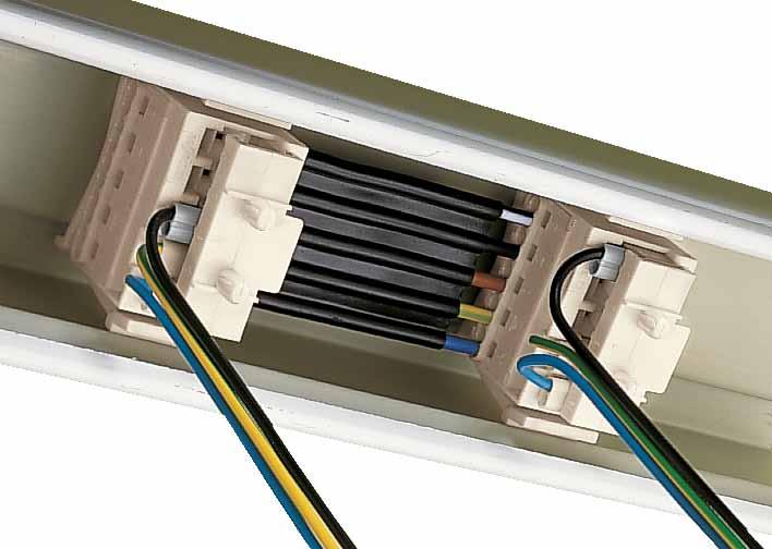
5 2 Connector System with Phase Selection for Fluorescent Lighting Fixtures Conductor Supports 267 Series 267 Series for Partially Stripped Conductors Contact-free conductor support Compact design 267 Series with Insulation Displacement Connection (IDC) Flexible, modular 5- to 11-pole connector system IDC connection for through-wiring applications Scalable future system expansions also possible Technical data: PUSH WIRE connection PUSH WIRE connection IDC connection Connector for in-line mounting of fluorescent lighting fixtures and snap-on type conductor support Female connector Conductor support Rating per IEC/EN 6198 IEC/EN 6198 IEC/EN 6198 Overvoltage category II II II Pollution degree Rated voltage 500 V 500 V 500 V Rated surge voltage kv kv kv Nominal current 16 A 6 A 6 A Approvals per UL 1977 UL 1977 UL 1977 Rated voltage 600 V 600 V 600 V Nominal current UL 15 A 6 A 6 A Material data: Material group I Insulating material Polyamide 6.6 (PA 6.6) Temperature stability 105 C Flammability rating per UL 9 V0 Clamping spring material Chrome nickel spring steel (CrNi) Contact material Electrolytic copper (E Cu ) Contact plating tin-plated Approvals are available online at:

6 Connection System with Phase Selection for Fluorescent Lighting Fixtures Conductor Supports Partially Stripped Conductors 25 With snap-on foot With dovetail With custom foot 5 x mm 2 sol. 5 x AWG 16 1 sol. 5 x mm 2 sol. 5 x AWG 16 1 sol. 5 x mm 2 sol. 5 x AWG 16 1 sol. 500 V/ kv/2 6 A 600 V/6 A 500 V/ kv/2 6 A 600 V/6 A 500 V/ kv/2 6 A 600 V/6 A Pole No. Pole Marking Item No. Conductor support with snap-on foot, consisting of base and cover, with molded pole marking on cover, white Pack. Unit Pole No. Pole Marking Item No. Conductor support with dovetail, consisting of base and cover, with molded pole marking on cover, white Pack. Unit Pole No. Pole Marking Item No. Conductor support with custom foot, consisting of base and cover, with molded pole marking on cover, white Pack. Unit Cover Cover Cover 5 N N N Base Base Base acc. to customer specifications < 1 > 7,5 < 32 > < 30 > N < 30 > < 32 > 1,9 <11,8 > 7,3 7 > < < 21 > 5 < 29,8 > 7, 1,8 1,6 < 2 > N max. 19 min. 16


7 26 Connection System with Phase Selection for Fluorescent Lighting Fixtures, Female Connectors Partially Stripped Conductors $ With PUSH WIRE connection for ground With direct ground contact conductors mm 2 sol. AWG sol mm 2 sol. AWG sol. 500 V/ kv/2 6 A 600 V/6 A 500 V/ kv/2 6 A 600 V/6 A l 8 mm / 0.31 in l 8 mm / 0.31 in Pole No. Item No. Pack. Unit Pole No. Item No. Pack. Unit Female connector with snap-in mounting feet and PUSH WIRE connection for ground conductors, white /gray, with molded pole marking, gray female connector for phase selection to (not possible with 5-pole female connectors) Female connector with snap-in mounting feet and direct ground contact, white /gray, with molded pole marking, gray female connector for phase selection to (not possible with 5-pole female connectors) < 10 > < 3 > 5 < 10 > < 10 > < 20 > Plate thickness: mm Plate thickness: mm Conductor support < 32 > 3 2 N 3 1 < 26 > Conductor support 3 2 N 3 1 < 10 > < 32 > 1 Diameter of drilled hole:.2 mm 2 Diameter of drilled hole: 5.2 mm 1 Diameter of drilled hole:.2 mm 2 Diameter of drilled hole: 5.2 mm Drilled hole for direct ground contact must be free of varnish and oxide films. Equipped with varnished metal plates upon request. Approvals are available online at:

8 Connector System with Phase Selection for Fluorescent Lighting Fixtures, Conductor Supports with Power Supply Connections With direct ground contact 5 x 2/ mm 2 sol. 5 x AWG 16 1 sol. 5 x 2/ mm 2 sol. 5 x AWG 16 1 sol. 500 V/ kv/2 6 A 600 V/6 A 500 V/ kv/2 6 A 600 V/6 A l mm / 0.5 in l mm / 0.5 in $ 27 Pole Pole Marking Item No. Pack. Unit No. Conductor support with power supply connection and snap-in mounting feet, white Pole Pole Marking Item No. Pack. Unit No. Conductor support with power supply connection and snap-in mounting feet, with direct ground contact, white 3 N PE N PE N PE N PE N PE N PE <_ 10 _> < 36,1 > 5 1 < 17,1 > _> < N 3 <_ 10 _> > 5,2 < 3 3 < 19 > > < 39, N Custom foot adjustment < 23,1 > < 15 > < 12 ><_8_> Plate thickness: mm <7,5> 3 Diameter of drilled hole:.2 mm Diameter of drilled hole: 5.2 mm Drilled hole for direct ground contact must be free of varnish and oxide films. Equipped with varnished metal plates upon request.


,8 5,2 (_ Conductor support with IDC contacts < 69,5 > < 2,3 > < 10 > < 30 > < 2 > D C B A Snap-on type conductor")
9 _) _) 28 Connection System with Phase Selection for Fluorescent Lighting Fixtures, Conductor Supports with Insulation Displacement Connection (IDC) % With dovetail guide and IDC contacts With direct ground contact Snap-on type conductor support mm 2 sol. AWG 16 1 sol mm 2 sol. AWG 16 1 sol. 500 V/ kv/2 16 A 600 V/15 A 500 V/ kv/2 6 A 600 V/6 A 500 V/ kv/2 6 A 600 V/6 A l mm / 0.5 in Pole No. Conductor support cover, with dovetail guide and IDC contacts, with molded pole marking, white Pole Marking Item No. Pack. Unit Item No. Pack. Unit Color Item No. Pack. Unit Conductor support base with snap-in mounting feet, white Snap-on type conductor support, -pole without snap-in ground contact 5 N mm 2 7 N Cover, white with snap-in ground contact mm Cover, gray < 23 >( 12,9 ) 1 3 N < 30 > Cover in pre-locked position > 8 _) 1 6 > < 2 > 2,1 > < < 50 > Custom foot adjustment <_ 21,5 > < 25,9 > <_ 15,5 _> _),8 5,2 (_ Conductor support with IDC contacts < 69,5 > < 2,3 > < 10 > < 30 > < 2 > D C B A Snap-on type conductor support 1 Diameter of drilled hole:.2 mm 2 Diameter of drilled hole: 5.2 mm Approvals are available online at:

10 Connection System with Phase Selection for Fluorescent Lighting Fixtures, Female Connectors for Conductor Supports with Insulation Displacement Connection (IDC) with PUSH WIRE connection for ground conductors and strain relief plate With PUSH WIRE connection for ground conductors $ With direct ground contact mm 2 sol. AWG sol mm 2 sol. AWG sol mm 2 sol. AWG sol. 500 V/ kv/2 6 A 600 V/6 A 500 V/ kv/2 6 A 600 V/6 A 500 V/ kv/2 6 A 600 V/6 A l 8 mm / 0.31 in l 8 mm / 0.31 in l 8 mm / 0.31 in 29 Pole No. Item No. Pack. Unit Pole No. Item No. Pack. Unit Pole No. Item No. Pack. Unit Female connector with PUSH WIRE connection for ground conductors and strain relief plate, white/gray Female connector with snap-in mounting feet and PUSH WIRE connection for ground conductors, white /gray, with molded pole marking, gray female connector for phase selection to 1, 2, 3, +, (not possible with 7-pole female connectors) Female connector with snap-in mounting feet and direct ground contact, white /gray, with molded pole marking, gray female connector for phase selection to 1, 2, 3, +, (not possible with 7-pole female connectors) < 20 > <_ 15_> < 20 > <_ 15_> <_15 _> (_10_) <6> < 20 > < 15 > (_10 _) < 20 > > 5 < (_10_) Plate thickness: mm < 55 > <_ 15 _> (_10_) < 3 > 5 < (_10_) (_10_) (_10_) < 20 > < 20 > Plate thickness: mm Plate thickness: mm N <_ 15 _> (_10_) < 3 > 5 < N (_10_) < 3 > Conductor support Conductor support < 32 > > 5 (_10 _) < 26 > (_10_) <_ 15_> < 2 > < 26 > Conductor support < 32 > > 5 (_10 _) < 26 > (_10_) <_ 15_> < 2 > < 26 > 1 Diameter of drilled hole:.2 mm 2 Diameter of drilled hole: 5.2 mm 1 Diameter of drilled hole:.2 mm 2 Diameter of drilled hole: 5.2 mm Drilled hole for direct ground contact must be free of varnish and oxide films. Equipped with varnished metal plates upon request.

11 250 Connection System with Phase Selection for Fluorescent Lighting Fixtures, Female Connectors/Female Modules for Conductor Supports with Insulation Displacement Connection (IDC) $ Snap-on type female connector Female module mm 2 sol. AWG 16 1 sol. 2 x mm 2 sol. AWG 16 1 sol. 500 V/ kv/2 16 A 600 V/6 A 500 V/ kv/2 16 A 600 V/6 A l 8 mm / 0.31 in l 8 mm / 0.31 in Pole No. Item No. Pack. Unit Color Item No. Pack. Unit Snap-on type female connector Female module, 1-pole black gray red yellow purple Snap-on type conductor support Female module < 33,3 > ( 15,5 ) < 3 > < 16,8 > A B C D _) 5,8 (_ Female connector > (3,1) < 6,8 > 2,35 < < 26,9 > < 10 > < 21,5 > < 3,3 > Approvals are available online at:
12 < < < < < Connectors for In-Line Mounting of Fluorescent Lighting Fixtures $ 251 Without ground contact tab With ground contact tab With ground contact tab mm 2 sol. AWG 16 1 sol mm 2 sol. AWG 16 1 sol. 2 x mm 2 sol. AWG 16 1 sol mm 2 sol. AWG sol. 500 V/ kv/2 16 A 600 V/15 A 500 V/ kv/2 16 A 600 V/15 A 500 V/ kv/2 16 A 600 V/15 A l mm / 0.5 in l mm / 0.5 in l mm / 0.5 in Pole Pole Marking No. Female connector, white Item No. Pack. Unit Pole Pole Marking Item No. No. Male connector with connection for ground contact tab, white Pack. Unit Pole Pole Marking Item No. No. Male connector with connection for ground contact tab, white 7 N N N N N * 50 5 N Pack. Unit Female connector, gray Male connector with connection for ground contact tab, gray A B C D A B C D * 50 Female connector, yellow Male connector with connection for ground contact tab, yellow 1,5-2,5 mm > 2 0,75-1,5 mm > 2 A B C D A B C D * 50 *Enhanced locking strength If the power for the 3-phase circuit is supplied via the male connector's termination side, current may only be supplied within one individual lighting fixture, or one continuous row of luminaires. Female connector < 53,1 > Male connector < 39 > < 35,6 > 1 _> < 18 > Custom foot adjustment < 36,6 > < 3 > _ N < 35 > N 3 + _ < 36,6 > > 3,5< > 5,5 < 20 > 30 Ground contact tab 3 < 3 < <_10 _> 0,8 < 5,5 < > Additional approvals and corresponding ratings can be found at


13 $ Description and Handling Connection System with Phase Selection for Fluorescent Lighting 252 Fixtures, 277 Series Inserting solid conductor via push-in termination. Removing conductor. Selecting a phase via movable phase contacts. 277 Series Phase selection Equal load on each phase via phase selection. Connecting a lighting fixture Connecting a lighting fixture equipped with a fixed female connector. Dimensions refer to a mated assembly Marking < 38.5 mm/1.516 in > < 0.5 mm/1.59 in > Female connector without mounting adapter. Male connector with snap-in mounting feet. Female connector without mounting adapter. Male connector with strain relief. Molded pole marking. PUSH WIRE clamps the following copper conductors: solid
14 253
15 25 Connection System with Phase Selection for Fluorescent Lighting Fixtures 277 Series Flexible connection system equipped with PUSH WIRE connection Phase selection Technical data: Female connector Male connector Rating per IEC/EN 6198 IEC/EN 6198 Overvoltage category II II Pollution degree 2 2 Rated voltage 00 V 00 V Rated surge voltage kv kv Nominal current 16 A 10 A Approvals per UL 1977 UL 1977 Rated voltage 600 V 600 V Nominal current UL 7 A 7 A Material data: Material group I Insulating material Polyamide 6.6 (PA 6.6) Temperature stability 105 C Flammability rating per UL 9 V0 Clamping spring material Chrome nickel spring steel (CrNi) Contact material Electrolytic copper (E Cu ) Contact plating tin-plated Approvals are available online at:


 Female connector, white, with molded pole marking 3 277-123 500 3 277-126 250 without")
16 Connection System with Phase Selection for Fluorescent Lighting Fixtures, Male and Female Connectors $ 255 Male connectors with snap-in mounting feet Male connectors with strain relief Female connectors with/without mounting adapter 0.5 x 1.0 mm 2 sol. AWG sol. 0.5 x 1.0 mm 2 sol. AWG sol. 5 x mm 2 sol. 5 x AWG 16 1 sol. 00 V/ kv/2 10 A 600 V/7 A 00 V/ kv/2 10 A 600 V/7 A 00 V/ kv/2 16 A 600 V/7 A l mm / 0.1 in l mm / 0.1 in l mm / 0.5 in Pole No. Item No. Pack. Unit Pole No. Item No. Pack. Unit Pole No. Item No. Pack. Unit Male connector with snap-in mounting feet, white/ gray, with molded pole marking, gray, movable phase selection contacts (not for 5-pole male connector) Male connector with strain relief, white/gray, with molded pole marking, gray, movable phase selection contacts (not for 5-pole male connector) Female connector, white, with molded pole marking without mounting adapter with mounting adapter < 15 ±0,05 > > 5,2 +0,1 < max. 1 mm thick Wiring example: Equal load on each phase via phase selection on male connector, without altering existing wiring. < 37 > N < 25 > ( 6,7 ) < 35, > < 30,8 > > 7,3 < < 22 > < 5 > > 7 < > 9 < < 0 > < 0 > L3 L2 L1 3 N < 30 > < 31, >


17 256 Description and Handling Fully Polarized Connectors for Lighting Fixtures with Push-Wire Connection Push-wire connection Connection of conductors: Push conductor in FIRMLY until FULLY inserted! Removal of conductor Clamping of 2 conductors, each conductor is clamped independently Strain relief Strain relief with cable clamp Application Lighting fixture ready for connection with center receptacles (internal wiring complete with WAGO terminal blocks) Supply Plugging Marking Supply of lighting fixture by pushing the female connector onto the center receptacle Plugging in the female connector with connecting lead to the next lighting fixture Series marking of poles PUSH WIRE clamps the following copper conductors: solid


18 Strain relief Connection of 2 lighting fixtures Application 257 Male connector with complete strain relief device Mating of connecting cables of two lighting fixtures Lighting fixture ready for connection Application Ceiling or flushmount distribution Coding Series marking of poles Connector with additional coding pins/holes
, 6 A (connection to the lighting fixture) l 8 9 mm / 0.")
19 258 Fully Polarized Connectors for Lighting Fixtures in Dropped Ceilings 2 x mm 2 s 2 x AWG 20 1 sol. 200 V/ kv/ V/ kv/ A l 8 9 mm / 0.33 in 1 x 0.5/0.75 mm 2 s 1 x AWG sol. 200 V/ kv/ V/ kv/ A (through connection), 6 A (connection to the lighting fixture) l 8 9 mm / 0.33 in 1 In grounded (earthed) supply systems 200/00 V = rated voltage kv = rated surge voltage 2/3 = pollution degree (see also section 10) 2 Suitable for assembly without tool 3 or of a cable NYM 3 x 2.5 mm 2 /5 x 2.5 mm 2 (AWG 1) Description Fully polarized connectors for lighting fixtures in dropped ceilings, for screw or screwless fixing (WAGO pins), with standard printing, push-in type strain relief devices, coding mask of center receptacle and female connectors with integrated locking device. Accessories Strain relief support, with clamp for 2 cables NYM max. Strain relief housing, for 2 cables NYM max. Pins, for plate thickness 3-pole 5-pole 3-pole 5-pole Pin 0.5/0.75 mm 2 terminals, 1/1.5 mm 2 insulated 2.5 mm 2 Crimping tool, for pin terminals, crimping range mm 2 /AWG 20 1 No. of Poles Item No. Pack. Unit Male connector, with preceding earth contact, white / Ditto, with additional coding pins (poles 3 and 1), white / / x 1.5 mm x 1.5 mm x 1.5 mm x 1.5 mm I N 6/8 A, green I N 10/16 A, beige I N 20 A, blue No. of Poles Item No. Pack. Unit Center receptacle, with coding mask, white/gray / Ditto, with additional coding pins and holes (poles 3 and 1), white /grey / / mm /0.039 in mm /0.039 in mm /0.059 in A fully polarized 3-pole connector for lighting fixtures in dropped ceilings is consisting of the following element: Female connector for reverse mounting / Strain relief housing Strain relief support Strain relief housing mm 2 Strain relief support Male connector / Center receptacle / Dimensions (in mm) No. Dimension L (mm) of Poles Male Center Female connector receptacle connector Overall length of the connectors in mated condition: 12 mm /5.591 in (incl. strain relief device) > 15,3 < < L > > 10 < 1,1 <_ < 23,3 > < 3 > > <15,3 > < 1,65 > < L > > <_ 1,1 < 6,15 > * For further approvals with corresponding ratings see pages 500 to 503.
20 259 2 x mm 2 s 2 x AWG 20 1 sol. 200 V/ kv/ V/ kv/ V, 10 A U 16 A l 8 9 mm / 0.33 in No. of Poles Item No. Pack. Unit Female connector for reverse mounting, with coding mask, white /grey / Ditto, with additional coding holes (poles 3 and 1) / / Chamfer < Ø 3,2 > 3 x 1.5 mm x 1.5 mm x 1.5 mm Dimensions of fixing holes for pins 5 x 1.5 mm I N 6/8 A, green I N 10/16 A, beige I N 20 A, blue Fixing pin from top > <_ 2 Screwless fixing with pins ,5 < Fixing pin from below <_ 23,8 _> < 35,2 > > > <_ 3 > 2,9 < Fixing pin from top Fixing pin from below Screwless fixing with pins or < 20 > < L > Connector with additional coding pins/holes

21 260 Fully Polarized Connectors for Lighting Fixtures 2 x mm 2 s 2 x AWG 20 1 sol. 200 V/ kv/ V, 10 A U 00 V/ kv/ V, 10 A 2 16 A l 8 9 mm / 0.33 in 2 x mm 2 s 2 x AWG 20 1 sol. 200 V/ kv/ V, 10 A U 00 V/ kv/ V, 10 A 2 16 A l 8 9 mm / 0.33 in 1 In grounded (earthed) supply systems 200/00 V = rated voltage kv = rated surge voltage 2/3 = pollution degree (see also section 10) 2 If 2 cables NYM are connected at the same time only up to 0.75 mm 2 s /AWG 18 solid! 3 Suitable for mounting without tool Description Fully polarized connectors for lighting fixtures, for screw or screwless fixing (WAGO pins), with standard printing, push-in type strain relief devices, coding mask of female connectors with integrated locking device. Accessories Strain relief support, with clamp for 2 cables NYM max. Strain relief housing, for 2 cables NYM max. Strain relief housing, for single insulated conductors Pins, for plate thickness 2-pole 3-pole -pole 5-pole 2-pole 3-pole -pole 5-pole 3-pole 5-pole Pin 0.5/0.75 mm 2 terminals, 1/1.5 mm 2 insulated 2.5 mm 2 Crimping tool, for pin terminals, crimping range mm 2 /AWG 20 1 No. of Poles Item No. Pack. Unit Male connector, white Male connector, with preceding earth contact, white / / with coding pins / x 1.5 mm x 1.5 mm x 1.5 mm x 1.5 mm x 1.5 mm x 1.5 mm x 1.5 mm x 1.5 mm up to 6 x 2.5 mm up to 10 x 2.5 mm mm/0.039 in mm/0.039 in mm/0.059 in I N 6/8 A, green I N 10/16 A, beige I N 20 A, blue No. of Poles Item No. Pack. Unit Female connector, with coding mask, white/gray / / / Same, with additional coding holes / x 1.5 mm x 1.5 mm x 1.5 mm x 1.5 mm x 1.5 mm x 1.5 mm x 1.5 mm x 1.5 mm up to 6 x 2.5 mm up to 10 x 2.5 mm mm/0.039 in mm/0.039 in mm/0.059 in I N 6/8 A, green I N 10/16 A, beige I N 20 A, blue A fully polarized 3-pole connector is consisting of the following elements: Female connector / Strain relief housing Strain relief housing Strain relief support < 58 mm** > (2.283 in) Strain relief support Male connector / Dimensions (in mm) No. Dimension L (mm) Dimension L (mm) of Poles Male connector Female connector ** Overall length of the connectors in mated condition: 117 mm /.606 in (incl. strain relief devices) > 15,3 < < L > > 10 < 1,1 <_ < 23,3 > < 3 > > <15,3 > < 1,65 > < L > > <_ 1,1 < 6,15 > * For further approvals with corresponding ratings see pages 500 to 503.
22 261
23 $ Luminaire Disconnect Connectors (US Version) 873 Series conductor plug 1 AWG s AWG st 1-conductor socket 2 AWG 18 s 600 V, 6 A2 2-conductor plug 1 AWG s AWG st 1-conductor socket 2 AWG 18 s 600 V, 6 A2 L mm / 0.7 in 1 l 9 11 mm / 0.39 in 2 L mm / 0.7 in 1 l 9 11 mm / 0.39 in 2 Kein Produktbild!! Kein Produktbild!! 1 2-conductor plug 2 1-conductor socket Pack. Pole No. Item No. Unit Luminaire disconnect connector Pack. Pole No. Item No. Unit Luminaire disconnect connector Touchproof connectors are required for ballast supply cables in the USA and Canada. When exchanging a ballast: 1. The touchproof plug-in connection is disconnected first 2. The ballast is replaced 3. Network connection is restored by plugging the connection. This streamlines ballast replacement while enhancing safety by safeguarding the installer from electric shock. The 873 Series connectors are approved according to UL 259 and CSA 22.2 for this type of application. 0,75 mm 2 1,5 mm AWG CU, SOL, UL/CSA AWG ( 19 str.) CU, UL 1 12 AWG ( 19 str.) CU, CSA One-time use only Do not reuse N utiliser qu une seule fois 0,75 mm 2 18 AWG CU, SOL, UL/CSA The 873 Series is also approved to EN and EN 6198 as follows: EN mm² solid, 6A for female part 1.5 mm² mm² solid, 32A for male part 00 V/ kv/2 EN mm² solid, 6A for female part 0.75 mm² mm² solid, 32A for male part 00 V/ kv/2 0.5 inch / mm 0.35 inch / 9 11 mm Correct method of solid wire removal Hold wire to be removed in one hand, the connector in the other twist slightly while pulling the connector. Déconnexion correcte du conducteur rigide Tenir d une main le conducteur à déconnecter et de l autre main le connecteur Opérer une légère torsion du conducteur tout en tirant sur le connecteur. Approvals are available online at:
24 Luminaire Disconnect Connectors (US Version) 873 Series 2-conductor plug 1 1-conductor socket 2 AWG s AWG 18 s AWG st L mm / 0.7 in 1 l 9 11 mm / 0.39 in 2 $ 263 Kein Produktbild!! Pack. Pole No. Item No. Unit Luminaire disconnect connector, preceding ground contact in center position conductor plug 2 1-conductor socket Touchproof connectors are required for ballast supply cables in the USA and Canada. When exchanging a ballast: 1. The touchproof plug-in connection is disconnected first 2. The ballast is replaced 3. Network connection is restored by plugging the connection. This streamlines ballast replacement while enhancing safety by safeguarding the installer from electric shock. The 873 Series connectors are approved according to UL 259 and CSA 22.2 for this type of application. 0,75 mm 2 1,5 mm AWG CU, SOL, UL/CSA AWG ( 19 str.) CU, UL 1 12 AWG ( 19 str.) CU, CSA One-time use only Do not reuse N utiliser qu une seule fois 0,75 mm 2 18 AWG CU, SOL, UL/CSA The 873 Series is also approved to EN and EN 6198 as follows: EN mm² solid, 6A for female part 1.5 mm² mm² solid, 32A for male part 00 V/ kv/2 EN mm² solid, 6A for female part 0.75 mm² mm² solid, 32A for male part 00 V/ kv/2 0.5 inch / mm 0.35 inch / 9 11 mm Correct method of solid wire removal Hold wire to be removed in one hand, the connector in the other twist slightly while pulling the connector. Déconnexion correcte du conducteur rigide Tenir d une main le conducteur à déconnecter et de l autre main le connecteur Opérer une légère torsion du conducteur tout en tirant sur le connecteur.
Technical data: Pin Spacing
 282 Female Connectors, Double-Row Pin Spacing: 3.5 mm Universal connection for all conductor types Unique, compact, double-row connector system for conductor cross sections up to 1.5 mm 2 High-density,
Item No.: /
 mounting adapter also for DIN 35 rail; % protected against mismating; Plate thickness 06x12 mm; Male connector; with snap-in mounting foot; 4-pole; pin spacing 35 mm / 0138 in; with 209-137 mounting adapter
Electrical Interconnection
 Electrical Interconnection Edition 208/ Rail-Mount Terminal Block Systems Full Line Catalog, Volume Edition 207/208 PCB Terminal Blocks and Connectors Full Line Catalog, Volume 2 Edition 207/208 2 Automation
Item No.: /
 Angled female connector; with snap-in mounting foot; 3-pole; pin spacing 5 mm / 097 in; 00% protected against mismating; for panel mounting; Plate thickness 06x2 mm; Fixing holes 35 mm Ø Item Angled female
Male connector; 6-pole; pin spacing 3.5 mm / in; 100% protected against mismating
 Male connector; 6-pole; pin spacing 35 mm / 0138 in; % protected against mismating Item Male connector; 6-pole; pin spacing 35 mm / 0138 in; % protected against mismating Marking Business data Supplier
Modular Terminal Blocks and Terminal Strips with CAGE CLAMP, Series 260 to 262, Side-Entry
 36 Modular Terminal Blocks and Terminal Strips with CAGE CLAMP, Series 260 to 262, Side-Entry Assembly Assembly of modular terminal blocks to terminal strips Mounting of an end plate screw fixing CAGE
1-Conductor Female Connector with Levers Pin Spacing: mm MCS MAXI 16
 -Conductor Female Connector with evers Pin Spacing: 0.6 mm MCS MAXI 6 Intuitive and tool-free lever actuation Universal connection for all conductor types Push-in termination of solid or ferruled conductors
Male connector; with fixing flanges; 6-pole; pin spacing 5.08 mm / 0.2 in; for screw or similar mounting types; for parallel or perpendicular mounting
 Male connector; with fixing flanges; 6-pole; pin spacing 508 mm / 02 in; for screw or similar mounting types; for parallel or perpendicular mounting Item No: 231-636/019-000 Male connector; with fixing
Electrical Interconnections. Supplementary Catalog to Full Line Catalogs, Volumes 1/2/5 Edition 2012/2 1/2/5
 Electrical Interconnections Supplementary Catalog to Full Line Catalogs, Volumes /2/ Edition 202/2 /2/ The new items in this catalog supplement products found in the following main catalogs /2/ Volume
Female connector; 2-pole; pin spacing 5 mm / in; codable; only 1 locking latch; with coding finger; with latch
 Female connector; 2-pole; pin spacing 5 mm / 097 in; codable; only locking latch; with coding finger; with latch Item No: 23-02/026-000 Female connector; 2-pole; pin spacing 5 mm / 097 in; codable; only
Modular PCB terminal block; 2 solder pins/pole; 1-pole; pin spacing 5/5.08 mm / 0.2 in; with push-button
 push-button - Item No: 255-40 Modular PCB terminal block; 2 solder pins/pole; -pole; pin spacing 5/508 mm / 02 in; with push-button Item No: 255-40 Modular PCB terminal block; 2 solder pins/pole; -pole;
for a perfect electrical installation. The range of rail-mounted terminal blocks
 The range of rail-mounted terminal blocks for a perfect electrical installation. The range of rail-mounted terminal blocks for a perfect electrical installation. The new standard for rail-mounted terminal
TOPJOB S Sensor/Actuator Terminal Blocks Pluggable Signal Level with Push-in CAGE CLAMP Reliability
 TOPJOB S Sensor/Actuator Terminal Blocks Pluggable Signal Level with Push-in CAGE CLAMP Reliability TOPJOB S SEND THE RIGHT SIGNALS For the very first time, sensor/actuator wiring is pluggable between
WINSTA. Full Line Catalog 2008/2009
 WINSTA Full Line Catalog 2008/2009 5 Contents FULL LINE CATALOG W4, Volume 1 Rail-Mounted Terminal Block Systems FULL LINE CATALOG W4 Rail-Mounted Terminal Blocks Volume 1 X-COM -SYSTEM Terminal Strips
TOPJOB S Sensor/Actuator Terminal Blocks with Push-in CAGE CLAMP Reliability
 TOPJOB S Sensor/Actuator Terminal Blocks with Push-in CAGE CLAMP Reliability TOPJOB S SEND THE RIGHT SIGNALS. TOPJOB S Sensor/Actuator Terminal Blocks with Push-in CAGE CLAMP Reliability TWO IN ONE. WITH
SMD PCB TERMINAL BLOCKS We Connect Your Lights
 SMD PCB TERMINAL BLOCKS We Connect Your Lights SMD PCB TERMINAL BLOCKS A compact and low-profile PCB connection is required for optimal uniform light distribution, while minimizing shadowing. WAGO s SMD
8WH5 Combination Plug-In Terminals
 8WH Combination Plug-In Terminals /2 Introduction / 8WH through-type terminals 1) /7 8WH hybrid through-type terminals with ipo connection /8 8WH9 plugs 1) 1) Also available as a PE version More technical
Item No.: /
 Female connector; with angled solder pins; 4-pole; with locking levers; pin spacing 508 mm / 02 in; solder pin 06x mm; codable; Horizontal PCB mounting Item No: 232-264/039-000 Female connector; with angled
SMD PCB Terminal Blocks We Connect Your Light
 SMD PCB Terminal Blocks We Connect Your Light SMD PCB TERMINAL BLOCKS A compact and low-profile PCB connection is required for optimal uniform light distribution, that minimizes shadowing. WAGO s SMD PCB
07. har-link INTERFACE CONNECTORS
 . INTERFACE CONNECTORS The highest data rates in combination with perfect shielding characterize the connector. This way data can be passed on optimally within the control cabinet. The locking mechanism
Through-Board SMD PCB Terminal Block; 0.75 mm² Pin Spacing: 6.5 mm 2070 Series
 Volume, Section SMD PCB Terminal Blocks Through-Board SMD PCB Terminal Block; 0.75 mm² 070 Series SMD PCB terminal blocks with Push-in CAGE CLAMP connection for back-side wiring of LED modules Low profile
Han PCB termination. Han-Fast Lock PCB adapter for Han DD PCB adapter for Han DDD module
 Han termination Contents Page Han-Fast Lock... 20.11 adapter for Han DD... 20.13 adapter for Han DDD module... 20.16 adapter for Han 40 A Axial module... 20.18 adapter for Han E... 20.20 adapter for Han
07. har-link Interface Connectors
 . Interface Connectors The highest data rates in combination with perfect shielding characterize the connector. This way data can be passed on optimally within the control cabinet. The locking mechanism
Applications
 Han PCB adapter Contents Page Technical characteristics PCB adapter for Han DD... 20.02 Han DD Inserts with PCB adapter... 20.03 Technical characteristics PCB adapter for Han E... 20.04 Han E Inserts with
SMD PCB TERMINAL BLOCKS We Connect Your Lights
 SMD PCB TERMINAL BLOCKS We Connect Your Lights SMD PCB TERMINAL BLOCKS A compact and low-profile PCB connection is required for optimal uniform light distribution, while minimizing shadowing. WAGO s SMD
07. har-link Interface Connectors
 . Interface Connectors The highest data rates in combination with perfect shielding characterize the connector. This way data can be passed on optimally within the control cabinet. The locking mechanism
SMD Terminal Blocks Small is Big
 SMD Terminal Blocks Small is Big SMD Terminal Blocks A compact and flat printed circuit board connection is required to achieve the most uniform light distribution, while minimizing shadowing. WAGO s SMD
Industrial Ethernet Panel-Mount Adaptors for PROFINET or EtherNet/IP Applications
 Industrial Ethernet Panel-Mount Adaptors for PROFINET or EtherNet/IP Applications Type 0981 ENC 100 RJ45/M12 adaptor, female receptacle connector M12, D coding, chassis side thread PG 9, RJ45 female connector,
Details of the Han-Terminal block connector Han D AV Han D AV Distributor Han E AV Han ES AV
 Contents -Terminal Block Connectors Page Details of the -Terminal block connector........................ 08.02 D................................................... 08.10 D Distributor...........................................
Surface Mount Terminal Blocks with Push-Buttons
 Surface Mount Terminal Blocks with Push-Buttons Surface Mount Terminal Blocks with Push-Buttons Pin Spacing 4 mm, 8 mm 2060 Series Surface mount terminal blocks with CAGE CLAMP S connection and push-buttons
Male header, 100% protected against mismating, (1 x 1) mm straight solder pins Pin spacing 3.5 mm 3.81 mm. light gray <_ 8,5_> 3,5 1x1 <_ 9,3_>
 mm straight solder pins Pin spacing 3.5 mm 3.81 mm. light gray <_ 8,5_> 3,5 1x1 <_ 9,3_>") 96 Male Headers with Solder Pins; Double-Deck Male Headers with Solder Pins, Pin Spacing 3.5 mm and 3.81 mm 160 V/.5 kv/ 300 V, 10 A U 10 A 300 V, 10 A 160 V/.5 kv/ 300 V, 10 A U 10 A 300 V, 10 A 160 V/.5
96 Male Headers with Solder Pins; Double-Deck Male Headers with Solder Pins, Pin Spacing 3.5 mm and 3.81 mm 160 V/.5 kv/ 300 V, 10 A U 10 A 300 V, 10 A 160 V/.5 kv/ 300 V, 10 A U 10 A 300 V, 10 A 160 V/.5
Electrical Connection Technology. New Items: Autumn 2007
 Electrical Connection Technology New s: Autumn 2007 Contents Rail-Mounted Terminal Block Systems Volume 1 02 57 PCB Terminal Blocks and Connectors Volume 2 58 91 WINSTA WINSTA 93 97 Index of Nos. 98 102
Han-Brid. Contents Han-Brid Features Han-Brid Data interfaces Han-Brid Overview Han-Brid Cu
 Contents Page Features... 19.02 Data interfaces... 19.03 Overview... 19.04 Cu... 19.06 F.O.... 19.08 Quintax 3 A... 19.10 RJ45 C... 19.12 USB / FireWire... 19.14 Han 4 A SC... 19.16 Hoods/Housings... 19.18
- 1 - General ordering data Order No
 General ordering data Order No. 1730710000 Part designation BL 5.00/3 SN SW Version EAN 4008190387327 Qty. 100 pc(s). System parameters Conductor connection system Leaf spring connection Outgoing direction
ODU MINI-SNAP PC Product Description. ODU MINI-SNAP PC: The Connector with Push-Pull-Locking in Plastic
 ODU MINI-SNAP PC Product Description ODU MINI-SNAP PC: The Connector with Push-Pull-Locking in Plastic Cylindrical Connectors are generally available with several locking mechanisms: The most frequently
RECTANGULAR POWER CONNECTORS
 TE Connectivity: Every Connection Counts 2015 TE Connectivity Ltd. family of companies. All Rights Reserved TE CONNECTIVITY (TE) 08P MTA156 CONN ASSY 3-643818-8 TE Internal Number: 3-643818-8 Product Type
Data sheet... OMNIMATE Power - series BL/SL 7.62HP BLZ 7.62HP/04/180LR SN BK BX
 Power on board #96 100% safety, 100% integration, 100% cost-effectiveness: The compact and efficient solution for UL-600V applications in the lower performance range (up to 12 kva). 29 A at 400V (IEC)
Slim Relay G2RV. Model Number Structure. Ordering Information. Model Number Legend. List of Models. Relay and Socket Combinations
 Slim Relay G2RV The World's First Industrial Slim Relay Large plug-in terminals for reliable connection. LED indicator and mechanical flag to check operation. Transparent housing enables checking relay
M12 connector D-coding M12 connector X-coding RJ45 IP20 connector PushPull RJ45 IP65 / IP67 connector
 M12 connectors Directory Chapter Page General information....02 M12 connector D-coding....06 M12 connector X-coding....20 RJ45 IP20 connector....27 PushPull RJ45 IP65 / IP67 connector....46 Han 3 A RJ45
M12 Field Wireable Connectors. M12 CAT.6A Field Wireable Connectors. M12 Field Wireable Connectors for PROFINET
 M12 Connectors Application Advantage Shielded design ETHERLINE Ethernet Cable, Connectors & Tools M12 Field Wireable Connectors Male Female Temperature Range: Max. 85 C Nominal Voltage: Nominal Current:
revos revos Industrial Multipole Connectors 3 48 pole in metal housing Program for Tough Tasks
 revos Industrial Multipole Connectors 3 8 pole in metal housing Program for Tough Tasks Heavyduty industrial plug connectors for all applications The heavyduty industrial plug connectors revos are classified
Transparent Covers for Rail-Mounted Terminal Blocks, Usable with Lead Seals Description and Handling
 Transparent Covers for Rail-Mounted Terminal Blocks, Usable with Lead Seals Description and Handling 572 Assembly Application Snapping a cover carrier onto the carrier rail. Application examples: cover
Classification Enclosure rating Input voltage Type of
 Slim Relay G2RV The World's First Industrial Slim Relay Large plug-in terminals for reliable connection. LED indicator and mechanical flag to check operation. Special input type with gold plated contacts.
JAN 16 Rev B
 ANSI C136.41-2013 Rotatable Dimming Receptacles Application Specification 20 JAN 16 Rev B NOTE All numerical values are in metric units [with U.S. customary units in brackets]. Dimensions are in millimeters
ME PLC Multifunctional housing for complex electronics. Data sheet _en_01. 1 Description
 Multifunctional housing for complex electronics Data sheet 105504_en_01 PHOENIX CONTACT 2013-04-08 1 Description The housings of the ME PLC 40... product group consist of a 40-mm wide housing base with
Positive Mate Connection System
 Introduction High Current Flow with Low Insertion Force Product Features All Positive Mate housings include a secondary contact retention feature Polarization is provided Rounded corners on housings prevent
UK 5-MTK-P/P. Extract from the online catalog. Order No.:
 Extract from the online catalog UK 5-MTK-P/P Order No.: 3004032 Disconnect and test disconnect terminal block, Connection type: Screw connection, Cross section: 0.2 mm² - 6 mm², AWG: 24-10, Nominal current:
Extract from the online catalog
 Please note that the data given here has been taken from the online catalog. For comprehensive information and data, please refer to the user documentation at http://www.download.phoenixcontact.com. The
Description of parts Panel mounting Insert mounting without/with Carrier element Plastic housings
 - Contents Page Features -... 11.02 Component range -... 11.03 Description of parts... 11.04 Latching parts without/with Strain relief and Panel mounting parts... 11.06 Panel mounting... 11.08 Insert mounting
Miniature Push-Pull Series Atto Miniature Push-Pull
 J Miniature Push-Pull Series Atto Miniature Push-Pull Technical Data Panel connector Cable connector Coupler connector Panel connector, cable connector and coupler connector circular housing Locking Push-Pull,
Extract from the online catalog
 Please note that the data given here has been taken from the online catalog. For comprehensive information and data, please refer to the user documentation at http://www.download.phoenixcontact.com. The
Through/Ground Conductor/Ex and Double-Potential Terminal Blocks 1 (1.5) mm, 2000 Series
 mm, 2000 Series") 54 TOPJOB @ Through/Ground Conductor/Ex and Double-Potential Terminal Blocks (.5) mm, 2000 Series 0.4 - (.5) mm I N 3.5 A (8 A) AWG 24-00 V, 0 AU 00 V, 0 A2 Terminal block width 3.5 mm / 0.38 in L 9 -
54 TOPJOB @ Through/Ground Conductor/Ex and Double-Potential Terminal Blocks (.5) mm, 2000 Series 0.4 - (.5) mm I N 3.5 A (8 A) AWG 24-00 V, 0 AU 00 V, 0 A2 Terminal block width 3.5 mm / 0.38 in L 9 -
ANSI C Dimming Receptacles
 ANSI C136.41-2013 Dimming Receptacles Application Specification 114-32115 09 JUN 17 Rev D NOTE All numerical values are in metric units [with U.S. customary units in brackets]. Dimensions are in millimeters.
MULTI CONNECTION SYSTEM Product Overview
 MULTI CONNECTION SYSTEM Product Overview MCS MULTI CONNECTION SYSTEM Product Overview Sorted by Pin Spacing 2.5 mm MICRO* mm, 3.81 mm MINI 100% Mismating Protection mm MINI HD* mm MINI SL screw 714 Series
TOPJOB S Sensor/Actuator Terminal Blocks with Push-in CAGE CLAMP Reliability
 TOPJOB S Sensor/Actuator Terminal Blocks with Push-in CAGE CLAMP Reliability TOPJOB S SEND THE RIGHT SIGNALS TOPJOB S Sensor/Actuator Terminal Blocks with Push-in CAGE CLAMP Reliability TWO IN ONE. WITH
RCMB20/RCMB Series
 4 T M /-500 Series Integratable Ground Fault Monitoring Modules For Integration Into Frequency Converters and Combiner Boxes Technical Bulletin NAE1042510 / 10.2012 BENDER Inc. 700 Fox Chase, Coatesville
KM025B Series. Features. Application. 025 ( 0.64 mm ) / Standard. Rev. 002 (' ) 1. 표준소형커넥터제품 2. 강화된체결음, 커넥터삽입력을만족한감성품질이우수한커넥터
 / Standard. Rev. 002 (' ) 1. 표준소형커넥터제품 2. 강화된체결음, 커넥터삽입력을만족한감성품질이우수한커넥터") Features 1. 표준소형커넥터제품 2. 강화된체결음, 커넥터삽입력을만족한감성품질이우수한커넥터 3. 자동차의소형, 경량화요구에대응한제품 4. 세경전선에대응가능한 W/H 작업성구현 5. 신소재를적용하여외부온도및충격에의한제품파손을개선 Application 1. Switch Unit, Heater Control Unit, Cluster, AVN etc 차량용
Features 1. 표준소형커넥터제품 2. 강화된체결음, 커넥터삽입력을만족한감성품질이우수한커넥터 3. 자동차의소형, 경량화요구에대응한제품 4. 세경전선에대응가능한 W/H 작업성구현 5. 신소재를적용하여외부온도및충격에의한제품파손을개선 Application 1. Switch Unit, Heater Control Unit, Cluster, AVN etc 차량용
2U Congestion Alert Rack Insert for UK
 2U Congestion Alert Rack Insert for UK 2U Congestion Alert Rack Insert for UK The 2U congestion alert rack insert comes fully assembled, wired and ready to be installed in a rack. The rack provides communications,
TOPJOB S Sensor/Actuator Terminal Blocks with Push-in CAGE CLAMP Reliability
 TOPJOB S Sensor/Actuator Terminal Blocks with Push-in CAGE CLAMP Reliability TOPJOB S SEND THE RIGHT SIGNALS. TOPJOB S Sensor/Actuator Terminal Blocks with Push-in CAGE CLAMP Reliability TWO IN ONE. WITH
QR/P SERIES PLUG-IN CRIMP CONNECTORS
 QR/P SERIES PLUG-IN CRIMP CONNECTORS General QR/P series connectors have been developed for Plugin Connection Power and Signal Circuits in copier machine or other equipments which impose the connectors
LED CONNECTION TECHNOLOGY. For LED Modules and Lighting
 LED CONNECTION TECHNOLOGY For LED Modules and Lighting LIGHTING TECHNOLOGY BY WAGO Highlights in Connection Technology Today, modern lighting technology bridges the gap between well-being, economical operation
Operating voltages up to 40 kvdc Operating current up to 30 Amps Advanced contact technology Silver plated and gold plated contacts available High
 Operating voltages up to 40 kvdc Operating current up to 30 Amps Advanced contact technology Silver plated and contacts available High performance insulation material General characteristics and technical
revos revos Industrial Multipole Connectors
 revos revos Industrial Multipole Connectors Catalog 2018 revos MINI Plant II, Rodezstraße in Bamberg Company headquarters in Bamberg STOCKO main plant in Wuppertal Solutions for Building technology AT
Standard Buccaneer BUCCANEER FOR POWER
 IP8 rating tested at 1.05kg/sq cm (15lb/sq in) 10m depth for weeks and.8kg/sq cm (10lb/sq in) 100m depth for hours IPK, Tested in accordance with DIN 0050/Part IPkk Water and dustproof to IP8 when mated,,,,,,
Data sheet. OMNIMATE Signal - series B2L/S2L row S2L-SMT 3.50/08/180G 3.5SN BK BX
 OMNIMATE Signal - series /S2L 3.50-2-row High-temperature-resistant, straight, 2-tier male connector for all common soldering methods. Optimised for automatic assembly. Packed in box or tape. 3.2 mm solder
Environmentally Sealed
 Weather-Pack 16 Metri-Pack 19 AMP Superseal 24 Ampseal 16 27 M12 Network 30 DIN Connectors 31 Schlemmer / Din Conduit Sealed 32 Schlemmer / Din Contact Sealed 34 Ideal for applications requiring protection
fine-stranded solid V A mm mm V/8 kv/3 32 No AWG 600 V 30/35 No AWG 600 V 40 6 mm 9 mm aüigotucf+qkw h
 Terminal blocks with screw connection for junction boxes, type WKI selos BIT EN 60 947-7-1/DIN VDE 0611 T1 UL ratings CSA ratings Width Approvals Feed-through block Feed-through block field-/factory wiring
Data sheet C6 A modul 90 jack
 Illustrations Dimensional drawing Cut-out Page 1/7 See enlarged drawings at the end of document Product specification modular Cat.6 A termination unit RJ45 mounting version: module, 90 cable feed solid,
PCB-COMPONENTS PCB-COMPONENTS CATALOGUE 2002/03 CATALOGUE 2002/03
 2 PCB-COMPONENTS PCB-COMPONENTS CATALOGUE 2002/03 CATALOGUE 2002/03 CATALOGUE 2002/03 CATALOGUE 2002/03 Rated cross-section 10.0 2 GSE 10/180 LU 10.16/90 LU 10.16/90 with test point 4 solder pins per pole
Marking )XOO /LQH &DWDORJ 9ROXPH s (GLWLRQ
XOO /LQH &DWDORJ 9ROXPH s (GLWLRQ") WAGO Full Line Catalogs Rail-Mounted Terminal Block Systems Full Line Catalog, Volume 1 Edition 2017/2018 1 Volume 1, Rail-Mounted Terminal Block Systems Rail-Mounted Terminal Blocks Rail-Mounted Terminal
WAGO Full Line Catalogs Rail-Mounted Terminal Block Systems Full Line Catalog, Volume 1 Edition 2017/2018 1 Volume 1, Rail-Mounted Terminal Block Systems Rail-Mounted Terminal Blocks Rail-Mounted Terminal
PCB-COMPONENTS PCB-COMPONENTS CATALOGUE 2002/03 CATALOGUE 2002/03
 2 PCB-COMPONENTS PCB-COMPONENTS CATALOGUE 2002/03 CATALOGUE 2002/03 CATALOGUE 2002/03 CATALOGUE 2002/03 Rated cross-section 1.5 2 LM 3.5/90 LM1N 3.5/90 LM 3.5/135 Rated cross-section 1.5 2 Technical Data
Emergency Luminaire for Fluorescent Lamps Series EXLUX 6009
 > As wall, ceiling and pendant light fitting or pole mounted light fitting > Version with 2 lamps: 18 W and 36 W > Central locking > All-pole disconnection via N/C switch when opening light fitting or
- 1 - Product catalogue PCB connection systems PCB terminals Clamping yoke connection LM 5.00 / 5.08 LM 5.00/135
 General ordering data Order No. 1715360000 Part designation LM5.00/3/135 OR Version EAN 4008190365240 Qty. 500 pc(s). PCB terminal, Clamping yoke connection, Soldered connection, Clamping range, max.:
PA FAMILY SERIES/PA PAF PAL CONNECTOR
 PA FAMILY SERIES/PA PAF PAL CONNECTOR 2.0mm pitch/wire-to-board (Crimp style/idc) / Wire-to-wire (Crimp style/idc) PAF Receptacle (IDC style) PA Shorouded header (Top entry type) PAF Receptacle (IDC style)
Introduction. The information pages provide standard data common to all D-subminiature connectors. These include:
 Connectors Information Introduction The D-subminiature is one of the most popular styles of connectors in the I/O category. It is used in computer, telecom, datacom, medical, and test instrumentation applications
- 1 - General ordering data Order No
 General ordering data Order No. 1627280000 Part designation SLS 5.08/6B SN OR Version EAN 4008190199791 Qty. 50 pc(s). PCB plug-in connector, Male connectors, Clamping yoke connection, Clamping range,
- 1 - General ordering data Order No
 General ordering data Order No. 1727690000 Part designation B2L 3.5/16 SN SW Version EAN 4032248037889 Qty. 50 pc(s). PCB plug-in connector, Female connectors, Tension clamp connection, Clamping range,
MobileView Junction Box
 Installation Instructions MobileView Junction Box (Catalog Number 2727-MRJB2) English The MobileView Junction Box (2727-MRJB2) integrates the following terminals into the control system: MobileView Guard
UTME 6. Extract from the online catalog. Order No.:
 Extract from the online catalog UTME 6 Order No.: 3047400 Test disconnect terminal block, Connection method: Screw connection, Cross section: 0.2 mm² - 10 mm², AWG: 24-8, Width: 8.2 mm, Color: gray, Mounting
UK 5-HESILA 250. Extract from the online catalog. Order No.:
 Extract from the online catalog UK 5-HESILA 250 Order No.: 3004142 The illustration shows version UK 5-HESI Fuse terminal block for cartridge fuse insert, cross section: 0.2-4 mm², AWG: 26-10, width: 8.2
Double-deck terminal block; Through/through terminal block; L/L; gray housing
 0 Double-deck terminal block; Through/through terminal block; L/L; gray housing Item No: 870-0 Double-deck terminal block; Through/through terminal block; L/L; gray housing Marking Business data Supplier
Installer Connectors Overview Suitable for lighting, power, HVAC & other applications
 Installer Connectors Overview Suitable for lighting, power, HVAC & other applications 221 Series Compact Lever Connectors 221 Series - 4mm² 0.2-4mm 2 solid & stranded 0.14-4mm 2 fine-stranded 450 V/4 kv/2
ODU MAC LC. Modular Attachable Connector System
 Catalogue No. 1004 LC-a ODU MAC LC Modular Attachable Connector System ODU Steckverbindungssysteme GmbH & Co. KG, Pregelstr. 11, 84453 Mühldorf a. Inn, Germany Phone: +49/ 86 31/61 56-0, Fax: +49/ 86 31/61
PA FAMILY SERIES/PA PAF PAL CONNECTOR
 PA FAMILY SERIES/PA PAF PAL CONNECTOR.0mm pitch/wire-to-board (Crimp style/idc) / Wire-to-wire (Crimp style/idc) Based upon wire-to-board crimp style PA connectors, the PA series family of connector have
PSR-SCP- 24DC/URM4/4X1/2X2/B PSR-SPP- 24DC/URM4/4X1/2X2/B
 Safety Relay as a Contact Extension Block INTERFACE Data Sheet PHOENIX CONTACT - 05/2006 Description The PSR-...- 24DC/URM4/4X1/2X2/B safety relay can be used as a contact extension block in safety circuits
PHOENIX CONTACT - 11/2007. This data sheet is only valid in association with the IB IL SYS PRO UM E user manual.
 INTERBUS Inline Bus Coupler; Remote Bus Connections Via D-SUB Connectors REMOTE IN BA UL RD RC DSUB LD AUTOMATIONWORX Data Sheet 6362_en_03 PHOENIX CONTACT - 11/2007 REMOTE OUT Description The bus coupler
Universal MATE-N-LOK Connectors
 Product Facts Pins and sockets can be intermixed in the same housing Positive polarisation Rear cavity identification Contacts completely enclosed in housings Positive locking housings Insulation capability
Electrical Components Catalog Universal MATE-N-LOK Connector System
 Introduction Product Facts Pins and sockets can be intermixed in the same housing Positive polarization Rear cavity identification Contacts completely enclosed in housings Positive locking housings Insulation
Ringlock is a range of robust circular
 Connectors is a range of robust circular connectors for industrial applications. It uses a metal bayonet coupling system for quick and reliable connections and thermoplastic bodies for low installed cost.
Connect - Contact - Control. Connectors according to UIC VE EP Series. F 121.en
 Connect - Contact - Control Connectors according to UIC 541-5 VE 123 F 121.en 2 Connector to UIC standard 541-5 VE, The connector is designed in accordance with the specifications of the international
UK 5 N BU. Extract from the online catalog. Order No.:
 Extract from the online catalog UK 5 N BU Order No.: 3004388 Feed-through modular terminal block, Type of connection: Screw connection, Cross section: 0.2 mm² - 6 mm², AWG 24-10, Width: 6.2 mm, Color:
PCB-COMPONENTS PCB-COMPONENTS CATALOGUE 2002/03 CATALOGUE 2002/03
 2 PCB-COMPONENTS PCB-COMPONENTS CATALOGUE 2002/03 CATALOGUE 2002/03 CATALOGUE 2002/03 CATALOGUE 2002/03 Rated cross-section 4.0 2 TOP4GS 7.62/90 TOP4GS 7.62/180 Technical Data VDE UL CSA Rated voltage
High-density multi-pin connectors
 High-density multi-pin connectors Mating and mounting conditions to DIN 41612/IEC 60603-2 General With the ever increasing miniaturization and higher packaging densities in highly integrated circuits there
D-Series High Reliability Circular Connectors
 D-Series High Reliability Circular Connectors Technology Company, Inc. integramate D-Series Circular Connectors QA Technology integramate D-Series Connectors are high quality, plastic circular connectors
Connectors DIN 41612/IEC
 Connectors DIN 41612/IEC 60603-2 and completions ERNI-electronic components quality assessed according to CECC 75101-801 2 www.erni.com/contact/ General information The DIN 41612/IEC 60603-2 connector
02. PushPull CONNECTORS
 . CONNECTORS A distributed automation system does not contain any central automated control cabinets. Controls, sensors and actuators are designed for a high degree of protection (IP 65 / IP 67) and are
RIBBON CABLE CONNECTORS
 TE Connectivity: Every Connection Counts 2015 TE Connectivity Ltd. family of companies. All Rights Reserved CONNECTORS RIBBON CABLE CONNECTORS TE CONNECTIVITY (TE) A/L UNIV HDR 14P VERT AMP-LATCH Universal
IP68 Sealed - Mini USB Buccaneer
 IP68 Sealed - IP68 Over moulded assembly provides IP68 cable seal Coupling ring, screw thread provides secure cable coupling Mini USB connector O ring maintains IP68 seal at connector interface Mini USB
DT 2,5. Extract from the online catalog. Order No.:
 Extract from the online catalog DT 2,5 Order No.: 3034028 Feed-through terminal blocks with auto spring connection, crosssection: 0.25-2.5 mm², width: 5.2 mm, color: Gray Commercial data EAN 4017918977443
UDK 4. Extract from the online catalog. Order No.:
 Extract from the online catalog UDK 4 Order No.: 2775016 1-level terminal block with double connection on both sides, cross section: 0.2-2.5 mm², AWG: 30-10, width: 6.2 mm, color: Gray Commercial data