Chapter 6 Structuring System Requirements: Process Modeling 6.1
|
|
|
- Loren Lambert
- 5 years ago
- Views:
Transcription
1 Chapter 6 Structuring System Requirements: Process Modeling 6.1
2 Learning Objectives Explain process modeling Discuss data-flow diagramming mechanics, definitions, and rules Discuss balancing data-flow diagrams Discuss the use of data-flow diagrams as analysis tools Examine decision tables used to represent process logic 6.2
3 Process Modeling Graphically represents the processes that capture, manipulate, store, and distribute data between a system and its environment and among system components Data-flow Diagrams (DFD) Graphically illustrate movement of data between external entities and the processes and data stores within a system 6.3
4 Process Modeling (continued) Modeling a System s Process Utilize information gathered during requirements determination Structure of the data is also modeled in addition to the processes Deliverables and Outcomes Set of coherent, interrelated data-flow diagrams 6.4
5 Process Modeling (continued) Deliverables and Outcomes (continued) Context data-flow diagram (DFD) Scope of system DFDs of current system Enable analysts to understand current system DFDs of new logical system Technology independent Show data flows, structure and functional requirements of new system 6.5
6 Process Modeling (continued) Deliverables and Outcomes (continued) Project dictionary and CASE repository Data-flow Diagramming Mechanics Four symbols are used See Figure 6-2 Developed by Gane and Sarson 6.6
7 6.7
8 Data-Flow Diagramming Mechanics Data Flow Depicts data that are in motion and moving as a unit from one place to another in the system Drawn as an arrow Select a meaningful name to represent the data 6.8
9 Data-Flow Diagramming Mechanics (continued) Data Store Depicts data at rest May represent data in File folder Computer-based file Notebook Drawn as a rectangle with the right vertical line missing Label includes name of the store as well as the number 6.9
10 Data-Flow Diagramming Mechanics (continued) Process Depicts work or actions performed on data so that they are transformed, stored, or distributed Drawn as a rectangle with rounded corners Number of process as well as names are recorded 6.10
11 Data-Flow Diagramming Mechanics (continued) Source/Sink Depicts the origin and/or destination of the data Sometimes referred to as an external entity Drawn as a square symbol Name states what the external agent is Because they are external, many characteristics are not of interest to us 6.11
12 6.12
13 Data-Flow Diagramming Definitions Context Diagram A data-flow diagram of the scope of an organizational system that shows the system boundaries, external entities that interact with the system and the major information flows between the entities and the system Level-O Diagram A data-flow diagram that represents a system s major processes, data flows, and data stores at a higher level 6.13
14 Developing DFDs: An Example Hoosier Burger s Automated Food Ordering System Context Diagram (Figure 6-4) contains no data stores 6.14
15 6.15
16 Developing DFDs: An Example (continued) Next step is to expand the context diagram to show the breakdown of processes (Figure 6-5) 6.16
17 6.17
18 Data-Flow Diagramming Rules Basic rules that apply to all DFDs: Inputs to a process are always different than outputs Objects always have a unique name In order to keep the diagram uncluttered, you can repeat data stores and data flows on a diagram 6.18
19 Data-Flow Diagramming Rules (continued) Process A. No process can have only outputs (a miracle) B. No process can have only inputs (black hole) C. A process has a verb phrase label Data Store D. Data cannot be moved from one store to another E. Data cannot move from an outside source to a data store F. Data cannot move directly from a data store to a data sink G. Data store has a noun phrase label Source/Sink H. Data cannot move directly from a source to a sink I. A source/sink has a noun phrase label 6.19
20 Data-Flow Diagramming Rules (continued) Data Flow J. A data flow has only one direction of flow between symbols K. A fork means that exactly the same data go from a common location to two or more processes, data stores, or sources/sinks L. A join means that exactly the same data come from any two or more different processes, data stores or sources/sinks to a common location M. A data flow cannot go directly back to the same process it leaves N. A data flow to a data store means update O. A data flow from a data store means retrieve or use P. A data flow has a noun phrase label 6.20
21 Decomposition of DFDs Functional Decomposition Act of going from one single system to many component processes Repetitive procedure Lowest level is called a primitive DFD Level-n Diagrams A DFD that is the result of n nested decompositions of a series of subprocesses from a process on a level-0 diagram 6.21
22 Balancing DFDs 6.22 When decomposing a DFD, you must conserve inputs to and outputs from a process at the next level of decomposition This is called balancing Example: Hoosier Burgers In Figure 6-4, notice that there is one input to the system; the customer order Three outputs: Customer receipt Food order Management reports
23 Balancing DFDs (continued) Example (Continued) Notice Figure 6-5. We have the same inputs and outputs No new inputs or outputs have been introduced We can say that the context diagram and level-0 DFD are balanced 6.23

24 Balancing DFDs An Unbalanced Example In context diagram, we have one input to the system, A and one output, B Level-0 diagram has one additional data flow, C These DFDs are not balanced 6.24
25 Balancing DFDs We can split a data flow into separate data flows on a lower level diagram 6.25

26 Balancing DFDs Four Additional Advanced Rules 6.26
27 Guidelines for Drawing DFDs 1. Completeness DFD must include all components necessary for the system Each component must be fully described in the project dictionary or CASE repository 2. Consistency The extent to which information contained on one level of a set of nested DFDs is also included on other levels 6.27
28 Guidelines for Drawing DFDs (continued) 3. Timing Time is not represented well on DFDs Best to draw DFDs as if the system has never started and will never stop 4. Iterative Development Analyst should expect to redraw diagram several times before reaching the closest approximation to the system being modeled 6.28
29 Guidelines for Drawing DFDs (continued) 5. Primitive DFDs Lowest logical level of decomposition Decision has to be made when to stop decomposition 6.29
30 Guidelines for Drawing DFDs (continued) Rules for stopping decomposition: When each process has been reduced to a single decision, calculation or database operation When each data store represents data about a single entity When the system user does not care to see any more detail 6.30
31 Guidelines for Drawing DFDs (continued) 6.31 Rules for stopping decomposition: (continued) When every data flow does not need to be split further to show that data are handled in various ways When you believe that you have shown each business form or transaction, online display and report as a single data flow When you believe that there is a separate process for each choice on all lowest-level menu options
32 Using DFDs as Analysis Tools Gap Analysis The process of discovering discrepancies between two or more sets of data-flow diagrams or discrepancies within a single DFD Inefficiencies in a system can often be identified through DFDs 6.32
33 Using DFDs in Business Process Reengineering Example: IBM Credit Credit approval process is required six days before Business Process Reengineering (see Fig 6-12) 6.33
34 Using DFDs in Business Process Reengineering After Business Reprocess Engineering, IBM was able to process 100 times the number of transactions in the same amount of time 6.34
35 Logic Modeling Data-flow diagrams do not show the logic inside the processes Logic modeling involves representing internal structure and functionality of processes depicted on a DFD Utilizes Decision Tables 6.35
36 Modeling Logic with Decision Tables A matrix representation of the logic of a decision Specifies the possible conditions and the resulting actions Best used for complicated decision logic 6.36
37 Modeling Logic with Decision Tables (continued) Consists of three parts: Condition stubs Lists condition relevant to decision Action stubs Actions that result for a given set of conditions Rules Specify which actions are to be followed for a given set of conditions 6.37
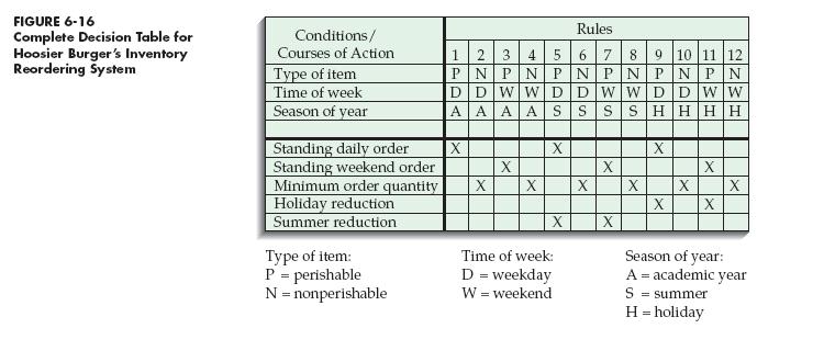
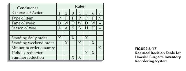
38 Modeling Logic with Decision Tables (continued) Indifferent Condition Condition whose value does not affect which action is taken for two or more rules Standard procedure for creating decision tables: Name the conditions and values each condition can assume Name all possible actions that can occur List all possible rules Define the actions for each rule (See Figure 6-16) Simplify the decision table (See Figure 6-17) 6.38
39 6.39
40 6.40
41 Process Modeling for Electronic Commerce Application Process modeling for electronic commerce projects is no different than other projects See Pine Valley Furniture example; Table
42 6.42
43 Summary Data-flow Diagrams (DFD) Symbols Rules for creating Decomposition Balancing DFDs for Analysis DFDs for Business Process Reengineering (BPR) Logic Modeling Decision Tables Process Modeling for the Internet 6.43
MULTIPLE CHOICE. Choose the one alternative that best completes the statement or answers the question.
 Exam Name MULTIPLE CHOICE. Choose the one alternative that best completes the statement or answers the question. 1) A process has a: 1) A) pronoun label B) noun phrase label C) verb phrase label D) adjective
System Analysis and Design. Data Flow Diagram. System Analysis and Design
 Data Flow Diagram 1 Data Flow diagram The dataflow diagram is a modeling tool that allows us to picture a system as a network of functional processes, connected to one another by pipelines and holding
Lab 16: Visio Introduction
 Lab 16: Visio Introduction () CONTENTS 1 Visio- Introduction to DFD Data Flow Diagraming... 2 1.1 In-Lab... 3 1.1.1 In-Lab Materials... 3 1.1.2 In-Lab Instructions... 3 2 Getting started: Let s decompose
Data Flow Diagrams System Analysis ( (
 7 Data Flow Diagrams System Analysis (1932475( Kendall & Kendall 7-1 Data Flow Diagrams A top down approach to diagramming data movement, it moves from general to specific. Graphically characterize data
System Analysis and Design
 System Analysis and Design M Umair www.m-umair.com System Description Techniques Graphical representation of any process is always better and more meaningful than its representation in words. System Analysis
Chapter No 13 Batch Management Information Systems. Management Information Systems. Compiled By: Muzammil Ahmad Khan and Kashif Shaikh
 Chapter 13 Compiled By: Muzammil Ahmad Khan Muhammad Kashif Shaikh HS-107 : Course Objectives: Upon successful completion of this course, the student will be able to: Understand the role of Information
System Analysis & design
 Assiut University Faculty of Computers and Information System Analysis & design Year 2 Academic Year 2014/ 2015 Term (2) 5 A PICTURE IS WORTH A 1,000 WORDS A process model is a graphical way of representing
Analysis and Design for Systems h. 9 th Edition
 Analysis and Design for Systems h 9 th Edition Chapter 5 Data and Process Analysis Chapter Objectives Describe data and process modeling dli concepts and tools, including data flow diagrams, a data dictionary,
Slide 1 Welcome to Fundamentals of Health Workflow Process Analysis and Redesign: Process Mapping: Gane-Sarson Notation. This is Lecture d.
 WORKFLOW ANALYSIS Audio Transcript Component 10 Unit 3 Lecture D Fundamentals of Health Workflow Process Analysis & Redesign Interpreting and Creating Process Diagrams Process Mapping Gane-Sarson Notation
Process Modelling. Data flow Diagrams. Process Modelling Data Flow Diagrams. CSE Information Systems 1
 CSE104 - Information s 1 Process Modelling Data Flow Diagrams Process Modelling Process modelling aims to graphically represent the processes which capture, manipulate, store and distribute data. data
How do archivists identify and capture records?
 QUESTION How do archivists identify and capture records? AUTOMATED SYSTEMS MEETING THE CHALLENGE Critical Skill Set: Information System Analysis and Design Skills Being able to create conceptual models
CHAPTER 4 Data and Process Modeling (Phase 2: Systems Analysis)
") CHAPTER 4 Data and Process Modeling (Phase 2: Systems Analysis) Jakrapop Maisen DATA FLOW DIAGRAMS A data flow diagram (DFD) shows how data moves through an information system but does not show program
CHAPTER 4 Data and Process Modeling (Phase 2: Systems Analysis) Jakrapop Maisen DATA FLOW DIAGRAMS A data flow diagram (DFD) shows how data moves through an information system but does not show program
Fundamentals of Health Workflow Process Analysis and Redesign
 Fundamentals of Health Workflow Process Analysis and Redesign Unit 10.3d Process Mapping Gane-Sarson Notation Slide 1 Welcome to the Gane-Sarson Notation for Data Flow Diagrams Subunit. This is the third
Data Process Modeling: Context Diagrams & Data Flow Diagrams (DFDs)
") Introduction Data Process Modeling: Context Diagrams & Data Flow Diagrams (DFDs) MIS 374 When designing/building an information system for an organization, you should consider the following questions regarding
Introduction Data Process Modeling: Context Diagrams & Data Flow Diagrams (DFDs) MIS 374 When designing/building an information system for an organization, you should consider the following questions regarding
Process Modeling. Wei-Tsong Wang 1 IIM, NCKU
 Process Modeling Based on Chapter 9 of Whitten, Bentley, and Dittman: Systems Analysis and Design for the Global Enterprise (7th Ed). McGraw Hill. 2007 Wei-Tsong Wang 1 IIM, NCKU 2 Models: Logical and
System Analysis & design
 Assiut University Faculty of Computers and Information System Analysis & design Year 2 Academic Year 2014/ 2015 Term (2) Copyright 2014 Dr. Hossam Ragab 6 data model describes the data that flow through
information process modelling DFDs Process description
 Process modelling IMS9300 IS/IM FUNDAMENTALS information process modelling DFDs Process description processes are the action part of businesses process modelling graphically represents the processes which
An Automatic Tool for Checking Consistency between Data Flow Diagrams (DFDs)
") An Automatic Tool for Checking Consistency between Data Flow Diagrams (DFDs) Rosziati Ibrahim, Siow Yen Yen Abstract System development life cycle (SDLC) is a process uses during the development of any
An Automatic Tool for Checking Consistency between Data Flow Diagrams (DFDs) Rosziati Ibrahim, Siow Yen Yen Abstract System development life cycle (SDLC) is a process uses during the development of any
Modern Systems Analysis and Design Seventh Edition
 Modern Systems Analysis and Design Seventh Edition Jeffrey A. Hoffer Joey F. George Joseph S. Valacich Structuring System Data Requirements Learning Objectives ü Concisely define each of the following
(Murlidhar Group of Institutions,Bhavnagar Road, Rajkot) by:-assit. Prof. Vijay Vora (SOOADM) MCA-III
 by:-assit. Prof. Vijay Vora (SOOADM) MCA-III") Analysis Modeling What is Analysis Modeling? Analysis modeling uses a combination of text and diagrammatic forms to depict(represent) requirements for data, function, and behavior These text and diagrammatic
Analysis Modeling What is Analysis Modeling? Analysis modeling uses a combination of text and diagrammatic forms to depict(represent) requirements for data, function, and behavior These text and diagrammatic
Unit 6 - Software Design and Development LESSON 10 DESIGN TOOLS, INPUTS, OUTPUTS, STORYBOARDS
 Unit 6 - Software Design and Development LESSON 10 DESIGN TOOLS, INPUTS, OUTPUTS, STORYBOARDS Previously Key features of programming languages Software Development Lifecycle Using tools to demonstrate
DFD Symbols. Process. Data Store Data Store Data Store
 ? Context Diagram Level 1 Diagram Level 2 Diagram DFD Symbols External Entity Source/Sink User Data Flow Process Process Data Store Data Store Data Store Rule for naming a process: The Joe Test A process
CSE Information Systems 1
 CSE1204 - Information Systems 1 Detailed Process Definitions; The Data Dictionary Data Dictionary the data dictionary is a database or repository of information about objects identified during systems
Lecture c, Process Mapping: Yourdon Notation for Data Flow Diagrams, covers Yourdon notation for data flow diagrams.
 WORKFLOW ANALYSIS Audio Transcript Component 10 Unit 3 Lecture C Fundamentals of Health Workflow Process Analysis & Redesign Interpreting and Creating Process Diagrams Process Mapping Yourdon Notation
Requests Charges. Librarian. University affiliated patrons students, faculty, staff. Media Center Staff
 Catherine Rutan INFO 530-901 Dr. Valerie Yonker Circulation of Media Materials from University Media Center: Requests Charges Librarian Circulation Desk Attendant Inquires University ID # (Primary Key)
Chapter 9. Process Modeling. McGraw-Hill/Irwin. Copyright 2007 by The McGraw-Hill Companies, Inc. All rights reserved.
 Chapter 9 Process Modeling McGraw-Hill/Irwin Copyright 2007 by The McGraw-Hill Companies, Inc. All rights reserved. Objectives Define systems modeling and differentiate logical and physical models. Define
Functional Modeling with Data Flow Diagrams
 Functional Modeling with Data Flow Diagrams Amasi Elbakush 5771668 Teaching Assistant : Daniel Alami Utrecht University 1 Introduction Data Flow Diagrams (DFDs) are a visual representation of the flow
Modelling as a Communication Tool: Introduction to Process Modelling. Modelling. Simplification in modelling. Representation in modelling
 CSE104 - Information Systems 1 Modelling as a Communication Tool: Introduction to Process Modelling The requirements specification document Must be communicated to key stakeholders Should contain: Functions
Abstract class Audit trail Class diagram Balancing Acceptance testing Closed-ended questions Baseline modules Action stubs Cohesion Activation
 Glossary of Terms Abstract class A class that has no direct instances but whose descendants may have direct instances. Acceptance testing The process whereby actual users test a completed information system,
Data and Process Modeling
 Chapter 5 Data and Process Modeling 5 CHAPTER Data and Process Modeling Chapter 5 is the second of four chapters in the systems analysis phase of the SDLC. This chapter discusses data and process modeling
17/03/2018. Meltem Özturan
 Meltem Özturan www.mis.boun.edu.tr/ozturan/samd 2 1 Traditional Approach to Requirements Traditional Analysis Model Data flow diagrams Process description Data flow definiton Data store definition (Entity-Relationship
Fundamentals of Health Workflow Process Analysis and Redesign
 Fundamentals of Health Workflow Process Analysis and Redesign Process Mapping: Yourdon Notation for Data Flow Diagrams This material Comp10_Unit3c was developed by Duke University, funded by the Department
13/11/2017. Meltem Özturan misprivate.boun.edu.tr/ozturan/mis515
 Meltem Özturan misprivate.boun.edu.tr/ozturan/mis515 2 1 Traditional Approach to Requirements Data Flow Diagram (DFD) A graphical system model that shows all of the main requirements for an information
Fundamentals of Health Workflow Process Analysis and Redesign
 Fundamentals of Health Workflow Process Analysis and Redesign This material Comp0_Unit3d was developed by Duke University, funded by the Department of Health and Human Services, Office of the National
Module 5. Function-Oriented Software Design. Version 2 CSE IIT, Kharagpur
 Module 5 Function-Oriented Software Design Lesson 12 Structured Design Specific Instructional Objectives At the end of this lesson the student will be able to: Identify the aim of structured design. Explain
1. The narratives, diagrams, charts, and other written materials that explain how a system works are collectively called
 CH 3 MULTIPLE CHOICE 1. The narratives, diagrams, charts, and other written materials that explain how a system works are collectively called a) documentation. b) data flows. c) flowcharts. d) schema.
Data. Entities. Accounting Information Systems. Chapter 4: Data Management
 Accounting Information Systems Chapter 4: Data Management Data Data may be defined broadly to include two interrelated components: Data Models that provide structure to data File Orientation Data-base
Process Modeling. Chapter 7. Class 05: Process Modeling 1
 Process Modeling Chapter 7 Class 05: Process Modeling 1 Process Design Seldom the responsibility of the database designer or DBA However, understanding the basics aids communication with the process designers
Process Modeling. Business Process Example. Process Design
 Process Modeling Chapter 7 Class 05: Process Modeling 1 Process Design Seldom the responsibility of the database designer or DBA However, understanding the basics aids communication with the process designers
Requirements Engineering
 Requirements Engineering Semi-Formal Specification: Structural Functional Requirements Structured Analysis Data Flow Diagrams SADT IDEF0 1 Back to the past GO/AO OO SA (DT) DFD SADT IDEF (Back to the future)
Lecture Notes. Structured Systems Analysis
 Lecture Notes Structured Systems Analysis Lecture 3 Structured Analysis & Data Flow Diagrams Written by Dr. Fred Grossman Copyright 1999 Fred Grossman All Rights Reserved Structured Systems Analysis Structured
SE Assignment III. 1. List and explain primitive symbols used for constructing DFDs. Illustrate the use of these symbols with the help of an example.
 SE Assignment III 1. List and explain primitive symbols used for constructing DFDs. Illustrate the use of these symbols with the help of an example. There are essentially 5 different types of symbols used
We move from a general information system to a Computer Based Information System
 Introduction to Information Systems: In this section of the course we start to think of the computer as just being a component in a system which may contain one or many computers linked together. An Information
Information Technology Audit & Cyber Security
 Information Technology Audit & Cyber Security Structured Data Requirements Systems & Infrastructure Lifecycle Management with E-R LEARNING OBJECTIVES Explain the role of conceptual data modeling in the
Session 2b: structured specifications Purpose and criteria Structured specification components Introduction to dataflow diagrams
 Session 2b: structured specifications Purpose and criteria Structured specification components Introduction to dataflow diagrams COMP 320 / 420, Spring, 2018 Conrad Weisert Criteria for the ESD (from session
An Introduction to Business Process Modeling using Data Flow Diagrams
 An Introduction to Business Process Modeling using Data Flow Diagrams BSAD 141 Dave Novak BDIS: 2.2 (61-77) Lecture Overview Systems and Business processes Business process models Data Flow Diagrams (DFDs)
Darshan Institute of Engineering & Technology for Diploma Studies
 REQUIREMENTS GATHERING AND ANALYSIS The analyst starts requirement gathering activity by collecting all information that could be useful to develop system. In practice it is very difficult to gather all
Chapter 4: Data Management
 Accounting Information Systems: Essential Concepts and Applications Fourth Edition by Wilkinson, Cerullo, Raval, and Wong-On-Wing Chapter 4: Data Management Slides Authored by Somnath Bhattacharya, Ph.D.
ASSIGNMENT- I Topic: Functional Modeling, System Design, Object Design. Submitted by, Roll Numbers:-49-70
 ASSIGNMENT- I Topic: Functional Modeling, System Design, Object Design Submitted by, Roll Numbers:-49-70 Functional Models The functional model specifies the results of a computation without specifying
Activity Diagram Written Date : September 02, 2016
 Written Date : September 02, 2016 s describe how activities are coordinated to provide a service which can be at different levels of abstraction. Typically, an event needs to be achieved by some operation,
Modern Systems Analysis and Design
 Modern Systems Analysis and Design Sixth Edition Jeffrey A. Hoffer Joey F. George Joseph S. Valacich Designing Databases Learning Objectives Concisely define each of the following key database design terms:
Chapter : Analysis Modeling
 Chapter : Analysis Modeling Requirements Analysis Requirements analysis Specifies software s operational characteristics Indicates software's interface with other system elements Establishes constraints
Database Environment. Pearson Education 2009
 Chapter 2 Database Environment 1 Chapter 2 - Objectives Purpose of three-level database architecture. Contents of external, conceptual, and internal levels. Purpose of external/conceptual and conceptual/internal
CHAPTER 19: Building a Preliminary Behavioral Model
 1 z 7 CHAPTER 19: Building a Preliminary Behavioral Model Things are always at their best in their beginning. Blaise Pascal Lettres Provinciales, 1656-1657, no. 4 IN THIS CHAPTER, YOU WILL LEARN: Why a
Chapter 10. Object-Oriented Analysis and Modeling Using the UML. McGraw-Hill/Irwin
 Chapter 10 Object-Oriented Analysis and Modeling Using the UML McGraw-Hill/Irwin Copyright 2007 by The McGraw-Hill Companies, Inc. All rights reserved. Objectives 10-2 Define object modeling and explain
Overview. What is system analysis and design? Tools and models Methodologies
 Overview What is system analysis and design? Tools and models Methodologies Information Systems What is a system? Why do systems fail? What is systems analysis and design? How do we do systems analysis?
ABSTRACTION OF DATA FLOW DIAGRAM FOR A C PROGRAM
 International Journal of Operations System and Human Resource Management Vol. 2, Nos. 1-2, January-December 2012, pp. 69 77 International Science Press ABSTRACTION OF DATA FLOW DIAGRAM FOR A C PROGRAM
Progress Report. Object-Oriented Software Development: Requirements elicitation (ch. 4) and analysis (ch. 5) Object-oriented software development
 and analysis (ch. 5) Object-oriented software development") Progress Report Object-Oriented Software Development: Requirements elicitation (ch. 4) and analysis (ch. 5) CS 4354 Summer II 2014 Jill Seaman So far we have learned about the tools used in object-oriented
Progress Report Object-Oriented Software Development: Requirements elicitation (ch. 4) and analysis (ch. 5) CS 4354 Summer II 2014 Jill Seaman So far we have learned about the tools used in object-oriented
Software Engineering Prof.N.L.Sarda IIT Bombay. Lecture-11 Data Modelling- ER diagrams, Mapping to relational model (Part -II)
") Software Engineering Prof.N.L.Sarda IIT Bombay Lecture-11 Data Modelling- ER diagrams, Mapping to relational model (Part -II) We will continue our discussion on process modeling. In the previous lecture
Software Engineering Prof.N.L.Sarda IIT Bombay Lecture-11 Data Modelling- ER diagrams, Mapping to relational model (Part -II) We will continue our discussion on process modeling. In the previous lecture
1. i. What are the 3 major components of a information system and show their relationship input output
 Higher National Diploma in Information Technology First Year, Second semesterexamination-2011 IT2005: System Analysis and Design Answer Script No. of pages: 11 1. i. What are the 3 major components of
SOFTWARE ANALYSIS & DESIGN TOOLS
 SOFTWARE ANALYSIS & DESIGN TOOLS http://www.tutorialspoint.com/software_engineering/software_analysis_design_tools.htm Copyright tutorialspoint.com Software analysis and design includes all activities,
Lab # 1. Structuring System Requirements: Diagrams
 Lab # 1 Structuring System Requirements: Diagrams Objectives 1. Use Case diagrams 2. Class Objects (CO) diagrams 3. Context Data Flow Diagrams (Context DFDs) 4. Level-0 Data Flow Diagrams (Level-0 DFDs)
Systems Analysis and Design in a Changing World, Fourth Edition
 Systems Analysis and Design in a Changing World, Fourth Edition Systems Analysis and Design in a Changing World, 4th Edition Learning Objectives Explain the purpose and various phases of the systems development
CS504-Softwere Engineering -1 Solved Objective Midterm Papers For Preparation of Midterm Exam
 CS504-Softwere Engineering -1 Solved Objective Midterm Papers For Preparation of Midterm Exam MIDTERM EXAMINATION 2010 Question No: 1 ( Marks: 1 ) - Please choose one By following modern system engineering
(Team Name) (Project Title) Software Design Document. Student Name (s):
 (Project Title) Software Design Document. Student Name (s):") (Team Name) (Project Title) Software Design Document Student Name (s): TABLE OF CONTENTS 1. INTRODUCTION 2 1.1Purpose 2 1.2Scope 2 1.3Overview 2 1.4Reference Material 2 1.5Definitions and Acronyms 2 2.
(Team Name) (Project Title) Software Design Document Student Name (s): TABLE OF CONTENTS 1. INTRODUCTION 2 1.1Purpose 2 1.2Scope 2 1.3Overview 2 1.4Reference Material 2 1.5Definitions and Acronyms 2 2.
Chapter 13. Application Architecture and Modeling. McGraw-Hill/Irwin. Copyright 2007 by The McGraw-Hill Companies, Inc. All rights reserved.
 Chapter 13 Application Architecture and Modeling McGraw-Hill/Irwin Copyright 2007 by The McGraw-Hill Companies, Inc. All rights reserved. Objectives 13-2 Define an information system s architecture in
Identify the guidelines for system development. Discuss the purpose of the activities performed in the analysis phase
 Discovering Computers 2010 Living in a Digital World Objectives Overview Define system development and list the system development phases Identify the guidelines for system development Discuss the importance
Chapter 2: The Database Development Process
 : The Database Development Process Modern Database Management 7 th Edition Jeffrey A. Hoffer, Mary B. Prescott, Fred R. McFadden 1 Objectives Definition of terms Describe system development life cycle
Structured Systems Analysis and Design
 Structured Systems Analysis and Design Sogeti University February 1, 2011 Dr. Kevin P. Duffy What is SSAD? A few definitions to start everybody off on the same page. System: A collection of interrelated
APPENDIX M INTRODUCTION TO THE UML
 M INTRODUCTION TO THE UML This appendix, written only for those readers not familiar with the topic, provides a brief introduction, which cannot be considered as exhaustive, to the UML. The UML is a general-purpose
Meltem Özturan
 Meltem Özturan www.mis.boun.edu.tr/ozturan/samd 1 2 Modeling System Requirements Object Oriented Approach to Requirements OOA considers an IS as a set of objects that work together to carry out the function.
Modelling: Review. Modelling Information Systems. Models in analysis and design. Process Modelling. Modelling perspectives
 Modelling: Review IMS100 Systems Analysis and Design Topic Review of Process Modelling Why do we do it? Communication and understanding Simplification all models are simplifications of the real world:
PPSC Competitive Exam for the Post of System Analyst
 PPSC Competitive Exam for the Post of System Analyst Question Paper Along with Answer Key Date: 21 st June, 2014 Time: 09: 00 AM to 11:00 AM Total Number of Questions: 100 Q 1. Which of the following is
Guide to EPC Process Modelling
 Guide to EPC Process Modelling Guideline to EPC Process Modelling Standard 1. PURPOSE The purpose of this document is to provide a guideline to the Event-Driven Process Chain (EPC) modelling notation used
AllFusion Process Modeler
 AllFusion Process Modeler User Guide r7.2 This documentation and any related computer software help programs (hereinafter referred to as the Documentation ) is for the end user s informational purposes
Software Development. Designing Software
 Software Development Designing Software Modules Modular programming is a software design technique that emphasizes separating the functionality of a program into independent, interchangeable modules, such
Data Flow Diagrams Examples
 1 of 6 20-Jan-12 1:42 AM Information Systems College of Business Administration University of Missouri - St. Louis Data Flow Diagrams Examples We will study a variety of diagramming tools this semester.
Modern Systems Analysis and Design. Third Edition. Jeffrey A. Hoffer Joey F. George Joseph S. Valacich. Chapter 17 System Implementation
 Modern Systems Analysis and Design Third Edition Jeffrey A. Hoffer Joey F. George Joseph S. Valacich Chapter 17 System Implementation 17.1 Copyright 2002 Prentice-Hall, Inc. Learning Objectives Describe
SYSTEM DESIGN. 1 Introduction: 1.1 Overview: 1.2 Scope:
 SYSTEM DESIGN 1 Introduction: The purpose of System Design is to create a technical solution that satisfies the functional requirements for the system. During analysis, the focus is on what needs to be
06. Analysis Modeling
 06. Analysis Modeling Division of Computer Science, College of Computing Hanyang University ERICA Campus 1 st Semester 2017 Overview of Analysis Modeling 1 Requirement Analysis 2 Analysis Modeling Approaches
CS403- Database Management Systems Solved MCQS From Midterm Papers. CS403- Database Management Systems MIDTERM EXAMINATION - Spring 2010
 CS403- Database Management Systems Solved MCQS From Midterm Papers April 29,2012 MC100401285 Moaaz.pk@gmail.com Mc100401285@gmail.com PSMD01 CS403- Database Management Systems MIDTERM EXAMINATION - Spring
Oracle Data Modelling & Database Design Course Content:35-40hours
 Oracle Data Modelling & Database Design Course Content:35-40hours Course Outline Introduction to Modeling List the reasons why modeling is important Describe the phases of the Database and Application
Methods for requirements engineering
 Methods for requirements engineering Objectives To explain the role of methods and techniques in requirements engineering To introduce data-flow modelling To introduce semantic data modelling To introduce
Darshan Institute of Engineering & Technology for Diploma Studies Rajkot Unit-1
 Failure Rate Darshan Institute of Engineering & Technology for Diploma Studies Rajkot Unit-1 SOFTWARE (What is Software? Explain characteristics of Software. OR How the software product is differing than
System Models. Minsoo Ryu. Hanyang University. Real-Time Computing and Communications Lab., Hanyang University
 System Models Minsoo Ryu Hanyang University 1. Context Models 2. Structural Model 3. Behavioural Models 4. Object Models Contents 2 2 Building a System Model User requirements should be written in natural
BPMN Getting Started Guide
 Enterprise Studio BPMN Getting Started Guide 2017-09-21 Applies to: Enterprise Studio 3.0.0, Team Server 3.0.0 Table of contents 1 About modeling with BPMN 5 1.1 What is BPMN? 5 1.2 BPMN modeling 5 1.3
Introduction to Some Requirements Specification Tools (EEM, ELH, ECD, EAP) -Some Basic Concepts- Dr. Ernest Cachia
 -Some Basic Concepts- Dr. Ernest Cachia") Introduction to Some Requirements Specification Tools (EEM, ELH, ECD, EAP) -Some Basic Concepts- Dr. Ernest Cachia SSADM Diagram Relationships DFD * ERD ELH Entity Life History (ELH) Diagrams Some basic
Introduction to Some Requirements Specification Tools (EEM, ELH, ECD, EAP) -Some Basic Concepts- Dr. Ernest Cachia SSADM Diagram Relationships DFD * ERD ELH Entity Life History (ELH) Diagrams Some basic
CMPSC 487W Software Engineering and Design Group Assignment #3 Fall 2017
 CMPSC 487W Software Engineering and Design Group Assignment #3 Fall 2017 Due Date: Wednesday, November 8, 2017 Total Points: 100 Description: The first two steps of developing a software product in ICONIX
INFS 328 Systems Analysis and Design
 INFS 328 Systems Analysis and Design Session 13 Systems Analysis and Construction Tools Lecturer: Prof. Ellis Edwin Badu, Dept. of Information Studies Contact Information: eebadu@ug.edu.gh College of Education
OBJECTIVES DEFINITIONS CHAPTER 1: THE DATABASE ENVIRONMENT AND DEVELOPMENT PROCESS. Figure 1-1a Data in context
 OBJECTIVES CHAPTER 1: THE DATABASE ENVIRONMENT AND DEVELOPMENT PROCESS Modern Database Management 11 th Edition Jeffrey A. Hoffer, V. Ramesh, Heikki Topi! Define terms! Name limitations of conventional
Chapter 5: Structural Modeling
 Chapter 5: Structural Modeling Objectives Understand the rules and style guidelines for creating CRC cards, class diagrams, and object diagrams. Understand the processes used to create CRC cards, class
InterPARES 2 Project
 International Research on Permanent Authentic Records in Electronic Systems Integrated Definition Function Modeling (IDEFØ): A Primer InterPARES Project Coordinator 04 August 2007 1 of 13 Integrated Definition
IMS1002/CSE1205 Lectures 1
 IMS1002/CSE1205 Systems Analysis and Design Lecture 2 & 3 Introduction to Data Modelling Entity Relationship Modelling Data Modelling Focus on the information aspects of the organisation In a database
Data Analysis 1. Chapter 2.1 V3.1. Napier University Dr Gordon Russell
 Data Analysis 1 Chapter 2.1 V3.1 Copyright @ Napier University Dr Gordon Russell Entity Relationship Modelling Overview Database Analysis Life Cycle Components of an Entity Relationship Diagram What is
Business Process Modeling with BPMN
 member of Business Process Modeling with BPMN Knut Hinkelmann Elements of BPMN Elements of BPMN can be divided into 4 categories: Flow Objects Connectors Artefacts Swimlanes Activities Sequence Flow Data
SE 2730 Final Review
 SE 2730 Final Review 1. Introduction 1) What is software: programs, associated documentations and data 2) Three types of software products: generic, custom, semi-custom Why is semi-custom product more
Business Process Modeling. Version 25/10/2012
 Business Process Modeling Version 25/10/2012 Maurizio Morisio, Marco Torchiano, 2012, 2013 3 BP Aspects Process flow Process modeling UML Activity Diagrams BPMN Information Conceptual modeling UML Class
Entity Relationship Modelling
 Entity Relationship Modelling Overview Database Analysis Life Cycle Components of an Entity Relationship Diagram What is a relationship? Entities, attributes, and relationships in a system The degree of
Object-Oriented Systems Analysis and Design Using UML
 10 Object-Oriented Systems Analysis and Design Using UML Systems Analysis and Design, 8e Kendall & Kendall Copyright 2011 Pearson Education, Inc. Publishing as Prentice Hall Learning Objectives Understand
Full file at
 Modern Database Management, 10e (Hoffer/Ramesh/Topi) Chapter 2 Modeling Data in the Organization 1) Data modeling may be the most important part of the systems development process because: A) data characteristics