USBoard. Operating Manual. Version November USBoard-OperatingManual Neobotix GmbH all rights reserved 1 of 25
|
|
|
- Sheena Horn
- 6 years ago
- Views:
Transcription


1 USBoard Operating Manual Version November 2017 USBoard-OperatingManual Neobotix GmbH all rights reserved 1 of 25
2 Contents 1 Introduction Technical data USBoard Ultrasonic sensor Bosch Parkpilot Housing Operating principle Commissioning Command set CAN-Communication Addresses Commands...8 CMD_CONNECT...8 CMD_SET_CHANNEL_ACTIVE...8 CMD_GET_DATA_1TO8...9 CMD_GET_DATA_9TO CMD_WRITE_PARASET...11 CMD_WRITE_PARASET_TO_EEPROM...12 CMD_READ_PARASET...13 CMD_GET_ANALOGIN RS-232-Communication Dimensions and pin assignment Dimensions Pin assignment Graphical parameter editor Introduction First Steps Configuring the USBoard Additional parts Connectors Accessories...23 Configuration cable...23 Sensor cable sets...24 Connector sets...24 Ultrasonic sensor URF Legal notes...25 USBoard-OperatingManual Neobotix GmbH all rights reserved 2 of 25
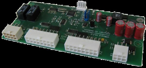
3 1 Introduction Ultrasonic sensors are used to measure the distance to objects within the sensor's metering range. The metering principle is based on measuring the time of flight of a sound pulse. This pulse is created by the sensor, reflected by an obstacle and then received by the sensor. The USBoard is capable of operating up to 16 ultrasonic sensors of type Bosch Parkpilot URF6 (also known as URF7 or USS4). It can be used for collision detection on big vehicles like buses, farm machines or construction machinery. The board features easy commissioning, comfortable parametrization and a wide range of custom settings. Defining warning and alarm distances allows an easy detection of possible collisions. Furthermore four analogue inputs are available on the board. These inputs can be used to add other sensors to the system without the need for any additional boards. 2 Technical data 2.1 USBoard Supply voltage from +9 VDC up to +60 VDC, max. 5 W Digital communication via CAN or RS-232 Optical indicators for warning and alarm distance Relay outputs for warning and alarm distance Sensor outputs protected against supply voltage Four analogue inputs (0 V 5 V) Weight: 93 g Customs tariff number: Order number: X Ultrasonic sensor Bosch Parkpilot Uses frequencies from 42 khz to 45 khz Range: 0.15 m up to 1.5 m Field of view 120 x 60 Order number: X200 Customs tariff number: Figure 1: Sensor's field of view USBoard-OperatingManual Neobotix GmbH all rights reserved 3 of 25

4 3 Housing By default the USBoard is delivered as OEM-component without housing. If required, an appropriate housing can be supplied. 4 Operating principle An ultrasonic sensor creates a sound pulse that is reflected by obstacles and then returns to the sensor. By measuring the time between creating and receiving the sound pulse, the USBoard is able to calculate the distance between the sensor and the closest obstacle. Activating the sensors cyclically one after the other reduces interfering signals (Cross- Talk). The activation sequence of the sensors is 1, 5, 9, 13, 2, 6, 10, 14, 3, 7, 11, 15, 4, 8, 12, 16. A CAN and a RS-232 communication interface can be used to acquire distances measured by the sensors as well as the data from the analogue inputs. For each sensor a warning and an alarm distance can be defined by software. This allows to easily use the board for collision protection. As soon as the distance measured by a sensor falls below the according warning distance, a LED on the board lights up and a relay is switched. A second LED and another relay indicate that an obstacle was detected within the alarm distance of one or more sensors. Warning and alarm distances are defined in the parameter set. The USBoard is no safety system and can only provide supporting, non-safe information. Never use the USBoard for safeguarding of dangerous areas or movements. 5 Commissioning The USBoard is delivered with settings according to table 1 and is ready for instant use. An individual configuration can be done by Neobotix, if required, or by the customer. The included graphical parameter editor allows to program the board via an RS-232-port. After uploading the parameter set to the board, the USBoard immediately uses the new settings and optionally stores them in the non-volatile on-board EEPROM. The USBoard can be used in four different ways: 1. Monitoring the warning and alarm distances with the LEDs on the board. 2. The relay outputs are connected to appropriate indicators and used for monitoring the fields. 3. The measured distances are acquired via the CAN- or RS-232-interface and interpreted by an external computer. 4. A combination of the possibilities described above. USBoard-OperatingManual Neobotix GmbH all rights reserved 4 of 25
5 6 The USBoard uses a parameter set which allows a custom configuration. The graphical parameter editor can be used to easily manipulate the board's settings, store them on the host computer's hard drive, write them to the EEPROM on the USBoard or read the current values from the board. Table 1 shows the structure of the 54 bytes parameter set. Byte-Nr. 1 CAN Baud rate: 0 = 1000 kbaud (default) 1 = 500 kbaud 2 = 250 kbaud 3 = 125 kbaud 4 = 100 kbaud 5 = 50 kbaud Content 2-5 CAN basic address The basic address is build from bytes 1-4 as: CAN basic address = (Byte 4 << 24) (Byte 3 << 16) (Byte 2 << 8) Byte 1 CAN basic address = 0x400 (default) 6 CAN Extended ID 0 = do not use CAN Extended ID (default) 1 = use CAN Extended ID 7 Transmission mode for measurement data 0 = Send on request (default) 1 = Send continuously via CAN 2 = Send continuously via RS = Send continuously via CAN and RS Transmission interval when sending continuously 0 = 0,5 s 1 = 1,0 s 2 = 2,0 s 9 Sensor 1 to 8 active (byte is bit-coded); default = all active 10 Sensor 9 to 16 active (byte is bit-coded); default = all active Warning distance of sensors 1 16, in cm; default = 100 cm Alarm distance of sensors 1 16, in cm; default = 30 cm Any value, obsolete Serial number, read only Table 1: of the USBoard USBoard-OperatingManual Neobotix GmbH all rights reserved 5 of 25
6 7 Command set Table 2 shows the available commands of the USBoard. Command Value Description CMD_CONNECT 0 Check connection CMD_SET_CHANNEL_ACTIVE 1 Activate channel for sending / receiving CMD_GET_DATA_1TO8 2 Request data of sensors 1 to 8 CMD_GET_DATA_9TO16 3 Request data of sensors 1 to 8 CMD_WRITE_PARASET 4 Upload parameter set to board (volatile) CMD_WRITE_PARASET_TO_EEPROM 5 Write parameter set to board's EEPROM (non-volatile) CMD_READ_PARASET 6 Read current parameter set CMD_GET_ANALOGIN 7 Read values of analog inputs CMD_SET_DEBUG_PARA 8 For debugging only CMD_GET_DEBUG_PARA 9 For debugging only CMD_UNKNOWN 10 For debugging only Table 2: List of the commands of USBoard USBoard-OperatingManual Neobotix GmbH all rights reserved 6 of 25
7 8 CAN-Communication 8.1 Addresses The default basic address is 0x400. This basic address can be changed in the parameter set. The USBoard uses the following addresses for CAN-communication: Address Basic address Basic address + 1 Basic address + 2 Basic address + 3 Basic address + 4 Basic address + 5 Basic address + 6 Basic address + 7 Basic address + 8 Basic address + 9 Message Receive commands Answer to CMD_CONNECT 1. Answer to CMD_GET_DATA_1TO8 2. Answer to CMD_GET_DATA_1TO8 1. Answer to CMD_GET_DATA_9TO16 2. Answer to CMD_GET_DATA_9TO16 Answer to CMD_READ_PARASET Answer to CMD_GET_ANALOGIN Answer to CMD_WRITE_PARASET Answer to CMD_WRITE_PARASET_TO_EEPROM Table 3: List of used CAN-addresses USBoard-OperatingManual Neobotix GmbH all rights reserved 7 of 25
8 8.2 Commands CMD_CONNECT Use this command to establish and check the connection to the board. Command format ID: Basic address CMD_CONNECT Answer format ID: Basic address + 1 CMD_CONNECT CMD_SET_CHANNEL_ACTIVE This command can be used to activate / deactivate individual sensors without transmitting the complete parameter set. Two bytes for the channels 1 to 8 and 9 to 16 contain the information whether the sensors should be active. These bytes are bit-coded, each bit representing the state of one sensor. Every active channel is marked with a 1. Example: 1.Byte = 0x1F Channels 1 to 5 are active, channels 6 to 8 are not active Command format ID: Basic address CMD_SET_CHANNEL_ACTIVE Sensor 1 to 8 active Sensor 9 to 16 active Answer format No Answer USBoard-OperatingManual Neobotix GmbH all rights reserved 8 of 25
9 CMD_GET_DATA_1TO8 This command is used to request the readings of sensors 1 to 8. Command format ID: Basic address CMD_GET_DATA_1TO The answer is made up of two messages. Answer format 1 ID: Basic address + 2 CMD_GET_ DATA_1TO8 0 reading of sensor 1 in [cm] reading of sensor 2 in [cm] reading of sensor 3 in [cm] reading of sensor 4 in [cm] 0 Reserved Answer format 2 ID: Basic address + 3 CMD_GET_ DATA_1TO8 1 reading of sensor 5 in [cm] reading of sensor 6 in [cm] reading of sensor 7 in [cm] reading of sensor 8 in [cm] 0 Reserved USBoard-OperatingManual Neobotix GmbH all rights reserved 9 of 25
10 CMD_GET_DATA_9TO16 This command is used to request the readings of sensors 9 to 16. Command format ID: Basic address CMD_GET_DATA_9TO The answer is made up of two messages. Answer format 1 ID: Basic address + 4 CMD_GET_ DATA_9TO16 0 reading of sensor 9 in cm reading of sensor 10 in cm reading of sensor 11 in cm reading of sensor 12 in cm 0 Reserved Answer format 2 ID: Basic address + 5 CMD_GET_ DATA_9TO16 1 reading of sensor 13 in cm reading of sensor 14 in cm reading of sensor 15 in cm reading of sensor 16 in cm 0 Reserved USBoard-OperatingManual Neobotix GmbH all rights reserved 10 of 25
11 CMD_WRITE_PARASET Use this command to transfer a complete parameter set to the USBoard. The parameters are stored volatile, which means that they will be lost when the board is switched off. To comfortably configure the board, use the graphical parameter editor. After transmitting the parameter set, it will immediately be used by the board. Each set is made up of nine messages sent one after another. Command format ID: Basic address CMD_WRITE_PARASET 0 Byte 1 Byte 2 Byte 3 Byte 4 Byte 5 Byte 6 CMD_WRITE_PARASET 1 Byte 7 Byte 8 Byte 9 Byte 10 Byte 11 Byte CMD_WRITE_PARASET 8 Byte 49 Byte 50 Byte 51 Byte 52 Byte 53 Byte 54 The first eight messages receive the following answer: Answer format ID: Basic address + 8 CMD_WRITE_PARASET The answer to the last message contains the sum of all bytes in the parameter set. Answer format ID: Basic address + 8 CMD_WRITE_PARASET Checksum low byte Checksum high byte USBoard-OperatingManual Neobotix GmbH all rights reserved 11 of 25
12 CMD_WRITE_PARASET_TO_EEPROM Use this command to write a complete parameter set into the board's EEPROM. The parameters are stored non-volatile, which means that they will be used again, the next time the USBoard is switched on. To comfortably configure the board, use the graphical parameter editor. The parameter set will immediately be used after transmission. A set is made up of nine messages sent one after another. Command format ID: Basic address CMD_WRITE_PARASET _TO_EEPROM 0 Byte 1 Byte 2 Byte 3 Byte 4 Byte 5 Byte 6 CMD_WRITE_PARASET _TO_EEPROM 1 Byte 7 Byte 8 Byte 9 Byte 10 Byte 11 Byte CMD_WRITE_PARASET _TO_EEPROM 8 Byte 49 Byte 50 Byte 51 Byte 52 Byte 53 Byte 54 The first eight messages receive the following answer: Answer format ID: Basic address + 9 CMD_WRITE_PARASET The answer to the last message contains the sum of all bytes in the parameter set. Answer format ID: Basic address + 9 CMD_WRITE_PARASET Checksum low byte Checksum high byte USBoard-OperatingManual Neobotix GmbH all rights reserved 12 of 25
13 CMD_READ_PARASET Use this command to read a complete parameter set from the USBoard. The answer is made up of nine messages sent one after another. Command format ID: Basic address CMD_READ_PARASET Answer format ID: Basic address + 6 CMD_READ_PARASET 0 Byte 1 Byte 2 Byte 3 Byte 4 Byte 5 Byte 6 CMD_READ_PARASET 1 Byte 7 Byte 8 Byte 9 Byte 10 Byte 11 Byte CMD_READ_PARASET 8 Byte 49 Byte 50 Byte 51 Byte 52 Byte 53 Byte 54 USBoard-OperatingManual Neobotix GmbH all rights reserved 13 of 25
14 CMD_GET_ANALOGIN Use this command to acquire the data of the four analog inputs. Because the resolution of the on-board AD-converter is 12 bit, the first part of the answer is made up of the four low bytes. Bytes 5 and 6 contain the upper 4 bits of the four channels, coded as follows: D5 D6 4 High Bits channel 2 4 High Bits channel 1 4 High Bits channel 4 4 High Bits channel 3 Command format ID: Basic address CMD_GET_ANALOGIN Answer format ID: Basic address + 7 CMD_GET_ANALOGIN analog data channel 1 Low Byte analog data channel 2 Low Byte analog data channel 3 Low Byte analog data channel 4 Low Byte analog data channel 1 2 High Bits analog data channel 3 4 High Bits 0 USBoard-OperatingManual Neobotix GmbH all rights reserved 14 of 25
15 9 RS-232-Communication The RS-232-interface runs at Baud. Communication via RS-232 uses the same format as the CAN-communication except for the following addition: Every message from the USBoard begins with a start byte which must have the value 0xFF. After each message, made up of eight data bytes, a 16 bit checksum is sent. Because of this a complete message is 11 bytes long. Byte 1 Byte 2-9 Byte 10 Byte 11 0xFF Data bytes Bit checksum High Byte 16 Bit checksum Low Byte The checksum is calculated with an CRC-CCITT algorithm using 8 databytes. Messages to the USBoard contain only databytes 1-8. Example implementation of the algorithm (C - code): unsigned int getchecksum(unsigned char* c, int inumbytes) { unsigned int ucrc16; unsigned char ucdata[2]; ucrc16 = 0; ucdata[0] = 0; while(inumbytes--) { ucdata[1] = ucdata[0]; ucdata[0] = *c++; if(ucrc16 & 0x8000) { ucrc16 = (ucrc16 & 0x7fff) << 1; ucrc16^= 0x1021; //generator polynom } else { ucrc16 <<= 1; } ucrc16^= (unsigned int)(ucdata[0]) ((unsigned int)(ucdata[1])<< 8); } return ucrc16; } USBoard-OperatingManual Neobotix GmbH all rights reserved 15 of 25
16 10 Dimensions and pin assignment 10.1 Dimensions Figure 2: Dimensions of the USBoard Move S1 to position ON to activate the CAN terminating resistor. The mounting hole at the bottom right corner is electrically connected to the ground plane of the USBoard. Please insulate this mounting point if necessary in your installation. The USBoard can be mounted both horizontally and on walls. Please note that when mounted upside down the relays might malfunction. The data output is not affected by the mounting orientation. USBoard-OperatingManual Neobotix GmbH all rights reserved 16 of 25
17 10.2 Pin assignment Connector X1 Molex Mini-Fit Jr., 6-pin Pin 1 Power supply input 2 CAN High 3 CAN High 4 Ground 5 CAN Low 6 CAN Low Description Pins 2 and 3 are bridged, as well as pins 5 and 6. This allows two CAN cables (CAN-in and CAN-out) to be connected easily. Connector X2 Molex Mini-Fit Jr., 16-pin Pin 1 Sensor power supply 0 V 2 Sensor power supply 0 V 3 Sensor power supply 0 V 4 Sensor power supply 0 V 5 Sensor 1 6 Sensor 3 7 Sensor 5 8 Sensor 7 9 Sensor power supply +8 V 10 Sensor power supply +8 V 11 Sensor power supply +8 V 12 Sensor power supply +8 V 13 Sensor 2 14 Sensor 4 15 Sensor 6 16 Sensor 8 Description USBoard-OperatingManual Neobotix GmbH all rights reserved 17 of 25
18 Connector X3 Molex Mini-Fit Jr., 16-pin Pin 1 Sensor 9 2 Sensor 11 3 Sensor 13 4 Sensor 15 5 Sensor power supply 0 V 6 Sensor power supply 0 V 7 Sensor power supply 0 V 8 Sensor power supply 0 V 9 Sensor Sensor Sensor Sensor Sensor power supply +8 V 14 Sensor power supply +8 V 15 Sensor power supply +8 V 16 Sensor power supply +8 V Description Connector X4 Molex Mini-Fit Jr., 8-pin Pin Description 1 RS-232 transmit 2 Relay warning distance common contact 3 Relay warning distance NC (normally closed) 4 Relay alarm distance NO (normally open) 5 RS-232 receive 6 Relay warning distance NO (normally open) 7 Relay alarm distance common contact 8 Relay alarm distance NC (normally closed) Analogue input connector TE Connectivity HE14, 4-pins Pin 1 Analogue input 1 2 Analogue input 2 3 Analogue input 3 4 Analogue input 4 Description Sensors Housing: TE , Contacts: TE Pin 1 Send / receive 2 Sensor power supply 0 V 3 Sensor power supply +8 V Description USBoard-OperatingManual Neobotix GmbH all rights reserved 18 of 25
 Java Runtime Environment 1.")
19 11 Graphical parameter editor 11.1 Introduction The USBoard is provided together with the USBoard configuration GUI, a graphical parameter editor. The USBoardGUI requires a PC with: Microsoft Windows as operating system RS-232 interface (COM port) Java Runtime Environment 1.5 or later The connection between serial interface and USBoard is established by a special cable which can be obtained from Neobotix or self-constructed using the specifications in chapter This cable also connects the USBoard with an appropriate power supply (see chapter 2.1). A working supply is indicated by an LED on the long side of the board. To start the application, simply double-click on the start.bat file. Make sure to use the program version that matches your operating system First Steps Establishing a connection Before starting a connection via the USBoardGUI, please make sure that the USBoard is connected to the PC's RS-232 interface to a power supply (LED lights up). Now select the correct communication port in the application and click the Connect button, to create the connection. Figure 3: Connection via serial interface COM4 Receiving data After establishing a connection, first data will show up. Depending on currently set parameters, measured data are updated automatically in defined interval or can be read manually by clicking the Request buttons. If the measured distance of a sensor falls below its specified warning distance, the value is displayed yellow. In case of underrunning the alarm distance, the colour changes to red. As long as any measured distance is below the according warning or alarm distance, the according LED on the USBoard will light up and the relay is activated. USBoard-OperatingManual Neobotix GmbH all rights reserved 19 of 25


20 Figure 4: Example for measured values in green, yellow (warning) and red (alarm) range The measured values of the analogue inputs (voltage range 0 V 5 V) are displayed percentaged below the distances. Closing the connection To close the connection with the USBoard, just click the button Disconnect Configuring the USBoard Communication settings In USBoardGUI's left column several parameters regarding the communication settings of the USBoard can be defined. The CAN base ID and transfer rate for communication via the CAN bus can be set in the CAN panel. The general transmission behaviour can be set in the Transmission Mode panel. Table 4 explains the different transmission modes. The interval parameter is only relevant for continuous transmission. Figure 5: Overview of communication settings USBoard-OperatingManual Neobotix GmbH all rights reserved 20 of 25
21 Transmission mode Request CAN cont. RS232 cont. RS232 + CAN cont. Behaviour: Send only on request Send continuously via RS232 interface Send continuously via CAN interface Send continuously via both interfaces Table 4: Possible transmission mode settings Configuring the sensors Various parameters of the ultrasonic measurement can be set in the right part of the GUI. Each sensor can be activated separately by marking the check-box beside its name. Deactivated sensors send neither ultrasonic impulses nor data. The warning and alarm distance of each sensor can be set in the edit fields to the right of the measurement indicator. Figure 6: Parameters and measured distance (activity, measurement, warning distance, alarm distance) The USBoard is despite warning and alarm functions no safety system and can only provide supporting, non-safe information. Never use the USBoard for safeguarding of dangerous areas or movements. The ID and analogue inputs of the USBoard are not configurable. Transferring the configuration Changed configuration parameters have to be transmitted to the USBoard to come into operation. The USBoardGUI offers buttons for two available options: Write to Board transfers the parameters to the volatile memory of the USBoard. After next restart, the old parameters from the non-volatile memory will be used again. Write to EEPROM writes the parameters into the non-volatile memory of the USBoard, so these parameters will be used until they are overwritten by using the same command. To load the current parameter set from the USBoard and display it in the USBoardGUI, click the Read from Board button. Please note that all previous changes in the input mask will be lost. Figure 7: Buttons for transferring the configuration to and from the USBoard USBoard-OperatingManual Neobotix GmbH all rights reserved 21 of 25
22 Saving and loading The buttons Save to File and Load from File permit the user to save the current configuration into a file on the local computer or load it from one. Simply enter the file name or select an existing file in the dialogue that appears after clicking either button and confirm by clicking OK. Figure 8: Buttons to save and load the configuration Logging The USBoardGUI writes log files for debugging purposes. The information that is to be logged while the GUI is running can be chosen from several different levels between Severe (critical problems only) and Finest (every action). The log files are located in the folder log in the same directory that the GUI is in. A real time display of the currently active log can be opened with the button Show / Hide. Figure 9: Log settings USBoard-OperatingManual Neobotix GmbH all rights reserved 22 of 25


 provides a quick way to bring the USBoard into operation. It can also be manufactured by the customer with the connectors described above.")
23 12 Additional parts 12.1 Connectors The sockets and contacts fitting the used connectors can, for example, be ordered from RS Components ( All information without guarantee! Molex Mini-Fit Jr. Number of poles Molex Farnell RS Comp. 2-poles poles poles poles poles Crimp contacts MiniFit Jr TE Connectivity HE14 Number of poles TE Connect. Farnell RS Comp. 3-poles, 1 row poles, 1 row poles, 1 row poles, 2 rows poles, 2 rows poles, 2 rows poles, 2 rows Crimp contact HE14 AWG Accessories Configuration cable The configuration cable (order no. X201) provides a quick way to bring the USBoard into operation. It can also be manufactured by the customer with the connectors described above. RS232 X4 X1 Red: Power, Black: Ground Figure 10: The USBoard configuration cable USBoard-OperatingManual Neobotix GmbH all rights reserved 23 of 25
24 Sensor cable sets Cable sets to connect the ultrasonic sensors to the USBoard can be provided in small quantities for first tests. These cables are available for either connector X2 (order no. X204) or connector X3 (order no. X205). Both versions are 2 m long and shielded. For your actual application please manufacture the cables according to the individual requirements and specifications. Connector sets Small quantities of the connectors for the USBoard (order no. X202) and for individual ultrasonic sensors (order no. X203) are available directly from Neobotix. Each set contains the connector housings and the matching number of crimp contacts. In case you do not have the proper tools and also do no want to use a universal crimping tool, please contact Neobotix. Ultrasonic sensor URF6 The ultrasonic sensors Bosch ParkPilot URF6 / USS4 (Bosch part number ) are available with order number X200. Mounting sets for the ultrasonic sensors are available with order number X206. USBoard-OperatingManual Neobotix GmbH all rights reserved 24 of 25

25 13 Legal notes Version information This document has been translated and is not the original. Please refer to the German version in case of uncertainties or questions. Liability Every care has been taken in the preparation of this manual which represents the state of technology at the time of its composing. However, inaccuracies or omissions might occur. Please inform Neobotix in case you notice any. The Neobotix GmbH cannot be held responsible for any technical or typographical errors and reserves the right to make changes to the product and manual without prior notice. Neobotix makes no warranty of any kind with regard to the material contained within this document, including, but not limited to, the implied warranties of merchantability and fitness for a particular purpose. Neobotix GmbH shall not be liable or responsible for incidental or consequential damages in connection with the improper use of one or more of the products described in this manual. Declaration of conformity This product fulfils all relevant directives of the European Union. For further information please contact Neobotix. Downloads and further information Additional information, data sheets and documentations, also for the other products of Neobotix, can be found on our homepage Imprint Neobotix GmbH Weipertstraße 8 10, Heilbronn, Germany Contact: Dipl.-Ing. Till May Tel.: (+49) / may@neobotix.de USBoard-OperatingManual.odt, edited 15. November 2017 in Heilbronn, Germany USBoard-OperatingManual Neobotix GmbH all rights reserved 25 of 25
Mobile Arm Simulation 3D
 Operating Manual Mobile Arm Simulation 3D January 2012, Heilbronn MAS3D-OperatingManual Neobotix GmbH all rights reserved 1 of 19 Contents 1 Introduction...3 1.1 Contents of this document...3 1.2 Format
SCHMIDT Sensor interface PROFIBUS Instructions for use
 SCHMIDT Sensor interface PROFIBUS Instructions for use Table of contents 1 Important information... 3 2 Intended use... 4 3 Electrical connection... 4 4 Signalizations... 7 5 Startup... 9 6 Technical data...
Hardware Manual RM CANview
 Hardware Manual RM CANview 1998-2005 RM Michaelides Software & Elektronik GmbH Donaustraße 14 D-36043 Fulda Germany cv_hw_e.doc Table of Contents 1 Legal Regulations...3 2 About the CANview...4 3 Important
SIMPLY PRECISE USER MANUAL. ADJUSTMENT TOOL For NUMERIK JENA Encoders with Online Compensation
 USER MANUAL ADJUSTMENT TOOL For NUMERIK JENA Encoders with Online Compensation 2 Index 1. Features and Applications... 3 1.1 Functions of the ADJUSTMENT TOOL... 3 1.2 Dynamic Offset and Amplitude Control
MANUAL PCV Parameterization Tool
 FACTORY AUTOMATION MANUAL Configuration software With regard to the supply of products, the current issue of the following document is applicable: The General Terms of Delivery for Products and Services
8 Button RS232/IR. Control Panel. MuxLab Inc A / SE A
 8 Button RS232/IR Control Panel 500816 MuxLab Inc. 2016 94-000833-A / SE-000833-A SAFETY PRECAUTIONS To insure the best use from the product, please read all instructions carefully before using the device.
45SD Series Bus Expansion Cards For use with Q45X Series Photoelectric Sensors on SDS Bus Networks
 45SD Series Bus Expansion Cards For use with Series Photoelectric Sensors on SDS Bus Networks Banner model 45SD plug-in bus cards enable a Banner Series sensor to establish a logical relationship between
software - user manual
 -MBUS-MODBUS Configurator software - user manual Maurer Helmut, Manuel Niederl, Herbert Weiß HIQUEL -MBUS -Configurator Software - User Manual Version: 2.00 Great care has been taken in the creation of
System Security Anti Rollover x Articulated Arms
 The device "SSR-200 ARMS" is a tool to implement security and agricultural machinery operators with articulated arm against the danger of tipping over as a result of 'arm extension or when traveling on
Installation instructions Diagnostic electronics for vibration sensors VSE / / 2007
 Installation instructions Diagnostic electronics for vibration sensors UK VSE00 70406 / 00 07 / 2007 Contents Safety instructions 3 Function and features 4 Mounting 4 Mounting of the sensors 5 Electrical
EL731 PROFIBUS INTERFACE
 Tel: +1-800-832-3873 E-mail: techline@littelfuse.com www.littelfuse.com/el731 EL731 PROFIBUS INTERFACE Revision 0-A-032816 Copyright 2016 Littelfuse Startco All rights reserved. Document Number: PM-1011-EN
FACTORY AUTOMATION. MANUAL VAA-2E-G4-SE Original Instructions Version 1.1
 FACTORY AUTOMATION MANUAL VAA-2E-G4-SE Original Instructions Version 1.1 With regard to the supply of products, the current issue of the following document is applicable: The General Terms of Delivery
BrewTroller Phoenix. Owners Manual. Updated - March 14, 2016 BREWTROLLER PHOENIX 1
 BrewTroller Phoenix Owners Manual Updated - March 14, 2016 BREWTROLLER PHOENIX 1 2016 BrewTroller All Rights Reserved. Product warranty or service will not be extended if: (1) the product is repaired,
MANUAL VAA-2E2A-G12-SAJ/EA2L Original Instructions Version 1.0
 FACTORY AUTOMATION MANUAL VAA-2E2A-G12-SAJ/EA2L Original Instructions Version 1.0 SAFETY AT WORK With regard to the supply of products, the current issue of the following document is applicable: The General
SK TU4-IOE-M12-C Part Number
 SK TU4-IOE-M2-C Part Number 275 28 256 IO Extension Only qualified electricians are allowed to install and commission the module described below. An electrician is a person who, because of their technical
When any of the following symbols appear, read the associated information carefully. Symbol Meaning Description
 Uni-I/O Modules Installation Guide UID-0808THS Uni-I/O is a family of Input/Output modules that are compatible with the UniStream control platform. This guide provides basic installation information for
CANopen User Manual IE25, IWN
 Inductive Linear Displacement Transducers with CANopen Interface IWN 11307 FE 06 / 2010 CANopen User Manual IE25, IWN TWK-ELEKTRONIK GmbH PB. 10 50 63 D-40041 Düsseldorf Tel.: +49/211/63 20 67 Fax: +49/211/63
BNI IOL K023 BNI IOL K023. User s Guide
 BNI IOL-712-000-K023 BNI IOL-714-000-K023 User s Guide Content 1 Notes 2 1.1. Struture of the guide 2 1.2. Typographical conventions 2 Enumerations 2 Actions 2 Syntax 2 Cross references 2 1.3. Symbols
INSTRUCTION MANUAL WCS-Interface Module, DeviceNet
 FACTORY AUTOMATION INSTRUCTION MANUAL WCS-Interface Module, DeviceNet WCS-DG210 Part. No. 202340 / DOCT-1305 / 11. june 2007 1 Working principle............................ 6 2 Installation and commissioning.................
Device manual Profibus encoder. RM30xx RN30xx /00 06/2013
 Device manual Profibus encoder RM30xx RN30xx 706355/00 06/2013 Contents 1 Preliminary note................................................. 4 1.1 Symbols used...............................................
User Manual. R Series Encoders with CANopen Interface RNX HE 11 / 2005
 R Series Encoders with CANopen Interface RNX 11197 HE 11 / 2005 User Manual TWK-ELEKTRONIK GmbH PB. 10 50 63 D-40041 Düsseldorf Tel.: +49/211/63 20 67 Fax: +49/211/63 77 05 info@twk.de www.twk.de COPYRIGHT:
BNI IOL K006 BNI IOL K006-C01 BNI IOL-302-S01-K006 BNI IOL-302-S01-K006-C01. IO-Link 1.1 Sensor-Hub / Actuator-Hub User s Guide
 BNI IOL302000K006 BNI IOL302000K006C01 BNI IOL302S01K006 BNI IOL302S01K006C01 IOLink 1.1 SensorHub / ActuatorHub User s Guide Content 1 Notes to the user 3 1.1 About this guide 3 1.2 Structure of the guide
GmbH, Stettiner Str. 38, D Paderborn
 AnDi 1 to AnDi 4 A/D Converter for M-Bus (Valid from M-Bus generation: $31) Art. no. MB AnDi 1 Art. no. MB AnDi 2 Art. no. MB AnDi 3 Art. no. MB AnDi 4 1 channel A/D converter for M-Bus 2 channel A/D converter
ATTINGIMUS RADAR AT-CAS S
 ATTINGIMUS RADAR AT-CAS100-3580S AT-CAS100-3580S COLLISION AVOIDANCE RADAR SYSTEM SET - ULTRA SMALL Can be used as a stand-alone or in a master & slave set March 2013 V1 3,5 cm size comparison 3,5 cm FEATURES
: StecaGrid grid inverters and accessory with RS485 interface. No
 Service information for Specialist dealer User Steca internal Product group Product (device) : StecaGrid grid inverters and accessory with RS485 interface : Item number : Serial number : Software (version)
WARRANTY & LIMITATION OF LIABILITY
 MUX-2 WARRANTY & LIMITATION OF LIABILITY 1. ROTEM warrants that the product shall be free of defects in materials or workmanship and will conform to the technical specification for a period of 1 (one)
Operating manual. GTL - Configuration tool. Please keep the manual for future use.
 Operating manual GTL - Configuration tool Please keep the manual for future use. V1.00-01 GREISINGER Electronic GmbH Hans-Sachs-Str. 26 93128 Regenstauf Germany Fon +49(0)9402-9383-0 Fax +49(0)9402-9383-33
Operating instructions Safe AS-i input module ASIM-C-M About this document. Content
 7 Set-up and maintenance 7.1 Functional testing....10 7.2 Maintenance...10 EN Operating instructions.............pages 1 to 6 Original 8 Disassembly and disposal 8.1 Disassembly....10 8.2 Disposal...10
ABSOLUTE ROTARY ENCODER WITH DEVICE NET INTERFACE USER MANUAL
 ABSOLUTE ROTARY ENCODER WITH DEVICE NET INTERFACE FRABA Inc. 1800 East State Street, Suite 148, Hamilton, NJ 08609 Phone +1 609 750 8705, Fax. +1 609 750 8703 www.posital.com, info@posital.com Imprint
Rotacam ASR58. User Manual
 User Manual Rotacam ASR58 Description ROTACAM is an absolute encoder purposely designed to produce electrical phase signals that are necessary for the working of any automatic machine. Instead of using
User Manual Revision English
 Document code: MN67140_ENG Revision 1.011 Page 1 of 18 User Manual Revision 1.011 English DeviceNet Slave / Modbus TCP Slave - Converter (Order Code: HD67140-A1 HD67140-B2) for Website information: www.adfweb.com?product=hd67140
WARRANTY & LIMITATION OF LIABILITY
 MUX-485 WARRANTY & LIMITATION OF LIABILITY 1. ROTEM warrants that the product shall be free of defects in materials or workmanship and will conform to the technical specification for a period of 1 (one)
T4HD: Installation Supplement R8.1.13
 THD: Installation Supplement R8.. Smartscan Incorporated 08 Eight Mile Road Livonia MI 8 Tel: (8)77-900 Fax: (8) 77-7 Web: www.smartscaninc.com Smartscan Incorporated Livonia, Michigan THD The use of this
EX-RC1 Remote I/O Adapter
 EX-RC1 Remote I/O Adapter The EX-RC1 interfaces between Unitronics Vision OPLCs and remote I/O Expansion Modules distributed throughout your system. The adapter is connected to a PLC via CANbus. Each adapter
BNI IOL K023 BNI IOL K023. User s Guide
 BNI IOL-712-000-K023 BNI IOL-714-000-K023 User s Guide Content 1 s 2 1.1. About this guide 2 1.2. Struture of the guide 2 1.3. Typographical conventions 2 Enumerations 2 Actions 2 Syntax 2 Cross references
DIN RAIL 12/8/4 OUTPUT MODULE. BOxxB01KNX. Product Handbook
 DIN RAIL 12/8/4 OUTPUT MODULE BOxxB01KNX Product Handbook Product: BOxxB01KNX -BO12B01KNX -BO08B01KNX -BO04B01KNX Description: DIN RAIL 12/8/4 OUTPUT MODULE Document Version: 1.2 Date: 07/07/2015 1/16
I/O Expansion Box Installation & Operator s Instruction Manual
 I/O Expansion Box Installation & Operator s Instruction Manual May 2004 CTB Inc. Warranty I/O Expansion Box CTB Inc. Warranty CTB Inc. warrants each new Chore-Tronics product manufactured by it to be free
Hardware Manual RM CANview Gateway
 Hardware Manual RM CANview Gateway 2008 RM Michaelides Software & Elektronik GmbH Donaustraße 14 D-36043 Fulda Germany cvgateway-hw-e.doc Table Of Contents 1 Legal Regulations... 3 2 About the CANview
Hardware Manual RM Display 1001
 Hardware Manual RM Display 1001 Table of Contents 1 Legal Regulations...3 2 About the Display 1001...4 3 Important information for using RM Display 1001...5 4 Disposal...5 5 Installation...6 5.1 Mounting...6
User Manual Revision English
 Document code: MN67152_ENG Revision 1.002 Page 1 of 17 User Manual Revision 1.002 English HD67152-A1 DeviceNet Master / Modbus TCP Slave - Converter (Order Code: HD67152-A1 HD67152-B2) for Website information:
Operating instructions. Speed monitor D / / 2014
 Operating instructions Speed monitor D200 80005257 / 00 05 / 2014 Contents 1 Preliminary note...4 1.1 Symbols used...4 1.2 Warning signs used...4 2 Safety instructions...5 2.1 General...5 2.2 Target group...5
BNI IOL A027 BNI IOL A027
 BNI IOL-771-000-A027 BNI IOL-772-000-A027 IO-Link Version 1.1 Universel IO-Link Interface With undervoltage / broken coil detection User s Guide Inhalt 1 Notes to the user 2 1.1. About this guide 2 1.2.
SOFTWARE VERSION 3.3. CD P/N Rev. C
 SOFTWARE VERSION 3.3 CD P/N 7301538 Rev. C 2 4 Introduction 1 4 General Specification: 1.1 4 Factory defaults parameters: 1.2 5 Basic Functionality 1.3 5 Password Protection 1.4 6 Operation 1.5 6 SMS support
Key Switch. Document version: 1.5 (Updated 02 May 2017)
") Key Switch Document version: 1.5 (Updated 02 May 2017) Contents ii Contents 1 Key Switch R10S.3... 4 2 Quick Guides...4 2.1 Controlling an Electric Lock...5 2.2 Controlling an Alarm System... 5 2.3 Controlling
Key Switch Document version: 1.5 (Updated 02 May 2017) Contents ii Contents 1 Key Switch R10S.3... 4 2 Quick Guides...4 2.1 Controlling an Electric Lock...5 2.2 Controlling an Alarm System... 5 2.3 Controlling
RTU560 Connections and Settings DIN Rail RTU 560CIG10
 Connections and Settings DIN Rail RTU 560CIG10 Application, characteristics and technical data have to be taken from the hardware data sheet: 560CIG10 1KGT 150 719 Operation The 560CIG10 is a DIN rail
FlowJam Plus. Superior with Solids. Material flow monitor with blockage detector. Operating instructions
 EN Superior FlowJam Plus Operating instructions Material flow monitor blockage detector SWR engineering Messtechnik GmbH PART OF THE ENVIRONNEMENT S.A GROUP CONTENTS Page 1. Function.................................................
BNI IOL Z036 BNI IOL Z037. Smart Light User s Guide
 BNI IOL800000Z036 BNI IOL800000Z037 Smart Light User s Guide Content 1 Notes to the user 3 1.1 About this guide 3 1.2 Structure of the guide 3 1.3 Typographical conventions 3 Enumerations 3 Actions 3 Syntax
DATASHEET ULTRASONIC COMPACT ENERGY METER MODEL 773
 APPLICATION Static compact energy meter using ultrasonic technology Highly accurate recording of all billing data in local and district heating and cooling systems FEATURES 1st. approval in Europe for
VISY-Output 8. Technical Documentation. 8-Channel relay output module. Version: 3 Edition: Art. no.:
 Technical Documentation VISY-Output 8 8-Channel relay output module Version: 3 Edition: 2016-09 Art. no.: 350072 FAFNIR GmbH Schnackenburgallee 149 c 22525 Hamburg Germany Tel.: +49 / 40 / 39 82 07 0 Fax:
M1000 INTELLIGENT ZONE CONTROL SYSTEM
 HARDWARE GUIDE DIMENSIONS & SPECIFICATIONS REV. 5.2 M1000 INTELLIGENT ZONE CONTROL SYSTEM ROOFTOP CONTROLLER 2 Table of Contents GENERAL INFORMATION... 3 PL-M1000 Rooftop Controller...3 Description...3
Installation Guide. SnapShot Overview Camera. Model 6410 Colour Overview Camera Model 6420 White Light Colour Overview Camera
 Installation Guide SnapShot Overview Camera Model 6410 Colour Overview Camera Model 6420 White Light Colour Overview Camera About this Guide This guide is intended for installation and commissioning engineers
Strain gauge Measuring Amplifier GSV-1A8. Instruction manual GSV-1A8, GSV-1A8USB, GSV-1A16USB
 Strain gauge Measuring Amplifier GSV-A8 Instruction manual GSV-A8, GSV-A8USB, GSV-A6USB GSV-A8USB SubD5 (front side) GSV-A8USB M2 (front side) GSV-A6USB (rear side) GSV-A8USB K6D (front side) Version:
When any of the following symbols appear, read the associated information carefully. Symbol Meaning Description
 Uni-I/O Modules Installation Guide UIA-0402N Uni-I/O is a family of Input/Output modules that are compatible with the UniStream control platform. This guide provides basic installation information for
SATEL I-LINK 100 MB I/O-converter User Guide, Version 1.1
 TABLE OF CONTENTS TABLE OF CONTENTS... 1 IMPORTANT NOTICE... 2 PRODUCT CONFORMITY... 3 WARRANTY AND SAFETY INSTRUCTIONS... 4 1 GENERAL... 5 1.1 SATEL I-LINK 100 MODBUS I/O- CONVERTER... 5 2 SPECIFICATIONS...
User Manual for XL-J1939
 User Manual for XL-J1939 MAN0913-01 MAN0913-01 PREFACE PREFACE This manual explains how to use XL-J1939 Product. Copyright (C) 2002 Horner APG, LLC. S9. S. State Avenue, Indianapolis, Indiana 46201. All
8000 Series: Installation Supplement R2-1-12
 8000 Series: Installation Supplement R2-1-12 Smartscan Incorporated, 33083 Eight Mile Road, Livonia MI 48152 Tel: (248) 477-2900 Fax: (248) 477-7453 Web: www.smartscaninc.com SMARTSCAN INCORPORATED Livonia,
FACTORY AUTOMATION MANUAL WCS-MBG110 WCS MODBUS RTU INTERFACE MODULE
 FACTORY AUTOMATION MANUAL WCS MODBUS RTU INTERFACE MODULE With regard to the supply of products, the current issue of the following document is applicable: The General Terms of Delivery for Products and
High speed laser. altimeter for. accurate mapping. and obstacle. detection. Features: SF30 Accelerated laser rangefinder Product manual
 SF30 Accelerated laser rangefinder High speed laser altimeter for accurate mapping and obstacle detection. Features: Update rate of 20K readings per second Accurate, reliable measurements unaffected by
Switched Mode Power Supply Operating manual PAP800
 Features: Switched mode power supply Wide output 0 144Vdc Analog control by an external 0 5Vdc Power failure alarm output Master-slave connection Powerfinn PAP series is a high power, lightweight, advanced
MODBUS RTU I/O Expansion Modules - Models C267, C277, and C287. Installation and Operations Manual Section 50
 MODBUS RTU I/O Expansion Modules - Models C267, C277, and C287 Installation and Operations Manual 00-02-0651 09-01-09 Section 50 In order to consistently bring you the highest quality, full featured products,
Safety. Operating instructions PC opto-adapter PCO 300 DANGER. Contents WARNING CAUTION. Changes to edition Edition 11.
 03250916 Edition 11.12 D www.docuthek.com Operating instructions PC opto-adapter PCO 300 Translation from the German 2012 Elster GmbH Contents PC opto-adapter PCO 300....1 Contents...1 Safety....1 Checking
S125 Multi-Purpose 125 KHz RFID Reader USER MANUAL. 9V/24V DC Operating Voltage, AC (optional) KHz RFID EM4100/2 Cards & Tags
 KHz RFID EM4100/2 Cards & Tags") S125 Multi-Purpose 125 KHz RFID Reader 44 mm USER MANUAL MULTI PURPOSE 84 mm ONLINE & OFFLINE MODE BUILT-IN RELAY 125 KHz RFID EM4100/2 Cards & Tags 9V/24V DC Operating Voltage, AC (optional) 3 Online
S125 Multi-Purpose 125 KHz RFID Reader 44 mm USER MANUAL MULTI PURPOSE 84 mm ONLINE & OFFLINE MODE BUILT-IN RELAY 125 KHz RFID EM4100/2 Cards & Tags 9V/24V DC Operating Voltage, AC (optional) 3 Online
Flex Series User Guide
 User Programmable Current 4..20mA Digital RS485 Dual & Single Axis Up to 360º 2016 Flex Series User Guide Sensor Installation, Wiring, Flexware App Instructions Page 1 of 33 Page 2 of 33 Table of Contents
1 IF-810 or IF-811 Terminal (Slave) 2 Intended Use. 3 Assembly and Installation _V IF-810/IF-811
 2 Intended Use. 3 Assembly and Installation _V IF-810/IF-811") 95-10326_V2016-10-20 IF-810/IF-811 1 IF-810 or IF-811 Terminal (Slave) Thank you for choosing an Interflex system. With an IF-810 or IF-811 terminal (slave), you have purchased a reliable device for capturing
95-10326_V2016-10-20 IF-810/IF-811 1 IF-810 or IF-811 Terminal (Slave) Thank you for choosing an Interflex system. With an IF-810 or IF-811 terminal (slave), you have purchased a reliable device for capturing
1 IF-812 or IF-815 Terminal (Slave) 2 Intended Use. 3 Assembly and Installation _V IF-812/IF-815
 2 Intended Use. 3 Assembly and Installation _V IF-812/IF-815") 95-10324_V2016-11-23 IF-812/IF-815 1 IF-812 or IF-815 Terminal (Slave) Thank you for choosing an Interflex system. With an IF-812 or IF-815 terminal (slave), you have purchased a reliable device for capturing
95-10324_V2016-11-23 IF-812/IF-815 1 IF-812 or IF-815 Terminal (Slave) Thank you for choosing an Interflex system. With an IF-812 or IF-815 terminal (slave), you have purchased a reliable device for capturing
1. CP430, CP470, CP474, CP770 and CP774
 1. CP430, CP470, CP474, CP770 and CP774 1.1 Order data CPUs CP430, CP470, CP474, CP770 and CP774 CP430, CP470, CP770 CP474, CP774 Model number 7CP430.60-1 7CP470.60-2 7CP474.60-2 7CP770.60-1 7CP774.60-1
Connecting a Cisco Output Module
 CHAPTER 5 Overview The optional Cisco Output Module (Figure 5-1) is attached to a Cisco Physical Access Gateway or Cisco Reader Module to provide additional connections for up to 8 outputs, each of which
USER S MANUAL VER.2. C76- MULTIFUNCTION CNC BOARD Rev. 1.4
 USER S MANUAL VER.2 C76- MULTIFUNCTION CNC BOARD Rev. 1.4 MARCH 2018 User s Manual Page i USER'S MANUAL TABLE OF CONTENTS Contents Page # 1.0 FEATURES... 1 2.0 I/O SPECIFICATIONS... 2 3.0 BOARD DESCRIPTION...
DataVU 5 - Interface Manual Modbus
 DataVU 5 - Interface Manual Modbus 59482 Contents 1 Introduction 5 1.1 Preface... 5 1.2 Typographical conventions... 6 1.2.1 Warning signs... 6 1.2.2 Note signs... 6 1.2.3 Representation modes... 6 2
DataVU 5 - Interface Manual Modbus
 DataVU 5 - Interface Manual Modbus 59482 Contents 1 Introduction 5 1.1 Preface... 5 1.2 Typographical conventions... 6 1.2.1 Warning signs... 6 1.2.2 Note signs... 6 1.2.3 Representation modes... 6 2
Device manual Inclination sensor 2 axes JN /00 04/2015
 Device manual Inclination sensor 2 axes JN2301 80228166/00 04/2015 Contents 1 Preliminary note................................................. 4 1.1 Symbols used...............................................
Hardware Manual RM CANlink Bluetooth 2xxx
 Hardware Manual RM CANlink Bluetooth 2xxx 2006 RM Michaelides Software & Elektronik GmbH Donaustraße 14 D-36043 Fulda Germany clbt_hw_e.doc Table Of Contents 1 Legal Regulations...3 2 About the device...4
BNI IOL Z019. IO-Link 1.1 sensor hub With extension port User s Guide
 BNI IOL102002Z019 IOLink 1.1 sensor hub With extension port User s Guide Balluff Network Interface / IOLink BNI IOL102002Z019 Inhalt 1 Notes for the user 4 1.1. About this manual 4 1.2. Structure of the
User Manual Revision English
 Document code: MN67251_ENG Revision 1.001 Page 1 of 18 User Manual Revision 1.001 English NMEA 2000 / DeviceNet - Converter (Order Code: HD67251-A1 - HD67251-A3 - HD67251-A4) for Website information: www.adfweb.com?product=hd67251-a1
BNI IOL Z012 BNI IOL-302-S01-Z012 BNI IOL Z042
 BNI IOL102000Z012 BNI IOL104000Z012 BNI IOL104S01Z012 BNI IOL104S01Z012C01 BNI IOL104S01Z012C02 BNI IOL302000Z012 BNI IOL302S01Z012 BNI IOL302000Z042 User s Guide Inhalt 1 Notes for the user 2 1.1. About
BNI IOL K006 BNI IOL-106-S01-K006 BNI IOL-106-S01-K006-C01. User s Guide
 BNI IOL106000K006 BNI IOL106S01K006 BNI IOL106S01K006C01 User s Guide Content 1 Notes to the user 2 1.1 About this guide 2 1.2 Structure of the guide 2 1.3 Typographical conventions 2 Enumerations 2 Actions
Construction manual. (Almost Ready To Control) Stand , V1.05
 Stand , V1.05") V.3 ARTC Construction manual V.3 ARTC (Almost Ready To Control) Stand 5.08.206, V.05 Qube Solutions UG (limited liability) Arbachtalstr. 6, 72800 Eningen, GERMANY http://www.qube-solutions.de/ http://
V.3 ARTC Construction manual V.3 ARTC (Almost Ready To Control) Stand 5.08.206, V.05 Qube Solutions UG (limited liability) Arbachtalstr. 6, 72800 Eningen, GERMANY http://www.qube-solutions.de/ http://
BNI IOL Z036 BNI IOL Z037. Smart Light User s Guide
 BNI IOL802102Z036 BNI IOL802102Z037 Smart Light User s Guide Content 1 Notes to the user 3 1.1 About this guide 3 1.2 Structure of the guide 3 1.3 Typographical conventions 3 Enumerations 3 Actions 3 Syntax
CMC III Universal Sensor
 CMC III Universal Sensor DK 7030.190 Assembly and operating instructions Foreword Foreword Dear Customer, Thank you for choosing our CMC III universal sensor (referred to hereafter as "universal sensor")!
User Manual for TeraRanger Evo single point distance sensors and backboards
 User Manual for TeraRanger Evo single point distance sensors and backboards Table of contents: 1 Introduction 3 2 Mechanical integration 3 2.1 Mechanical design 4 2.2 Sensor handling during system assembly
Operating instructions. Switching amplifier DN0210 DN / / 2015
 Operating instructions Switching amplifier DN0210 DN0220 UK 80011079 / 00 01 / 2015 Contents 1 Preliminary note...4 1.1 Symbols used...4 1.2 Warning signs used...4 2 Safety instructions...5 2.1 General...5
ES-600 Ozone Controller Operation Manual
 ES-600 Ozone Controller Operation Manual Questions about your product? Find answers here: Web: www.ozonesolutions.com/es-600 Phone: 712-439-6880 Ozone Solutions OZONE CONTROLLER Model ES-600 Instructions
MC 11 EB-2 Power supply cabinet with external bus, AC version
 MC 11 EB-2 Power supply cabinet with external bus, AC version USER/MAINTENANCE MANUAL 1 SLOT 0 SLOT 1 SLOT 2 SLOT 3 SLOT 4 SLOT 5 SLOT 6 SLOT 7 SLOT 8 SLOT 9 SLOT 10 SLOT 11 EB-2 (a) MC11 (b) (c) Figures
This guide provides basic information for Unitronics Models 230/260/280/290 (Non-color Screens).
.") Vision OPLC Installation Guide Models 230/260/280/290 (Non-color Screens) This guide provides basic information for Unitronics Models 230/260/280/290 (Non-color Screens). General Description Vision OPLCs
Vision OPLC Installation Guide Models 230/260/280/290 (Non-color Screens) This guide provides basic information for Unitronics Models 230/260/280/290 (Non-color Screens). General Description Vision OPLCs
INSTALLATION GUIDE Ultrasonic Sensors Series UFP
 INSTALLATION GUIDE Ultrasonic Sensors Series UFP For further information please see the data sheet at www.waycon.biz/products/ultrasonic-sensors/ FIRST STEPS WayCon Positionsmesstechnik GmbH would like
BNI IOL Z013 BNI IOL-302-S01-Z013. User s Guide
 BNI IOL302000Z013 BNI IOL302S01Z013 User s Guide Balluff Network Interface / IOLink BNI IOL302xxxZ013 1 Notes for the user 1.1 About this guide 2 1.2 Structure of the guide 2 1.3 Typographical conventions
BNI IOL Z026 BNI IOL-302-S01-Z026 User s Guide
 BNI IOL302000Z026 BNI IOL302S01Z026 User s Guide 1 Notes for the user 1.1 About this guide 2 1.2 Structure of the guide 2 1.3 Typographical conventions 2 1.3.1 Enumerations 2 1.3.2 Actions 2 1.3.3 Syntax
Rev 1.3, Air-Farm User Manual. CO2 / Temperature / Humidity Transmitter
 Rev 1.3, 2018-06 Air-Farm User Manual CO2 / Temperature / Humidity Transmitter Features CO2, Temperature and Humidity measurement Three high sensitivity sensors RS485(MODBUS) Communication Analog Voltage
RITZ / Turbine controls DISPLAY
 RITZ / Turbine controls DISPLAY CANCEL EXIT OK MENU F1 F2 F3 F4 The control/display unit has a CPU, an LCD display and 8 keys. 2 LEDs also display particular operational conditions (e.g. plant ON, faults,
BNI IOL Z026 BNI IOL-302-S01-Z026. User s Guide
 BNI IOL302000Z026 BNI IOL302S01Z026 User s Guide Balluff Network Interface / IOLink BNI IOL302xxxZ026 1 Notes for the user 1.1 About this guide 2 1.2 Structure of the guide 2 1.3 Typographical conventions
Operating instructions AC010S Compact AS-i E-STOP safety module
 Operating instructions AC010S Compact AS-i E-STOP safety module Sachnr. 7390636_/00 05/2007 Contents Safety instructions............................. 3 Installation / Setup............................
BNI IOL K023 BNI IOL K023. User s Guide
 BNI IOL-712-000-K023 BNI IOL-714-000-K023 User s Guide 1 Notes for the user 1.1 About this guide 2 1.2 Structure of the guide 2 1.3 Typographical conventions 2 1.3.1 Enumerations 2 1.3.2 Actions 2 1.3.3
SC Programming Board USB MC Adapter Board USB Instruction Manual WE CREATE MOTION
 SC Programming Board USB 6501.00096 6501.00097 MC Adapter Board USB 6501.00136 6501.00159 Instruction Manual EN WE CREATE MOTION Imprint Version: 4th issue, 13.04.2015 Copyright by Dr. Fritz Faulhaber
OPLC Installation Guide
 Samba OPLC SM35-J-R20/SM43-J-R20 SM70-J-R20 SM35-J-T20/SM43-J-T20 SM70-J-T20 OPLC Installation Guide 12 Digital Inputs, include 1 HSC/Shaft-encoder Input, 2 Analog inputs (only when the digital inputs
Table 1. RS232 Serial Adapter DEBUG Connector Pin Descriptions
 RS232 SERIAL ADAPTER (EC2) USER S GUIDE 1. Contents The RS232 Serial Adapter (EC2) package contains the following items: RS232 Serial Adapter (RS232 to Debug Interface) 7 Ribbon Cable 2. RS232 Serial Adapter
DVI EDID Reader / Writer
 DVI EDID Reader / Writer Model #: C-EDID-RW 2010 Avenview Inc. All rights reserved. The contents of this document are provided in connection with Avenview Inc. ( Avenview ) products. Avenview makes no
AB300-Series Automated Filter Wheels
 AB300-Series Automated Filter Wheels User Manual 1049478 August 2006 1. Introduction 1.1 Mission Statement Our mission is to provide our customers with reliable products, on time, and at a fair price.
2-Axis Counter BDD 622
 2-Axis Counter BDD 622 Technical Description, User's Guide english No. 622-221 D/E. Edition 0701; Subject to modification. www.balluff.com Balluff GmbH Schurwaldstrasse 9 73765 Neuhausen a.d.f. Germany
BNI PBS Z001 BNI PBS Z001 BNI PBS Z001 BNI PBS Z001 Short Guide
 BNI PBS-104-000-Z001 BNI PBS-302-000-Z001 BNI PBS-501-000-Z001 BNI PBS-502-000-Z001 Short Guide English 1 2 3 4 Notes to the User 3 1.1 About this guide 3 1.2 Structure of the guide 3 1.3 Typographical
BIS L x-07-S4
 BIS L-409-045-00x-07-S4 Quick Guide 41 English www.balluff.com 1 2 3 4 5 Notes to the user 5 1.1 bout this manual 5 1.2 Structure of the manual 5 1.3 Typographical conventions 5 1.4 Symbols 5 1.5 bbreviations