Chapter 3. The Data Link Layer. Wesam A. Hatamleh
|
|
|
- Marjorie Spencer
- 5 years ago
- Views:
Transcription
1 Chapter 3 The Data Link Layer
2 The Data Link Layer Data Link Layer Design Issues Error Detection and Correction Elementary Data Link Protocols Sliding Window Protocols Example Data Link Protocols
3 The Data Link Layer Responsible for delivering frames of information over a single link Handles transmission errors and regulates the flow of data ينظم Application Transport Network Link Physical

4 The Data Link Layer
5 Data Link Layer Design Issues Frames» Possible services» Framing methods» Error control» Flow control»
6 Framing
7 Frames Link layer accepts packets from the network layer, and encapsulates them into frames that it sends using the physical layer; reception is the opposite process Network Link Virtual data path Physical Actual data path
8 Framing Methods Byte count» Flag bytes with byte stuffing» Flag bits with bit stuffing» Physical layer coding violations Use non-data symbol to indicate frame
9 Framing Byte count Frame begins with a count of the number of bytes in it Simple, but difficult to resynchronize after an error Expected case Error case
10 Framing Byte stuffing Special flag bytes delimit frames; occurrences of flags in the data must be stuffed (escaped) Longer, but easy to resynchronize after error Frame format Stuffing examples Need to escape extra ESCAPE bytes too!
11 Framing Bit stuffing Stuffing done at the bit level: Frame flag has six consecutive 1s ( ) On transmit, after five 1s in the data, a 0 is added On receive, a 0 after five 1s is deleted Data bits Transmitted bits with stuffing
12 Error Control Error control repairs frames that are received in error Requires errors to be detected at the receiver Typically retransmit the unacknowledged frames Timer protects against lost acknowledgements Detecting errors and retransmissions are next topics.
13 Flow Control Prevents a fast sender from out-pacing a slow receiver Receiver gives feedback on the data it can accept Rare in the Link layer as NICs run at wire speed Receiver can take data as fast as it can be sent Flow control is a topic in the Data Link and Transport layers.
14 Lecture 2 Error Control
15 Data Link Layer
16 3.1 INTRODUCTION Topics discussed in this section: Types of Errors Redundancy Detection Versus Correction Detection Parity Check Cyclic Redundancy Check (CRC) Checksum Corrections Retransmission Forward Error Correction Burst Error Correction
17 Data can be corrupted during transmission. Some applications require that errors be detected and corrected.
18 Types of Errors 1. Single-bit error In a single-bit error, only 1 bit in the data unit has changed.
19 Types of Errors 2. Burst error A burst error means that 2 or more bits in the data unit have changed.
20 Redundancy Error detection uses the concept of redundancy, which means adding extra bits for detecting errors at the destination. To detect or correct errors, we need to send extra (redundant) bits with data.
21 Redundancy
22 XORing of two single bits or two words
23 3.2 Block Coding We divide the message into blocks, each of m bits, called datawords. We add r redundant bits to each block to make the length n = m + r. The resulting n-bit blocks are called codewords. 2 r m+r+1 Topics discussed in this section: Error Detection Error Correction
24 Error Detection Solution Retransmission
25 Error Correction Solution 1. Forward Error Correction 2. Burst Error Correction
26 3.3 Linear Block Coding Error Detection

27 Simple Parity Check code Even-parity concept Odd-parity concept?
28 Parity Check
29 Simple parity check can detect all single-bit errors. It can detect burst errors only if the total number of errors in each data unit is odd for even-parity.
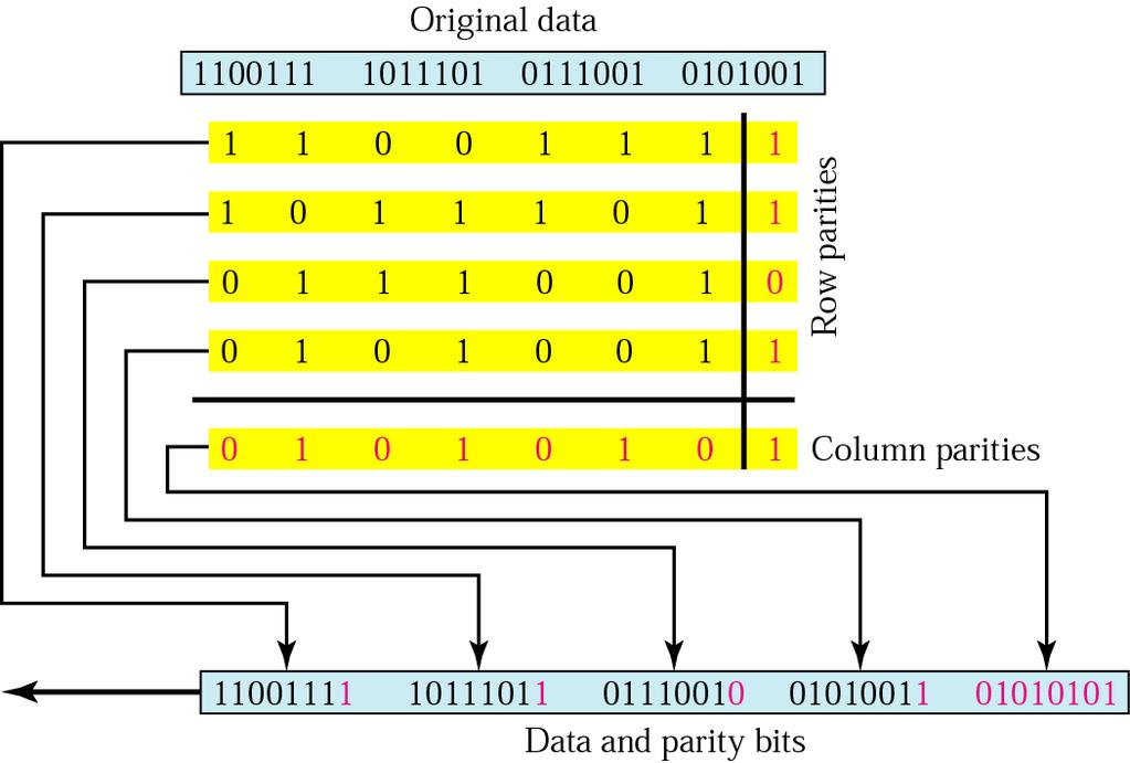
30 Two-dimensional parity-check code In two-dimensional parity check, a block of bits is divided into rows and a redundant row of bits is added to the whole block.

31 Two-dimensional parity-check code
32 Two-dimensional parity
33 Sent Received

34 Two-dimensional parity-check code

35 Two-dimensional parity-check code
36 Lecture 3 Error Detection and Correction
37 Hamming Code 1. Hamming codes provide for FEC using a Block Parity i.e, instead of one parity bit send a block of parity bits 2. Allows correction of single bit errors 3. This is accomplished by using more than one parity bit 4. Each computed on different combination of bits in the data Note: Study the Hamming code from the slides.
38 Redundancy Bits Calculation Parity Bits Decimal Binary Uses four (4) parity bits Bit Position 1 (r 1 ): Bits 3, 5, 7, 9, 11 Bit Position 2 (r 2 ): Bits 3, 6, 7, 10, 11 Bit Position 4 (r 3 ): Bits 5, 6, 7 Bit Position 8 (r 4 ): Bits 9, 10, 11
39 Redundancy Bits Calculation Position 1: check 1 bit, skip 1 bit,..etc. (1,3,5,7,9,11,13,15,...) Position 2: check 2 bits, skip 2 bits,..etc. (2,3,6,7,10,11,14,15,...) Position 4: check 4 bits, skip 4 bits,..etc. (4,5,6,7,12,13,14,15,20,21,22,23,...) Position 8: check 8 bits, skip 8 bits..etc. (8-15,24-31,40-47,...) Position 16: check 16 bits, skip 16 bits,..etc. (16-31,48-63,80-95,...)
40 Redundancy Bits Calculation
 So the sender will send")
41 Example Redundancy bits calculation using even-parity ( at the sender) So the sender will send
42 Error Correction using Hamming Code At the receiver: So the corrected data will be
43 Error Correction using Hamming Code Hamming code Increases overhead in both data transmitted and processing time

44 Burst error correction using Hamming code
45 Lecture 4 Cyclic codes
46 3.4 CYCLIC CODES In a cyclic code, if a codeword is cyclically shifted (rotated), the result is another codeword. Cyclic codes Cyclic Redundancy Check Checksum Topics discussed in this section: Cyclic Redundancy Check Generator and Checker Polynomials Checksum
47 CRC generator and checker

48 A CRC code with C(7, 4)
49 Binary Division Find the quotient and remainder when is divided by 1101 in modulo 2 arithmetic. As with traditional division, we note that the dividend is divisible once by the divisor. We place the divisor under the dividend and perform modulo 2 subtraction.
50 Binary Division Find the quotient and remainder when is divided by 1101 in modulo 2 arithmetic Now we bring down the next bit of the dividend. We see that is not divisible by So we place a zero in the quotient.
51 2.8 Binary Error Detection Division and Correction Find the quotient and remainder when is divided by 1101 in modulo 2 arithmetic 1010 is divisible by 1101 in modulo 2. We perform the modulo 2 subtraction.
52 2.8 Binary Error Detection Division and Correction Find the quotient and remainder when is divided by 1101 in modulo 2 arithmetic We find the quotient is 1011, and the remainder is This procedure is very useful to us in calculating CRC syndromes.
53 Division in CRC encoder
54 Division in the CRC decoder for two cases
55 At the sender side Suppose we want to transmit the information string: The receiver and sender decide to use the polynomial pattern, The information string is shifted left by one position less than the number of positions in the divisor. The remainder is found through modulo 2 division (at right) and added to the information string: =
56 At the receiver side If no bits are lost or corrupted, dividing the received information string by the agreed upon pattern will give a remainder of zero. We see this is so in the calculation at the right. Real applications use longer polynomials to cover larger information strings.

57 A polynomial to represent a binary word Note: The divisor 1101 corresponds to the polynomial: X 3 + X The divisor 1011 corresponds to the polynomial: X 3 + X
58 The divisor in a CRC is normally called the generator polynomial or simply the generator.
59 polynomial generator A good polynomial generator needs to have the following characteristics: 1. It should have at least two terms. 2. The coefficient of the term x 0 should be It should have the factor x + 1.
60 polynomial generator It is obvious that we cannot choose x (binary 10) or x 2 + x (binary 110) as the polynomial because both are divisible by x to guarantee that all burst errors of length degree of the polynomial are detected. However, we can choose x + 1 (binary 11) or x (binary 101) because it is divisible by x + 1 (binary division) to guarantee that all burst of odd numbers are detected.
61 Example 1 The CRC-12 x 12 + x 11 + x 3 + x + 1 which has a degree of 12, will detect all burst errors affecting an odd number of bits, will detect all burst errors with a length less than or equal to 12, and will detect, percent of the time, burst errors with a length of 12 or more.
62 If the generator has more than one term and the coefficient of x 0 is 1, all single errors can be caught. A generator that contains a factor of x + 1 can detect all odd-numbered errors.
63 Standard polynomials Name Polynomial Application CRC-8 x 8 + x 2 + x + 1 ATM header CRC-10 x 10 + x 9 + x 5 + x 4 + x ATM AAL CRC-16 (ITU-16) CRC-32 (ITU-32) x 16 + x 12 + x x 32 + x 26 + x 23 + x 22 + x 16 + x 12 + x 11 + x 10 + x 8 + x 7 + x 5 + x 4 + x 2 + x + 1 HDLC LANs
64 Lecture 5 Checksum
65 3.5 CHECKSUM Checksum is an error detection method. The checksum is used in the Internet by several protocols although not at the data link layer. However, we briefly discuss it here to complete our discussion on error checking Topics discussed in this section: Idea One s Complement Internet Checksum
66 CHECKSUM
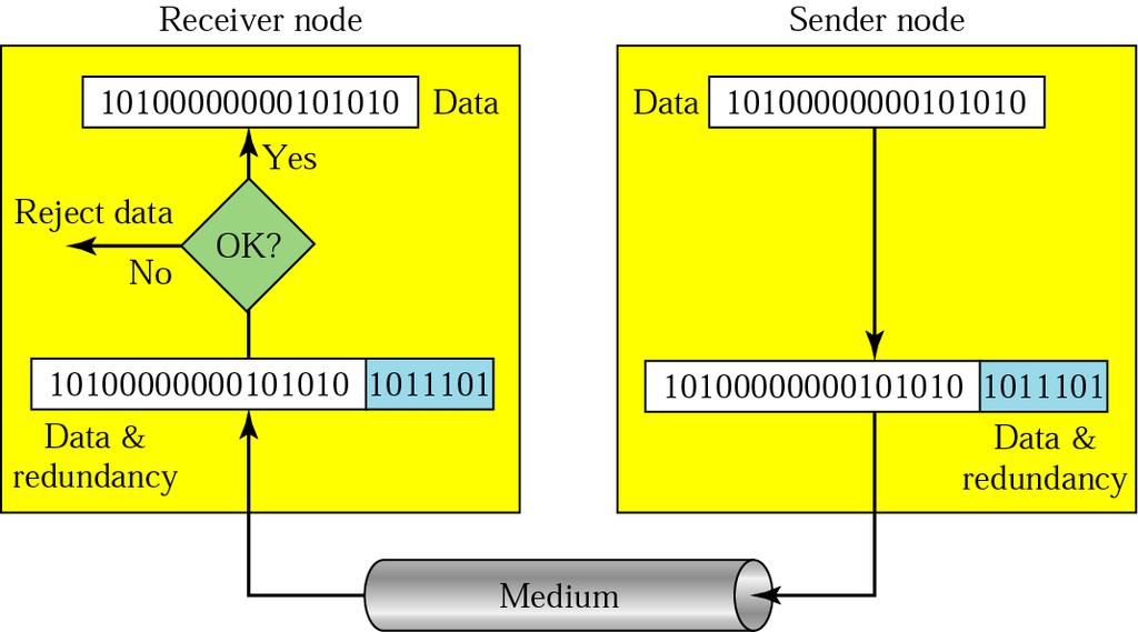
67 CHECKSUM The sender follows these steps: The unit is divided into k sections, each of n bits. All sections are added using one s complement to get the sum. The sum is complemented and becomes the checksum. The checksum is sent with the data.
68 CHECKSUM The receiver follows these steps: The unit is divided into k sections, each of n bits. All sections are added using one s complement to get the sum. The sum is complemented. If the result is zero, the data are accepted: otherwise, rejected.
69 Example 2 Suppose the following block of 16 bits is to be sent using a checksum of 8 bits The numbers are added using one s complement Sum Checksum The pattern sent is
70 Example 3 Now suppose the receiver receives the pattern sent in Example 2 and there is no error When the receiver adds the three sections, it will get all 1s, which, after complementing, is all 0s and shows that there is no error Sum Complement means that the pattern is OK.
71 Example 4 Now suppose there is a burst error of length 5 that affects 4 bits When the receiver adds the three sections, it gets Partial Sum Carry 1 Sum Complement the pattern is corrupted.
, we 0 1 1 0 1 0 0 1 1 1 1 1 0 0")
72 Example 5 If we need to send the set of numbers (7, 11, 12, 0, 6), we
73 An error-detecting code can detect only the types of errors for which it is designed; other types of errors may remain undetected.
74 Lecture 6 Flow Control
75 Data Link Layer (DLL)
76 Flow and Error Control The most important responsibilities of the data link layer are flow control and error control. Collectively, these functions are known as data link control. Flow control refers to a set of procedures used to restrict the amount of data that the sender can send before waiting for acknowledgment. Error control in the data link layer is based on automatic repeat request (ARQ), which is the retransmission of data.
77 Protocols
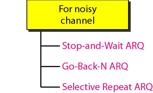
78 Noisy Channels We discuss three protocols in this section that use error control. Stop & Wait Automatic Repeat Request Go-Back-N Automatic Repeat Request Selective Repeat Automatic Repeat Request
79 Stop-and-Wait Automatic Repeat Request Simplest flow and error control mechanism The sending device keeps a copy of the last frame transmitted until it receives an acknowledgement Identification of duplicate transmission A damaged or lost frame is treated in the same way at the receiver. A control variable is needed at both sides. Timers introduced at the sender side. Positive ACK sent only for frames received safe & sound to define the next expected frame.
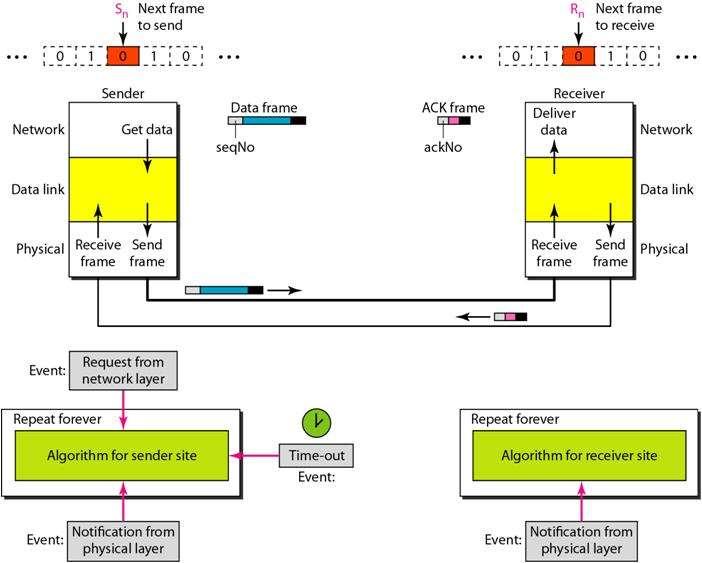
80 Stop-and-Wait
81 Stop-and-Wait ARQ Cases of operations: 1. Normal operation 2. The frame is lost 3. The ACK is lost 4. The ACK is delayed
82 Stop-and-Wait ARQ Normal operation The sender will not send the next piece of data until it is sure that the current one is correctly received sequence number is necessary to check for duplicated packets No NACK when packet is corrupted duplicate ACKs instead
83 Stop-and-Wait ARQ Lost or damaged frame A damaged or lost frame is treated in the same way at the receiver.
84 Stop-and-Wait ARQ Lost ACK Importance of frame numbering
85 Stop-and-Wait ARQ Delayed ACK Importance of ACK numbering
86 Duplex Stop-and-Wait ARQ Piggybacking combine data with ACK (less overhead saves bandwidth)
87 Efficiency The bandwidth-delay product defines the number of bits that can fill the link. bandwidth-delay product = Bandwidth * Delay.
88 Example Assume that, in a Stop-and-Wait ARQ system, the bandwidth of the line is 1 Mbps, and 1 bit takes 20 ms to make a round trip. What is the bandwidthdelay product? If the system data frames are 1000 bits in length, what is the utilization percentage of the link? Solution The bandwidth-delay product is the utilization percentage of the link is 1000/20,000 = 5%
89 Stop-and-Wait ARQ After each frame sent the host must wait for an ACK inefficient use of bandwidth To improve efficiency ACK should be sent after multiple frames Alternatives: Sliding Window protocols Go-back-N ARQ Selective Repeat ARQ
90 Lecture 7 Go-back-N
91 Pipelining One task begins before the other one ends increases efficiency in transmission There is no pipelining in Stop-and-Wait ARQ

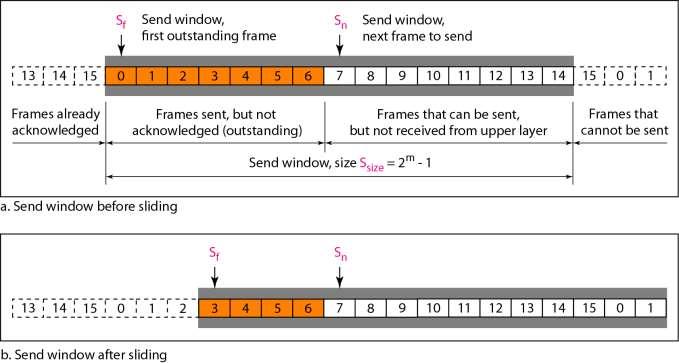
92 Sliding Window Protocols Sequence numbers Sent frames are numbered sequentially Sequence number is stored in the header if the number of bits to store the sequence number is m than sequence number goes from 0 to 2 m -1 sequence numbers Sliding window frame to hold the unacknowledged outstanding frames In Go-back-N ARQ the receiver window size always 1 acknowledged frames
93 Go-back-N Control variables S- holds the sequence number of the recently sent frame S F holds sequence number of the first frame in the window S L holds the sequence number of the last frame or S n holds the sequence number of the next frame to be send R sequence number of the frame expected to be received
94 Go-back-N
95 Go-back-N
96 The name of Go-back-N: why? Re-sending frame when the frame is damaged the sender goes back and resends a set of frames starting from the last one acknowledged; the number of retransmitted frames is N Example: The window size is 4. A sender has sent frame 6 and the timer expires for frame 3 (ACK3 is not received). The sender goes back and resends the frames 3, 4, 5 and 6.
97 Go-back-N normal operation How many frames can be transmitted without acknowledgment? ACK1 not necessary if ACK2 is sent Cumulative ACK expected sequence number
98 Go-back-N damaged or lost frame Damaged frames are discarded! Why are correctly received out of order packets are not buffered? What is the disadvantage of this?
99 Go-back-N sender window size sequence number
100 In the Go-Back-N Protocol, the sequence numbers are modulo 2 m, where m is the size of the sequence number field in bits (Number of bits needed to represent one sequence number).
101 Example What is the utilization percentage of the link in Example 11.4 if we have a protocol that can send up to 15 frames before stopping and worrying about the acknowledgments? Solution The bandwidth-delay product is still 20,000 bits. The system can send up to 15 frames or 15,000 bits during a round trip. This means the utilization is 15,000/20,000, or 75%. Of course, if there are damaged frames, the utilization percentage is much less because frames have to be resent.
102 Go-back-N Inefficient all out of order received packets are discarded This is a problem in a noisy link many frames must be retransmitted -> bandwidth consuming Solution re-send only the damaged frames Selective Repeat ARQ avoid unnecessary retransmissions
103 Stop-and-Wait ARQ is a special case of Go-Back-N ARQ in which the size of the send window is 1.
104 Lecture 8 Selective Repeat
105 Selective Repeat ARQ Processing at the receiver more complex The window size is reduced to one half of 2 m Both the transmitter and the receiver have the same window size Receiver expects frames within the range of the sequence numbers
106 Selective Repeat ARQ Sender window size Receive window size

107 Selective Repeat ARQ
108 Selective Repeat ARQ lost frame Note: retransmission triggered with NACK and not with expired timer.
109 Selective Repeat ARQ Sender window size

110 Piggybacking To improve the efficiency of the bidirectional protocols Piggybacking in Go-Back-N ARQ

111 Lecture 9 High-level Data Link Control
112 HDLC High-level Data Link Control (HDLC) supports halfduplex and full-duplex communication over pointto-point and multipoint links. It implements the ARQ mechanisms we discussed in this chapter. Topics discussed in this section: Configurations and Transfer Modes Normal respond mode (NRM) Asynchronous balanced mode (ABM) Frames Control Field
113 Normal response mode

114 Asynchronous balanced mode (ABM) ABM is used over point-to-point links.
115 Frames HDLC frames: 1. Information frames (I-frame). 2. Supervisory frames (S-frame). 3. Unnumbered frames (U-frame).

116 Frames HDLC frames
117 Frames HDLC frames 1. Flag: 8-bit ; that identifies the beginning and end of the frame 2. FCS: frame check sequence is error detection field 3. Address: contain the address of the secondary station. It can be one byte or more. If the address is more than one bytes, all bytes end with zero except the last byte ends with ones.

118 Control field format for the different frame types
: the value of ACK when piggybacking is used. P/F: (poll/final)")
119 Control field format for the I-frame N(s): Sequence number of the frame in travel N(R): the value of ACK when piggybacking is used. P/F: (poll/final)

120 Control field format for S-frame S S 1. SS=00 RR - Receiver Ready to accept more I-frames 2. SS=01 REJ - Go-Back-N retransmission request for an I-frame 3. SS=10 RNR - Receiver Not Ready to accept more I- frames 4. SS=11 SREJ - Selective retransmission request for an I-frame

121 U-frame control command and response
122 Example The figure in the next slide shows an exchange using piggybacking. Node A begins the exchange of information with an I-frame numbered 0 followed by another I-frame numbered 1. Node B piggybacks its acknowledgment of both frames onto an I-frame of its own. Node B s first I-frame is also numbered 0 [N(S) field] and contains a 2 in its N(R) field, acknowledging the receipt of A s frames 1 and 0 and indicating that it expects frame 2 to arrive next. Node B transmits its second and third I-frames (numbered 1 and 2) before accepting further frames from node A.

123 Example of piggybacking without error
124 Its N(R) information, therefore, has not changed: B frames 1 and 2 indicate that node B is still expecting A s frame 2 to arrive next. Node A has sent all its data. Therefore, it cannot piggyback an acknowledgment onto an I-frame and sends an S-frame instead. The RR code indicates that A is still ready to receive. The number 3 in the N(R) field tells B that frames 0, 1, and 2 have all been accepted and that A is now expecting frame number 3.
125 Example The figure in the next slide shows an exchange in which a frame is lost. Node B sends three data frames (0, 1, and 2), but frame 1 is lost. When node A receives frame 2, it discards it and sends a REJ frame for frame 1. Note that the protocol being used is Go-Back-N with the special use of an REJ frame as a NAK frame. The NAK frame does two things here: It confirms the receipt of frame 0 and declares that frame 1 and any following frames must be resent. Node B, after receiving the REJ frame, resends frames 1 and 2. Node A acknowledges the receipt by sending an RR frame (ACK) with acknowledgment number 3.

126 Figure Example of piggybacking with error

127 Data Transparency Bit Stuffing

128 Bit Stuffing < 15 15
TYPES OF ERRORS. Data can be corrupted during transmission. Some applications require that errors be detected and corrected.
 Data can be corrupted during transmission. Some applications require that errors be detected and corrected. TYPES OF ERRORS There are two types of errors, 1. Single Bit Error The term single-bit error
DATA LINK LAYER UNIT 7.
 DATA LINK LAYER UNIT 7 1 Data Link Layer Design Issues: 1. Service provided to network layer. 2. Determining how the bits of the physical layer are grouped into frames (FRAMING). 3. Dealing with transmission
SRI RAMAKRISHNA INSTITUTE OF TECHNOLOGY DEPARTMENT OF INFORMATION TECHNOLOGY COMPUTER NETWORKS UNIT - II DATA LINK LAYER
 SRI RAMAKRISHNA INSTITUTE OF TECHNOLOGY DEPARTMENT OF INFORMATION TECHNOLOGY COMPUTER NETWORKS UNIT - II DATA LINK LAYER 1. What are the responsibilities of data link layer? Specific responsibilities of
The data link layer has a number of specific functions it can carry out. These functions include. Figure 2-1. Relationship between packets and frames.
 Module 2 Data Link Layer: - Data link Layer design issues - Error Detection and correction Elementary Data link protocols, Sliding window protocols- Basic Concept, One Bit Sliding window protocol, Concept
Advanced Computer Networks. Rab Nawaz Jadoon DCS. Assistant Professor COMSATS University, Lahore Pakistan. Department of Computer Science
 Advanced Computer Networks Rab Nawaz Jadoon Department of Computer Science DCS COMSATS Institute of Information Technology Assistant Professor COMSATS University, Lahore Pakistan Advanced Computer Networks
The Data Link Layer Chapter 3
 The Data Link Layer Chapter 3 Data Link Layer Design Issues Error Detection and Correction Elementary Data Link Protocols Sliding Window Protocols Example Data Link Protocols Revised: August 2011 & February
Chapter 11 Data Link Control 11.1
 Chapter 11 Data Link Control 11.1 Copyright The McGraw-Hill Companies, Inc. Permission required for reproduction or display. 11-1 1 FRAMING The data link layer needs to pack bits into frames,, so that
Department of Computer and IT Engineering University of Kurdistan. Data Communication Netwotks (Graduate level) Data Link Layer
 Data Link Layer") Department of Computer and IT Engineering University of Kurdistan Data Communication Netwotks (Graduate level) Data Link Layer By: Dr. Alireza Abdollahpouri Data Link Layer 2 Data Link Layer Application
Department of Computer and IT Engineering University of Kurdistan Data Communication Netwotks (Graduate level) Data Link Layer By: Dr. Alireza Abdollahpouri Data Link Layer 2 Data Link Layer Application
Chapter 11 Data Link Control 11.1
 Chapter 11 Data Link Control 11.1 Copyright The McGraw-Hill Companies, Inc. Permission required for reproduction or display. 11-1 FRAMING The data link layer needs to pack bits into frames, so that each
PART III. Data Link Layer MGH T MGH C I 204
 PART III Data Link Layer Position of the data-link layer Data link layer duties LLC and MAC sublayers IEEE standards for LANs Chapters Chapter 10 Error Detection and Correction Chapter 11 Data Link Control
Data link layer functions. 2 Computer Networks Data Communications. Framing (1) Framing (2) Parity Checking (1) Error Detection
 Framing (2) Parity Checking (1) Error Detection") 2 Computer Networks Data Communications Part 6 Data Link Control Data link layer functions Framing Needed to synchronise TX and RX Account for all bits sent Error control Detect and correct errors Flow
2 Computer Networks Data Communications Part 6 Data Link Control Data link layer functions Framing Needed to synchronise TX and RX Account for all bits sent Error control Detect and correct errors Flow
ERROR AND FLOW CONTROL. Lecture: 10 Instructor Mazhar Hussain
 ERROR AND FLOW CONTROL Lecture: 10 Instructor Mazhar Hussain 1 FLOW CONTROL Flow control coordinates the amount of data that can be sent before receiving acknowledgement It is one of the most important
I. INTRODUCTION. each station (i.e., computer, telephone, etc.) directly connected to all other stations
 directly connected to all other stations") I. INTRODUCTION (a) Network Topologies (i) point-to-point communication each station (i.e., computer, telephone, etc.) directly connected to all other stations (ii) switched networks (1) circuit switched
I. INTRODUCTION (a) Network Topologies (i) point-to-point communication each station (i.e., computer, telephone, etc.) directly connected to all other stations (ii) switched networks (1) circuit switched
Chapter 11 Data Link Control 11.1
 Chapter 11 Data Link Control 11.1 Copyright The McGraw-Hill Companies, Inc. Permission required for reproduction or display. 11-1 FRAMING The data link layer needs to pack bits into frames, so that each
Flow control: Ensuring the source sending frames does not overflow the receiver
 Layer 2 Technologies Layer 2: final level of encapsulation of data before transmission over a physical link responsible for reliable transfer of frames between hosts, hop by hop, i.e. on a per link basis
CSMC 417. Computer Networks Prof. Ashok K Agrawala Ashok Agrawala. Nov 1,
 CSMC 417 Computer Networks Prof. Ashok K Agrawala 2018 Ashok Agrawala 1 Message, Segment, Packet, and Frame host host HTTP HTTP message HTTP TCP TCP segment TCP router router IP IP packet IP IP packet
The Data Link Layer Chapter 3
 The Data Link Layer Chapter 3 Data Link Layer Design Issues Error Detection and Correction Elementary Data Link Protocols Sliding Window Protocols Example Data Link Protocols Revised: August 2011 The Data
3. Data Link Layer 3-2
 3. Data Link Layer 3.1 Transmission Errors 3.2 Error Detecting and Error Correcting Codes 3.3 Bit Stuffing 3.4 Acknowledgments and Sequence Numbers 3.5 Flow Control 3.6 Examples: HDLC, PPP 3. Data Link
CS 640 Introduction to Computer Networks. Role of data link layer. Today s lecture. Lecture16
 Introduction to Computer Networks Lecture16 Role of data link layer Service offered by layer 1: a stream of bits Service to layer 3: sending & receiving frames To achieve this layer 2 does Framing Error
CS254 Network Technologies. Lecture 2: Network Models & Error Detection and Correction. Dr Nikos Antonopoulos
 CS254 Network Technologies Lecture 2: Network Models & Error Detection and Correction Dr Nikos Antonopoulos Department of Computing University of Surrey Autumn 2006 2.1 Layered Tasks Sender, Receiver,
INTERNET ARCHITECTURE & PROTOCOLS
 INTERNET ARCHITECTURE & PROTOCOLS Set # 02 Delivered By: Engr Tahir Niazi Need for Data Link Layer possibility of transmission errors receiver need to regulate the rate at which data arrive that's why
Data Link Layer. Learning Objectives. Position of the data-link layer. MCA 207, Data Communication & Networking
 Data Link Layer Bharati Vidyapeeth s Institute of Computer Applications and Management,New Delhi-63 by Vishal Jain U2. 1 Learning Objectives To introduce the design issues of data link layer. To discuss
Data Link Control. Claude Rigault ENST Claude Rigault, ENST 11/3/2002. Data Link control 1
 Data Link Control Claude Rigault ENST claude.rigault@enst.fr Data Link control Data Link Control Outline General principles of Data Link Control HDLC Data Link control 2 General principles of Data Link
William Stallings Data and Computer Communications. Chapter 7 Data Link Control
 William Stallings Data and Computer Communications Chapter 7 Data Link Control Flow Control Ensuring the sending entity does not overwhelm the receiving entity Preventing buffer overflow Transmission time
Ch. 7 Error Detection and Correction
 Ch. 7 Error Detection and Correction Error Detection and Correction Data can be corrupted during transmission. Some applications require that errors be detected and corrected. 2 1. Introduction Let us
 ET3110 Networking and Communications UNIT 2: Communication Techniques and Data Link Control Protocol skong@itt-tech.edutech.edu Learning Objectives Identify methods of detecting errors. Use Hamming code
Chapter 5 Data-Link Layer: Wired Networks
 Sungkyunkwan University Chapter 5 Data-Link Layer: Wired Networks Prepared by Syed M. Raza and H. Choo 2018-Fall Computer Networks Copyright 2000-2018 Networking Laboratory Chapter 5 Outline 5.1 Introduction
Data Link Control Protocols
 Data Link Control Protocols need layer of logic above Physical to manage exchange of data over a link frame synchronization flow control error control addressing control and data link management Flow Control
UNIT-II 1. Discuss the issues in the data link layer. Answer:
 UNIT-II 1. Discuss the issues in the data link layer. Answer: Data Link Layer Design Issues: The data link layer has a number of specific functions it can carry out. These functions include 1. Providing
Chapter 10 Error Detection and Correction. Copyright The McGraw-Hill Companies, Inc. Permission required for reproduction or display.
 Chapter 10 Error Detection and Correction 0. Copyright The McGraw-Hill Companies, Inc. Permission required for reproduction or display. Note The Hamming distance between two words is the number of differences
Chapter 3. The Data Link Layer
 Chapter 3 The Data Link Layer 1 Data Link Layer Algorithms for achieving reliable, efficient communication between two adjacent machines. Adjacent means two machines are physically connected by a communication
Telecom Systems Chae Y. Lee. Contents. Flow Control Error Detection/Correction Link Control (Error Control) Link Performance (Utility)
 Link Performance (Utility)") Data Link Control Contents Flow Control Error Detection/Correction Link Control (Error Control) Link Performance (Utility) 2 Flow Control Flow control is a technique for assuring that a transmitting entity
Data Link Control Contents Flow Control Error Detection/Correction Link Control (Error Control) Link Performance (Utility) 2 Flow Control Flow control is a technique for assuring that a transmitting entity
Outline. EEC-484/584 Computer Networks. Data Link Layer Design Issues. Framing. Lecture 6. Wenbing Zhao Review.
 EEC-484/584 Computer Networks Lecture 6 wenbing@ieee.org (Lecture nodes are based on materials supplied by Dr. Louise Moser at UCSB and Prentice-Hall) Outline Review Data Link Layer Design Issues Error
COMPUTER NETWORKS UNIT-3
 COMPUTER NETWORKS UNIT-3 Syllabus: The Data Link Layer - Data Link Layer Design Issues, Services Provided to the Network Layer Framing Error Control Flow Control, Error Detection and Correction Error-Correcting
EITF25 Internet Techniques and Applications L3: Data Link layer. Stefan Höst
 EITF25 Internet Techniques and Applications L3: Data Link layer Stefan Höst Communication on physical layer To transmit on the physical medium use signals At each computer it can be seen as transmitting
4. Error correction and link control. Contents
 //2 4. Error correction and link control Contents a. Types of errors b. Error detection and correction c. Flow control d. Error control //2 a. Types of errors Data can be corrupted during transmission.
Chapter 7: Data Link Control. Data Link Control Protocols
 Chapter 7: Data Link Control CS420/520 Axel Krings Page 1 Data Link Control Protocols Need layer of logic above Physical to manage exchange of data over a link frame synchronization flow control error
Chapter 7: Data Link Control. CS420/520 Axel Krings Page 1
 Chapter 7: Data Link Control CS420/520 Axel Krings Page 1 Data Link Control Protocols Need layer of logic above Physical to manage exchange of data over a link frame synchronization flow control error
Advanced Computer Networks. Rab Nawaz Jadoon DCS. Assistant Professor COMSATS University, Lahore Pakistan. Department of Computer Science
 Advanced Computer Networks Department of Computer Science DCS COMSATS Institute of Information Technology Rab Nawaz Jadoon Assistant Professor COMSATS University, Lahore Pakistan Advanced Computer Networks
CSE 461: Framing, Error Detection and Correction
 CSE 461: Framing, Error Detection and Correction Next Topics Framing Focus: How does a receiver know where a message begins/ends Error detection and correction Focus: How do we detect and correct messages
(Sicherungsschicht) Chapter 5 (part 2) [Wa0001] HDLC - 1.
![(Sicherungsschicht) Chapter 5 (part 2) [Wa0001] HDLC - 1.](/thumbs/74/71111055.jpg "(Sicherungsschicht) Chapter 5 (part 2) [Wa0001] HDLC - 1.") Data Link Layer (cont.) (Sicherungsschicht) Chapter 5 (part 2) [Wa0001] HDLC - 1 LOGICAL LINK CONTROL MEDIUM ACCESS CONTROL PHYSICAL SIGNALING DATA LINK LAYER PHYSICAL LAYER ACCESS UNIT INTERFACE PHYSICAL
Data Link Layer (cont.) (Sicherungsschicht) Chapter 5 (part 2) [Wa0001] HDLC - 1 LOGICAL LINK CONTROL MEDIUM ACCESS CONTROL PHYSICAL SIGNALING DATA LINK LAYER PHYSICAL LAYER ACCESS UNIT INTERFACE PHYSICAL
Data Link Layer (cont.) ( h h h ) (Sicherungsschicht) HDLC - 1.
 ( h h h ) (Sicherungsschicht) HDLC - 1.") Data Link Layer (cont.) ( h h h ) (Sicherungsschicht) HDLC - 1 LOGICAL L LINK CONTROL MEDIUM ACCESS CONTROL PHYSICAL SIGNALING DATA LINK LAYER PHYSICAL LAYER ACCESS UNIT INTERFACE PHYSICAL MEDIA ATTACHMENT
Data Link Layer (cont.) ( h h h ) (Sicherungsschicht) HDLC - 1 LOGICAL L LINK CONTROL MEDIUM ACCESS CONTROL PHYSICAL SIGNALING DATA LINK LAYER PHYSICAL LAYER ACCESS UNIT INTERFACE PHYSICAL MEDIA ATTACHMENT
2.1 CHANNEL ALLOCATION 2.2 MULTIPLE ACCESS PROTOCOLS Collision Free Protocols 2.3 FDDI 2.4 DATA LINK LAYER DESIGN ISSUES 2.5 FRAMING & STUFFING
 UNIT-2 2.1 CHANNEL ALLOCATION 2.2 MULTIPLE ACCESS PROTOCOLS 2.2.1 Pure ALOHA 2.2.2 Slotted ALOHA 2.2.3 Carrier Sense Multiple Access 2.2.4 CSMA with Collision Detection 2.2.5 Collision Free Protocols 2.2.5.1
Lecture 4: CRC & Reliable Transmission. Lecture 4 Overview. Checksum review. CRC toward a better EDC. Reliable Transmission
 1 Lecture 4: CRC & Reliable Transmission CSE 123: Computer Networks Chris Kanich Quiz 1: Tuesday July 5th Lecture 4: CRC & Reliable Transmission Lecture 4 Overview CRC toward a better EDC Reliable Transmission
CS321: Computer Networks Error Detection and Correction
 CS321: Computer Networks Error Detection and Correction Dr. Manas Khatua Assistant Professor Dept. of CSE IIT Jodhpur E-mail: manaskhatua@iitj.ac.in Error Detection and Correction Objective: System must
CSE 123: Computer Networks
 Student Name: PID: UCSD email: CSE 123: Computer Networks Homework 1 Solution (Due 10/12 in class) Total Points: 30 Instructions: Turn in a physical copy at the beginning of the class on 10/10. Problems:
CSMC 417. Computer Networks Prof. Ashok K Agrawala Ashok Agrawala Set 4. September 09 CMSC417 Set 4 1
 CSMC 417 Computer Networks Prof. Ashok K Agrawala 2009 Ashok Agrawala Set 4 1 The Data Link Layer 2 Data Link Layer Design Issues Services Provided to the Network Layer Framing Error Control Flow Control
Chapter 10 Error Detection and Correction 10.1
 Chapter 10 Error Detection and Correction 10.1 10-1 INTRODUCTION some issues related, directly or indirectly, to error detection and correction. Topics discussed in this section: Types of Errors Redundancy
The flow of data must not be allowed to overwhelm the receiver
 Data Link Layer: Flow Control and Error Control Lecture8 Flow Control Flow and Error Control Flow control refers to a set of procedures used to restrict the amount of data that the sender can send before
2.4 Error Detection Bit errors in a frame will occur. How do we detect (and then. (or both) frames contains an error. This is inefficient (and not
 frames contains an error. This is inefficient (and not") CS475 Networks Lecture 5 Chapter 2: Direct Link Networks Assignments Reading for Lecture 6: Sections 2.6 2.8 Homework 2: 2.1, 2.4, 2.6, 2.14, 2.18, 2.31, 2.35. Due Thursday, Sept. 15 2.4 Error Detection
CS475 Networks Lecture 5 Chapter 2: Direct Link Networks Assignments Reading for Lecture 6: Sections 2.6 2.8 Homework 2: 2.1, 2.4, 2.6, 2.14, 2.18, 2.31, 2.35. Due Thursday, Sept. 15 2.4 Error Detection
Data and Computer Communications
 Data and Computer Communications Chapter 7 Data Link Control Protocols Eighth Edition by William Stallings Lecture slides by Lawrie Brown Data Link Control Protocols "Great and enlightened one," said Ten-teh,
CS422 Computer Networks
 CS422 Computer Networks Lecture 3 Data Link Layer Dr. Xiaobo Zhou Department of Computer Science CS422 DataLinkLayer.1 Data Link Layer Design Issues Services Provided to the Network Layer Provide service
06/05/2008. Chapter 3. The Data Link Layer. Data Link Layer Design Issues. Services Provided to the Network Layer. Error Control Flow Control
 Chapter 3 The Data Link Layer Data Link Layer Design Issues Services Provided to the Network Layer Framing Error Control Flow Control 1 Functions of the Data Link Layer Provide service interface to the
Data Link Technology. Suguru Yamaguchi Nara Institute of Science and Technology Department of Information Science
 Data Link Technology Suguru Yamaguchi Nara Institute of Science and Technology Department of Information Science Agenda Functions of the data link layer Technologies concept and design error control flow
Inst: Chris Davison
 ICS 153 Introduction to Computer Networks Inst: Chris Davison cbdaviso@uci.edu ICS 153 Data Link Layer Contents Simplex and Duplex Communication Frame Creation Flow Control Error Control Performance of
Chapter Six. Errors, Error Detection, and Error Control. Data Communications and Computer Networks: A Business User s Approach Seventh Edition
 Chapter Six Errors, Error Detection, and Error Control Data Communications and Computer Networks: A Business User s Approach Seventh Edition After reading this chapter, you should be able to: Identify
Lecture 5. Homework 2 posted, due September 15. Reminder: Homework 1 due today. Questions? Thursday, September 8 CS 475 Networks - Lecture 5 1
 Lecture 5 Homework 2 posted, due September 15. Reminder: Homework 1 due today. Questions? Thursday, September 8 CS 475 Networks - Lecture 5 1 Outline Chapter 2 - Getting Connected 2.1 Perspectives on Connecting
Data Link Layer. Overview. Links. Shivkumar Kalyanaraman
 Data Link Layer shivkuma@ecse.rpi.edu http://www.ecse.rpi.edu/homepages/shivkuma 1-1 Based in part upon the slides of Prof. Raj Jain (OSU) Overview The data link layer problem Error detection and correction
Data Link Layer. Srinidhi Varadarajan
 Data Link Layer Srinidhi Varadarajan Data Link Layer: Functionality The data link layer must: Detect errors (using redundancy bits) Request retransmission if data is lost (using automatic repeat request
EE 122: Error detection and reliable transmission. Ion Stoica September 16, 2002
 EE 22: Error detection and reliable transmission Ion Stoica September 6, 2002 High Level View Goal: transmit correct information Problem: bits can get corrupted - Electrical interference, thermal noise
Jaringan Komputer. Data Link Layer. The Data Link Layer. Study the design principles
 Jaringan Komputer The Data Link Layer Data Link Layer Study the design principles Algorithms for achieving reliable, efficient communication between two adjacent machines at the data link layer Adjacent
High Level View. EE 122: Error detection and reliable transmission. Overview. Error Detection
 High Level View EE 22: Error detection and reliable transmission Ion Stoica September 6, 22 Goal: transmit correct information Problem: bits can get corrupted - Electrical interference, thermal noise Solution
Data Link Layer (part 2)
") Data Link Layer (part 2)! Question - What is a major disadvantage of asynchronous transmission? Reference: Chapters 6 and 7 Stallings Study Guide 6! Question - What is a major disadvantage of asynchronous
Data Link Layer (part 2)! Question - What is a major disadvantage of asynchronous transmission? Reference: Chapters 6 and 7 Stallings Study Guide 6! Question - What is a major disadvantage of asynchronous
Lecture 6: Reliable Transmission. CSE 123: Computer Networks Alex Snoeren (guest lecture) Alex Sn
 Alex Sn") Lecture 6: Reliable Transmission CSE 123: Computer Networks Alex Snoeren (guest lecture) Alex Sn Lecture 6 Overview Finishing Error Detection Cyclic Remainder Check (CRC) Handling errors Automatic Repeat
Lecture 6: Reliable Transmission CSE 123: Computer Networks Alex Snoeren (guest lecture) Alex Sn Lecture 6 Overview Finishing Error Detection Cyclic Remainder Check (CRC) Handling errors Automatic Repeat
Transmission SIGNALs
 Chapter 6 Digital Communications Basics 6.1 Introduction 6.2 Transmission media 6.3 Source of signal impairment 6.4 Asynchronous Transmission 6.5 Synchronous Transmission 6.6 Error Detection Methods 6.7
Error Detection Codes. Error Detection. Two Dimensional Parity. Internet Checksum Algorithm. Cyclic Redundancy Check.
 Error Detection Two types Error Detection Codes (e.g. CRC, Parity, Checksums) Error Correction Codes (e.g. Hamming, Reed Solomon) Basic Idea Add redundant information to determine if errors have been introduced
Data Link Control Protocols
 Protocols : Introduction to Data Communications Sirindhorn International Institute of Technology Thammasat University Prepared by Steven Gordon on 23 May 2012 Y12S1L07, Steve/Courses/2012/s1/its323/lectures/datalink.tex,
CS 4453 Computer Networks Winter
 CS 4453 Computer Networks Chapter 2 OSI Network Model 2015 Winter OSI model defines 7 layers Figure 1: OSI model Computer Networks R. Wei 2 The seven layers are as follows: Application Presentation Session
CMSC 2833 Lecture 18. Parity Add a bit to make the number of ones (1s) transmitted odd.
 transmitted odd.") Parity Even parity: Odd parity: Add a bit to make the number of ones (1s) transmitted even. Add a bit to make the number of ones (1s) transmitted odd. Example and ASCII A is coded 100 0001 Parity ASCII
Parity Even parity: Odd parity: Add a bit to make the number of ones (1s) transmitted even. Add a bit to make the number of ones (1s) transmitted odd. Example and ASCII A is coded 100 0001 Parity ASCII
Data Link Layer (1) Networked Systems 3 Lecture 6
 Networked Systems 3 Lecture 6") Data Link Layer (1) Networked Systems 3 Lecture 6 Purpose of Data Link Layer Arbitrate access to the physical layer Structure and frame the raw bits Provide flow control Detect and correct bit errors Perform
Data Link Layer (1) Networked Systems 3 Lecture 6 Purpose of Data Link Layer Arbitrate access to the physical layer Structure and frame the raw bits Provide flow control Detect and correct bit errors Perform
Overview. Data Link Technology. Role of the data-link layer. Role of the data-link layer. Function of the physical layer
 Overview Data Link Technology Functions of the data link layer Technologies concept and design error control flow control fundamental protocols Suguru Yamaguchi Nara Institute of Science and Technology
16.682: Communication Systems Engineering. Lecture 17. ARQ Protocols
 16.682: Communication Systems Engineering Lecture 17 ARQ Protocols Eytan Modiano Automatic repeat request (ARQ) Break large files into packets FILE PKT H PKT H PKT H Check received packets for errors Use
COMPUTER NETWORKS UNIT I. 1. What are the three criteria necessary for an effective and efficient networks?
 Question Bank COMPUTER NETWORKS Short answer type questions. UNIT I 1. What are the three criteria necessary for an effective and efficient networks? The most important criteria are performance, reliability
Analyzation of Automatic Repeat Request (ARQ) Protocols
 Protocols") RESEARCH ARTICLE OPEN ACCESS Analyzation of Automatic Repeat Request (ARQ) Protocols 1 Jeshvina.S, 2 Sneha.P, 3 Saraanya.S Final year BCA, Dept of Computer Science New Horizon College Kasturinagar, Bangalore
RESEARCH ARTICLE OPEN ACCESS Analyzation of Automatic Repeat Request (ARQ) Protocols 1 Jeshvina.S, 2 Sneha.P, 3 Saraanya.S Final year BCA, Dept of Computer Science New Horizon College Kasturinagar, Bangalore
Computer Network : Lecture Notes Nepal Engineering College Compiled by: Junior Professor: Daya Ram Budhathoki Nepal Engineering college, Changunarayan
 Computer Network : Lecture Notes Nepal Engineering College Compiled by: Junior Professor: Daya Ram Budhathoki Nepal Engineering college, Changunarayan Chapter: 6 Data Link layer: Services and Data Link
(Refer Slide Time: 2:20)
") Data Communications Prof. A. Pal Department of Computer Science & Engineering Indian Institute of Technology, Kharagpur Lecture-15 Error Detection and Correction Hello viewers welcome to today s lecture
Data Communications Prof. A. Pal Department of Computer Science & Engineering Indian Institute of Technology, Kharagpur Lecture-15 Error Detection and Correction Hello viewers welcome to today s lecture
CSE123A discussion session
 CSE123A discussion session 2007/02/02 Ryo Sugihara Review Data Link layer (1): Overview Sublayers End-to-end argument Framing sublayer How to delimit frame» Flags and bit stuffing Topics Data Link Layer
The Data Link Layer. Data Link Layer Design Issues
 The Data Link Layer Chapter 3 Data Link Layer Design Issues Network layer services Framing Error control Flow control 1 Packets and Frames Relationship between packets and frames. Network Layer Services
Lecture 2 Error Detection & Correction. Types of Errors Detection Correction
 Lecture 2 Error Detection & Correction Types of Errors Detection Correction Basic concepts Networks must be able to transfer data from one device to another with complete accuracy. Data can be corrupted
Data Link Control. Surasak Sanguanpong Last updated: 11 July 2000
 1/14 Data Link Control Surasak Sanguanpong nguan@ku.ac.th http://www.cpe.ku.ac.th/~nguan Last updated: 11 July 2000 Flow Control 2/14 technique for controlling the data transmission so that s have sufficient
DATA LINK LAYER: NEED
 Page no: 1 Department of Computer Science and Engineering CS6004 Computer Networking Subject Notes: UNIT-II DATA LINK LAYER: NEED Data Link Layer is second layer of OSI Layered Model. This layer is one
Networking Link Layer
 Networking Link Layer ECE 650 Systems Programming & Engineering Duke University, Spring 2018 (Link Layer Protocol material based on CS 356 slides) TCP/IP Model 2 Layer 1 & 2 Layer 1: Physical Layer Encoding
Announcements. No book chapter for this topic! Slides are posted online as usual Homework: Will be posted online Due 12/6
 Announcements No book chapter for this topic! Slides are posted online as usual Homework: Will be posted online Due 12/6 Copyright c 2002 2017 UMaine Computer Science Department 1 / 33 1 COS 140: Foundations
Chapter 3. The Data Link Layer
 Chapter 3 The Data Link Layer 1 Data Link Layer Design Issues Services Provided to the Network Layer Framing Error Control Flow Control 2 Functions of the Data Link Layer Provide service interface to the
No book chapter for this topic! Slides are posted online as usual Homework: Will be posted online Due 12/6
 Announcements No book chapter for this topic! Slides are posted online as usual Homework: Will be posted online Due 12/6 Copyright c 2002 2017 UMaine School of Computing and Information S 1 / 33 COS 140:
Lecture / The Data Link Layer: Framing and Error Detection
 Lecture 2 6.263/16.37 The Data Link Layer: Framing and Error Detection MIT, LIDS Slide 1 Data Link Layer (DLC) Responsible for reliable transmission of packets over a link Framing: Determine the start
Lecture 5: Data Link Layer Basics
 Lecture 5: Data Link Layer Basics Dr. Mohammed Hawa Electrical Engineering Department University of Jordan EE426: Communication Networks Layer 2 PDU: Frame 2 1 Bit-oriented vs. Byte-oriented Layer 2 protocols
C08a: Data Link Protocols
 CISC 7332X T6 C08a: Data Link Protocols Hui Chen Department of Computer & Information Science CUNY Brooklyn College 10/16/2018 CUNY Brooklyn College 1 Data Link Layer Responsible for delivering frames
Lecture 5: Flow Control. CSE 123: Computer Networks Alex C. Snoeren
 Lecture 5: Flow Control CSE 123: Computer Networks Alex C. Snoeren Pipelined Transmission Sender Receiver Sender Receiver Ignored! Keep multiple packets in flight Allows sender to make efficient use of
This Lecture. BUS Computer Facilities Network Management. Line Discipline. Data Link Layer
 This Lecture US35 - Computer Facilities Network Management Synchronisation and interfacing insufficient by themselves. Need to provide: Flow control - allow the receiver to regulate the flow of data. Error
Protocol Principles. Framing, FCS and ARQ 2005/03/11. (C) Herbert Haas
 Herbert Haas") Protocol Principles Framing, FCS and ARQ (C) Herbert Haas 2005/03/11 Link Layer Tasks Framing Frame Protection Optional Addressing Optional Error Recovery Connection-oriented or connectionless mode Optional
Protocol Principles Framing, FCS and ARQ (C) Herbert Haas 2005/03/11 Link Layer Tasks Framing Frame Protection Optional Addressing Optional Error Recovery Connection-oriented or connectionless mode Optional
CSCI-1680 Link Layer I Rodrigo Fonseca
 CSCI-1680 Link Layer I Rodrigo Fonseca Based partly on lecture notes by David Mazières, Phil Levis, John Jannotti Last time Physical layer: encoding, modulation Today Link layer framing Getting frames
CEG3185 TUT6. Prepared by Zhenxia Zhang Revisited by Jiying Zhao
 CEG3185 TUT6 Prepared by Zhenxia Zhang Revisited by Jiying Zhao HDLC High Level Data Link Control (HDLC) is a bit oriented synchronous data link layer protocol developed by the International Organization
Politecnico di Milano Scuola di Ingegneria Industriale e dell Informazione. Link Layer. Fundamentals of Communication Networks
 Politecnico di Milano Scuola di Ingegneria Industriale e dell Informazione Link Layer Fundamentals of Communication Networks Data Link layer o It is the first logical layer in the protocol stack o Functions
Introduction to Computer Networks. 03 Data Link Layer Introduction
 Introduction to Computer Networks 03 Data Link Layer Introduction Link Layer 1 Introduction and services 2 Link Layer Services 2.1 Framing 2.2 Error detection and correction 2.3 Flow Control 2.4 Multiple
CHANNEL CODING 1. Introduction
 CHANNEL CODING 1. Introduction The fundamental resources at the disposal of a communications engineer are signal power, time and bandwidth. For a given communications environment, these three resources
Point-to-Point Links. Outline Encoding Framing Error Detection Sliding Window Algorithm. Fall 2004 CS 691 1
 Point-to-Point Links Outline Encoding Framing Error Detection Sliding Window Algorithm Fall 2004 CS 691 1 Encoding Signals propagate over a physical medium modulate electromagnetic waves e.g., vary voltage
OSI Reference Model. Application Layer. Presentation Layer. Session Layer. Chapter 4: Application Protocols. Transport Layer.
 Chapter 2: Computer Networks 2.1: Physical Layer: representation of digital signals 2.2: Data Link Layer: error protection and access control 2.3: Network infrastructure 2.4 2.5: Local Area Network examples
Communication Networks. Part I
 Communication Networks Part I Manuel P. Ricardo Faculdade de Engenharia da Universidade do Porto » What are the main uses of computer networks?» What are the common architectures of network applications?»
Links. CS125 - mylinks 1 1/22/14
 Links 1 Goals of Today s Lecture Link-layer services Encoding, framing, and error detection Error correction and flow control Sharing a shared media Channel partitioning Taking turns Random access Shared