Data Link Layer. Learning Objectives. Position of the data-link layer. MCA 207, Data Communication & Networking
|
|
|
- Flora Lane
- 5 years ago
- Views:
Transcription


1 Data Link Layer Bharati Vidyapeeth s Institute of Computer Applications and Management,New Delhi-63 by Vishal Jain U2. 1 Learning Objectives To introduce the design issues of data link layer. To discuss different error control methods and flow control protocols To discuss protocols of medium access control sublayer To discuss Ethernet and Wireless Lan s s To discuss Bluetooth Bharati Vidyapeeth s Institute of Computer Applications and Management, New Delhi-63 by Vishal Jain U2.2 Position of the data-link layer Bharati Vidyapeeth s Institute of Computer Applications and Management, New Delhi-63 by Vishal Jain U2.3 Bharati Vidyapeeth s Institute of Computer Applications and Management, Delhi-63 by Vishal Jain U2. 1

2 Data Link Layer Duties Bharati Vidyapeeth s Institute of Computer Applications and Management, New Delhi-63 by Vishal Jain U2.4 LLC and MAC Sublayers Bharati Vidyapeeth s Institute of Computer Applications and Management, New Delhi-63 by Vishal Jain U2.5 IEEE standards for LANs Bharati Vidyapeeth s Institute of Computer Applications and Management, New Delhi-63 by Vishal Jain U2.6 Bharati Vidyapeeth s Institute of Computer Applications and Management, Delhi-63 by Vishal Jain U2. 2
3 Topics Error Detection and Correction Data Link Control and Protocols Multiple Access Local Area Networks Wireless LANs Switching Bharati Vidyapeeth s Institute of Computer Applications and Management, New Delhi-63 by Vishal Jain U2.7 Error Detection and Correction Bharati Vidyapeeth s Institute of Computer Applications and Management, New Delhi-63 by Vishal Jain U2.8 Learning Objectives To introduce the types of errors. To discuss different error detection methods. To discuss parity check, CRC and checksum. To discuss different error detection methods. Bharati Vidyapeeth s Institute of Computer Applications and Management, New Delhi-63 by Vishal Jain U2.9 Bharati Vidyapeeth s Institute of Computer Applications and Management, Delhi-63 by Vishal Jain U2. 3
4 Cont. Note: Data can be corrupted during transmission. For reliable communication, errors must be detected and corrected. Bharati Vidyapeeth s Institute of Computer Applications and Management, New Delhi-63 by Vishal Jain U2.10 Types of Error Single-Bit Error Burst Error Bharati Vidyapeeth s Institute of Computer Applications and Management, New Delhi-63 by Vishal Jain U2.11 Note: Cont. In a single-bit error, only one bit in the data unit has changed. Bharati Vidyapeeth s Institute of Computer Applications and Management, New Delhi-63 by Vishal Jain U2.12 Bharati Vidyapeeth s Institute of Computer Applications and Management, Delhi-63 by Vishal Jain U2. 4
5 Single-Bit Error Bharati Vidyapeeth s Institute of Computer Applications and Management, New Delhi-63 by Vishal Jain U2.13 Note: Cont. A burst error means that 2 or more bits in the data unit have changed. Bharati Vidyapeeth s Institute of Computer Applications and Management, New Delhi-63 by Vishal Jain U2.14 Burst Error of Length 5 Bharati Vidyapeeth s Institute of Computer Applications and Management, New Delhi-63 by Vishal Jain U2.15 Bharati Vidyapeeth s Institute of Computer Applications and Management, Delhi-63 by Vishal Jain U2. 5


6 Detection Redundancy Parity Check Cyclic Redundancy Check (CRC) Checksum Bharati Vidyapeeth s Institute of Computer Applications and Management, New Delhi-63 by Vishal Jain U2.16 Note: Cont. Error detection uses the concept of redundancy, which means adding extra bits for detecting errors at the destination. Bharati Vidyapeeth s Institute of Computer Applications and Management, New Delhi-63 by Vishal Jain U2.17 Redundancy Bharati Vidyapeeth s Institute of Computer Applications and Management, New Delhi-63 by Vishal Jain U2.18 Bharati Vidyapeeth s Institute of Computer Applications and Management, Delhi-63 by Vishal Jain U2. 6


.")
7 Detection Methods Bharati Vidyapeeth s Institute of Computer Applications and Management, New Delhi-63 by Vishal Jain U2.19 Even-Parity Concept Bharati Vidyapeeth s Institute of Computer Applications and Management, New Delhi-63 by Vishal Jain U2.20 Note: Cont. In parity check, a parity bit is added to every data unit so that the total number of 1s is even (or odd for odd-parity). Bharati Vidyapeeth s Institute of Computer Applications and Management, New Delhi-63 by Vishal Jain U2.21 Bharati Vidyapeeth s Institute of Computer Applications and Management, Delhi-63 by Vishal Jain U2. 7


8 Cont. Note: Simple parity check can detect all single-bit errors. It can detect burst errors only if the total number of errors in each data unit is odd. Bharati Vidyapeeth s Institute of Computer Applications and Management, New Delhi-63 by Vishal Jain U2.22 Two-Dimensional Parity Bharati Vidyapeeth s Institute of Computer Applications and Management, New Delhi-63 by Vishal Jain U2.23 Note: Cont. In two-dimensional parity check, a block of bits is divided into rows and a redundant row of bits is added to the whole block. Bharati Vidyapeeth s Institute of Computer Applications and Management, New Delhi-63 by Vishal Jain U2.24 Bharati Vidyapeeth s Institute of Computer Applications and Management, Delhi-63 by Vishal Jain U2. 8
9 CRC Generator and Checker Bharati Vidyapeeth s Institute of Computer Applications and Management, New Delhi-63 by Vishal Jain U2.25 Binary Division in a CRC Bharati Vidyapeeth s Institute of Computer Applications and Management, New Delhi-63 by Vishal Jain U2.26 Binary division in CRC checker Bharati Vidyapeeth s Institute of Computer Applications and Management, New Delhi-63 by Vishal Jain U2.27 Bharati Vidyapeeth s Institute of Computer Applications and Management, Delhi-63 by Vishal Jain U2. 9
10 A polynomial Bharati Vidyapeeth s Institute of Computer Applications and Management, New Delhi-63 by Vishal Jain U2.28 A Polynomial Representing a Divisor Bharati Vidyapeeth s Institute of Computer Applications and Management, New Delhi-63 by Vishal Jain U2.29 Cont. Table Standard polynomials Name Polynomial Application CRC-8 x 8 + x 2 + x + 1 ATM header CRC-10 x 10 + x 9 + x 5 + x 4 + x ATM AAL ITU-16 x 16 + x 12 + x HDLC ITU-32 x 32 + x 26 + x 23 + x 22 + x 16 + x 12 + x 11 + x 10 + x 8 + x 7 + x 5 + x 4 + x 2 + x + 1 LANs Bharati Vidyapeeth s Institute of Computer Applications and Management, New Delhi-63 by Vishal Jain U2.30 Bharati Vidyapeeth s Institute of Computer Applications and Management, Delhi-63 by Vishal Jain U2. 10


11 Checksum Bharati Vidyapeeth s Institute of Computer Applications and Management, New Delhi-63 by Vishal Jain U2.31 Data Unit and Checksum Bharati Vidyapeeth s Institute of Computer Applications and Management, New Delhi-63 by Vishal Jain U2.32 Note: Cont. The sender follows these steps: The unit is divided into k sections, each of n bits. All sections are added using one s complement to get the sum. The sum is complemented and becomes the checksum. The checksum is sent with the data. Bharati Vidyapeeth s Institute of Computer Applications and Management, New Delhi-63 by Vishal Jain U2.33 Bharati Vidyapeeth s Institute of Computer Applications and Management, Delhi-63 by Vishal Jain U2. 11
12 Cont. Note: The receiver follows these steps: The unit is divided into k sections, each of n bits. All sections are added using one s complement to get the sum. The sum is complemented. If the result is zero, the data are accepted: otherwise, rejected. Bharati Vidyapeeth s Institute of Computer Applications and Management, New Delhi-63 by Vishal Jain U2.34 Cont. Suppose the following block of 16 bits is to be sent using a checksum of 8 bits The numbers are added using one s complement Sum Checksum The pattern sent is Bharati Vidyapeeth s Institute of Computer Applications and Management, New Delhi-63 by Vishal Jain U2.35 Cont. Now suppose the receiver receives the pattern sent in Example 7 and there is no error When the receiver adds the three sections, it will get all 1s, which, after complementing, is all 0s and shows that there is no error Sum Complement means that the pattern is OK. Bharati Vidyapeeth s Institute of Computer Applications and Management, New Delhi-63 by Vishal Jain U2.36 Bharati Vidyapeeth s Institute of Computer Applications and Management, Delhi-63 by Vishal Jain U2. 12
13 Cont. Now suppose there is a burst error of length 5 that affects 4 bits When the receiver adds the three sections, it gets Partial Sum Carry 1 Sum Complement the pattern is corrupted. Bharati Vidyapeeth s Institute of Computer Applications and Management, New Delhi-63 by Vishal Jain U2.37 Cont. Table 10.2 Data and redundancy bits Number of data bits m Number of redundancy bits r Total bits m + r Bharati Vidyapeeth s Institute of Computer Applications and Management, New Delhi-63 by Vishal Jain U2.38 Positions of Redundancy Bits Bharati Vidyapeeth s Institute of Computer Applications and Management, New Delhi-63 by Vishal Jain U2.39 Bharati Vidyapeeth s Institute of Computer Applications and Management, Delhi-63 by Vishal Jain U2. 13


14 Redundancy Bits Calculation Bharati Vidyapeeth s Institute of Computer Applications and Management, New Delhi-63 by Vishal Jain U2.40 Example of Redundancy Bharati Vidyapeeth s Institute of Computer Applications and Management, New Delhi-63 by Vishal Jain U2.41 Error Detection using Hamming Bharati Vidyapeeth s Institute of Computer Applications and Management, New Delhi-63 by Vishal Jain U2.42 Bharati Vidyapeeth s Institute of Computer Applications and Management, Delhi-63 by Vishal Jain U2. 14

15 Burst Error Correction Example Bharati Vidyapeeth s Institute of Computer Applications and Management, New Delhi-63 by Vishal Jain U2.43 Conclusion Errors can be single bit or burst errors Three common redundancy methods are parity check, CRC and checksum Errors can be corrected by retransmission Hamming code is error correction through retransmission Bharati Vidyapeeth s Institute of Computer Applications and Management, New Delhi-63 by Vishal Jain U2.44 Topic Data Link Control and Protocols Bharati Vidyapeeth s Institute of Computer Applications and Management, New Delhi-63 by Vishal Jain U2.45 Bharati Vidyapeeth s Institute of Computer Applications and Management, Delhi-63 by Vishal Jain U2. 15
16 Learning Objectives To introduce the protocols for error and flow control. To discuss Stop and wait, Go back N and selective repear ARQ To discuss concept of piggybacking and pipelining To discuss HDLC protocol and its various frames Bharati Vidyapeeth s Institute of Computer Applications and Management, New Delhi-63 by Vishal Jain U2.46 Note: Cont. Flow control refers to a set of procedures used to restrict the amount of data that the sender can send before waiting for acknowledgment. Bharati Vidyapeeth s Institute of Computer Applications and Management, New Delhi-63 by Vishal Jain U2.47 Note: Cont. Error control in the data link layer is based on automatic repeat request, which is the retransmission of data. Bharati Vidyapeeth s Institute of Computer Applications and Management, New Delhi-63 by Vishal Jain U2.48 Bharati Vidyapeeth s Institute of Computer Applications and Management, Delhi-63 by Vishal Jain U2. 16
17 Cont. Error Control Techniques When an error is detected in a message, the receiver sends a request to the transmitter to retransmit the ill-fated message or packet. The most popular retransmission scheme is known as Automatic- Repeat-Request (ARQ). Such schemes, where receiver asks transmitter to re-transmit if it detects an error, are known as reverse error correction techniques. Bharati Vidyapeeth s Institute of Computer Applications and Management, New Delhi-63 by Vishal Jain U2.49 Cont. Bharati Vidyapeeth s Institute of Computer Applications and Management, New Delhi-63 by Vishal Jain U2.50 Normal Operation Bharati Vidyapeeth s Institute of Computer Applications and Management, New Delhi-63 by Vishal Jain U2.51 Bharati Vidyapeeth s Institute of Computer Applications and Management, Delhi-63 by Vishal Jain U2. 17
18 Cont. In Stop-and-Wait ARQ, which is simplest among all protocols, the sender (say station A) transmits a frame and then waits till it receives positive acknowledgement (ACK) or negative acknowledgement (NACK) from the receiver (say station B). Station B sends an ACK if the frame is received correctly, otherwise it sends NACK. Station A sends a new frame after receiving ACK; otherwise it retransmits the old frame, if it receives a NACK. Bharati Vidyapeeth s Institute of Computer Applications and Management, New Delhi-63 by Vishal Jain U2.52 Stop-and-Wait ARQ, Lost Frame Bharati Vidyapeeth s Institute of Computer Applications and Management, New Delhi-63 by Vishal Jain U2.53 Stop-and-Wait ARQ, Lost ACK Bharati Vidyapeeth s Institute of Computer Applications and Management, New Delhi-63 by Vishal Jain U2.54 Bharati Vidyapeeth s Institute of Computer Applications and Management, Delhi-63 by Vishal Jain U2. 18
19 Cont. Note: In Stop-and-Wait ARQ, numbering frames prevents the retaining of duplicate frames. Bharati Vidyapeeth s Institute of Computer Applications and Management, New Delhi-63 by Vishal Jain U2.55 Stop-and-Wait, Delayed ACK Bharati Vidyapeeth s Institute of Computer Applications and Management, New Delhi-63 by Vishal Jain U2.56 Note: Cont. Numbered acknowledgments are needed if an acknowledgment is delayed and the next frame is lost. Bharati Vidyapeeth s Institute of Computer Applications and Management, New Delhi-63 by Vishal Jain U2.57 Bharati Vidyapeeth s Institute of Computer Applications and Management, Delhi-63 by Vishal Jain U2. 19
20 Piggy Backing Bharati Vidyapeeth s Institute of Computer Applications and Management, New Delhi-63 by Vishal Jain U2.58 Cont. What is piggybacking? What is its advantage? In practice, the link between receiver and transmitter is full duplex and usually both transmitter and receiver stations send data to each over. So, instead of sending separate acknowledgement packets, a portion (few bits) of the data frames can be used for acknowledgement. This phenomenon is known as piggybacking. The piggybacking helps in better channel utilization. Further, multi-frame acknowledgement can be done. Bharati Vidyapeeth s Institute of Computer Applications and Management, New Delhi-63 by Vishal Jain U2.59 Sender sliding Window Go Back N Bharati Vidyapeeth s Institute of Computer Applications and Management, New Delhi-63 by Vishal Jain U2.60 Bharati Vidyapeeth s Institute of Computer Applications and Management, Delhi-63 by Vishal Jain U2. 20

21 Receiver Sliding Window Bharati Vidyapeeth s Institute of Computer Applications and Management, New Delhi-63 by Vishal Jain U2.61 Control Variables Bharati Vidyapeeth s Institute of Computer Applications and Management, New Delhi-63 by Vishal Jain U2.62 Cont. The most popular ARQ protocol is the go-back-n ARQ, where the sender sends the frames continuously without waiting for acknowledgement. That is why it is also called as continuous ARQ. As the receiver receives the frames, it keeps on sending ACKs or a NACK, in case a frame is incorrectly received. When the sender receives a NACK, it retransmits the frame in error plus all the succeeding frames as shown in Fig.. Hence, the name of the protocol is go-back-n ARQ. If a frame is lost, the receiver sends NAK after receiving the next frame Bharati Vidyapeeth s Institute of Computer Applications and Management, New Delhi-63 by Vishal Jain U2.63 Bharati Vidyapeeth s Institute of Computer Applications and Management, Delhi-63 by Vishal Jain U2. 21


22 Go-Back-N, Normal Operation Bharati Vidyapeeth s Institute of Computer Applications and Management, New Delhi-63 by Vishal Jain U2.64 Go-Back-N, Lost Frame Bharati Vidyapeeth s Institute of Computer Applications and Management, New Delhi-63 by Vishal Jain U2.65 Go-Back-N : Sender Window Size Bharati Vidyapeeth s Institute of Computer Applications and Management, New Delhi-63 by Vishal Jain U2.66 Bharati Vidyapeeth s Institute of Computer Applications and Management, Delhi-63 by Vishal Jain U2. 22

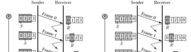
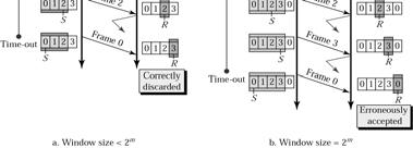
23 Cont. Note: In Go-Back-N ARQ, the size of the sender window must be less than 2m; the size of the receiver window is always 1. Bharati Vidyapeeth s Institute of Computer Applications and Management, New Delhi-63 by Vishal Jain U2.67 Cont. The selective-repetitive ARQ scheme retransmits only those for which NAKs are received or for which timer has expired, this is shown in the Fig This is the most efficient among the ARQ schemes, but the sender must be more complex so that it can send out-of-order frames. The receiver also must have storage space to store the post-nak frames and processing power to reinsert frames in proper sequence. Bharati Vidyapeeth s Institute of Computer Applications and Management, New Delhi-63 by Vishal Jain U2.68 Selective Repeat Bharati Vidyapeeth s Institute of Computer Applications and Management, New Delhi-63 by Vishal Jain U2.69 Bharati Vidyapeeth s Institute of Computer Applications and Management, Delhi-63 by Vishal Jain U2. 23

24 Selective Repeat, Lost Frame Bharati Vidyapeeth s Institute of Computer Applications and Management, New Delhi-63 by Vishal Jain U2.70 Note: Cont. In Selective Repeat ARQ, the size of the sender and receiver window must be at most one-half of 2 m. Bharati Vidyapeeth s Institute of Computer Applications and Management, New Delhi-63 by Vishal Jain U2.71 Selective Repeat Bharati Vidyapeeth s Institute of Computer Applications and Management, New Delhi-63 by Vishal Jain U2.72 Bharati Vidyapeeth s Institute of Computer Applications and Management, Delhi-63 by Vishal Jain U2. 24
25 Selective Repeat How the inefficiency of Stop-and-Wait protocol is overcome in sliding window protocol? The Stop-and-Wait protocol is inefficient when large numbers of small packets are send by the transmitter since the transmitter has to wait for the acknowledgement of each individual packet before sending the next one. This problem can be overcome by sliding window protocol. In sliding window protocol multiple frames (up to a fixed number of frames) are send before receiving an acknowledgement from the receiver. Bharati Vidyapeeth s Institute of Computer Applications and Management, New Delhi-63 by Vishal Jain U2.73 HDLC HDLC is a bit-oriented protocol. It was developed by the International Organization for Standardization (ISO). It falls under the ISO standards ISO 3309 and ISO It has found itself being used throughout the world. It has been so widely implemented because it supports both half-duplex and fullduplex communication lines, point-to-point (peer to peer) and multi-point networks, and switched or non-switched channels. HDLC supports several modes of operation, including a simple sliding-window mode for reliable delivery. Bharati Vidyapeeth s Institute of Computer Applications and Management, New Delhi-63 by Vishal Jain U2.74 HDLC HDLC specifies the following three types of stations for data link control: Primary Station Secondary Station Combined Station Bharati Vidyapeeth s Institute of Computer Applications and Management, New Delhi-63 by Vishal Jain U2.75 Bharati Vidyapeeth s Institute of Computer Applications and Management, Delhi-63 by Vishal Jain U2. 25
26 HDLC Primary Station Within a network using HDLC as its data link protocol, if a configuration is used in which there is a primary station, it is used as the controlling station on the link. It has the responsibility of controlling all other stations on the link (usually secondary stations). primary issues commadnds and secondary issues responses. Despite this important aspect of being on the link, the primary station is also responsible for the organization of data flow on the link. It also takes care of error recovery at the data link level (layer 2 of the OSI model). Bharati Vidyapeeth s Institute of Computer Applications and Management, New Delhi-63 by Vishal Jain U2.76 Secondary Station HDLC If the data link protocol being used is HDLC, and a primary station is present, a secondary station must also be present on the data link. The secondary station is under the control of the primary station. It has no ability, or direct responsibility for controlling the link. It is only activated when requested by the primary station. It only responds to the primary station. The secondary station's frames are called responses. It can only send response frames when requested by the primary station. A primary station maintains a separate logical link with each secondary station. Bharati Vidyapeeth s Institute of Computer Applications and Management, New Delhi-63 by Vishal Jain U2.77 Combined Station HDLC A combined station is a combination of a primary and secondary station. On the link, all combined stations are able to send and receive commands and responses without any permission from any other stations on the link. HDLC also defines three types of configurations for the three types of stations. The word configuration refers to the relationship between the hardware devices on a link. Bharati Vidyapeeth s Institute of Computer Applications and Management, New Delhi-63 by Vishal Jain U2.78 Bharati Vidyapeeth s Institute of Computer Applications and Management, Delhi-63 by Vishal Jain U2. 26
27 HDLC Following are the three configurations defined by HDLC: Unbalanced Configuration Balanced Configuration Symmetrical Configuration The unbalanced configuration in an HDLC link consists of a primary station and one or more secondary stations. The unbalanced condition arises because one station controls the other stations. The balanced configuration in an HDLC link consists of two or more combined stations. Each of the stations has equal and complimentary responsibility compared to each other. Bharati Vidyapeeth s Institute of Computer Applications and Management, New Delhi-63 by Vishal Jain U2.79 HDLC This third type of configuration is not widely in use today. It consists of two independent point-to-point to Bharati Vidyapeeth s Institute of Computer Applications and Management, New Delhi-63 by Vishal Jain U2.80 HDLC HDLC Operational Modes A mode in HDLC is the relationship between two devices involved in an exchange; the mode describes who controls the link. Exchanges over unbalanced configurations are always conducted in normal response mode. Exchanges over symmetric or balanced configurations can be set to specific mode using a frame design to deliver the command. HDLC offers three different modes of operation. These three modes of operations are: Normal Response Mode (NRM) Asynchronous Response Mode (ARM) Asynchronous Balanced Mode (ABM) Bharati Vidyapeeth s Institute of Computer Applications and Management, New Delhi-63 by Vishal Jain U2.81 Bharati Vidyapeeth s Institute of Computer Applications and Management, Delhi-63 by Vishal Jain U2. 27

28 HDLC Normal Response Mode This is the mode in which the primary station initiates transfers to the secondary station. The secondary station can only transmit a response when, and only when, it is instructed to do so by the primary station. In other words, the secondary station must receive explicit permission from the primary station to transfer a response. After receiving permission from the primary station, the secondary station initiates its transmission. Bharati Vidyapeeth s Institute of Computer Applications and Management, New Delhi-63 by Vishal Jain U2.82 HDLC This transmission from the secondary station to the primary station may be much more than just an acknowledgment of a frame. It may in fact be more than one information frame. Once the last frame is transmitted by the secondary station, it must wait once again from explicit permission to transfer anything, from the primary station. Normal Response Mode is only used within an unbalanced configuration. Bharati Vidyapeeth s Institute of Computer Applications and Management, New Delhi-63 by Vishal Jain U2.83 NRM Bharati Vidyapeeth s Institute of Computer Applications and Management, New Delhi-63 by Vishal Jain U2.84 Bharati Vidyapeeth s Institute of Computer Applications and Management, Delhi-63 by Vishal Jain U2. 28
29 ARM Asynchronous Response Mode In this mode, the primary station doesn't initiate transfers to the secondary station. In fact, the secondary station does not have to wait to receive explicit permission from the primary station to transfer any frames. The frames may be more than just acknowledgment frames. They may contain data, or control information regarding the status of the secondary station. Bharati Vidyapeeth s Institute of Computer Applications and Management, New Delhi-63 by Vishal Jain U2.85 ARM This mode can reduce overhead on the link, as no frames need to be transferred in order to give the secondary station permission to initiate a transfer. However, some limitations do exist. Due to the fact that this mode is asynchronous, the secondary station must wait until it detects and idle channel before it can transfer any frames. This is when the ARM link is operating at half-duplex. Bharati Vidyapeeth s Institute of Computer Applications and Management, New Delhi-63 by Vishal Jain U2.86 SBM Synchronous Balanced Mode This mode is used in case of combined stations. There is no need for permission on the part of any station in this mode. This is because combined stations do not require any sort of instructions to perform any task on the link. Bharati Vidyapeeth s Institute of Computer Applications and Management, New Delhi-63 by Vishal Jain U2.87 Bharati Vidyapeeth s Institute of Computer Applications and Management, Delhi-63 by Vishal Jain U2. 29
30 ABM Bharati Vidyapeeth s Institute of Computer Applications and Management, New Delhi-63 by Vishal Jain U2.88 HDLC Frame Bharati Vidyapeeth s Institute of Computer Applications and Management, New Delhi-63 by Vishal Jain U2.89 HDLC Frame The Flag field Every frame on the link must begin and end with a flag sequence field (F). Stations attached to the data link must continually listen for a flag sequence. The flag sequence is an octet looking like Flags are continuously transmitted on the link between frames to keep the link active. Two other bit sequences are used in HDLC as signals for the stations on the link. These two bit sequences are: Seven 1's, but less than 15 signal an abort signal. The stations on the link know there is a problem on the link. 15 or more 1's indicate that the channel is in an idle state. Bharati Vidyapeeth s Institute of Computer Applications and Management, New Delhi-63 by Vishal Jain U2.90 Bharati Vidyapeeth s Institute of Computer Applications and Management, Delhi-63 by Vishal Jain U2. 30
31 HDLC Frame The Address field The address field (A) identifies the primary or secondary stations involvement in the frame transmission or reception. Each station on the link has a unique address. In an unbalanced configuration, the A field in both commands and responses refer to the secondary station. In a balanced configuration, the command frame contains the destination station address and the response frame has the sending station's address. Bharati Vidyapeeth s Institute of Computer Applications and Management, New Delhi-63 by Vishal Jain U2.91 The Control field HDLC Frame HDLC uses the control field (C) to determine how to control the communications process. This field contains the commands, responses and sequences numbers used to maintain the data flow accountability of the link, defines the functions of the frame and initiates the logic to control the movement of traffic between sending and receiving stations. Bharati Vidyapeeth s Institute of Computer Applications and Management, New Delhi-63 by Vishal Jain U2.92 There three control field formats: HDLC Frame Information Transfer Format: The frame is used to transmit enduser data between two devices. Supervisory Format: The control field performs control functions such as acknowledgment of frames, requests for re-transmission, and requests for temporary suspension of frames being transmitted. Its use depends on the operational mode being used. Unnumbered Format: This control field format is also used for control purposes. It is used to perform link initialization, link disconnection and other link control functions. Bharati Vidyapeeth s Institute of Computer Applications and Management, New Delhi-63 by Vishal Jain U2.93 Bharati Vidyapeeth s Institute of Computer Applications and Management, Delhi-63 by Vishal Jain U2. 31
32 HDLC Frame The Poll/Final Bit (P/F) The 5th bit position in the control field is called the poll/final bit, or P/F bit. It can only be recognized when it is set to 1. If it is set to 0, it is ignored. The poll/final bit is used to provide dialogue between the primary station and secondary station. The primary station uses P=1 to acquire a status response from the secondary station. The P bit signifies a poll. The secondary station responds to the P bit by transmitting a data or status frame to the primary station with the P/F bit set to F=1. The F bit can also be used to signal the end of a transmission from the secondary station under Normal Response Mode. Bharati Vidyapeeth s Institute of Computer Applications and Management, New Delhi-63 by Vishal Jain U2.94 The Information field or Data field HDLC Frame This field is not always present in a HDLC frame. It is only present when the Information Transfer Format is being used in the control field. The information field contains the actually data the sender is transmitting to the receiver in an I-Frame and network management information in U-Frame. The Frame check Sequence field This field contains a 16-bit, or 32-bit cyclic redundancy check bits. Bharati Vidyapeeth s Institute of Computer Applications and Management, New Delhi-63 by Vishal Jain U2.95 HDLC Commands and Responses HDLC Frame Information transfer format command and response (I- Frame) The function of the information command and response is to transfer sequentially numbered frames, each containing an information field, across the data link. Bharati Vidyapeeth s Institute of Computer Applications and Management, New Delhi-63 by Vishal Jain U2.96 Bharati Vidyapeeth s Institute of Computer Applications and Management, Delhi-63 by Vishal Jain U2. 32
33 HDLC Frame Supervisory format command and responses (S-Frame) Supervisory (S) commands and responses are used to perform numbered supervisory functions such as acknowledgment, polling, temporary suspension of information transfer, or error recovery. Frames with the S format control field cannot contain an information field. A primary station may use the S format command frame with the P bit set to 1 to request a response from a secondary station regarding its status. Bharati Vidyapeeth s Institute of Computer Applications and Management, New Delhi-63 by Vishal Jain U2.97 HDLC Frame Format commands and responses are as follows: Receive Ready (RR) is used by the primary or secondary station to indicate that it is ready to receive an information frame and/or acknowledge previously received frames. Receive Not Ready (RNR) is used to indicate that the primary or secondary station is not ready to receive any information frames or acknowledgments. Bharati Vidyapeeth s Institute of Computer Applications and Management, New Delhi-63 by Vishal Jain U2.98 HDLC Frame Format commands and responses are as follows: Reject (REJ) is used to request the retransmission of frames. Selective Reject (SREJ) is used by a station to request retransmission of specific frames. An SREJ must be transmitted for each erroneous frame; each frame is treated as a separate error. Only one SREJ can remain outstanding on the link at any one time. Bharati Vidyapeeth s Institute of Computer Applications and Management, New Delhi-63 by Vishal Jain U2.99 Bharati Vidyapeeth s Institute of Computer Applications and Management, Delhi-63 by Vishal Jain U2. 33

 places the secondary station into NRM. NRM does not allow the secondary station to send any unsolicited frames.")
34 HDLC Frame Unnumbered Format Commands and responses (U-Frame) The unnumbered format commands and responses are used to extend the number of data link control functions. The unnumbered format frames have 5 modifier bits, which allow for up to 32 additional commands and 32 additional response functions. 13 command functions, and 8 response functions Bharati Vidyapeeth s Institute of Computer Applications and Management, New Delhi-63 by Vishal Jain U2.100 HDLC Frame Set Normal Response Mode (SNRM) places the secondary station into NRM. NRM does not allow the secondary station to send any unsolicited frames. Hence the primary station has control of the link. Set Asynchronous Response Mode (SARM) allows a secondary station to transmit frames without a poll from the primary station. Set Asynchronous Balanced Mode (SABM) sets the operational mode of the link to ABM. Disconnect (DISC) places the secondary station in to a disconnected mode. Bharati Vidyapeeth s Institute of Computer Applications and Management, New Delhi-63 by Vishal Jain U2.101 HDLC Frame Types Bharati Vidyapeeth s Institute of Computer Applications and Management, New Delhi-63 by Vishal Jain U2.102 Bharati Vidyapeeth s Institute of Computer Applications and Management, Delhi-63 by Vishal Jain U2. 34

35 I-frame Bharati Vidyapeeth s Institute of Computer Applications and Management, New Delhi-63 by Vishal Jain U2.103 S-Frame Control field in HDLC Bharati Vidyapeeth s Institute of Computer Applications and Management, New Delhi-63 by Vishal Jain U2.104 Cont. Bharati Vidyapeeth s Institute of Computer Applications and Management, New Delhi-63 by Vishal Jain U2.105 Bharati Vidyapeeth s Institute of Computer Applications and Management, Delhi-63 by Vishal Jain U2. 35
 Set asynchronous balanced mode Set asynchronous balanced mode (extended) Unnumbered poll Unnumbered information Unnumbered acknowledgment")


36 Cont. Command/response SNRM SNRME SABM SABME UP UI UA RD DISC DM RIM SIM RSET XID FRMR Meaning Set normal response mode Set normal response mode (extended) Set asynchronous balanced mode Set asynchronous balanced mode (extended) Unnumbered poll Unnumbered information Unnumbered acknowledgment Request disconnect Disconnect Disconnect mode Request information mode Set initialization mode Reset Exchange ID Frame reject Bharati Vidyapeeth s Institute of Computer Applications and Management, New Delhi-63 by Vishal Jain U2.106 Bit Stuffing and Removal Bharati Vidyapeeth s Institute of Computer Applications and Management, New Delhi-63 by Vishal Jain U2.107 Bit Stuffing in HDLC Bharati Vidyapeeth s Institute of Computer Applications and Management, New Delhi-63 by Vishal Jain U2.108 Bharati Vidyapeeth s Institute of Computer Applications and Management, Delhi-63 by Vishal Jain U2. 36
37 Conclusion Flow control is the regulation of the sender s data so that receiver buffer does not become overwhelmed. Stop and Wait the sender sends a frame and waits for acknowledgment In Go back N and Selective Repeat multiple frames can be sent at the same time HDLC is a protocol that implements ARQ mechanisms Bharati Vidyapeeth s Institute of Computer Applications and Management, New Delhi-63 by Vishal Jain U2.109 TOPIC Multiple Access Bharati Vidyapeeth s Institute of Computer Applications and Management, New Delhi-63 by Vishal Jain U2.110 Switching When there are many devices, it is necessary to develop suitable mechanism for communication between any two devices. In the switched network methodology, the network consists of a set of interconnected nodes, among which information is transmitted from source to destination via different routes, which is controlled by the switching mechanism. Bharati Vidyapeeth s Institute of Computer Applications and Management, New Delhi-63 by Vishal Jain U2.111 Bharati Vidyapeeth s Institute of Computer Applications and Management, Delhi-63 by Vishal Jain U2. 37
38 Switching The end devices that wish to communicate with each other are called stations. The switching devices are called nodes. Some nodes connect to other nodes and some are to connected to some stations. The switching performed by different nodes can be categorized into the following three types: Circuit Switching Packet Switching Message Switching Bharati Vidyapeeth s Institute of Computer Applications and Management, New Delhi-63 by Vishal Jain U2.112 Circuit Switching Communication via circuit switching implies that there is a dedicated communication path between the two stations. The path is a connected through a sequence of links between network nodes. On each physical link, a logical channel is dedicated to the connection. Circuit switching is commonly used technique in telephony, where the caller sends a special message with the address of the callee (i.e. by dialing a number) to state its destination. Bharati Vidyapeeth s Institute of Computer Applications and Management, New Delhi-63 by Vishal Jain U2.113 Circuit Switching It involved the following three distinct steps: Circuit Establishment: To establish an end-to-end connection before any transfer of data. Some segments of the circuit may be a dedicated link, while some other segments may be shared. Data transfer: Transfer data is from the source to the destination. The data may be analog or digital, depending on the nature of the network. The connection is generally full-duplex. Bharati Vidyapeeth s Institute of Computer Applications and Management, New Delhi-63 by Vishal Jain U2.114 Bharati Vidyapeeth s Institute of Computer Applications and Management, Delhi-63 by Vishal Jain U2. 38
39 Circuit Switching Circuit disconnect: Terminate connection at the end of data transfer. Signals must be propagated to deallocate the dedicated resources. Thus the actual physical electrical path or circuit between the source and destination host must be established before the message is transmitted. This connection, once established, remains exclusive and continuous for the complete duration of information exchange and the circuit becomes disconnected only when the source wants to do so. Bharati Vidyapeeth s Institute of Computer Applications and Management, New Delhi-63 by Vishal Jain U2.115 Message Switching In this switching method, a different strategy is used, where instead of establishing a dedicated physical line between the sender and the receiver, the message is sent to the nearest directly connected switching node. This node stores the message, checks for errors, selects the best available route and forwards the message to the next intermediate node. Bharati Vidyapeeth s Institute of Computer Applications and Management, New Delhi-63 by Vishal Jain U2.116 Message Switching The line becomes free again for other messages, while the process is being continued in some other nodes. Due to the mode of action, this method is also known as storeand-forward technology where the message hops from node to node to its final destination. Each node stores the full message, checks for errors and forwards it. In this switching technique, more devices can share the network bandwidth, as compared with circuit switching technique. Bharati Vidyapeeth s Institute of Computer Applications and Management, New Delhi-63 by Vishal Jain U2.117 Bharati Vidyapeeth s Institute of Computer Applications and Management, Delhi-63 by Vishal Jain U2. 39
40 Message Switching Temporary storage of message reduces traffic congestion to some extent. Higher priority can be given to urgent messages, so that the low priority messages are delayed while the urgent ones are forwarded faster. Through broadcast addresses one message can be sent to several users. Last of all, since the destination host need not be active when the message is sent, message switching techniques improve global communications. Bharati Vidyapeeth s Institute of Computer Applications and Management, New Delhi-63 by Vishal Jain U2.118 Message Switching Each network node receives and stores the message Determines the next leg of the route, and Queues the message to go out on that link. Advantages: Line efficiency is greater (sharing of links). Data rate conversion is possible. Even under heavy traffic, packets are accepted, possibly with a greater delay in delivery. Message priorities can be used, to satisfy the requirements, if any. Disadvantages: Message of large size monopolizes the link and storage Bharati Vidyapeeth s Institute of Computer Applications and Management, New Delhi-63 by Vishal Jain U2.119 Packet Switching The basic approach is not much different from message switching. It is also based on the same store-andforward approach. However, to overcome the limitations of message switching, messages are divided into subsets of equal length called packets. In packet switching approach, data are transmitted in short packets (few Kbytes). A long message is broken up into a series of packets Bharati Vidyapeeth s Institute of Computer Applications and Management, New Delhi-63 by Vishal Jain U2.120 Bharati Vidyapeeth s Institute of Computer Applications and Management, Delhi-63 by Vishal Jain U2. 40
41 Packet Switching Main difference between Packet switching and Circuit Switching is that the communication lines are not dedicated to passing messages from the source to the destination. In Packet Switching, different messages (and even different packets) can pass through different routes, and when there is a "dead time" in the communication between the source and the destination, the lines can be used by other sources. Bharati Vidyapeeth s Institute of Computer Applications and Management, New Delhi-63 by Vishal Jain U2.121 Packet Switching Main difference between Packet switching and Circuit Switching is that the communication lines are not dedicated to passing messages from the source to the destination. In Packet Switching, different messages (and even different packets) can pass through different routes, and when there is a "dead time" in the communication between the source and the destination, the lines can be used by other sources. Bharati Vidyapeeth s Institute of Computer Applications and Management, New Delhi-63 by Vishal Jain U2.122 Packet Switching There are two basic approaches commonly used to packet Switching: virtual-circuit packet switching and datagram packet switching. In virtual-circuit packet switching a virtual circuit is made before actual data is transmitted, but it is different from circuit switching in a sense that in circuit switching the call accept signal comes only from the final destination to the source while in case of virtual-packet switching this call accept signal is transmitted between each adjacent intermediate node Bharati Vidyapeeth s Institute of Computer Applications and Management, New Delhi-63 by Vishal Jain U2.123 Bharati Vidyapeeth s Institute of Computer Applications and Management, Delhi-63 by Vishal Jain U2. 41
42 Packet Switching There are two basic approaches commonly used to packet Switching: virtual-circuit packet switching and datagram packet switching. In virtual-circuit packet switching a virtual circuit is made before actual data is transmitted, but it is different from circuit switching in a sense that in circuit switching the call accept signal comes only from the final destination to the source while in case of virtual-packet switching this call accept signal is transmitted between each adjacent intermediate node Bharati Vidyapeeth s Institute of Computer Applications and Management, New Delhi-63 by Vishal Jain U2.124 Packet Switching An initial setup phase is used to set up a route between the intermediate nodes for all the packets passed during the session between the two end nodes. In each intermediate node, an entry is registered in a table to indicate the route for the connection that has been set up. Thus, packets passed through this route, can have short headers, containing only a virtual circuit identifier (VCI), and not their destination. Each intermediate node passes the packets according to the information that was stored in it, in the setup phase. Bharati Vidyapeeth s Institute of Computer Applications and Management, New Delhi-63 by Vishal Jain U2.125 Packet Switching Datagram Packet Switching Networks This approach uses a different, more dynamic scheme, to determine the route through the network links. Each packet is treated as an independent entity, and its header contains full information about the destination of the packet. The intermediate nodes examine the header of the packet, and decide to which node to send the packet so that it will reach its destination. Bharati Vidyapeeth s Institute of Computer Applications and Management, New Delhi-63 by Vishal Jain U2.126 Bharati Vidyapeeth s Institute of Computer Applications and Management, Delhi-63 by Vishal Jain U2. 42
43 Packet Switching Thus, in this method, the packets don't follow a preestablished route, and the intermediate nodes (the routers) don't have pre-defined knowledge of the routes that the packets should be passed through. Packets can follow different routes to the destination, and delivery is not guaranteed (although packets usually do follow the same route, and are reliably sent). Bharati Vidyapeeth s Institute of Computer Applications and Management, New Delhi-63 by Vishal Jain U2.127 Packet Switching Due to the nature of this method, the packets can reach the destination in a different order than they were sent, thus they must be sorted at the destination to form the original message. This approach is time consuming since every router has to decide where to send each packet. The main implementation of Datagram Switching network is the Internet, which uses the IP network protocol. Bharati Vidyapeeth s Institute of Computer Applications and Management, New Delhi-63 by Vishal Jain U2.128 Packet Switching Advantages : Call setup phase is avoided (for transmission of a few packets, datagram will be faster). Because it is more primitive, it is more flexible. Congestion/failed link can be avoided (more reliable). Problems: Packets may be delivered out of order. If a node crashes momentarily, all of its queued packets are lost. Bharati Vidyapeeth s Institute of Computer Applications and Management, New Delhi-63 by Vishal Jain U2.129 Bharati Vidyapeeth s Institute of Computer Applications and Management, Delhi-63 by Vishal Jain U2. 43

.")
44 Switching Bharati Vidyapeeth s Institute of Computer Applications and Management, New Delhi-63 by Vishal Jain U2.130 Multiple-Access Protocols Bharati Vidyapeeth s Institute of Computer Applications and Management, New Delhi-63 by Vishal Jain U2.131 Random Access In random access or contention methods, no station is superior to another station and none is assigned the control over another. No station permits, or does not permit, another station to send. The decision to send data depends on the state of the medium (busy or idle). In random access method, each station has the right to the medium without being controlled by any other station. However, if more than one station tries to send, there is an access conflict- collision- and the frames will be either destroyed and modified. Bharati Vidyapeeth s Institute of Computer Applications and Management, New Delhi-63 by Vishal Jain U2.132 Bharati Vidyapeeth s Institute of Computer Applications and Management, Delhi-63 by Vishal Jain U2. 44


45 Random Access MA CSMA CSMA/CD CSMA/CA Bharati Vidyapeeth s Institute of Computer Applications and Management, New Delhi-63 by Vishal Jain U2.133 Random-access methods Bharati Vidyapeeth s Institute of Computer Applications and Management, New Delhi-63 by Vishal Jain U2.134 ALOHA network Bharati Vidyapeeth s Institute of Computer Applications and Management, New Delhi-63 by Vishal Jain U2.135 Bharati Vidyapeeth s Institute of Computer Applications and Management, Delhi-63 by Vishal Jain U2. 45
, but it can be used on anysharedmedium medium.")
46 ALOHA Network The ALOHA scheme was invented by Abramson in 1970 for a packet radio network connecting remote stations to a central computer and various data terminals at the campus of the university of Hawaii. It was designed for a radio (Wireless LAN), but it can be used on anysharedmedium medium. Users are allowed random access of the central computer through a common radio frequency band f1 and the computer centre broadcasts all received signals on a different frequency band f2. Bharati Vidyapeeth s Institute of Computer Applications and Management, New Delhi-63 by Vishal Jain U2.136 ALOHA network Pure ALOHA The original ALOHA protocol is called pure ALOHA. The idea is that each station sends a frame whenever it has a frame to send. However, since there is only one channel to share, there is the possibility of collision between frames from different stations. We need to mention that even if one bit of a frame coexists on the channel with one bit from another frame, there is collision and both will be destroyed. Bharati Vidyapeeth s Institute of Computer Applications and Management, New Delhi-63 by Vishal Jain U2.137 ALOHA Network Bharati Vidyapeeth s Institute of Computer Applications and Management, New Delhi-63 by Vishal Jain U2.138 Bharati Vidyapeeth s Institute of Computer Applications and Management, Delhi-63 by Vishal Jain U2. 46

47 ALOHA Network The pure ALOHA protocol relies on acknowledgment from the receiver. When a station sends a frame, it expects the receiver to send an acknowledgement. If the acknowledgment does not arrive after a time-out period, the station assumes that the frame has been destroyed and resends the frame. Bharati Vidyapeeth s Institute of Computer Applications and Management, New Delhi-63 by Vishal Jain U2.139 ALOHA network A collision involves two or more stations. If all these stations try to resend their frames after the time-out, the frame will collide again. Pure ALOHA dictates that when the time-out period passes, each station waits a random amount of time before resending its frame. The randomness will help avoid more collisions. We call this time the back-off time. Bharati Vidyapeeth s Institute of Computer Applications and Management, New Delhi-63 by Vishal Jain U2.140 Procedure for ALOHA protocol Bharati Vidyapeeth s Institute of Computer Applications and Management, New Delhi-63 by Vishal Jain U2.141 Bharati Vidyapeeth s Institute of Computer Applications and Management, Delhi-63 by Vishal Jain U2. 47

48 ALOHA Network Slotted ALOHA In slotted ALOHA we devide the time into slots and force the station to send only at the beginning of the time slot. Bharati Vidyapeeth s Institute of Computer Applications and Management, New Delhi-63 by Vishal Jain U2.142 Collision in CSMA The poor efficiency of the ALOHA scheme can be attributed to the fact that a node start transmission without paying any attention to what others are doing. In situations where propagation delay of the signal between two nodes is small compared to the transmission time of a packet, all other nodes will know very quickly when a node starts transmission. This observation is the basis of the carrier-sense multipleaccess (CSMA) protocol. Bharati Vidyapeeth s Institute of Computer Applications and Management, New Delhi-63 by Vishal Jain U2.143 Collision in CSMA In this scheme, a node having data to transmit first listens to the medium to check whether another transmission is in progress or not. The node starts sending only when the channel is free, that is there is no carrier. That is why the scheme is also known as listen-before-talk. talk. Bharati Vidyapeeth s Institute of Computer Applications and Management, New Delhi-63 by Vishal Jain U2.144 Bharati Vidyapeeth s Institute of Computer Applications and Management, Delhi-63 by Vishal Jain U2. 48
49 Collision in CSMA There are three variations of this basic scheme as outlined below. (i) 1-persistent CSMA: In this case, a node having data to send, start sending, if the channel is sensed free. If the medium is busy, the node continues to monitor until the channel is idle. Then it starts sending data. (ii) Non-persistent CSMA: If the channel is sensed free, the node starts sending the packet. Otherwise, the node waits for a random amount of time and then monitors the channel. (iii) p-persistent CSMA: If the channel is free, a node starts sending the packet. Otherwise the node continues to monitor until the channel is free and then it sends with probability p. Bharati Vidyapeeth s Institute of Computer Applications and Management, New Delhi-63 by Vishal Jain U2.145 Persistence Strategies Bharati Vidyapeeth s Institute of Computer Applications and Management, New Delhi-63 by Vishal Jain U2.146 Collision in CSMA Bharati Vidyapeeth s Institute of Computer Applications and Management, New Delhi-63 by Vishal Jain U2.147 Bharati Vidyapeeth s Institute of Computer Applications and Management, Delhi-63 by Vishal Jain U2. 49
 augments the algorithm to handle the collision.")

50 Persistence strategies Bharati Vidyapeeth s Institute of Computer Applications and Management, New Delhi-63 by Vishal Jain U2.148 CSMA/CD The CSMA method does not specify the procedure following a collision. Carrier sense multiple access with collision detection (CSMA/CD) augments the algorithm to handle the collision. In this method, a station monitors the medium after it sends a frame to see if the transmission was successful. If so, the station is finished.. If, however, there is a collision, the frame is sent again. Bharati Vidyapeeth s Institute of Computer Applications and Management, New Delhi-63 by Vishal Jain U2.149 CSMA/CD CSMA/CD protocol can be considered as a refinement over the CSMA scheme. It has evolved to overcome one glaring inefficiency of CSMA. In CSMA scheme, when two packets collide the channel remains unutilized for the entire duration of transmission time of both the packets. If the propagation time is small (which is usually the case) compared to the packet transmission time, wasted channel capacity can be considerable. Bharati Vidyapeeth s Institute of Computer Applications and Management, New Delhi-63 by Vishal Jain U2.150 Bharati Vidyapeeth s Institute of Computer Applications and Management, Delhi-63 by Vishal Jain U2. 50
51 CSMA/CD This wastage of channel capacity can be reduced if the nodes continue to monitor the channel while transmitting a packet and immediately cease transmission when collision is detected. This refined scheme is known as Carrier Sensed Multiple Access with Collision Detection (CSMA/CD) or Listen-While-Talk. Bharati Vidyapeeth s Institute of Computer Applications and Management, New Delhi-63 by Vishal Jain U2.151 CSMA/CD On top of the CSMA, the following rules are added to convert it into CSMA/CD: (i) If a collision is detected during transmission of a packet, the node immediately ceases transmission and it transmits jamming signal for a brief duration to ensure that all stations know that collision has occurred. (ii) After transmitting the jamming signal, the node waits for a random amount of time and then transmission is resumed. Bharati Vidyapeeth s Institute of Computer Applications and Management, New Delhi-63 by Vishal Jain U2.152 CSMA/CD The random delay ensures that the nodes, which were involved in the collision are not likely to have a collision at the time of retransmissions. To achieve stability in the back off scheme, a technique known as binary exponential back off is used. A node will attempt to transmit repeatedly in the face of repeated collisions, but after each collision, the mean value of the random delay is doubled. After 15 retries (excluding the original try), the unlucky packet is discarded and the node reports an error. Bharati Vidyapeeth s Institute of Computer Applications and Management, New Delhi-63 by Vishal Jain U2.153 Bharati Vidyapeeth s Institute of Computer Applications and Management, Delhi-63 by Vishal Jain U2. 51


52 CSMA/CD Collision of the first bit in CSMA/CD Bharati Vidyapeeth s Institute of Computer Applications and Management, New Delhi-63 by Vishal Jain U2.154 CSMA/CD Collision and abortion in CSMA/CD Bharati Vidyapeeth s Institute of Computer Applications and Management, New Delhi-63 by Vishal Jain U2.155 CSMA/CD procedure Bharati Vidyapeeth s Institute of Computer Applications and Management, New Delhi-63 by Vishal Jain U2.156 Bharati Vidyapeeth s Institute of Computer Applications and Management, Delhi-63 by Vishal Jain U2. 52
 can also be used to define the priority of a station or a frame.")
53 CSMA/CA procedure Carrier sense multiple access with collision avoidance (CSMA/CA) is CSMA with procedures that avoid a collision. In CSMA/CA, the IFS ( interframe space) can also be used to define the priority of a station or a frame. In CSMA/CA, if the station finds the channel busy, it does not restart the timer of the contention window; it stops the timer and restarts it when the channel becomes idle. Bharati Vidyapeeth s Institute of Computer Applications and Management, New Delhi-63 by Vishal Jain U2.157 CSMA/CA procedure Bharati Vidyapeeth s Institute of Computer Applications and Management, New Delhi-63 by Vishal Jain U2.158 Comparison How performance is improved in CSMA/CD protocol compared to CSMA protocol? In CSMA scheme, a station monitors the channel before sending a packet. Whenever a collision is detected, it does not stop transmission leading to some wastage of time. On the other hand, in CSMA/CD scheme, whenever a station detects a collision, it sends a jamming signal by which other station comes to know that a collision occurs. As a result, wastage of time is reduced leading to improvement in performance. Bharati Vidyapeeth s Institute of Computer Applications and Management, New Delhi-63 by Vishal Jain U2.159 Bharati Vidyapeeth s Institute of Computer Applications and Management, Delhi-63 by Vishal Jain U2. 53

54 Control Access Reservation Polling Token Passing Bharati Vidyapeeth s Institute of Computer Applications and Management, New Delhi-63 by Vishal Jain U2.160 Reservation access method In Reservation method, a station needs to make a reservation before sending data. Time to divided into intervals, a reservation frame precedes the data frame sent in that interval If there are N stations in the system, there are exactly N reservation minislots in the reservation frame. When a station needs to send a data frame, it makes a reservation in its own minislot. The station that have made reservations can send their data frames after the reservation frame. Bharati Vidyapeeth s Institute of Computer Applications and Management, New Delhi-63 by Vishal Jain U2.161 Reservation access method Bharati Vidyapeeth s Institute of Computer Applications and Management, New Delhi-63 by Vishal Jain U2.162 Bharati Vidyapeeth s Institute of Computer Applications and Management, Delhi-63 by Vishal Jain U2. 54


55 Polling Polling works with topologies in which one device is designated as primary station and the other devices are secondary stations. All data exchanges must be made through the primary device even when the ultimate destination is a secondary device. The primary device controls the link; the secondary devices follow its instructions. i It is up to the primary device to determine which device is allowed to use the channel at a given time. Bharati Vidyapeeth s Institute of Computer Applications and Management, New Delhi-63 by Vishal Jain U2.163 Select The select function is used whenever the primary device has something to send. The primary must alert the secondary to the upcoming transmission and wait for an ACK of the secondary ready status. Before sending the data, the primary creates and transmits a select (SEL) frame, one field of which includes the address of the intended secondary. Bharati Vidyapeeth s Institute of Computer Applications and Management, New Delhi-63 by Vishal Jain U2.164 Select Bharati Vidyapeeth s Institute of Computer Applications and Management, New Delhi-63 by Vishal Jain U2.165 Bharati Vidyapeeth s Institute of Computer Applications and Management, Delhi-63 by Vishal Jain U2. 55
 each device in turn if it has anything to send.")

56 Poll The poll function is used by the primary device to solicit information from the secondary devices. When the primary is ready to receive data, it must ask (poll) each device in turn if it has anything to send. When the first secondary is approached, it responds either with NAK frame if it has nothing to send. Or with data if it does. If the response is negative then primary asks to other secondary station. Bharati Vidyapeeth s Institute of Computer Applications and Management, New Delhi-63 by Vishal Jain U2.166 Poll Bharati Vidyapeeth s Institute of Computer Applications and Management, New Delhi-63 by Vishal Jain U2.167 Token-passing network In token passing method, the station in network are organized in a logical ring. A special packet called a token circulates through the ring. The possession of the token gives the station the right to access the channel and sends its data. When a station has something to send data, it waits until it receives the token from its predecessor. Bharati Vidyapeeth s Institute of Computer Applications and Management, New Delhi-63 by Vishal Jain U2.168 Bharati Vidyapeeth s Institute of Computer Applications and Management, Delhi-63 by Vishal Jain U2. 56


57 Token-passing network Bharati Vidyapeeth s Institute of Computer Applications and Management, New Delhi-63 by Vishal Jain U2.169 Token-passing procedure Bharati Vidyapeeth s Institute of Computer Applications and Management, New Delhi-63 by Vishal Jain U2.170 Channelization FDMA TDMA CDMA Bharati Vidyapeeth s Institute of Computer Applications and Management, New Delhi-63 by Vishal Jain U2.171 Bharati Vidyapeeth s Institute of Computer Applications and Management, Delhi-63 by Vishal Jain U2. 57
58 Note: In FDMA, the bandwidth is divided into channels. Bharati Vidyapeeth s Institute of Computer Applications and Management, New Delhi-63 by Vishal Jain U2.172 FDMA Frequency Division Multiple Access The available bandwidth is divided into frequency bands. Each station is allocated a band to send its data. In other words, each band is reserved for a specific station, and it belongs to the station all the time. Each station also uses a bandpass filter to confine the transmitter frequencies. To prevent station interferences, the allocated bands are separated from one another by small guard bands. Bharati Vidyapeeth s Institute of Computer Applications and Management, New Delhi-63 by Vishal Jain U2.173 Note: In TDMA, the bandwidth is just one channel that is timeshared. Bharati Vidyapeeth s Institute of Computer Applications and Management, New Delhi-63 by Vishal Jain U2.174 Bharati Vidyapeeth s Institute of Computer Applications and Management, Delhi-63 by Vishal Jain U2. 58
59 Note: In CDMA, one channel carries all transmissions simultaneously. Bharati Vidyapeeth s Institute of Computer Applications and Management, New Delhi-63 by Vishal Jain U2.175 Conclusion Medium Access control can be random acess, controlled or channelised. In CSMA station must listen to the medium first CSMA/CD is CSMA with post collision procedure CSMA/CA is CSMA with procedure that avoids collision Bharati Vidyapeeth s Institute of Computer Applications and Management, New Delhi-63 by Vishal Jain U2.176 Interface of media To send signal through the transmission media, it is necessary to develop suitable mechanism for interfacing data terminal equipments (DTEs), which are the sources of data, to the data circuit terminating equipments (DCEs), which converts data to signal and interfaces with the transmission media. Bharati Vidyapeeth s Institute of Computer Applications and Management, New Delhi-63 by Vishal Jain U2.177 Bharati Vidyapeeth s Institute of Computer Applications and Management, Delhi-63 by Vishal Jain U2. 59
60 Interface of media Bharati Vidyapeeth s Institute of Computer Applications and Management, New Delhi-63 by Vishal Jain U2.178 Interface of media Parallel Transmission Parallel transmission involves grouping several bits, say n, together and sending all the n bits at a time. Figure shows how parallel transmission occurs for n = 8. This can be accomplishes with the help of eight wires bundled together in the form of a cable with a connector at each end. Additional wires, such as request (req) and acknowledgement (ack) are required for asynchronous transmission. Bharati Vidyapeeth s Institute of Computer Applications and Management, New Delhi-63 by Vishal Jain U2.179 Parallel Bharati Vidyapeeth s Institute of Computer Applications and Management, New Delhi-63 by Vishal Jain U2.180 Bharati Vidyapeeth s Institute of Computer Applications and Management, Delhi-63 by Vishal Jain U2. 60
61 Serial Serial transmission involves sending one data bit at a time. Figure shows how serial transmission occurs. It uses a pair of wire for communication of data in bit-serial form. Bharati Vidyapeeth s Institute of Computer Applications and Management, New Delhi-63 by Vishal Jain U2.181 Serial Serial mode of communication widely used because of the following advantages: Reduced cost of cabling: Lesser number of wires is required as compared to parallel connection Reduced cross talk: Lesser number of wires result in reduced cross talk Availability of suitable communication media Inherent device characteristics: Many devices are inherently serial in nature Portable devices like PDAs, etc use serial communication to reduce the size of the connector Bharati Vidyapeeth s Institute of Computer Applications and Management, New Delhi-63 by Vishal Jain U2.182 Serial There are two basic approaches for serial communication to achieve synchronization of data transfer between the sourcedestination pair. These are referred to as asynchronous and synchronous. In the first case, data are transmitted in small sizes, say character by character, to avoid timing problem and make data transfer selfsynchronizing. However, it is not very efficient because of large overhead. To overcome this problem, synchronous mode is used. In synchronous mode, a block with large number of bits can be sent at a time. However, this requires tight synchronization between the transmitter and receiver clocks. Bharati Vidyapeeth s Institute of Computer Applications and Management, New Delhi-63 by Vishal Jain U2.183 Bharati Vidyapeeth s Institute of Computer Applications and Management, Delhi-63 by Vishal Jain U2. 61
62 Synchronization Data sent by a sender in bit-serial form through a medium must be correctly interpreted at the receiving end. This requires that the beginning, the end and logic level and duration of each bit as sent at the transmitting end must be recognized at the receiving end. There are three synchronization levels: Bit, Character and Frame. Moreover, to achieve synchronization, two approaches known as asynchronous and synchronous transmissions are used. Bharati Vidyapeeth s Institute of Computer Applications and Management, New Delhi-63 by Vishal Jain U2.184 Synchronization Data sent by a sender in bit-serial form through a medium must be correctly interpreted at the receiving end. This requires that the beginning, the end and logic level and duration of each bit as sent at the transmitting end must be recognized at the receiving end. There are three synchronization levels: Bit, Character and Frame. Moreover, to achieve synchronization, two approaches known as asynchronous and synchronous transmissions are used. Frame synchronization is the process by which incoming frame alignment signals (i.e., distinctive bit sequences) are identified, i.e. distinguished from data bits, permitting the data bits within the frame to be extracted for decoding or retransmission. Bharati Vidyapeeth s Institute of Computer Applications and Management, New Delhi-63 by Vishal Jain U2.185 Synchronization Data sent by a sender in bit-serial form through a medium must be correctly interpreted at the receiving end. This requires that the beginning, the end and logic level and duration of each bit as sent at the transmitting end must be recognized at the receiving end. There are three synchronization levels: Bit, Character and Frame. Moreover, to achieve synchronization, two approaches known as asynchronous and synchronous transmissions are used. Frame synchronization is the process by which incoming frame alignment signals (i.e., distinctive bit sequences) are identified, i.e. distinguished from data bits, permitting the data bits within the frame to be extracted for decoding or retransmission. Bharati Vidyapeeth s Institute of Computer Applications and Management, New Delhi-63 by Vishal Jain U2.186 Bharati Vidyapeeth s Institute of Computer Applications and Management, Delhi-63 by Vishal Jain U2. 62
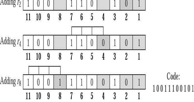
63 Synchronization Synchronous communication (bit-oriented) Timing is recovered from the signal itself (by the carrier if the signal is analog, or by regular transitions in the data signal or by a separate clock line if the signal is digital). Scrambling is often used to ensure frequent transitions needed. The data transmitted may be of any bit length, but is often constrained by the frame transfer protocol (data link or MAC protocol). Bit-oriented framing only assumes that bit synchronization has been achieved by the underlying hardware, and the incoming bit stream is scanned at all possible bit positions for special patterns generated by the sender. Bharati Vidyapeeth s Institute of Computer Applications and Management, New Delhi-63 by Vishal Jain U2.187 Synchronization The sender uses a special pattern (a flag pattern) to delimit frames (one flag at each end), and has to provide for data transparency by use of bit stuffing (see below). A commonly used flag pattern is HDLC's flag The bit sequence is used for both preamble and postamble for the purpose p of synchronization. Bharati Vidyapeeth s Institute of Computer Applications and Management, New Delhi-63 by Vishal Jain U2.188 Synchronization Bit stuffing: If the flag pattern appears anywhere in the header or data of a frame, then the receiver may prematurely detect the start or end of the received frame. To overcome this problem, the sender makes sure that the frame body it sends has no flags in it at any position (note that since there is no character synchronization, The flag pattern can start at any bit location within the stream). It does this by bit stuffing, inserting an extra bit in any pattern that is beginning to look like a flag. Bharati Vidyapeeth s Institute of Computer Applications and Management, New Delhi-63 by Vishal Jain U2.189 Bharati Vidyapeeth s Institute of Computer Applications and Management, Delhi-63 by Vishal Jain U2. 63
64 Synchronization In HDLC, whenever 5 consecutive 1's are encountered in the data, a 0 is inserted after the 5th 1, regardless of the next bit in the data. On the receiving end, the bit stream is piped through a shift register as the receiver looks for the flag pattern. If 5 consecutive 1's followedbya0isseen,thenthe0isdroppedbeforesendingthe data on (the receiver destuffs the stream). If 61'sanda0areseen, It is a flag and either the current frame are ended or a new frame is started, depending on the current state of the receiver. If more than 6 consecutive 1's are seen, then the receiver has detected an invalid pattern, and usually the current frame, if any, is discarded. Bharati Vidyapeeth s Institute of Computer Applications and Management, New Delhi-63 by Vishal Jain U2.190 Synchronization Bharati Vidyapeeth s Institute of Computer Applications and Management, New Delhi-63 by Vishal Jain U2.191 Synchronization Asynchronous communication (word-oriented) In asynchronous communication, small, fixed-length words (usually 5 to 9 bits long) are transferred without any clock line or clock is recovered from the signal itself. Each word has a start bit (usually as a 0) before the first data bit of the word and astopbit (usually asa1) after the last data bit of the word. The receiver's local clock is started when the receiver detects the 1-0 transition of the start bit, and the line is sampled in the middle of the fixed bit intervals (a bit interval is the inverse of the data rate). Bharati Vidyapeeth s Institute of Computer Applications and Management, New Delhi-63 by Vishal Jain U2.192 Bharati Vidyapeeth s Institute of Computer Applications and Management, Delhi-63 by Vishal Jain U2. 64
65 Synchronization The sender outputs the bit at the agreed-upon rate, holding the line in the appropriate state for one bit interval for each bit, but using its own local clock to determine the length of these bit intervals. The receiver's clock and the sender's clock may not run at the same speed, so that there is a relative clock drift (this may be caused by variations i in the crystals used, temperature, voltage, etc.). If the receiver's clock drifts too much relative to the sender's clock, then the bits may be sampled while the line is in transition from one state to another, causing the receiver to misinterpret the received data. There can be variable amount of gap between two frames Bharati Vidyapeeth s Institute of Computer Applications and Management, New Delhi-63 by Vishal Jain U2.193 Synchronization Bharati Vidyapeeth s Institute of Computer Applications and Management, New Delhi-63 by Vishal Jain U2.194 Synchronization Most commonly, a DLE (data link escape) character is used to signal that the next character is a control character, with DLE SOH (start of header) used to indicate the start of the frame (it starts with a header), DLE STX (start of text) used to indicate the end of the header and start of the data portion, and DLE ETX (end of text) used to indicate the end of the frame. A serious problem occurs with this method when binary data, such as object program are being transmitted. It may easily happen when the characters for DLE STX or DLE ETX occur in the data, which will interfere with the framing. One way to overcome this problem is to use character stuffing discussed below. Bharati Vidyapeeth s Institute of Computer Applications and Management, New Delhi-63 by Vishal Jain U2.195 Bharati Vidyapeeth s Institute of Computer Applications and Management, Delhi-63 by Vishal Jain U2. 65
66 Synchronization Bharati Vidyapeeth s Institute of Computer Applications and Management, New Delhi-63 by Vishal Jain U2.196 DTE-DCE interface Bharati Vidyapeeth s Institute of Computer Applications and Management, New Delhi-63 by Vishal Jain U2.197 Topic Local Area Nt Networks: Ethernet Bharati Vidyapeeth s Institute of Computer Applications and Management, New Delhi-63 by Vishal Jain U2.198 Bharati Vidyapeeth s Institute of Computer Applications and Management, Delhi-63 by Vishal Jain U2. 66


67 Learning Objectives To introduce the three generation of ethernet To describe the different stages in these three generations Traditional Ethernet Fast Ethernet Gigabit Ethernet Bharati Vidyapeeth s Institute of Computer Applications and Management, New Delhi-63 by Vishal Jain U2.199 Three generations of Ethernet Bharati Vidyapeeth s Institute of Computer Applications and Management, New Delhi-63 by Vishal Jain U2.200 Traditional Ethernet MAC Sublayer Physical Layer Physical Layer Implementation Bridged Ethernet Switched Ethernet Full-Duplex Ethernet Bharati Vidyapeeth s Institute of Computer Applications and Management, New Delhi-63 by Vishal Jain U2.201 Bharati Vidyapeeth s Institute of Computer Applications and Management, Delhi-63 by Vishal Jain U2. 67


68 MAC frame Bharati Vidyapeeth s Institute of Computer Applications and Management, New Delhi-63 by Vishal Jain U2.202 Minimum and maximum length Bharati Vidyapeeth s Institute of Computer Applications and Management, New Delhi-63 by Vishal Jain U2.203 Ethernet addresses in hexadecimal notation Bharati Vidyapeeth s Institute of Computer Applications and Management, New Delhi-63 by Vishal Jain U2.204 Bharati Vidyapeeth s Institute of Computer Applications and Management, Delhi-63 by Vishal Jain U2. 68


69 Unicast and multicast addresses Bharati Vidyapeeth s Institute of Computer Applications and Management, New Delhi-63 by Vishal Jain U2.205 Physical layer Bharati Vidyapeeth s Institute of Computer Applications and Management, New Delhi-63 by Vishal Jain U2.206 PLS Bharati Vidyapeeth s Institute of Computer Applications and Management, New Delhi-63 by Vishal Jain U2.207 Bharati Vidyapeeth s Institute of Computer Applications and Management, Delhi-63 by Vishal Jain U2. 69
 Bharati Vidyapeeth s Institute of Computer Applications and Management, New Delhi-63 by Vishal")

70 AUI Bharati Vidyapeeth s Institute of Computer Applications and Management, New Delhi-63 by Vishal Jain U2.208 MAU (transceiver) Bharati Vidyapeeth s Institute of Computer Applications and Management, New Delhi-63 by Vishal Jain U2.209 Categories of traditional Ethernet Bharati Vidyapeeth s Institute of Computer Applications and Management, New Delhi-63 by Vishal Jain U2.210 Bharati Vidyapeeth s Institute of Computer Applications and Management, Delhi-63 by Vishal Jain U2. 70

 cable supports Gigabit Ethernet.")
71 Categories of traditional Ethernet Name Segment Length (Max.) Cable 10Base5 10Base2 10Base-T 500m / 1640ft. 185m / 606ft. 100m / 328ft. RG-8 or RG-11 coaxial RG 58 A/U or RG 58 C/U coaxial Category 3 or better unshielded twisted pair Bharati Vidyapeeth s Institute of Computer Applications and Management, New Delhi-63 by Vishal Jain U2.211 Categories of traditional Ethernet Ethernet cables likewise are manufactured to any of several standard specifications. The most popular Ethernet cable in current use, Category 5 or CAT5, supports both traditional and Fast Ethernet. The Category 5e (CAT5e) cable supports Gigabit Ethernet. To connect Ethernet cables to a computer, a person normally uses a network adapter, also known as a network interface card (NIC). Ethernet adapters interfaces directly with a computer's system bus. The cables, in turn, utilize connectors that in many cases look like the RJ-45 connector used with modern telephones. Bharati Vidyapeeth s Institute of Computer Applications and Management, New Delhi-63 by Vishal Jain U2.212 Connection of a station to the medium using 10Base5 Bharati Vidyapeeth s Institute of Computer Applications and Management, New Delhi-63 by Vishal Jain U2.213 Bharati Vidyapeeth s Institute of Computer Applications and Management, Delhi-63 by Vishal Jain U2. 71
 b) avoiding the need to completely re-cable existing Ethernet networks.")
72 Connection of a station to the medium using 10Base5 Fast Ethernet In the mid-1990s, Fast Ethernet technology matured and met its design goals of a) increasing the performance of traditional Ethernet while b) b) avoiding the need to completely re-cable existing Ethernet networks. Fast Ethernet comes in two major varieties: 100Base-T (using unshielded twisted pair cable) 100Base-FX (using fiber optic cable) Bharati Vidyapeeth s Institute of Computer Applications and Management, New Delhi-63 by Vishal Jain U2.214 Connection of stations to the medium using 10Base2 Bharati Vidyapeeth s Institute of Computer Applications and Management, New Delhi-63 by Vishal Jain U2.215 Connection of stations to the medium using 10Base-T Bharati Vidyapeeth s Institute of Computer Applications and Management, New Delhi-63 by Vishal Jain U2.216 Bharati Vidyapeeth s Institute of Computer Applications and Management, Delhi-63 by Vishal Jain U2. 72
.")

73 Connection of stations to the medium using 10Base-FL Whereas Fast Ethernet improved traditional Ethernet from 10 Megabit to 100 Megabit speed, Gigabit Ethernet boasts the same order-of-magnitude improvement over Fast Ethernet by offering speeds of 1000 Megabits (1 Gigabit). Gigabit Ethernet was first made to travel over optical and copper cabling, but the 1000Base-T standard successfully supports it as well. 1000Base-T uses Category 5 cabling similar to 100 Mbps Ethernet, although achieving gigabit speed requires the use of additional wire pairs. Bharati Vidyapeeth s Institute of Computer Applications and Management, New Delhi-63 by Vishal Jain U2.217 Connection of stations to the medium using 10Base-FL Bharati Vidyapeeth s Institute of Computer Applications and Management, New Delhi-63 by Vishal Jain U2.218 Collision domains in a nonbridged and bridged network Bharati Vidyapeeth s Institute of Computer Applications and Management, New Delhi-63 by Vishal Jain U2.219 Bharati Vidyapeeth s Institute of Computer Applications and Management, Delhi-63 by Vishal Jain U2. 73


74 Switched Ethernet Switched Ethernet An Ethernet switch is a bridge which can connect more than two segments together. The idea behind a switch is that it removes all unneeded traffic from each segment by only forwarding the traffic needed on that segment, which provides better performance on the network. Bharati Vidyapeeth s Institute of Computer Applications and Management, New Delhi-63 by Vishal Jain U2.220 Switched Ethernet Bharati Vidyapeeth s Institute of Computer Applications and Management, New Delhi-63 by Vishal Jain U2.221 Full-duplex switched Ethernet Bharati Vidyapeeth s Institute of Computer Applications and Management, New Delhi-63 by Vishal Jain U2.222 Bharati Vidyapeeth s Institute of Computer Applications and Management, Delhi-63 by Vishal Jain U2. 74


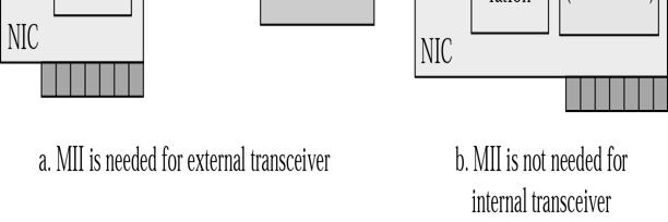
75 Fast Ethernet MAC Sublayer Physical Layer Physical Layer Implementation Bharati Vidyapeeth s Institute of Computer Applications and Management, New Delhi-63 by Vishal Jain U2.223 Fast Ethernet Physical Layer Bharati Vidyapeeth s Institute of Computer Applications and Management, New Delhi-63 by Vishal Jain U2.224 MII Bharati Vidyapeeth s Institute of Computer Applications and Management, New Delhi-63 by Vishal Jain U2.225 Bharati Vidyapeeth s Institute of Computer Applications and Management, Delhi-63 by Vishal Jain U2. 75


76 Fast Ethernet Implementations Bharati Vidyapeeth s Institute of Computer Applications and Management, New Delhi-63 by Vishal Jain U Base-TX Implementation Bharati Vidyapeeth s Institute of Computer Applications and Management, New Delhi-63 by Vishal Jain U2.227 Encoding and decoding in 100Base-TX Bharati Vidyapeeth s Institute of Computer Applications and Management, New Delhi-63 by Vishal Jain U2.228 Bharati Vidyapeeth s Institute of Computer Applications and Management, Delhi-63 by Vishal Jain U2. 76


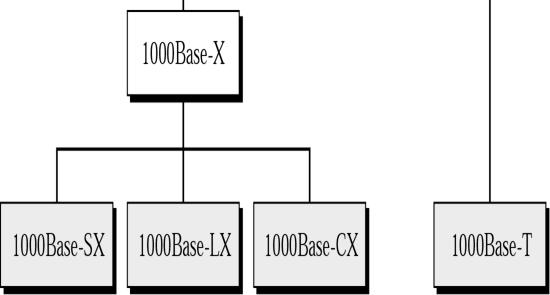
77 Gigabit Ethernet MAC Sublayer Physical Layer Physical Layer Implementation Bharati Vidyapeeth s Institute of Computer Applications and Management, New Delhi-63 by Vishal Jain U2.229 Physical Layer in Gigabit Ethernet Bharati Vidyapeeth s Institute of Computer Applications and Management, New Delhi-63 by Vishal Jain U2.230 Gigabit Ethernet Implementations Bharati Vidyapeeth s Institute of Computer Applications and Management, New Delhi-63 by Vishal Jain U2.231 Bharati Vidyapeeth s Institute of Computer Applications and Management, Delhi-63 by Vishal Jain U2. 77


78 1000Base-X Implementation Bharati Vidyapeeth s Institute of Computer Applications and Management, New Delhi-63 by Vishal Jain U2.232 Encoding in 1000Base-X Bharati Vidyapeeth s Institute of Computer Applications and Management, New Delhi-63 by Vishal Jain U Base-T Implementation Bharati Vidyapeeth s Institute of Computer Applications and Management, New Delhi-63 by Vishal Jain U2.234 Bharati Vidyapeeth s Institute of Computer Applications and Management, Delhi-63 by Vishal Jain U2. 78
79 Conclusion Medium Access control can be random acess, controlled or channelised. In CSMA station must listen to the medium first CSMA/CD is CSMA with post collision procedure CSMA/CA is CSMA with procedure that avoids collision Bharati Vidyapeeth s Institute of Computer Applications and Management, New Delhi-63 by Vishal Jain U2.235 Topic Wireless LANs Bharati Vidyapeeth s Institute of Computer Applications and Management, New Delhi-63 by Vishal Jain U2.236 IEEE Architecture Physical Layer MAC Layer Addressing Mechanism Bharati Vidyapeeth s Institute of Computer Applications and Management, New Delhi-63 by Vishal Jain U2.237 Bharati Vidyapeeth s Institute of Computer Applications and Management, Delhi-63 by Vishal Jain U2. 79
80 Wireless LANs Some of the advantages are mentioned below : Availability of low-cost portable equipments: Due to the technology enhancements, the equipment cost that are required for WLAN set-up have reduced a lot. Mobility: An increasing number of LAN users are becoming mobile. These mobile users require that they are connected to the network regardless of where they are because they want simultaneous access to the network. This makes the use of cables, or wired LANs, impractical if not impossible. Wireless LAN can provide users mobility, which is likely to increase productivity, user convenience and various service opportunities Bharati Vidyapeeth s Institute of Computer Applications and Management, New Delhi-63 by Vishal Jain U2.238 Wireless LANs Installation speed and simplicity: Wireless LANs are very easy to install. There is no requirement for wiring every workstation and every room. This ease of installation makes wireless LANs inherently flexible. Installation flexibility: If a company moves to a new location, the wireless system is much easier to move than ripping up all of the cables that a wired system would have snaked throughout the building. This also provides portability. Wireless technology allows network to go anywhere wire cannot reach. Bharati Vidyapeeth s Institute of Computer Applications and Management, New Delhi-63 by Vishal Jain U2.239 Wireless LANs Reduced cost of ownership: While the initial cost of wireless LAN can be higher than the cost of wired LAN hardware, it is envisaged that the overall installation expenses and life cycle costs can be significantly lower. Long-term cost-benefits are greater in dynamic environment requiring frequent moves and changes. Scalability: Wireless LAN can be configured in a variety of topologies to meet the users need and can be easily scaled to cover a large area with thousands of users roaming within it. Bharati Vidyapeeth s Institute of Computer Applications and Management, New Delhi-63 by Vishal Jain U2.240 Bharati Vidyapeeth s Institute of Computer Applications and Management, Delhi-63 by Vishal Jain U2. 80
81 IEEE Architecture IEEE has defined the specifications for a Wireless LAN, called IEEE , which covers the physical and data link layers. The standard defines two kinds of services : BSS (Basic Service Set) ESS (Extended Service Set) Bharati Vidyapeeth s Institute of Computer Applications and Management, New Delhi-63 by Vishal Jain U2.241 IEEE Architecture BSS IEEE defines the BSS as the building block of a wireless LAN. A basic service set is made of stationary or mobile wireless stations and an optional central base station, known as the access point (AP). BSS without an AP is stand alone network and can not send data to other BSSs. It is called an ad-hoc network architecture. Bharati Vidyapeeth s Institute of Computer Applications and Management, New Delhi-63 by Vishal Jain U2.242 IEEE Architecture In this architecture, stations can form a network without the need of an AP. They can locate one another and agree to be part of a BSS. A BSS with an AP is sometimes referred to as an infrastructure network. Bharati Vidyapeeth s Institute of Computer Applications and Management, New Delhi-63 by Vishal Jain U2.243 Bharati Vidyapeeth s Institute of Computer Applications and Management, Delhi-63 by Vishal Jain U2. 81
82 BSSs Bharati Vidyapeeth s Institute of Computer Applications and Management, New Delhi-63 by Vishal Jain U2.244 IEEE Architecture ESS An ESS is made up of two or more BSSs with APs. In this case, the BSSs are connected through a distribution system, which is usually a wired LAN. The distribution system connects the APs in the BSSs. IEEE des not restrict the distribution system; it can be any IEEE LAN such as Ethernet. Bharati Vidyapeeth s Institute of Computer Applications and Management, New Delhi-63 by Vishal Jain U2.245 IEEE Architecture The extended service set uses two types of stations : Mobile :- Mobile stations are normal stations inside a BSS. Stationary :- Stationary stations are AP stations that are part of a wired LAN. Bharati Vidyapeeth s Institute of Computer Applications and Management, New Delhi-63 by Vishal Jain U2.246 Bharati Vidyapeeth s Institute of Computer Applications and Management, Delhi-63 by Vishal Jain U2. 82


83 ESS Bharati Vidyapeeth s Institute of Computer Applications and Management, New Delhi-63 by Vishal Jain U2.247 ESS When BSSs are connected, the stations within reach of one another can communicate without the use of an AP. However, communication between two stations in two different BSSs usually occurs via two APs. The idea is similar to communication in a cellular network if we consider each BSS to be cell. Each AP to be a base station. Note that a mobile station can belong to more than one BSS at the same time. Bharati Vidyapeeth s Institute of Computer Applications and Management, New Delhi-63 by Vishal Jain U2.248 Station Types IEEE , defines three types ios atations based on their mobility in a wireless Lan No-transition A station with no-transition mobility is either stationary or moving only inside a BSS BSS-transition A station with BSS-transition mobility can move from one BSS to another, but the movement is confined inside one ESS. ESS-transition A station with ESS-transition mobility can move from one ESS to another. Bharati Vidyapeeth s Institute of Computer Applications and Management, New Delhi-63 by Vishal Jain U2.249 Bharati Vidyapeeth s Institute of Computer Applications and Management, Delhi-63 by Vishal Jain U2. 83


84 Physical Layer Specifications Multiplexing l i Techniques Bharati Vidyapeeth s Institute of Computer Applications and Management, New Delhi-63 by Vishal Jain U2.250 Physical Layer Specifications Bharati Vidyapeeth s Institute of Computer Applications and Management, New Delhi-63 by Vishal Jain U2.251 FHSS The idea behind spread spectrum is to spread the signal over a wider frequency band, so as to make jamming and interception more difficult and to minimize the effect of interference from other devices In FH it is done by transmitting the signal over a random sequence of frequencies; that is, first transmitting at one frequency, then second, then a third and so on. The random sequence of frequencies is generated with the help of a pseudorandom number generator. As both the receiver and sender use the same algorithm to generate random sequence, both the devices hop frequencies in a synchronous manner and frames transmitted by the sender are received correctly by the receiver. Bharati Vidyapeeth s Institute of Computer Applications and Management, New Delhi-63 by Vishal Jain U2.252 Bharati Vidyapeeth s Institute of Computer Applications and Management, Delhi-63 by Vishal Jain U2. 84
85 FHSS This is somewhat similar to sending different parts of one song over several FM channels. Eavesdroppers hear only unintelligible blips and any attempt to jam the signal results in damaging a few bits only. Bharati Vidyapeeth s Institute of Computer Applications and Management, New Delhi-63 by Vishal Jain U2.253 DSSS With direct sequence spread spectrum the transmission signal is spread over an allowed band (for example 25MHz). A random binary string is used to modulate the transmitted signal. This random string is called the spreading code. The data bits are mapped to into a pattern of "chips" and mapped back into a bit at the destination. The number of chips that represent a bit is the spreading ratio. Bharati Vidyapeeth s Institute of Computer Applications and Management, New Delhi-63 by Vishal Jain U2.254 DSSS The higher the spreading ratio, the more the signal is resistant to interference. The lower the spreading ratio, the more bandwidth is available to the user. The FCC dictates that the spreading ratio must be more than ten. Most products have a spreading ratio of less than 20 and the new IEEE standard requires a spreading ratio of eleven. The transmitter and the receiver must be synchronized with the same spreading code. Bharati Vidyapeeth s Institute of Computer Applications and Management, New Delhi-63 by Vishal Jain U2.255 Bharati Vidyapeeth s Institute of Computer Applications and Management, Delhi-63 by Vishal Jain U2. 85

86 DSSS If orthogonal spreading codes are used then more than one LAN can share the same band. However, because DSSS systems use wide sub channels, the number of co-located LANs is limited by the size of those sub channels. Recovery is faster in DSSS systems because of the ability to spread the signal over a wider band. Bharati Vidyapeeth s Institute of Computer Applications and Management, New Delhi-63 by Vishal Jain U2.256 FHSS Bharati Vidyapeeth s Institute of Computer Applications and Management, New Delhi-63 by Vishal Jain U2.257 DSSS Bharati Vidyapeeth s Institute of Computer Applications and Management, New Delhi-63 by Vishal Jain U2.258 Bharati Vidyapeeth s Institute of Computer Applications and Management, Delhi-63 by Vishal Jain U2. 86
87 MAC layers in IEEE standard Bharati Vidyapeeth s Institute of Computer Applications and Management, New Delhi-63 by Vishal Jain U2.259 MAC layers in IEEE standard IEEE defines two MAC sublayers DCF (Distributed Coordination Function) PCF (Point Coordination Function) Bharati Vidyapeeth s Institute of Computer Applications and Management, New Delhi-63 by Vishal Jain U2.260 MAC layers in IEEE standard DCF (Distributed Coordination Function) DCF uses CSMA/CA as the access method. Wireless LANs can not implement CSMA/CD due to following reasons : Costly stations and increased bandwidth requirements. Hidden station ti problem Signal fading if distance is great Bharati Vidyapeeth s Institute of Computer Applications and Management, New Delhi-63 by Vishal Jain U2.261 Bharati Vidyapeeth s Institute of Computer Applications and Management, Delhi-63 by Vishal Jain U2. 87

; then the station sends a control frame called the request to send (RTS).")
88 CSMA/CA flowchart Bharati Vidyapeeth s Institute of Computer Applications and Management, New Delhi-63 by Vishal Jain U2.262 CSMA/CA and NAV Bharati Vidyapeeth s Institute of Computer Applications and Management, New Delhi-63 by Vishal Jain U2.263 CSMA/CA Process 1. Before sending a frame, the source station senses the medium by checking the energy level at the carrier frequency. a. The channel use a persistence strategy with back-off until the channel is idle. b. After the station is found to be idle, the station waits for a period of time called distribution interframe space (DIFS); then the station sends a control frame called the request to send (RTS). Bharati Vidyapeeth s Institute of Computer Applications and Management, New Delhi-63 by Vishal Jain U2.264 Bharati Vidyapeeth s Institute of Computer Applications and Management, Delhi-63 by Vishal Jain U2. 88
89 CSMA/CA Process 2. After receiving the RTS and waiting a period of time called the short interframe space (SIFS), the destination sends a control frame, called the clear to send (CTS), to the source station. This control frame indicates that the destination station is ready to receive data. 3. The source station sends data after waiting an amount of time equal to SIFS. 4. The destination station, after waiting an amount of time equal to SIFS, sends an ACK to show that the frame has been received. 5. ACK is needed in this protocol because the station does not have any means to check for the successful arrival of its data at the destination. Bharati Vidyapeeth s Institute of Computer Applications and Management, New Delhi-63 by Vishal Jain U2.265 CSMA/CA process On the other hand, the lack of collision in CSMA/CD is a kind of indication to the source that data have arrived. Bharati Vidyapeeth s Institute of Computer Applications and Management, New Delhi-63 by Vishal Jain U2.266 NAV When a station send a RTS frame, it includes the duration of time that it needs to occupy the channel. The stations that are affected by this transmission create a time called a network allocation vector (NAV) that shows how much time must pass before these stations are allowed to check the channel for idleness. Each time a station accesses the system and sends an RTS frame, other stations start their NAV. In other words, each station, before sensing the physical medium to see if it is idle, first checks its NAV to see if it has expired. Bharati Vidyapeeth s Institute of Computer Applications and Management, New Delhi-63 by Vishal Jain U2.267 Bharati Vidyapeeth s Institute of Computer Applications and Management, Delhi-63 by Vishal Jain U2. 89
90 PCF Point Coordination Function It is an optional access method that can be implemented in an infrastructure network (not in an ad-hoc network). It is implemented on top of the DCF and is used mostly for timesensitive transmission. PCF has centralized, contention free polling access method. The AP performs polling for stations that are being polled. The stations are polled one after another, sending any data they have to the AP. Bharati Vidyapeeth s Institute of Computer Applications and Management, New Delhi-63 by Vishal Jain U2.268 PCF To give priority to PCF over DCF, another set of interframe spaces has been defined : PIFS and SIFS. SIFS is as same as DCF PIFS (PCF IFS) is shorter than the DIFS. This means that if, at the same time, a station wants to use only DCF and an AP wants to use PCF, the AP has priority. Bharati Vidyapeeth s Institute of Computer Applications and Management, New Delhi-63 by Vishal Jain U2.269 Frame Format Bharati Vidyapeeth s Institute of Computer Applications and Management, New Delhi-63 by Vishal Jain U2.270 Bharati Vidyapeeth s Institute of Computer Applications and Management, Delhi-63 by Vishal Jain U2. 90
 except one, this field defines the duration of the transmission. That is used to set the value of NAV.")
91 Frame format FC Frame Control The FC field is used to define the type of frame and some control information. D in all frames (data frames, control frames, management frames ) except one, this field defines the duration of the transmission. That is used to set the value of NAV. In control frame, this field defines the ID of the frame. Addresses To DS and dfrom DS Sequence control - defines sequence number of the frame to be used in flow control. Frame body data FCS - CRC Bharati Vidyapeeth s Institute of Computer Applications and Management, New Delhi-63 by Vishal Jain U2.271 Subfields in FC field Field Explanation Version The current version is 0. Type Type of information: management (00), control (01), or data (10). Subtype Defines the subtype of each type (see ). To DS From DS More flag Retry Pwr mgt More data Defined later. Defined later. When set to 1, means more fragments. When set to 1, means retransmitted frame. When set to 1, means station is in power management mode. When set to 1, means station has more data to send. WEP Rsvd Wired equivalent privacy. When set to 1, means encryption implemented. Reserved. Bharati Vidyapeeth s Institute of Computer Applications and Management, New Delhi-63 by Vishal Jain U2.272 Control Frames Control frames are used for accessing the channel and acknowledging frames. Bharati Vidyapeeth s Institute of Computer Applications and Management, New Delhi-63 by Vishal Jain U2.273 Bharati Vidyapeeth s Institute of Computer Applications and Management, Delhi-63 by Vishal Jain U2. 91
92 Cont. Table Values of subfields in control frames Subtype Meaning 1011 Request to send (RTS) 1100 Clear to send (CTS) 1101 Acknowledgment (ACK) Bharati Vidyapeeth s Institute of Computer Applications and Management, New Delhi-63 by Vishal Jain U2.274 Cont. Table Subfields in FC field To DS From DS Address 1 Address 2 Address 3 Address Destination station Destination station tti Receiving AP Receiving AP Source station Sending AP Source station Sending AP BSS ID Source station tti Destination station Destination station N/A N/A N/A Source station Bharati Vidyapeeth s Institute of Computer Applications and Management, New Delhi-63 by Vishal Jain U2.275 Addressing Mechanism: Case 1 Bharati Vidyapeeth s Institute of Computer Applications and Management, New Delhi-63 by Vishal Jain U2.276 Bharati Vidyapeeth s Institute of Computer Applications and Management, Delhi-63 by Vishal Jain U2. 92
93 Addressing Mechanism: Case 2 Bharati Vidyapeeth s Institute of Computer Applications and Management, New Delhi-63 by Vishal Jain U2.277 Addressing Mechanism: Case 4 Bharati Vidyapeeth s Institute of Computer Applications and Management, New Delhi-63 by Vishal Jain U2.278 Bluetooth Architecture Radio Layer Baseband Layer L2CAP Layer Other Upper Layers Bharati Vidyapeeth s Institute of Computer Applications and Management, New Delhi-63 by Vishal Jain U2.279 Bharati Vidyapeeth s Institute of Computer Applications and Management, Delhi-63 by Vishal Jain U2. 93
94 Bluetooth Bluetooth wireless technology is a short-range radio technology, which is developed for Personal Area Network (PAN). Bluetooth is a standard developed by a group of electronics manufacturers that allows any sort of electronic equipment -- from computers and cell phones to keyboards and headphones -- to make its own connections, without wires, cables or any direct action from a user. It is an ad hoc type network operable over a small area such as a room. Bharati Vidyapeeth s Institute of Computer Applications and Management, New Delhi-63 by Vishal Jain U2.280 Bluetooth Bluetooth wireless technology makes it possible to transmit signals over short distances between telephones, computers and other devices and there by simplify communication and synchronization between devices.. It is a global standard that: Eliminates wires and cables between both stationary and mobile devices Facilitates both data and voice communication Offers the possibility of ad hoc networks and delivers the ultimate synchronicity between all your personal devices Bharati Vidyapeeth s Institute of Computer Applications and Management, New Delhi-63 by Vishal Jain U2.281 Bluetooth Bluetooth is a dynamic standard where devices can automatically find each other, establish connections, and discover what they can do for each other on an ad hoc basis. Bluetooth is intended to be a standard that works at two levels: l It provides agreement at the physical level -- Bluetooth is a radio-frequency standard. It also provides agreement at the next level up, where products have to agree on when bits are sent, how many will be sent at a time and how the parties in a conversation can be sure that the message received is the same as the message sent. Bharati Vidyapeeth s Institute of Computer Applications and Management, New Delhi-63 by Vishal Jain U2.282 Bharati Vidyapeeth s Institute of Computer Applications and Management, Delhi-63 by Vishal Jain U2. 94
95 Bluetooth There are two types of topology for Bluetooth Piconet, Scatternet. The Piconet is a small ad hoc network of devices (normally 8 stations) as shown in Fig. It has the following features: One is called Master and the others are called Slaves All slave stations synchronizes their clocks with the master Possible communication - One-to-one or one-to-many There may be one station in parked state Each piconet has a unique hopping pattern/id Each master can connect to 7 simultaneous or 200+ inactive (parked) slaves per piconet Bharati Vidyapeeth s Institute of Computer Applications and Management, New Delhi-63 by Vishal Jain U2.283 Piconet Bharati Vidyapeeth s Institute of Computer Applications and Management, New Delhi-63 by Vishal Jain U2.284 Scatternet By making one slave as master of another Piconet, Scatternet is formed by combining several Piconets as shown in Fig. Key features of the scatternet topology are mentioned below: A Scatternet is the linking of multiple co-located piconets through the sharing of common master or slave devices. A device can be both a master and a slave. Radios are symmetric (same radio can be master or slave). High capacity system, each piconet has maximum capacity (720 Kbps) Bharati Vidyapeeth s Institute of Computer Applications and Management, New Delhi-63 by Vishal Jain U2.285 Bharati Vidyapeeth s Institute of Computer Applications and Management, Delhi-63 by Vishal Jain U2. 95

96 Scatternet Bharati Vidyapeeth s Institute of Computer Applications and Management, New Delhi-63 by Vishal Jain U2.286 Bluetooth Layers Bharati Vidyapeeth s Institute of Computer Applications and Management, New Delhi-63 by Vishal Jain U2.287 Bluetooth Layers The Bluetooth architecture, showing all the major layers in the Bluetooth system, are depicted in the Fig. The layers below can be considered to be different hurdles in an obstacle course. This is because all the layers function one after the other. One layer comes into play only after the data has been through the previous layer. Bharati Vidyapeeth s Institute of Computer Applications and Management, New Delhi-63 by Vishal Jain U2.288 Bharati Vidyapeeth s Institute of Computer Applications and Management, Delhi-63 by Vishal Jain U2. 96
Chapter 3. The Data Link Layer. Wesam A. Hatamleh
 Chapter 3 The Data Link Layer The Data Link Layer Data Link Layer Design Issues Error Detection and Correction Elementary Data Link Protocols Sliding Window Protocols Example Data Link Protocols The Data
Data Link Control. Claude Rigault ENST Claude Rigault, ENST 11/3/2002. Data Link control 1
 Data Link Control Claude Rigault ENST claude.rigault@enst.fr Data Link control Data Link Control Outline General principles of Data Link Control HDLC Data Link control 2 General principles of Data Link
(Sicherungsschicht) Chapter 5 (part 2) [Wa0001] HDLC - 1.
![(Sicherungsschicht) Chapter 5 (part 2) [Wa0001] HDLC - 1.](/thumbs/74/71111055.jpg "(Sicherungsschicht) Chapter 5 (part 2) [Wa0001] HDLC - 1.") Data Link Layer (cont.) (Sicherungsschicht) Chapter 5 (part 2) [Wa0001] HDLC - 1 LOGICAL LINK CONTROL MEDIUM ACCESS CONTROL PHYSICAL SIGNALING DATA LINK LAYER PHYSICAL LAYER ACCESS UNIT INTERFACE PHYSICAL
Data Link Layer (cont.) (Sicherungsschicht) Chapter 5 (part 2) [Wa0001] HDLC - 1 LOGICAL LINK CONTROL MEDIUM ACCESS CONTROL PHYSICAL SIGNALING DATA LINK LAYER PHYSICAL LAYER ACCESS UNIT INTERFACE PHYSICAL
Data Link Layer (cont.) ( h h h ) (Sicherungsschicht) HDLC - 1.
 ( h h h ) (Sicherungsschicht) HDLC - 1.") Data Link Layer (cont.) ( h h h ) (Sicherungsschicht) HDLC - 1 LOGICAL L LINK CONTROL MEDIUM ACCESS CONTROL PHYSICAL SIGNALING DATA LINK LAYER PHYSICAL LAYER ACCESS UNIT INTERFACE PHYSICAL MEDIA ATTACHMENT
Data Link Layer (cont.) ( h h h ) (Sicherungsschicht) HDLC - 1 LOGICAL L LINK CONTROL MEDIUM ACCESS CONTROL PHYSICAL SIGNALING DATA LINK LAYER PHYSICAL LAYER ACCESS UNIT INTERFACE PHYSICAL MEDIA ATTACHMENT
William Stallings Data and Computer Communications. Chapter 7 Data Link Control
 William Stallings Data and Computer Communications Chapter 7 Data Link Control Flow Control Ensuring the sending entity does not overwhelm the receiving entity Preventing buffer overflow Transmission time
HDLC. King of the Link 2005/03/11. (C) Herbert Haas
 Herbert Haas") HDLC King of the Link (C) Herbert Haas 2005/03/11 What is HDLC? High-Level Data Link Control Early link layer protocol Based on SDLC (Synchronous-DLC, IBM) Access control on half-duplex modem-lines Connectionoriented
HDLC King of the Link (C) Herbert Haas 2005/03/11 What is HDLC? High-Level Data Link Control Early link layer protocol Based on SDLC (Synchronous-DLC, IBM) Access control on half-duplex modem-lines Connectionoriented
Data link layer functions. 2 Computer Networks Data Communications. Framing (1) Framing (2) Parity Checking (1) Error Detection
 Framing (2) Parity Checking (1) Error Detection") 2 Computer Networks Data Communications Part 6 Data Link Control Data link layer functions Framing Needed to synchronise TX and RX Account for all bits sent Error control Detect and correct errors Flow
2 Computer Networks Data Communications Part 6 Data Link Control Data link layer functions Framing Needed to synchronise TX and RX Account for all bits sent Error control Detect and correct errors Flow
Data Link Control Protocols
 Data Link Control Protocols need layer of logic above Physical to manage exchange of data over a link frame synchronization flow control error control addressing control and data link management Flow Control
INTERNET ARCHITECTURE & PROTOCOLS
 INTERNET ARCHITECTURE & PROTOCOLS Set # 02 Delivered By: Engr Tahir Niazi Need for Data Link Layer possibility of transmission errors receiver need to regulate the rate at which data arrive that's why
PART III. Data Link Layer MGH T MGH C I 204
 PART III Data Link Layer Position of the data-link layer Data link layer duties LLC and MAC sublayers IEEE standards for LANs Chapters Chapter 10 Error Detection and Correction Chapter 11 Data Link Control
3. Data Link Layer 3-2
 3. Data Link Layer 3.1 Transmission Errors 3.2 Error Detecting and Error Correcting Codes 3.3 Bit Stuffing 3.4 Acknowledgments and Sequence Numbers 3.5 Flow Control 3.6 Examples: HDLC, PPP 3. Data Link
Flow control: Ensuring the source sending frames does not overflow the receiver
 Layer 2 Technologies Layer 2: final level of encapsulation of data before transmission over a physical link responsible for reliable transfer of frames between hosts, hop by hop, i.e. on a per link basis
SRI RAMAKRISHNA INSTITUTE OF TECHNOLOGY DEPARTMENT OF INFORMATION TECHNOLOGY COMPUTER NETWORKS UNIT - II DATA LINK LAYER
 SRI RAMAKRISHNA INSTITUTE OF TECHNOLOGY DEPARTMENT OF INFORMATION TECHNOLOGY COMPUTER NETWORKS UNIT - II DATA LINK LAYER 1. What are the responsibilities of data link layer? Specific responsibilities of
Chapter 7: Data Link Control. CS420/520 Axel Krings Page 1
 Chapter 7: Data Link Control CS420/520 Axel Krings Page 1 Data Link Control Protocols Need layer of logic above Physical to manage exchange of data over a link frame synchronization flow control error
Chapter 7: Data Link Control. Data Link Control Protocols
 Chapter 7: Data Link Control CS420/520 Axel Krings Page 1 Data Link Control Protocols Need layer of logic above Physical to manage exchange of data over a link frame synchronization flow control error
 ET3110 Networking and Communications UNIT 2: Communication Techniques and Data Link Control Protocol skong@itt-tech.edutech.edu Learning Objectives Identify methods of detecting errors. Use Hamming code
Chapter 5 Data-Link Layer: Wired Networks
 Sungkyunkwan University Chapter 5 Data-Link Layer: Wired Networks Prepared by Syed M. Raza and H. Choo 2018-Fall Computer Networks Copyright 2000-2018 Networking Laboratory Chapter 5 Outline 5.1 Introduction
Data and Computer Communications
 Data and Computer Communications Chapter 7 Data Link Control Protocols Eighth Edition by William Stallings Lecture slides by Lawrie Brown Data Link Control Protocols "Great and enlightened one," said Ten-teh,
Line Protocol Basics. HDLC (High level Data Link Control) Agenda. Additional Issues
 Agenda. Additional Issues") Line Protocol Basics High-level Data Link Control HDLC (High level Data Link Control), EIA-232, HDLC Framing and Procedures line protocol basics already explained serial transmission techniques bit-synchronization
Line Protocol Basics High-level Data Link Control HDLC (High level Data Link Control), EIA-232, HDLC Framing and Procedures line protocol basics already explained serial transmission techniques bit-synchronization
HDLC (High level Data Link Control)
") High-level Data Link Control HDLC (High level Data Link Control) Modem, EIA-232, HDLC Framing and Procedures Agenda Line Management, Modems Introduction HDLC Station Types, Modes of Operation Frame Format,
High-level Data Link Control HDLC (High level Data Link Control) Modem, EIA-232, HDLC Framing and Procedures Agenda Line Management, Modems Introduction HDLC Station Types, Modes of Operation Frame Format,
Advanced Computer Networks. Rab Nawaz Jadoon DCS. Assistant Professor COMSATS University, Lahore Pakistan. Department of Computer Science
 Advanced Computer Networks Rab Nawaz Jadoon Department of Computer Science DCS COMSATS Institute of Information Technology Assistant Professor COMSATS University, Lahore Pakistan Advanced Computer Networks
Data Link Layer. Goals of This Lecture. Engineering Questions. Outline of the Class
 Data Link Layer Kuang Chiu Huang TCM NCKU Goals of This Lecture Through the lecture and in-class discussion, students are enabled to describe role and functions of the link layer, and compare different
2.1 CHANNEL ALLOCATION 2.2 MULTIPLE ACCESS PROTOCOLS Collision Free Protocols 2.3 FDDI 2.4 DATA LINK LAYER DESIGN ISSUES 2.5 FRAMING & STUFFING
 UNIT-2 2.1 CHANNEL ALLOCATION 2.2 MULTIPLE ACCESS PROTOCOLS 2.2.1 Pure ALOHA 2.2.2 Slotted ALOHA 2.2.3 Carrier Sense Multiple Access 2.2.4 CSMA with Collision Detection 2.2.5 Collision Free Protocols 2.2.5.1
I. INTRODUCTION. each station (i.e., computer, telephone, etc.) directly connected to all other stations
 directly connected to all other stations") I. INTRODUCTION (a) Network Topologies (i) point-to-point communication each station (i.e., computer, telephone, etc.) directly connected to all other stations (ii) switched networks (1) circuit switched
I. INTRODUCTION (a) Network Topologies (i) point-to-point communication each station (i.e., computer, telephone, etc.) directly connected to all other stations (ii) switched networks (1) circuit switched
CS 4453 Computer Networks Winter
 CS 4453 Computer Networks Chapter 2 OSI Network Model 2015 Winter OSI model defines 7 layers Figure 1: OSI model Computer Networks R. Wei 2 The seven layers are as follows: Application Presentation Session
Department of Computer and IT Engineering University of Kurdistan. Data Communication Netwotks (Graduate level) Data Link Layer
 Data Link Layer") Department of Computer and IT Engineering University of Kurdistan Data Communication Netwotks (Graduate level) Data Link Layer By: Dr. Alireza Abdollahpouri Data Link Layer 2 Data Link Layer Application
Department of Computer and IT Engineering University of Kurdistan Data Communication Netwotks (Graduate level) Data Link Layer By: Dr. Alireza Abdollahpouri Data Link Layer 2 Data Link Layer Application
Multiple Access. Data Communications and Networking
 Multiple Access In the previous part we discussed data link control, a mechanism which provides a link with reliable communication. In the protocols we described, we assumed that there is an available
Other Data Link Protocols: Computer Networks by Prof Kamal K Mehta Associate Professor Dept of Computer Science & Engineering
 Other Data Link Protocols: Data Link Protocol ategories A protocol in data communications is the set of rules or specifications used to implement partially a layer or one or more layers of the OSI model.
Chapter 3. The Data Link Layer
 Chapter 3 The Data Link Layer 1 Data Link Layer Algorithms for achieving reliable, efficient communication between two adjacent machines. Adjacent means two machines are physically connected by a communication
CS254 Network Technologies. Lecture 2: Network Models & Error Detection and Correction. Dr Nikos Antonopoulos
 CS254 Network Technologies Lecture 2: Network Models & Error Detection and Correction Dr Nikos Antonopoulos Department of Computing University of Surrey Autumn 2006 2.1 Layered Tasks Sender, Receiver,
TYPES OF ERRORS. Data can be corrupted during transmission. Some applications require that errors be detected and corrected.
 Data can be corrupted during transmission. Some applications require that errors be detected and corrected. TYPES OF ERRORS There are two types of errors, 1. Single Bit Error The term single-bit error
DATA LINK LAYER UNIT 7.
 DATA LINK LAYER UNIT 7 1 Data Link Layer Design Issues: 1. Service provided to network layer. 2. Determining how the bits of the physical layer are grouped into frames (FRAMING). 3. Dealing with transmission
CS 455/555 Intro to Networks and Communications. Link Layer
 CS 455/555 Intro to Networks and Communications Link Layer Dr. Michele Weigle Department of Computer Science Old Dominion University mweigle@cs.odu.edu http://www.cs.odu.edu/~mweigle/cs455-s13 1 Link Layer
Data Link Layer: Overview, operations
 Data Link Layer: Overview, operations Chapter 3 1 Outlines 1. Data Link Layer Functions. Data Link Services 3. Framing 4. Error Detection/Correction. Flow Control 6. Medium Access 1 1. Data Link Layer
Data Link Control Protocols
 Protocols : Introduction to Data Communications Sirindhorn International Institute of Technology Thammasat University Prepared by Steven Gordon on 23 May 2012 Y12S1L07, Steve/Courses/2012/s1/its323/lectures/datalink.tex,
Links. CS125 - mylinks 1 1/22/14
 Links 1 Goals of Today s Lecture Link-layer services Encoding, framing, and error detection Error correction and flow control Sharing a shared media Channel partitioning Taking turns Random access Shared
OSI Reference Model. Application Layer. Presentation Layer. Session Layer. Chapter 4: Application Protocols. Transport Layer.
 Chapter 2: Computer Networks 2.1: Physical Layer: representation of digital signals 2.2: Data Link Layer: error protection and access control 2.3: Network infrastructure 2.4 2.5: Local Area Network examples
Chapter 11 Data Link Control 11.1
 Chapter 11 Data Link Control 11.1 Copyright The McGraw-Hill Companies, Inc. Permission required for reproduction or display. 11-1 FRAMING The data link layer needs to pack bits into frames, so that each
The data link layer has a number of specific functions it can carry out. These functions include. Figure 2-1. Relationship between packets and frames.
 Module 2 Data Link Layer: - Data link Layer design issues - Error Detection and correction Elementary Data link protocols, Sliding window protocols- Basic Concept, One Bit Sliding window protocol, Concept
Data Link Protocols DATA LINK PROTOCOLS. Asynchronous Protocols. Types of Data Link Protocols XMODEM. Asynchronous Protocols.
 Data Link Protocols DATA LINK PROTOCOLS Data Link Protocols are sets of rule and regulations used to implement data link layer. They contain rules for: Line Discipline Gursharan Singh Tatla mailme@gursharansingh.in
Local Networks. Lecture 4 6-Apr-2016
 Local Networks Lecture 4 6-Apr-2016 Roadmap of the Course So far Basic telecom concepts General study of LANs LAN topologies Flow and error control Today we continue the general study of LANs Medium access
Institute of Computer Technology - Vienna University of Technology. L02 - Protocol Principles
 Protocol Principles Layering, CL versus CO Service, ARQ Techniques, Sequence umbers, Windowing, Flow Control Agenda Introduction 3 Layer Model and Service Types ARQ Techniques Introduction Idle RQ Continuous
Telecom Systems Chae Y. Lee. Contents. Flow Control Error Detection/Correction Link Control (Error Control) Link Performance (Utility)
 Link Performance (Utility)") Data Link Control Contents Flow Control Error Detection/Correction Link Control (Error Control) Link Performance (Utility) 2 Flow Control Flow control is a technique for assuring that a transmitting entity
Data Link Control Contents Flow Control Error Detection/Correction Link Control (Error Control) Link Performance (Utility) 2 Flow Control Flow control is a technique for assuring that a transmitting entity
The Link Layer and LANs. Chapter 6: Link layer and LANs
 The Link Layer and LANs EECS3214 2018-03-14 4-1 Chapter 6: Link layer and LANs our goals: understand principles behind link layer services: error detection, correction sharing a broadcast channel: multiple
Problem Set Name the 7 OSI layers and give the corresponding functionalities for each layer.
 Problem Set 1 1. Why do we use layering in computer networks? 2. Name the 7 OSI layers and give the corresponding functionalities for each layer. 3. Compare the network performance of the 3 Multiple Access
CCNA Exploration1 Chapter 7: OSI Data Link Layer
 CCNA Exploration1 Chapter 7: OSI Data Link Layer LOCAL CISCO ACADEMY ELSYS TU INSTRUCTOR: STELA STEFANOVA 1 Explain the role of Data Link layer protocols in data transmission; Objectives Describe how the
Chapter 5 Link Layer and LANs
 Chapter 5 Link Layer and LANs Computer Networking: A Top Down Approach 4 th edition. Jim Kurose, Keith Ross Addison-Wesley, July 2007. All material copyright 1996-2007 J.F Kurose and K.W. Ross, All Rights
Packet Switching Networks. Dr. Indranil Sen Gupta Packet Switching Networks Slide 1
 Packet Switching Networks Dr. Indranil Sen Gupta Packet Switching Networks Slide 1 Packet Switching (Basic Concepts) New form of architecture for long-distance data communication (1970). Packet switching
Data Link Layer: Collisions
 Data Link Layer: Collisions 1 Multiple Access Data Link layer divided into two sublayers. The upper sublayer is responsible for datalink control, The lower sublayer is responsible for resolving access
Chapter 11 Data Link Control 11.1
 Chapter 11 Data Link Control 11.1 Copyright The McGraw-Hill Companies, Inc. Permission required for reproduction or display. 11-1 1 FRAMING The data link layer needs to pack bits into frames,, so that
HDLC PROTOCOL. Michel GARDIE
 HDLC PROTOCOL Michel GARDIE INT/LOR/RIP October 15, 2007 The version of this document is temporary. There are still several mistakes. I'm sorry for that. email: michel.gardie@int-edu.eu 1985 FRANCE TELECOM
Data Link Technology. Suguru Yamaguchi Nara Institute of Science and Technology Department of Information Science
 Data Link Technology Suguru Yamaguchi Nara Institute of Science and Technology Department of Information Science Agenda Functions of the data link layer Technologies concept and design error control flow
Telecommunication Protocols Laboratory Course. Lecture 2
 Telecommunication Protocols Laboratory Course Lecture 2 Last time We began our study of telecommunication protocols at the Logical Link Control sub-layer (LLC) LLC issues Connectionless vs connection-oriented
Link Layer and LANs 안상현서울시립대학교컴퓨터 통계학과.
 Link Layer and LANs 안상현서울시립대학교컴퓨터 통계학과 ahn@venus.uos.ac.kr Data Link Layer Goals: understand principles behind data link layer services: error detection, correction sharing a broadcast channel: multiple
CEG3185 TUT6. Prepared by Zhenxia Zhang Revisited by Jiying Zhao
 CEG3185 TUT6 Prepared by Zhenxia Zhang Revisited by Jiying Zhao HDLC High Level Data Link Control (HDLC) is a bit oriented synchronous data link layer protocol developed by the International Organization
Links Reading: Chapter 2. Goals of Todayʼs Lecture. Message, Segment, Packet, and Frame
 Links Reading: Chapter 2 CS 375: Computer Networks Thomas Bressoud 1 Goals of Todayʼs Lecture Link-layer services Encoding, framing, and error detection Error correction and flow control Sharing a shared
(Refer Slide Time: 2:20)
") Data Communications Prof. A. Pal Department of Computer Science & Engineering Indian Institute of Technology, Kharagpur Lecture -23 X.25 and Frame Relay Hello and welcome to today s lecture on X.25 and
Data Communications Prof. A. Pal Department of Computer Science & Engineering Indian Institute of Technology, Kharagpur Lecture -23 X.25 and Frame Relay Hello and welcome to today s lecture on X.25 and
COMPUTER NETWORKS UNIT 3
 COMPUTER NETWORKS UNIT 3 1. Illustrate about Reservation, Polling and Token Passing. [10 marks] Controlled access: In controlled access, the stations consult one another to find which station has the right
Outline: Connecting Many Computers
 Outline: Connecting Many Computers Last lecture: sending data between two computers This lecture: link-level network protocols (from last lecture) sending data among many computers 1 Review: A simple point-to-point
CSC 4900 Computer Networks: The Link Layer
 CSC 4900 Computer Networks: The Link Layer Professor Henry Carter Fall 2017 Last Time We talked about intra-as routing protocols: Which routing algorithm is used in RIP? OSPF? What techniques allow OSPF
CHAPTER 7 MAC LAYER PROTOCOLS. Dr. Bhargavi Goswami Associate Professor & Head Department of Computer Science Garden City College
 CHAPTER 7 MAC LAYER PROTOCOLS Dr. Bhargavi Goswami Associate Professor & Head Department of Computer Science Garden City College MEDIUM ACCESS CONTROL - MAC PROTOCOLS When the two stations transmit data
Data & Computer Communication
 Basic Networking Concepts A network is a system of computers and other devices (such as printers and modems) that are connected in such a way that they can exchange data. A bridge is a device that connects
The Data Link Layer Chapter 3
 The Data Link Layer Chapter 3 Data Link Layer Design Issues Error Detection and Correction Elementary Data Link Protocols Sliding Window Protocols Example Data Link Protocols Revised: August 2011 & February
Chapter 12 Multiple Access 12.1
 Chapter 12 Multiple Access 12.1 Copyright The McGraw-Hill Companies, Inc. Permission required for reproduction or display. 12.2 Figure 12.1 Data link layer divided into two functionality-oriented sublayers
Appendix. Pioneering Protocols
 Appendix Pioneering Protocols STUDENTS STUDYING ancient civilizations and languages often wonder what is the point in studying cultures that no longer exist. How will the way people lived hundreds and
Data and Computer Communications. Protocols and Architecture
 Data and Computer Communications Protocols and Architecture Characteristics Direct or indirect Monolithic or structured Symmetric or asymmetric Standard or nonstandard Means of Communication Direct or
INTERNATIONAL TELECOMMUNICATION UNION. SERIES Q: DIGITAL SUBSCRIBER SIGNALLING SYSTEM No. 1 (DSS 1), DATA LINK LAYER
, DATA LINK LAYER") INTERNATIONAL TELECOMMUNICATION UNION CCITT Q.921 THE INTERNATIONAL TELEGRAPH AND TELEPHONE CONSULTATIVE COMMITTEE (11/1988) SERIES Q: DIGITAL SUBSCRIBER SIGNALLING SYSTEM No. 1 (DSS 1), DATA LINK LAYER
INTERNATIONAL TELECOMMUNICATION UNION CCITT Q.921 THE INTERNATIONAL TELEGRAPH AND TELEPHONE CONSULTATIVE COMMITTEE (11/1988) SERIES Q: DIGITAL SUBSCRIBER SIGNALLING SYSTEM No. 1 (DSS 1), DATA LINK LAYER
Lecture 11 Overview. Last Lecture. This Lecture. Next Lecture. Medium Access Control. Flow and error control Source: Sections , 23.
 Last Lecture Lecture 11 Overview Medium Access Control This Lecture Flow and error control Source: Sections 11.1-11.2, 23.2 Next Lecture Local Area Networks 1 Source: Sections 13 Data link layer Logical
ERROR AND FLOW CONTROL. Lecture: 10 Instructor Mazhar Hussain
 ERROR AND FLOW CONTROL Lecture: 10 Instructor Mazhar Hussain 1 FLOW CONTROL Flow control coordinates the amount of data that can be sent before receiving acknowledgement It is one of the most important
This Lecture. BUS Computer Facilities Network Management. Line Discipline. Data Link Layer
 This Lecture US35 - Computer Facilities Network Management Synchronisation and interfacing insufficient by themselves. Need to provide: Flow control - allow the receiver to regulate the flow of data. Error
Multiple Access Protocols
 Multiple Access Protocols Computer Networks Lecture 2 http://goo.gl/pze5o8 Multiple Access to a Shared Channel The medium (or its sub-channel) may be shared by multiple stations (dynamic allocation) just
Chapter 5 Peer-to-Peer Protocols. School of Info. Sci. & Eng. Shandong Univ..
 hapter 5 Peer-to-Peer Protocols School of Info. Sci. & Eng. Shandong Univ.. Outline 5. Peer-to-peer protocols and service models 5. RQ Protocols 5.3 Other daptation Functions Sliding Window Flow ontrol
Introduction to Protocols
 Chapter 6 Introduction to Protocols 1 Chapter 6 Introduction to Protocols What is a Network Protocol? A protocol is a set of rules that governs the communications between computers on a network. These
4. Error correction and link control. Contents
 //2 4. Error correction and link control Contents a. Types of errors b. Error detection and correction c. Flow control d. Error control //2 a. Types of errors Data can be corrupted during transmission.
Transmission SIGNALs
 Chapter 6 Digital Communications Basics 6.1 Introduction 6.2 Transmission media 6.3 Source of signal impairment 6.4 Asynchronous Transmission 6.5 Synchronous Transmission 6.6 Error Detection Methods 6.7
Topics. Link Layer Services (more) Link Layer Services LECTURE 5 MULTIPLE ACCESS AND LOCAL AREA NETWORKS. flow control: error detection:
 Link Layer Services LECTURE 5 MULTIPLE ACCESS AND LOCAL AREA NETWORKS. flow control: error detection:") 1 Topics 2 LECTURE 5 MULTIPLE ACCESS AND LOCAL AREA NETWORKS Multiple access: CSMA/CD, CSMA/CA, token passing, channelization LAN: characteristics, i basic principles i Protocol architecture Topologies
1 Topics 2 LECTURE 5 MULTIPLE ACCESS AND LOCAL AREA NETWORKS Multiple access: CSMA/CD, CSMA/CA, token passing, channelization LAN: characteristics, i basic principles i Protocol architecture Topologies
Data Link Layer. Overview. Links. Shivkumar Kalyanaraman
 Data Link Layer shivkuma@ecse.rpi.edu http://www.ecse.rpi.edu/homepages/shivkuma 1-1 Based in part upon the slides of Prof. Raj Jain (OSU) Overview The data link layer problem Error detection and correction
Part 5: Link Layer Technologies. CSE 3461: Introduction to Computer Networking Reading: Chapter 5, Kurose and Ross
 Part 5: Link Layer Technologies CSE 3461: Introduction to Computer Networking Reading: Chapter 5, Kurose and Ross 1 Outline PPP ATM X.25 Frame Relay 2 Point to Point Data Link Control One sender, one receiver,
The MAC Address Format
 Directing data is what addressing is all about. At the Data Link layer, this is done by pointing PDUs to the destination MAC address for delivery of a frame within a LAN. The MAC address is the number
Lecture 8 The Data Link Layer part I. Antonio Cianfrani DIET Department Networking Group netlab.uniroma1.it
 Lecture 8 The Data Link Layer part I Antonio Cianfrani DIET Department Networking Group netlab.uniroma1.it Link Layer: setting the context two physically connected devices: host-router, router-router,
CS422 Computer Networks
 CS422 Computer Networks Lecture 3 Data Link Layer Dr. Xiaobo Zhou Department of Computer Science CS422 DataLinkLayer.1 Data Link Layer Design Issues Services Provided to the Network Layer Provide service
The University of Sydney AUSTRALIA. Advanced Communication Networks
 The University of Sydney AUSTRALIA School of Electrical and Information Engineering Advanced Communication Networks Chapter 5 ISDN Data Link Layer Based on chapter 8 of Stallings ISDN-4e book Abbas Jamalipour
Chapter 11 in Stallings 10 th Edition
 Local Area Network Overview Chapter 11 in Stallings 10 th Edition CS420/520 Axel Krings Page 1 LAN Applications (1) Personal computer LANs Low cost Limited data rate Back end networks Interconnecting large
Outline. EEC-484/584 Computer Networks. Data Link Layer Design Issues. Framing. Lecture 6. Wenbing Zhao Review.
 EEC-484/584 Computer Networks Lecture 6 wenbing@ieee.org (Lecture nodes are based on materials supplied by Dr. Louise Moser at UCSB and Prentice-Hall) Outline Review Data Link Layer Design Issues Error
Computer Facilities and Network Management BUS3150 Tutorial - Week 13
 Computer Facilities and Network Management BUS3150 Tutorial - Week 13 *** FOR TUTORS ONLY *** The answers provided here are only brief guides. If you have any comments or suggestions for improvement to
Review of Network Technologies
 Indian Institute of Technology Kharagpur Review of Network Technologies Prof. Indranil Sen Gupta Dept. of Computer Science & Engg. I.I.T. Kharagpur, INDIA Lecture 2: Review of network technologies On completion,
INTERNATIONAL TELECOMMUNICATION UNION. SERIES X: DATA COMMUNICATION NETWORKS: SERVICES AND FACILITIES, INTERFACES Interfaces
 INTERNATIONAL TELECOMMUNICATION UNION CCITT X.25 THE INTERNATIONAL TELEGRAPH AND TELEPHONE CONSULTATIVE COMMITTEE (11/1988) SERIES X: DATA COMMUNICATION NETWORKS: SERVICES AND FACILITIES, INTERFACES Interfaces
Analyzation of Automatic Repeat Request (ARQ) Protocols
 Protocols") RESEARCH ARTICLE OPEN ACCESS Analyzation of Automatic Repeat Request (ARQ) Protocols 1 Jeshvina.S, 2 Sneha.P, 3 Saraanya.S Final year BCA, Dept of Computer Science New Horizon College Kasturinagar, Bangalore
RESEARCH ARTICLE OPEN ACCESS Analyzation of Automatic Repeat Request (ARQ) Protocols 1 Jeshvina.S, 2 Sneha.P, 3 Saraanya.S Final year BCA, Dept of Computer Science New Horizon College Kasturinagar, Bangalore
Link layer, LANs: outline. Chapter 5-1 Link Layer. Link layer: introduction. Link layer services
 Chapter 5 Link Layer Computer Networking: A Top Down Approach 6 th edition Jim Kurose, Keith Ross Addison-Wesley March 2012 Link layer, LANs: outline 5.1 introduction, services 5.2 error detection, correction
Automatic Repeat Request Data Link Layer Traffic Management
 Automatic Repeat Request Data Link Layer Traffic Management Reliable Communications with Retransmission How to transport data units over an unreliable data link in a reliable way? End to End E.g.. TCP
The flow of data must not be allowed to overwhelm the receiver
 Data Link Layer: Flow Control and Error Control Lecture8 Flow Control Flow and Error Control Flow control refers to a set of procedures used to restrict the amount of data that the sender can send before
COMPUTER NETWORKS UNIT I. 1. What are the three criteria necessary for an effective and efficient networks?
 Question Bank COMPUTER NETWORKS Short answer type questions. UNIT I 1. What are the three criteria necessary for an effective and efficient networks? The most important criteria are performance, reliability
UNIT IV -- TRANSPORT LAYER
 UNIT IV -- TRANSPORT LAYER TABLE OF CONTENTS 4.1. Transport layer. 02 4.2. Reliable delivery service. 03 4.3. Congestion control. 05 4.4. Connection establishment.. 07 4.5. Flow control 09 4.6. Transmission
Data Link layer (CN chap 3.1, 3.4, 3.6)
") Data Link layer (CN chap 3.1, 3.4, 3.6) The OSI model an old friend... Application Presentation Session Transport Network Data link Physical F.eks. ftp, mail, http,... handles data structures and conversion
Data Link layer (CN chap 3.1, 3.4, 3.6) The OSI model an old friend... Application Presentation Session Transport Network Data link Physical F.eks. ftp, mail, http,... handles data structures and conversion
DATA LINK LAYER: NEED
 Page no: 1 Department of Computer Science and Engineering CS6004 Computer Networking Subject Notes: UNIT-II DATA LINK LAYER: NEED Data Link Layer is second layer of OSI Layered Model. This layer is one
UNIT-II 1. Discuss the issues in the data link layer. Answer:
 UNIT-II 1. Discuss the issues in the data link layer. Answer: Data Link Layer Design Issues: The data link layer has a number of specific functions it can carry out. These functions include 1. Providing
COMPUTER NETWORKS MODEL QUESTION PAPER WITH SOLUTION. (c) Peer-to-peer processes are processes on two or more devices communicating at a
 Peer-to-peer processes are processes on two or more devices communicating at a") COMPUTER NETWORKS MODEL QUESTION PAPER WITH SOLUTION Q-1(a) In half-duplex transmission, only one entity can send at a time; in a full-duplex transmission, both entities can send at the same time. (b)
COMPUTER NETWORKS MODEL QUESTION PAPER WITH SOLUTION Q-1(a) In half-duplex transmission, only one entity can send at a time; in a full-duplex transmission, both entities can send at the same time. (b)
Chapter 2 - Part 1. The TCP/IP Protocol: The Language of the Internet
 Chapter 2 - Part 1 The TCP/IP Protocol: The Language of the Internet Protocols A protocol is a language or set of rules that two or more computers use to communicate 2 Protocol Analogy: Phone Call Parties
CONNECTION-ORIENTED & CONNECTIONLESS NETWORKS
 CONNECTION-ORIENTED & CONNECTIONLESS NETWORKS Connection- oriented no logical connection initially exists between the DTEs and the network (idle state) In order to communicate a handshake is needed The
ET4254 Communications and Networking 1
 Topic 9 Internet Protocols Aims:- basic protocol functions internetworking principles connectionless internetworking IP IPv6 IPSec 1 Protocol Functions have a small set of functions that form basis of