Text Panel Hardware Manual. Table of Contents
|
|
|
- Spencer Dorsey
- 5 years ago
- Views:
Transcription
1 TABLE OF COTETS Table of Contents WARIG/Caution... inside cover Table of Contents...i EU Information... iv 1 ITRODUCTIO Manual Organization...2 Introduction to the EZSeries Text Panel...4 What you need to get started...5 Hardware...5 Software...5 eed Help?...5 Onscreen HELP...5 PLC HELP...5 Technical Support...6 Models...6 PLCs Supported by EZSeries Text Panels...8 PLC and Programming Cable Part umbers...9 Accessories and Optional Equipment...9 Front Panel Features...10 Operator Controls and Indicators...10 Annunciator Lamps...11 Data Entry (Keypad) Pushbuttons...11 PLC Message LED...11 Control Pushbuttons...12 Function Pushbuttons...12 Pushbutton LEDs...12 Character LCD Display with LED Backlight...12 Messages...13 Rear Panel Indicators...13 Specifications HARDWARE ISTALLATIO Custom Labels...16 Create Custom Labels...16 Install Custom Labels...16 EMI oise Filter Installation...18 Mounting...19 Models EZ-220, EZ-220V, & EZ-420 Outline Dimensions and Mounting Template...19 Models EZ-220P & EZ-220PV Outline Dimensions and Mounting Template...20 Model EZ-220L Outline Dimensions i
2 and Mounting Template...21 DI Clip Mounting...22 Connections and Wiring...23 EZ-220, EZ-220V & EZ-420 Rear View...24 EZ-220P & EZ-220PV Rear View...25 EZ-220L Rear View...26 Power Connector...27 Serial Port...27 Connect a PLC LEARIG THE FEATURES Learning the Features...30 Memory Mapping/PLC Data Registers...30 Pushbuttons...31 LEDs...31 Annunciator Lamps...32 PLC Message Registers...33 Embedded Data Registers...33 PLC Messages and Local Messages...35 Embedded Data...35 Message Types...36 Displaying PLC Messages...36 PLC Message LED...35 Arrow Adjustment Entry...38 umeric Keypad Entry...38 Annunciator Lamps...38 PLC Message LED...38 Displaying Local Messages...39 Local Message File Structure Example...40 Local Message Menu Structure Example TUTORIAL EZSeries Text Panel Setup...44 SETUP Mode...44 Adjust Display Contrast...44 Internal Software and Hardware Revisions...44 Preparing for Configuration...44 Installing EZSeries Text Panel Programming Software...45 Tutorial Plan the Project using Application Worksheets...47 Tutorial Create the Project using EZSeries Text Panel Programming Software...51 Tutorial Configure a PLC COFIGURATIO Configure ew System...64 ii
3 Configure Existing System...79 Connect to Panel, View Panel Status and Firmware Version...80 Upgrade Firmware MAITEACE and TROUBLESHOOTIG Maintenance...86 Fuse Reset...86 Precautions...86 Screen Overlay/Chemical Compatibility...86 Screen Overlay Cleaning...88 Gasket Replacement...88 Troubleshooting...89 Panel Configuration Problems...89 PLC Errors...90 Still eed Help?...91 Warranty Repairs...92 Out of Warranty Repairs...92 Frequently Asked Questions (FAQs)...93 Appendix A... A-1 EZSeries Text Panel Application Worksheet... A-2 Appendix B... B-1 Allen-Bradley... B-2 Direct Logic... B-3 General Electric... B-6 Mitsubishi... B-6 Modicon Modbus... B-7 Omron... B-8 Siemens... B-8 Control Techniques... B-9 Control Technology Corporation (CTC)... B-10 Texas instruments... B-10 Idec... B-12 Aromat... B-13 EZAutomation EZPLC... B-13 Appendix C...C-1 PLC Driver Error Messages...C-2 EZSeries Text Panel Error Messages...C-14 EZSeries Text Panel Programming Software Error Messages...C-15 IDEX... I-1 iii
4 EU IFORMATIO EU Information The EZ Series Text Panel is manufactured in compliance with European Union (EU) Directives and carries the CE mark. The EZ Series Text Panel has been tested under CE Test Standard #E55011, and is listed under UL File #E The following information is provided to comply with EU documentation requirements. Please OTE: Products with CE marks perform their required functions safely and adhere to relevant standards as specified by EU Directives provided they are used according to their intended purpose and that the instructions in this manual are adhered to. The protection provided by the equipment may be impaired if this equipment is not used in accordance with this manual. Only replacement parts supplied by EZAutomation or its agents should be used. Technical Support If you need assistance, please call our technical support at EASY or FAX us at EASY. SELV Circuits All electrical circuits connected to the communications port receptacle are rated as Safety Extra Low Voltage (SELV). Environmental Specifications Operating Temperature...0 to 45 C Storage Temperature to +60 C Operating Humidity % R.H., noncondensing Air Composition...o corrosive gases permitted Preventative Maintenance and Cleaning o preventative maintenance is required. The EZ Series Text Panel overlay should be cleaned as needed with warm, soapy water. See Chapter 6, Maintenance and Troubleshooting, for a list of compatible/incompatible chemicals and compounds. iv
5 Introduction 1 In this chapter... Manual Organization Introduction to the EZSeries Set Point Display Set Point Display Panel What you need to get started eed HELP? Models PLCs Supported by EZSeries Set Point Display Set Point Display Panel Accessories and Optional Equipment PLC and Programming Cable Part umbers Front Panel Features
6 Manual Organization This manual is all you ll need to get the EZSeries Set Point Display Set Point Display Panel installed and configured. This manual covers models EZ-220, EZ-420, EZ-220L, EZ-220P, and two new models with Vacuum Fluorescent Display EZ-220V, EZ-220PV. In this manual we will take you through the steps necessary to get your EZSeries Set Point Display Set Point Display Text Panel up and running in the shortest possible time. Although your familiarity with programmable operator interface devices will determine how quickly you move through the steps it s as easy as This manual is arranged in chapters. A description of key Chapter Description Introduction Provides Manual Organization, and lists what you need to get started, hardware and software. Discusses how to get help with questions or problems you might encounter through Onscreen Help and Technical Support. Provides you with a table listing the various models, their part numbers and special features. Lists the important features of all EZSeries Set Point Display Set Point Display Panels. Lists the PLCs supported by the panels, by brand, model and protocol. Lists the part numbers for PLC cables and the programming cable. Tells how to install programming software. Hardware Installation Provides instructions on how to install custom labels and the EMI oise Filter. Discusses two mounting techniques stud mounting and DI clip mounting. Provides Outline Dimensions and Mounting Template. Provides you with instructions on connecting the unit to power, a programming PC and a PLC. Learning the Features Provides an Overview of the panel features. Front Panel Features, including; Function Pushbuttons/LEDs, Character LCD Display, PLC Message LED and Control Pushbuttons are discussed. Local and PLC Messages are described, along with types of Messages and Embedded Data Variables (DATA 1, 2, and 3). Tutorial Provides instructions to create an example (or demo ) project. Discusses how to configure a PLC ladder logic program to use with the demo project. Takes you through the steps necessary to create an EZSeries Set Point Display Set Point Display Panel project using the programming software and application worksheets. Shows you how to transfer a project to the panel. Configuration 2 EZ-TEXT-M-E
7 ITRODUCTIO Chapter 5 6 A B C Description Step-by-step instructions for configuring the EZSeries Set Point Display Set Point Display Panel (new system) using the EZSeries Set Point Display Set Point Display Panel Programming Software are provided. Maintenance and Troubleshooting Instructions for maintaining the EZSeries Set Point Display Set Point Display panels are provided, including; Fuse Reset, Precautions, Chemical Compatibility, Cleaning, and Gasket Replacement. Troubleshooting section aids in diagnosing problems you might encounter when installing or operating the panel. Provides steps to take to isolate and correct problems. Appendix A Application Worksheets are provided to help you plan and implement your system configuration. Appendix B Wiring diagrams for several PLC cables are provided. Appendix C Error Messages for PLC Drivers, EZSeries Set Point Display Set Point Display Panel, and EZSeries Set Point Display Set Point Display Panel Program- EZ-TEXT-M-E 3
8 Introduction to the EZSeries Set Point Display Set Point Display The EZSeries Set Point Display Set Point Display Panels provide a man-machine interface to your PLC automation system. The panels provide features such as 5 user-defined pushbuttons with LED indicators, arrow adjust buttons, and a built-in menu system. The panels communicate with a PLC using either RS- 232C or RS-422A/485A serial communication. Configuration software and panel programming are covered in chapter 5 of this manual. The panels allow you to configure up to character text strings configured as PLC Messages and Local Messages. Local Messages are internal panel messages that the operator can scroll in a menu tree hierarchy. PLC Messages are displayed when prompted from the PLC program. A PLC Message LED illuminates whenever a PLC Message is being displayed. Either message type can have up to three embedded data variables, one of which can be edited by using the arrow adjust buttons. The panels have sealed membrane function pushbuttons that allow you to trigger PLC actions with the push of a button. These pushbuttons are used for input signals to the PLC. Each pushbutton can be configured to function as one of three switch types: ALTERATE keeps its current state until the button is pushed again MOMETARY is activated only while the button is being pushed PAEL SET AD PLC RELEASE sets a bit in the PLC when pressed and is reset by either the PLC program or by pressing the button again. The LCD display window supports two or four message lines that can display up to 20 characters each. The messages are programmed using the EZSeries Set Point Display Set Point Display Panel Programming Software. The message control type may be either static text displays that have O embedded data, dynamic text messages that include embedded data (READ access only), or interactive text messages that allow the operator to enter data, or change values that are stored in the PLC registers (READ/WRITE access). The EZSeries Set Point Display Set Point Display Panel is available in a variety of models to suit your application. Key features are provided on page EZ-TEXT-M-E
9 ITRODUCTIO What you need to get started Hardware EZSeries Set Point Display Set Point Display Panel (Models EZ-220, EZ-220V, EZ-220L, EZ-420, EZ-220P, & EZ-220PV) 24 Volt DC Power Supply (FA-24PS recommended) RS-232C Programming Cable (P/ EZTEXT-PGMCBL) Appropriate PLC Cables (see page 9 for part numbers) Programmable Logic Controller (PLC) PC requirements: IBM or compatible PC (486 or better) with a mouse and separate serial port VGA display with at least 800 x 600 resolution (1024 x 768 recommended) Standard Windows 95/98 (Second Edition)/T4.0/2000 requirements CD ROM Drive eed HELP? Software EZSeries Set Point Display Set Point Display Panel Programming Software (P/ EZ-TEXTEDIT-E) PLEASE OTE: Chapter 6, Maintenance and Troubleshooting, should be able to help you with most problems you might encounter. Onscreen HELP One of the most important features of the EZSeries Set Point Display Set Point Display Programming Software is the availability of context sensitive onscreen help. To access the Help windows, simply press the F1 function key while on the topic where you need help. For example, if you need help while working with panel configuration, hit the F1 function key when that dialog box is open and a pop-up HELP window will be displayed. PLC HELP If you need help with the PLC to EZSeries Set Point Display Set Point Display Panel Interface, consult the EZSeries Set Point Display Set Point Display Panel Programming Software Help. Each PLC Driver has a Help Topic that lists the error messages and provides an explanation for each. Also provided are PLC EZ-TEXT-M-E 5

10 to EZSeries Set Point Display Set Point Display Te Panel wiring diagrams. Technical Support Although most questions can be answered with EZSeries Set Point Display Set Point Display Panel HELP or the manuals, if you are still having difficulty with a particular aspect of installation or system design, technical support is available at EASY, Monday through Friday, 6a.m. to Midnight CST, or FAX us Models The EZSeries Set Point Display Text Panels provide a low-cost, easy-to-use operator interface alternative for your PLC system. With easy to confi gure Windows-based software and simple installation, you can be connected and running in minutes. If your application requires pushbuttons, LEDs, or text display, but your budget is low, check out the complete line of EZSeries Set Point Display Text Panels. The following features are common to the EZSeries Set Point Display Text Panel models shown below: stores up to character messages 5 user-defi ned function pushbuttons and LEDs 4 control pushbuttons up to three embedded PLC data variables per message built-in menu system EMI fi ltered power supply to reduce communication problems Part umber EZ-220P 2 line by 20 character LCD display Five user-defi ned buttons and LEDs umeric keypad Scroll data entry Three tri-color LED annunciators Built-in menu system EMI fi ltered power supply reduces communication problems Character Height 5.55mm (0.22 ) External Dimensions are x 5 **** EZ-220PV Above with Vacuum Flourescent Display FFFFFFEREBVEBEV 6 EZ-TEXT-M-E
 External dimensions are 5 x 7.")

 External dimensions are 5 x 10 x 1.")
11 ITRODUCTIO Part umber EZ-220V 2 lines by 20 characters Vacuum Flourescent Display Character height of 0.22 (5.55 mm) External dimensions are 5 x 7.4 x 1.6 EZ-220 Above with Vacuum with LCD Display EZ-220L 2 lines by 20 characters LCD display Character height (8.06 mm) External dimensions are 5 x 10 x 1.6 EZ lines by 20 characters display Character height of (4.75 mm) External dimensions are 5 x 7.4 x 1.6 EZ-TEXT-M-E 7
12 PLCs Supported by EZSeries Set Point Display Set Point PLC Brand Model Protocols Supported Allen Bradley MicroLogix 1000/1200/1500, SLC500, 5/03, /04, and PLC5 PLC 5 DF1 Hlaf Duplex; DF1 Full Duplex DF1 Aromat Aromat Mewtocol COM Control Techniques Unidrive 4-wire Binary Control Technology Corporation (CTC) CTC 2600, 2700, and 5100 CTC Binary EZAutomation EZPLC EZ Protocol General Electric 90/30 and 90/70 Versamax SPX Idec Idec Computer Link Mitsubishi FX Series (all) Direct Modicon 984 CPU, Quantum 113 CPU, AEG Modicon Micro Series 110, CPU: 311-xx 411-xx, 512-aa, 612-xx Modbus RTU Omron C200, C500, CQM1, CPM1 Host Link DL05, DL06 DL105 K-Sequence; Directet; Modbus (Koyo addressing) K-Sequence D2-230 K-Sequence DL205 D2-240 K-Sequence; Directet D2-250/D /260 K-Sequence; Directet; ModBus (Koyo addressing) D2-240/250/260 w/dcm D3-330/330P Directet Directet Direct Logic DL305 D3-340 Directet D3-350 D3-350 w/dcm Directet K-Sequence; Directet; ModBus (Koyo addressing) D4-430 K-Sequence; Directet D4-440 K-Sequence; Directet DL405 D4-450 All with DCM Entivity (Think-n-Do) K-Sequence; Directet ModBus (Koyo addressing) Directet ModBus RTU Siemens Siemens S7300/400 PLCs MPI Adaptor 3964R Texas Instruments TI5x5 Series, TI505, TI , TI TBP (Transparent Byte Protocol) or ITP (on- Intelligent Terminal Protocol) 8 EZ-TEXT-M-E
13 ITRODUCTIO PLC Cables and Programming Cable Part umbers Part umber Cable Description EZP-2CBL Direct Logic PLC RJ12 port, DL05, DL105, DL205, DL350 & DL450 (RS-232C) EZP-2CBL-1 Direct Logic (VGA Style) 15-pin port, DL250 (RS-232C) EZP-3CBL Direct Logic PLC RJ11 port, DL340 (RS-232C) EZP-4CBL-1 Direct Logic PLC 15-pin Dsub port, DL405 (RS-232C) EZP-4CBL-2 Direct Logic PLC 25-pin Dsub port, DL405, DL350, DL305 DCU, and all DCM s (RS-232C) EZP CBL GE 90/30 and 90/70 15-pin Dsub port (RS-422A) EZP-SLC-232-CBL AB SLC 5/03/04/05 DF1 port (RS-232C) Accessories and Optional Equipment Part umber Description EZ-TEXTEDIT-E EZ Series Text Panel Programming Software EZ-TEXT-S-GSK Standard Replacement Gasket (small) EZ-TEXT-L-GSK Standard Replacement Gasket (large) EZ-BRK-2 DI Clips (package of 4) EZ-TEXT-STUDS Mounting Studs (package of 4) EZ-TEXT-M-E 9

14 Front Panel Features In this section, we will describe the front panel features of the EZSeries Set Point Display Set Point Display Panel. Descriptions of the PLC Message LED, Pushbuttons, Pushbutton LEDs, PLC Messages, and Local Messages are provided. To understand the Features, see Chapter 3, Learning the Features. For a demonstration of how to program the panel indicators and controls, please refer to Chapter 4, Tutorial. Operator Controls and Indicators Each EZSeries Set Point Display Set Point Display Panel provides sealed membrane Pushbuttons for operator interface with a PLC. Pushbuttons may be used to begin events or tasks within the PLC, such as Start/Stop Control. Pushbutton inputs are monitored for O/OFF conditions in your PLC ladder logic program. EZSeries Set Point Display Set Point Display Panel Pushbuttons are Control Pushbuttons or Function Pushbuttons or Data Entry Keypad pushbuttons available in two models (EZ-220P & EZ-220PV). 10 EZ-TEXT-M-E

15 ITRODUCTIO Annunciator Lamps The EZ-220P & EZ-220PV models contain 3 tri-color Annunciator Lamps above the LCD message window. Each of these lamps may be programmed to illuminate in green, amber, or red and may be labeled to fit your application. The lamps are turned O and OFF through your PLC ladder logic program. They are configured with EZSeries Set Point Display Text Panel Programming Software and may be configured to display status or the condition of any operation being controlled within the PLC. Data Entry (Keypad) Pushbuttons The EZ-220P & EZ-220PV also feature a numeric keypad. Use this keypad to enter or change embedded data values. To update or enter a data value, the enter button must be pressed to select the data value. Then you may use the numeric keypad or the UP Arrow (increment) or DOW Arrow (decrement) to adjust the value. For the PLC to acknowledge the change in value, you must press enter again (sends the updated value to the PLC.) The CE ( Clear Entry) button is used to clear, or set back to zero, the current value. PLC Message LED This LED will illuminate to indicate that the PLC has triggered a message that will be displayed in the LCD window. The pushbuttons are disabled for 3 seconds after a PLC message is displayed to ensure that the operator sees the message. The LED will turn OFF when the operator presses the escape pushbutton, thereby acknowledging message received. EZ-TEXT-M-E 11


16 Control Pushbuttons There are 4 Control Pushbuttons on the front panel. These buttons consist of an esc ( escape), ( UP Arrow), ( DOW Arrow), and enter pushbutton. The arrow buttons are used to scroll through local messages or to change a value within an interactive message. As the operator presses the buttons, the numeric value will increment or decrement, respectively. As it is adjusted, the value WILL OT BE UPDATED in the PLC data register until the enter pushbutton is pressed. When completed, the operator will press the enter pushbutton and the value will be written to the PLC. Press esc to abort or cancel the adjustment without writing the value to the PLC. Function Pushbuttons There are 5 Function Pushbuttons that are user-defined. They may be configured as one of three switch types; Alternate, Momentary, or Panel Set & PLC Release (described on page 69.) They are configured as discrete input signals to the PLC. These pushbuttons are labeled F1 through F5 or may be custom labeled to suit their function or application. LEDs Function Pushbuttons Pushbutton LEDs There are LEDs located above each of the user-defined pushbuttons. These LEDs can indicate if the pushbutton status condition is O or OFF, or it can be controlled independently by a PLC. You may choose the type of LED Control while configuring your panel (see Configuration, Chapter 5). There are three different controls By Button, By Button & Flash, or By PLC, that will determine LED response when the pushbuttons are pressed. Character LCD Display with LED Backlight Messages display in the Character LCD Display Window with LED Backlight. The LCD window supports two line by twenty characters (EZ- 220, EZ-220V, EZ-220PV, EZ-220P, & EZ-220L models), or four line by twenty character (EZ-420 models) messages. 12 EZ-TEXT-M-E
17 ITRODUCTIO Messages PLC Messages can be programmed to display PLC register values and allow the operator to change a PLC register value. Up to 3 data variables can be programmed to display in each message. The messages are entered using EZSeries Set Point Display Set Point Display Panel Programming Software. Up to 256 PLC Messages may be configured and stored in the EZSeries Set Point Display Set Point Display Panel. PLC Messages are numbered 1 to 256. The message control type may be static text, dynamic, or interactive. The PLC logic program controls which messages are displayed. The PLC Message LED illuminates when a PLC generated message is being displayed. Local Messages are also displayed in the LCD Display Window. Local Messages provide pertinent information or instructions to the operator and are displayed in a menu hierarchy. They can also be programmed to display values from a PLC register that the operator may change using the EZSeries Set Point Display Set Point Display Panel control buttons. You may create Folders to group messages pertaining to the same topic. Local Messages and Folders can be grouped in up to 3 levels using the EZSeries Set Point Display Set Point Display Panel Programming Software. The first character in a Folder message display is a + or indicating folder status (closed or open). The next 19 characters of the display are for the Folder text (Messages do not have a + or -, so all 20 characters can be used for text.) Local Messages allow the operator to select and initiate user-defined interaction. See Chapter 3, Learning the Features, for more information. Rear Panel Indicators TXD LED This LED will toggle on and off to signal activity on the transmission line. RXD LED This LED will toggle on and off to signal activity on the receive line. EZ-TEXT-M-E 13
18 Specifications EZSeries Set Point Display Set Point Display Panel Specifications Part umber EZ-220 EZ-220L EZ-420 EZ-220P EZ-220V EZ-220PV Description 2x20 LCD display, five user defined pushbuttons, five LEDs 2x20 LCD display, large characters, five user defined pushbuttons, five LEDs 4x20 LCD display, five user defined pushbuttons, five LEDs 2x20 LCD display, numeric keypad, five user defined pushbuttons, three tri-color LED annunciators 2x20 LCD display, five user defined pushbuttons, five LEDs 2x20 VFD display, numeric keypad, fi ve user defi ned pushbuttons, three tri-color LED annunciators Display Type Character LCD, 2 lines by 20 characters w/led backlight Character LCD, 4 lines by 20 characters w/led backlight Character LCD, 2 lines by 20 characters w/led backlight Character VFD (Vacuum Fluorescent Display), 2 lines by 20 characters w/led backlight Character Height 5.55mm (0.22 ) 8.06mm (0.316 ) 4.75mm (0.187 ) 5.55mm (0.22 ) Viewing Angle + or - 15 degrees horizontal + or - 60 degrees horizontal Keypad Overlay Five user defined pushbuttons and four control pushbuttons umeric keypad, five user defined pushbuttons and four control pushbuttons Five user defined pushbuttons and four control pushbuttons umeric keypad, fi ve user defi ned pushbuttons and four control pushbuttons Service Power 24 VDC (20-30VDC operating range) Power Consumption 4 24 VDC VDC 4 24 VDC VDC 6 24 VDC VDC Enclosure Agency Approval Operating Temperature Storage Temperature Humidity Electrical oise Withstand Voltage Vibration Shock Burn-in LED/LCD Life Serial Communications EMA 4, 4X (indoor) UL, CUL, CE 0 to 45 C (32 to 113 F) -20 to 60 C (-4 to 140 F) 10-95% R.H., (non-condensing) EMA ICS showering arc ASI C3790a-1974 SWC Level C Chattering Relay Test 1000 VDC (1 minute) between power supply input terminal and protective ground (FG) 5-55Hz 2 G for 2 hours in the X, Y, and Z axes 10 G for under 12 ms in the X, Y, and Z axes Temperature cycled 96 hours and then fully functional tested 100,000 hours Download/Program/PCS Port TS-232/RS422/RS pin D-sub (female) Dimensions x 5.00 ( x ) x 5.00 ( x ) x 5.00 ( x ) x 5.00 ( x ) x 5.00 ( x ) x 5.00 ( x ) Weight (lbs) EZ-TEXT-M-E
19 Hardware Installation In this chapter... Custom Labels EMI oise Filter Installation Mounting DI Clip Mounting Connections and Wiring 2

20 Custom Labels Create Custom Labels You may create custom labels for the EZSeries Set Point Display Text Panel Function Pushbuttons that are particular to their function within your application. The labels slide into an existing slot in the panel overlay so that the text or numbers you have printed will rest over the pushbuttons. A Microsoft Word document ( EZ-TEXT_ISERTS.doc) is installed in the EZSeries Set Point Display Text Panel Program folder on your computer when you installed your programming software. You must have Word installed on your computer to open this document. This document will help you create your labels. Two sheets of cover stock have also been shipped with your panel. Install Custom Labels A 1/2-inch x 4-inch flat metal tool ( ramp tool) is shipped with each unit to aid in the installation of the label inserts. To install the pushbutton labels into the slots, perform the following steps. 1. Carefully remove rubber trim mold from panel front to access label slots. (The trim has a barbed retaining rib that is pressed securely into a channel in the front panel housing.) The ramp tool can be used to help lift the trim (see illustration #1). 16 EZ-TEXT-M-E
, just enough to place the custom label into the slot.")
. 6.")
21 2. The recessed slot(s) where the labels are inserted should now be visible. 3. Remove the factory installed label insert. 4. Use the corner of the ramp tool to lift the top layer of the overlay (shown in illustration #3), just enough to place the custom label into the slot. Hold the overlay up with the ramp tool and start the custom label into the slot (illustration #4). 5. Once the label has been placed into the slot, move the ramp tool behind the label insert and use as a ramp to guide the label insert into the slot until properly positioned (illustration 5). 6. Push label tab down into trim channel with the ramp tool (illustration 6). 7. Replace the rubber trim by firmly pressing the barbed rib into the molded channel in the front panel housing. EZ-TEXT-M-E 17
22 EMI oise Filter Installation EZSeries Set Point Display Text Panels are supplied with two ferrite cores that should be attached to the cables prior to installation of the EZSeries Set Point Display Text Panel. These cores are required to suppress EMI emissions that are conducted through the Power Cable and the Communications Cable. The figure, below, shows the ferrite cores properly installed. Attach the cores within one inch of the EZSeries Set Point Display Text Panel connector. The cable should be snugly wrapped once around the core, providing two passes through the core. The Power Cable Core is a solid ferrite cylinder. The Power Cable should pass once through the core, be looped around and pass through a second time. Pull the excess cable so that it rests snugly against the outside of the core. The Communications Cable Core is a snap-together, split, ferrite core. This core can be installed on a finished cable. Lift the latch to open the core. Wrap the wire through the core center, snugly around the outside, and again through the center. Close the core until the latch snaps. Ensure that the cable jacket is not pinched between the two halves of the core. The finished cable should look similar to the drawing shown below. 18 EZ-TEXT-M-E
23 Mounting EZSeries Set Point Display Text Panels can be mounted in two different ways: Stud Mounting and DI Clip Mounting. The panel comes with all the necessary mounting hardware required for stud mounting. DI Clips (P/ EZP-BRK-2) must be ordered separately. Models EZ-220, 200V, & 420 Outline Dimensions and Mounting Template STUD Mounting: Use the 4 studs and 4 nuts with captive washers to secure the unit to the mounting surface. Requires a 5/16 wrench. Mounting Studs (4 total) Mounting Template EZ-TEXT-M-E 19
24 Model EZ-220P/EZ-220PV Outline Dimensions STUD Mounting: Use the 4 studs and 4 nuts with captive washers to secure the unit to the mounting surface. Requires a 5/16 wrench. Mounting Studs (4 total) 20 EZ-TEXT-M-E
25 Model EZ-220L Outline Dimensions and Mounting Template STUD Mounting: Use the 4 studs and 4 nuts with captive washers to secure the unit to the mounting surface. Requires a 5/16 wrench. Mounting Studs (4 total) Mounting Template EZ-TEXT-M-E 21
26 DI CLIP Mounting DI Clips (P/ EZ-BRK-2) are metal brackets that attach to the panel and secure the front bezel to a mounting surface with a screw. They provide an alternative to bolting the panel into the mounting surface. There are 4 square holes in the chassis (two on the top and two on the bottom). Insert the clip flange into this hole and secure the EZSeries Set Point Display Text Panel by tightening the DI CLIP screw until the front bezel is firmly pressed to the mounting surface. 22 EZ-TEXT-M-E

27 Connections and Wiring EZSeries Text Panel Application EZ-TEXT-M-E 23
28 EZ-220, EZ-220V & EZ-420 Connections and Wiring Power Connector Block style connector is used to connect an external 24VDC power supply. See Power Connector Pinout on page 27. Serial Port Communication LEDs These LEDs illuminate to show whether the unit is sending or receiving data. See page 91. Serial Port This port may be used to connect the programming computer or a PLC (see page 27). Use programming cable P/ EZTEXT-PGMCBL to connect the PC. See PLC Cable Part umber table, page 9 for the appropriate PLC cable used by your application. Block style connector is used to connect an external 24VDC power supply. See Power Connector Pinout on page EZ-TEXT-M-E
29 EZ-220P & EZ-220PV Connections and Wiring Serial Port Communication LEDs These LEDs illuminate to show whether the unit is sending or receiving data. See page 91. Power Connector Block style connector is used to connect an external 24VDC power supply. See Power Connector Pinout on page 27. Serial Port This port may be used to connect the programming computer or a PLC (see page 27). Use programming cable P/ EZTEXT-PGMCBL to connect the PC. See PLC Cable Part umber table, page 9 for the appropriate PLC cable used by your application. Block style connector is used to connect an external 24VDC power supply. See Power Connector Pinout on page 27. EZ-TEXT-M-E 25
30 EZ-220L Connections and Wiring Serial Port Communication LEDs These LEDs illuminate to show whether the unit is sending or receiving data. See page 91. Power Connector Block style connector is used to connect an external 24VDC power supply. See Power Connector Pinout on page 27. Serial Port This port may be used to connect the programming computer or a PLC (see page 27). Use programming cable P/ EZTEXT-PGMCBL to connect the PC. See PLC Cable Part umber table, page 9 for the appropriate PLC cable used by your application. Block style connector is used to connect an external 24VDC power supply. See Power Connector Pinout on page EZ-TEXT-M-E
31 Power Connector This block style connector is used to connect an external 24 VDC power supply. The connector with screw terminals is provided with your EZSeries Set Point Display Text Panel and allows you to plug into the power receptacle. A pinout is shown below. An external power supply is adapted to supply operating voltage to the EZSeries Set Point Display Text Panel. The power supply must deliver a range of 20 to 30 VDC. In multi-panel applications, if separate power supplies are used, please ensure the electrical ground common does not have a great potential difference. In a multi-panel application, the power supply must maintain the specified voltage and current consumption under all conditions (this includes powerup) for each of the individual units. Please refer to the specifi cations on page 14 for the individual units. Connect (+) on the unit to the (+) lead Pin # Connection of your power source; (-) on the unit is connected to the (-) lead; and chassis 1 +V GD (on the unit) is connected to the 24VDC (20 30 VDC) chassis ground of the cabinet. It is recommended you use a regulated power 2 V 3 Chassis Ground source isolated from relays, valves, etc. Serial Port The Serial Port may be used to connect your panel to a programming computer (PC) or a Programmable Logic Controller (PLC). You will only need to connect to a PC when you initially configure and program the EZSeries Set Point Display Text Panel. The Serial Port is then available for connection to the PLC. When you power up the EZSeries Set Point Display Text Panel, it will come up in RU Mode. While in RU Mode the Serial Port will only communicate with a PLC. To program the panel and have the Serial Port communicate with a PC, you will have to enter the SETUP Mode (see following paragraph). Connect a Programming PC To program the EZSeries Set Point Display Text Panel, you must put the panel into SETUP Mode. When the panel is powered up, it will be operating in the RU Mode. To enter the SETUP Mode, you must press and hold the UP Arrow button while simultaneously pressing the DOW Arrow button. ( Please ote: While in the SETUP Mode you may also adjust the screen contrast by pressing the UP or DOW Arrow buttons ensure that you are in SETUP Mode!) EZ-TEXT-M-E The EZSeries Set Point Display Text Panel is configured using a PC running the EZSeries Set Point Display Text Panel Programming Software. When you are ready to download the program, connect the programming cable (P/ EZTEXT-PGMCBL) to the serial port of the panel and the serial port of the PC. 27

32 P/ EZTEXT-PGMCBL EZSeries Text Panel Connect a PLC Connect your PLC to the EZSeries Set Point Display Text Panel with one of the cables listed below. 28 EZ-TEXT-M-E
33 Learning the Features 3 In this chapter... Learning the Features Memory Mapping/PLC Data Registers Pushbuttons LEDs PLC Message Embedded Data PLC and Local Messages Message Types Displaying PLC Messages PLC Messages LED Displaying Local Messages Local Message File Structure Example Local Message Menu Structure Example
34 Learning the Features In this section, we will help you to learn and understand the Features of the EZSeries Set Point Display Text Panels. Details for using pushbuttons, LEDs, PLC messages, and Local Messages are discussed. We recommend that you read this chapter well before you attempt to configure and use the EZSeries Set Point Display Text Panel features and controls. As you proceed through this section, relate the topics discussed with how you will implement your panel. Regardless of the PLC product type, the concepts discussed here are applicable. DirectLogic PLCs are used in any examples of addressing and ladder logic, but the principles can be applied to any type PLC. Once again, this section is showing concepts for using the panel features. For complete DirectLogic examples and other PLC solutions, such as Allen-Bradley, please refer to the PLC manufacturer s manual. OTE: Features marked with an * are only available in models EZ-220P & 220PV. Memory Mapping/PLC Data Registers Pushbuttons Register LEDs Register Annunciator Lamps Register* PLC Message Registers Embedded Data Registers PLC and Local Messages Embedded Data Message Types Static Dynamic Interactive Passwords* Displaying PLC Messages Arrow Adjustment Entry* PLC Messages LED umeric Keypad Entry* Displaying Local Messages Annunciator LEDs* Memory Mapping/ PLC Data Registers The EZSeries Set Point Display Text Panels communicate with the PLC through user-defined PLC data registers. PLC registers are assigned during configuration using the EZSeries Set Point Display Text Panel Programming Software. For discrete operations, such as pushbuttons and LEDs, the register bits are accessed by the PLC control program. The following page shows how the pushbuttons and LEDs are assigned to the PLC bit registers. 30 EZ-TEXT-M-E
35 Pushbuttons Pushbuttons use one 16-bit register. All bit designations are in octal (0 7 and 10 17), used by DirectLogic PLCs. Use bits 0 through 15 for PLCs using decimal numbering. Address used here must be READ/WRITE. BUTTOS (BIT WRITE) PLC WORD (FROM PAEL) A A A ACK F5 ACK F4 ACK F3 ACK F2 ACK F1 t s ET F5 F4 F3 F2 F1 Please OTE: Any unused bit address should not be used in your PLC program. The panel will control the unused bits. F1 F5 = Function Pushbuttons 1 5 ET = Enter = Arrow UP/DOW ACK F1 F5 = Panel acknowledge of PLC button release A = not used (Do not use for other PLC program addresses) Bits 0 7 are set when pressing the corresponding button on the panel. Bits are set when the Panel Set and PLC Release Option is selected for the corresponding Function Pushbutton and the Release Bit for that button is set by the PLC in the LED (BIT READ) PLC WORD. LEDs LEDs use one 16-bit register. All bit designations are in octal (0 7 and 10 17), used by DirectLogic PLCs. Use bits 0 through 15 for PLCs using decimal numbering A A A REL F5 REL F4 REL F3 REL F2 REL F1 A A A LED5 LED4 LED3 LED2 LED1 LED (BIT READ) PLC WORD (TO PAEL) LED1 LED5 = Only used when By PLC has been chosen. REL F1 REL F5 = Used by PLC to release a button that is set by the panel. A = not used (Do not use for other PLC program addresses) EZ-TEXT-M-E 31
36 Example when using Panel Set & PLC Release Option for a Function Pushbutton: Operator Presses Button: F1 is set by the Panel (Bit 0 in Button Word). This is a maintained pushbutton to the PLC. PLC Releases Button: REL F1 is set by the PLC (Bit 10 in LED Word). The PLC resets the panel button by setting this bit in the ladder program. Panel Acknowledge Button Release: ACK F1 is set by the Panel (Bit 10 in Button Word). This is the panel acknowledging to the PLC that it has reset the button. Annunciator Lamps Annunciator Lamps use one 16-bit register. All bit designations are in octal (0 7 and 10 17), used by DirectLogic PLCs. Use bits 0 through 15 for PLCs using decimal numbering. AUCIATOR (BIT READ) PLC WORD (TO PAEL) (BITS) A A A A A A A A A A LAMP 3 LAMP 3 LAMP 2 LAMP 2 LAMP 1 LAMP 1 LAMP 1 = Left Lamp, Bits 0 and 1 LAMP 2 = Center Lamp, Bits 2 and 3 LAMP 3 = Right Lamp, Bits 4 and 5 A = not used (DO OT use for other PLC program addresses) To have the lamps illuminate in a particular color, or not to illuminate at all, set the bits in your PLC Ladder Logic as follows: 32 EZ-TEXT-M-E

37 PLC Message Registers The EZ-220, EZ-220V, EZ-220L, EZ-420, EZ-220P, and EZ-220PV panels have 2 or 4 lines of PLC Message display. Each message line references a user-defined register in the PLC. The registers are assigned using the EZSeries Set Point Display Text Panel Programming Software. The panel monitors each register for a value (message number) and displays the message associated with the value (i.e., a value of 3 displays message 3). Embedded Data Registers Each message can have up to three embedded data values, DATA 1, DATA 2, and DATA 3. Embedded data registers are user-defined. DATA 1 (16-Bit Register, READ/WRITE) This is a PLC register that contains the first of three possible embedded data values on a line for the message displayed. DATA 1 can be set as a READ/ WRITE Register allowing the operator to change a data value. It can also be set to READ OLY. This is the only data value that has this option. EZ-TEXT-M-E 33
38 PLC COTROLLED DECIMAL POIT (16-Bit Register) This is a register in the PLC for controlling a decimal point within an embedded data value (DATA 1 only). One register holds the value and the other controls the decimal point. The register addresses are assigned from the Message Edit screen as shown above. o ASCII characters are allowed in DATA 1 with a PLC controlled decimal point. DATA 2 (16-Bit Register, READ OLY) This is a PLC register that contains the second of three possible embedded data values on a line for the message displayed. You may manually insert a decimal point. The PLC Address and Data Type are assigned from the Message Edit screen, shown above. DATA 3 (16-Bit Register, READ OLY) This is a PLC register that contains the third of three possible embedded data values on a line for the message displayed. You may manually insert a decimal point. The PLC Address and Data Type are assigned from the Message Edit screen, shown above. 34 EZ-TEXT-M-E
39 PLC Messages and Local Messages Embedded Data The user message contains the ASCII characters and optional embedded data to be displayed. The embedded data can be up to 3 different values DATA 1, DATA 2, and DATA 3. Special characters in the message determine where the embedded data from the registers should go. When programming, each character for DATA 1 values will be represent by a 1 for up to five digits. For example, if you want to display a fi ve digit value from the PLC, you will press Ctrl + 1 or F5, five times, and will display in your message (in red) representing the five digit value. Please OTE: When selecting BCD Data Type, only a 4- digit value can be used (0 9999). Only DATA 1 s embedded value can be Interactive (READ/WRITE register), meaning that data values will display and can be changed from the message. DATA 2 and DATA 3 are Dynamic (READ OLY register) meaning that they will display a value, but the value cannot be changed from the message. DATA 2 values are entered into the message by pressing Ctrl +2 or F6, and are represented by a 2 for each numeric digit, displayed in blue. DATA 3 values are entered into the message by pressing Ctrl +3 or F7, and are represented by a 3 for each numeric digit, displayed in green. Again, these values can be up to five digits. Data values are only represented by a 1, 2, or 3 when you are programming the message. The actual values will be displayed on the EZSeries Set Point Display Text Panel LCD Display window, or will be blank if no value is present. ( Password Protection is only available with EZSeries Set Point Display Text Panel Models EZ-220P and EZ-220PV.) For DATA 1, you can select a minimum and maximum range for the embedded data value. The Maximum is to test for the upper limit for the data value and Minimum is to test for the lower limit for the data value. This will let the user update the value between the ranges. Data values are incremented or decremented with the UP/DOW Arrow Buttons. Also for DATA 1, you can choose to have the Decimal Point in the value controlled by the PLC, or you can manually insert it in the message. EZ-TEXT-M-E 35
40 Message Types There are three types of messages: Static, Dynamic, and Interactive identify the different message types. Static Messages Static Messages are text displays that SYSTEM RUIG have O embedded data. The Static Message may be displayed when an event or condition becomes true. You will enter the messages using the EZSeries Set Point Display Text Panel Programming Software. Dynamic Messages Dynamic messages are text messages that include embedded data. These messages are used to display values from the PLC (READ only access to a PLC register). This data is information that helps the operator closely monitor and/or control the machine or process. Zone1 Temp. : 753 Data Value update from PLC register Embedded Data Values in messages can be of two types BCD or Binary. DATA 1 can have a decimal point controlled by the PLC or manually inserted. DATA 2 and DATA 3 allow you to manually insert a decimal point. The maximum number of data values per message is three. Data type and decimal points are programmed when configuring the message from the Message Edit screen. Interactive Messages (With an embedded DATA 1 value, only). An Interactive Message is commonly used for operator data entry. This type of message is used for changing values that are stored in the PLC registers (READ/WRITE access). These values are typically; Setpoint, Upper and Lower Limits, etc. Interactive Messages may be configured to enter data using the UP/DOW Arrow buttons. Enter ew Temp. = 300 Data value entered by operator Displaying PLC Messages PLC Messages are triggered by the PLC. The PLC Message LED will illuminate to let you know that the PLC has generated the message. You cannot press the esc key to exit the PLC Message mode until 3 seconds after the message 36 EZ-TEXT-M-E
41 has been triggered. This delay is to ensure that the message has been seen by the operator. After the 3 seconds, press the esc key and you will return to Local Message mode. If you press the esc key again, the last PLC Message will be redisplayed. Static Message Operation To display a Static PLC message, you simply put the message number (1 256) in the appropriate PLC register. These messages are text only, no embedded data. Dynamic Message Operation Dynamic messages are text messages that include embedded data. These messages present the operator with important PLC data. You may program message numbers to be used as dynamic messages. Dynamic messages may be displayed on either the top or bottom line. The maximum number of digits that may be displayed is five (if Binary data format or four if BCD). Use the EZSeries Set Point Display Text Panel Programming Software to configure Dynamic messages. See Section 7, Configuration, for more information. Interactive Message Operation An interactive message is a text display that allows operator data entry. Use these messages to enter or change values that are stored in PLC registers. When the interactive message is displayed, the operator can enter data. Check the PLC product user manual to verify which data formats are supported. Depending on the PLC, the data format will be either Binary or BCD ( Binary Coded Decimal). Five digits may be entered in a 16-bit register using Binary data format. Four digits may be entered in a 16-bit register using BCD data format. Interactive messages are configured within the EZSeries Set Point Display Text Panel Programming Software by embedding a DATA 1 value in a PLC message. An interactive message requires that you define the Format (Binary or BCD), and Decimal Point Position. There are two types of decimal point placements PLC controlled and fixed placement (decimal point entered between characters when configuring the message). A PLC controlled decimal is only allowed in DATA 1. DATA 2 and DATA 3 allow you to enter a fixed point (manually inserted). Two PLC registers are used to store PLC controlled decimal point values, one for the data value and the other for decimal point control. When the decimal point is PLC controlled it must be configured in your PLC logic program. For more information, see Chapter 5, Configuration, or your PLC Configuration Manual. Arrow Adjustment Entry Arrow adjust is often used when minimum and maximum setpoint ranges are required or a setpoint value requires only minor adjustment. These arrow EZ-TEXT-M-E 37
42 adjustments are only possible using the UP or DOW Arrow pushbuttons. As you press the UP and DOW Arrow pushbuttons, the numeric value will increment (up) or decrement (down) one count at a time. When the UP/DOW Arrow buttons are used to increment or decrement a value, the cursor is disabled and will not be visible again until you press enter, esc, or return from an error or PLC message. Also, the longer you hold the key down, the faster the count will increase. When the adjustment is complete, press the enter pushbutton, and the value will be placed in the data register for display and the bit is set. *umeric Keypad Entry umeric Keypad entry is used when a decimal point is being used and is the preferred method for data entry instead of arrow adjust. The decimal point button must be used when entering a decimal value. *Annunciator Lamps There are three tri-color lamps located above the LCD Message Display. They can be illuminated as red, amber or green through the PLC program. PLC Message LED The PLC Message LED will illuminate any time a PLC message is being displayed. Press the esc key to exit the PLC message and return to Local Messages. Press esc again to re-display the last PLC message. *These features are only available in models EZ-220P and EZ-220PV. 38 EZ-TEXT-M-E
43 Displaying Local Messages In a Local Message, the first message ( root level) or folder in the hierarchy is displayed on the top line at start up and the following message or folder is displayed on the second line. A plus (+) is displayed in front of a folder s or subfolder s name if it is closed. If a folder or subfolder is open, a minus ( ) is placed in front of the name. Any messages within that folder will be displayed below it. +Local Folder 1 +Local Folder 2 Local Folder 2 Local Message 2.1 Therefore, a folder is limited to 19 characters after the + or -, a message allows 20 characters. (The EZSeries Set Point Display Text Panel Programming Software only allows 19 characters for folder text when you are configuring the Local Messages.) You may use the UP/DOW Arrow buttons to scroll down to the next message in that folder. At the end of the messages for that folder, you can press the esc button to move to the previous folder or level. The Local Message menu hierarchy can only extend three levels deep (after the root level) but each folder (level 1 and level 2) may have many subfolders or messages on that level. Folder level 3 may have many messages, but no folders. Messages can contain up to three embedded data values. See the following examples of a menu tree and how it may appear from within the EZSeries Set Point Display Text Panel Programming Software and how it may appear on your display. EZ-TEXT-M-E 39

44 Local Message File Structure Example (as seen when configuring messages in the EZSeries Set Point Display Text Panel Programming Software) Level 0 (Root Level) This is not displayed on the panel You cannot change this. It is the Root Level. All messages and folders stem from here. Level 1 Folder A is allowed multiple Messages and subfolders Level 2 Folder B is allowed multiple Messages and subfolders Level 3 Folder C is only allowed multiple Messages Folder D is only allowed multiple Messages Folder E is allowed multiple Messages and subfolders Basic Structure Local Messages is just a place holder and always appears in the configuration software menu tree. In this example of the Local Message programming window: Folder 1 would be displayed on Line 1 of the EZSeries Set Point Display Text Panel display, Folder 2 would be displayed on Line 2 A plus (+) is displayed in front of the folder icon if it is closed. If a folder is open, a minus ( ) is placed next to the folder ic n, and any message in that folder will be displayed. 40 EZ-TEXT-M-E
45 Local Message Menu Structure Example (as would be seen on the EZSeries Set Point Display Text Panel Display, except that Levels are indented here to make them easier to see.) Viewing the menu from the root (A folder is also counted as a message.) Local Messages ( Root) Message 1 (Root message) Message 2 (Root message) +Folder A (Folder is closed, but it contains 3 messages and two subfolders with 3 messages each) Message 16 (Root message) Message 17 (Root message) +Folder D (Folder is closed, but it contains 5 messages and one subfolder also with 5 messages) Message 29 (Root message) Viewing the menu from open Folder A Folder A (Folder is open and it contains 3 messages and one subfolder with 3 messages) Message 4 (Folder A message) Message 5 (Folder A message) +Folder B (Folder is closed, but is contains 3 messages and one subfolder also with 3 messages) Message 14 (Folder A message) Viewing the menu from open Folder B Folder B (Folder is open and it contains 3 messages and one subfolder with 3 messages) Message 7 (Folder B message) Message 8 (Folder B message) Message 9 (Folder B message) +Folder C (Folder is closed, but it contains 3 messages) When a folder is opened, a minus sign appears before the folder name. A + sign indicates that the folder is closed. Local Messages (Root) Message 1 (Root message) Message 2 (Root message) Folder A (Folder A is open) Message 4 (Folder A message) Message 5 (Folder A message) Folder B (Folder B is open and is a subfolder of Folder A) Message 7 (Folder B message) Message 8 (Folder B message) Message 9 (Folder B message) Folder C (Folder C is open and is a subfolder of Folder B) Message 11 (Folder C message) Message 12 (Folder C message) Message 13 (Folder C message) Message 14 (Folder A message) Message 15 (Root message) Message 16 (Root message) +Folder D (Folder D is closed) Message 29 (Root message) EZ-TEXT-M-E 41
46 This page intentionally left blank. 42 EZ-TEXT-M-E
47 Tutorial 4 In this chapter... EZSeries Set Point Display Text Panel Setup Installing EZSeries Set Point Display Text Panel Programming Software Installation Screens Tutorial Plan the Project using Application Worksheets Create a Project with EZSeries Set Point Display Text
48 EZSeries Set Point Display Text Panel Setup SETUP Mode In order to download the program to the EZSeries Set Point Display Text Panel using the EZSeries Set Point Display Text Panel Programming Software, you must be in the Setup Mode. Setup Mode is also where SETUP MODE DRV. REV.: you will adjust the display contrast of the EZSeries Set Point Display Text Panel. The EZSeries Set Point Display Text Panel will start up in the RU Mode. To access the SETUP Mode, follow these steps: 1. Press the UP Arrow Pushbutton and hold while simultaneously pressing the DOW Arrow Pushbutton to enter the SETUP Mode. 2. At any time you may press the Escape (esc) button to go back to RU Mode. You will be taken back to the start of the Local Message menu (cursor is placed at root level when you return from setup). Adjust Display Contrast You may only adjust the Display Contrast when in Setup Mode. To adjust the display contrast use the UP and DOW arrows to increase or decrease the contrast. Internal Software and Hardware Revisions While in SETUP Mode the Panel Hardware Revision, Driver Revision, Boot Revision, and Exec (Firmware) Revision numbers will display on the panel. Preparing for Configuration If you prepare and plan ahead of time, your use of the EZSeries Set Point Display Text Panel Programming software will be successful. Below are a few important steps to take to prepare to program your application. Prepare your personal computer and ensure proper installation of the EZSeries Set Point Display Text Panel Programming Software Know your operator interface requirements. Determine the type of EZSeries Set Point Display Text Panel and the number of EZSeries Set Point Display Text Panels required by your application Know your PLC type and available resources, such as, programming tools, CPU capabilities, user memory, etc. Verify type of communications port, as well as protocol used. Determine the CPU link(s) available for connecting an EZSeries Set Point Display Text Panel 44 EZ-TEXT-M-E

49 (RS-232/RS-422, baud rate, parity, stop bits.) Determine how the pushbuttons, LEDs, PLC Messages, and Local Messages will be assigned in your panels with respect to your machine or process. To prepare your application, use the application worksheets provided in appendix A of this manual. The example worksheets will help you understand how the EZSeries Set Point Display Text Panel program is configured. Blank worksheets can be used in planning, implementing, and using your EZSeries Set Point DisplaText Panels. Installing EZSeries Set Point Display Text Panel Programming Software EZSeries Set Point Display Text Panels are configured with software running on an IBM or compatible personal computer. This software is available through EZAutomation, part number EZ-TEXTEDIT-E. The software is used to download your configuration before connecting the panel and communicating with a PLC. Help Topics are provided to help you configure your panel. You design and configure your EZSeries Set Point Display Text Panel program off-line and save it to disk. The program may then be transferred to the EZSeries Set Point Display Text Panel. To install EZSeries Set Point Display Text Panel Programming Software, perform the following steps: Place the CD into your CD ROM Drive. From Windows click on the Start Button, and then click on Run from the menu. The Run dialog box will pop up. At the prompt type D:\ (or your CD Drive)\setup.exe or click on the Browse Button and find the Setup.exe file for EZSeries Set Point Display Text Panel Programming Software. Click on the OK button to begin the installation. The EZSeries Set Point Display Text Panel Programming Software Installation Screen will appear. Follow the onscreen prompts to load the software. EZ-TEXT-M-E 45


50 Installation Screens EZSeries Set Point Display Text Panel Programming This icon will appear on your desktop after installation. This is the final installation screen. Here you select the destination folder where your software program will be installed. The default destination location is C:\ Program Files\EZSeries Set Point Display Text Panel. If you wish to select another destination, click on the Browse button. To complete the installation, click on ext> button. That s all there is to it! The EZSeries Set Point Display Text Panel. Icon shown above will appear on your desktop. Simply click on it to open the Programming Software! 46 EZ-TEXT-M-E
51 Tutorial Plan the Project using Application Worksheets The following is a project tutorial. It will take you through the process of creating a new project, configuring buttons, creating messages, and transferring a project to the EZSeries Set Point Display Text Panel. This should help familiarize you with the EZSeries Set Point Display Text Panel Programming Software. Let s start by filling out the application worksheet found in Appendix A. For tutorial purposes, we have already filled in the information. For your project, make copies of the forms in Appendix A. Follow steps 1 through 4 as shown below to fill out the application worksheet for the EZSeries Set Point Display Text Panel Demo Project. EZSeries Set Point Display Text Panel Application EZ-TEXT-M-E 47
52 This is a copy of page 30 from Chapter 3, Learning the Features. Shown here are the bit addresses for the Button PLC Word (V40600) and LED PLC Word (V40601) in this tutorial. Please note that any unused bit address SHOULD OT BE USED in your PLC program. The EZSeries Set Point Display Text Panel will control the 48 EZ-TEXT-M-E
53 For the next part of our project planning, we ll create four Local Messages using the Local Message Worksheet. These messages will be configured later in our EZSeries Set Point Display Text Panel Demo Project using the EZSeries Set Point Display Text Panel Programming Software. EZSeries Text Panel EZ-TEXT-M-E 49
54 The last part of our project planning is creating three PLC Messages using the PLC Message Worksheet. These messages will be configured later in our EZSeries Set Point Display Text Panel Demo Project using the EZSeries Set Point Display Text Panel Programming EZSeries Text Panel 50 EZ-TEXT-M-E
. Connect the EZSeries Set Point Display Text Panel to your PC using the P/ EZTEXT-PGMCBL cable. Apply 24 VDC to the panel power connector. 1.")

55 Tutorial Create the Project using EZSeries Set Point Display Text Panel Let s assume you have the programming software installed on your PC (if you don t, go back to page 45 and install now). Connect the EZSeries Set Point Display Text Panel to your PC using the P/ EZTEXT-PGMCBL cable. Apply 24 VDC to the panel power connector. 1. From the Welcome screen, click on the ew System button. 2. The Create Project window will appear. Type in EZSeries Set Point Display Text Panel Demo Project in the File name field. Click on Save. (If you don t want your project saved to the default Project folder, navigate to the directory and/or folder where you want it to reside.) EZ-TEXT-M-E 51


56 3. In Step 1, Select Panel, you will start your project by selecting the panel type you are using. a. From the Main Configuration Screen, click on the Select Panel Type button. b. The Select Panel dialog box will open. Under Panel Type, click on the panel type you are using to highlight it. A picture of the panel will appear under Panel Preview, and key features of the panel are displayed under Panel Attributes. c. Click on the OK button to select and close the dialog box. 4. In Step 2, Select PLC, you will choose the type PLC you are using. a. Click on the DOW arrow next to the Select PLC field to view the drop down menu of available PLCs. Click on the PLC Type to select. 52 EZ-TEXT-M-E
 Set the attributes to match those in the screen capture, below. Click on the OK button.")

57 b. Click on the Press for communication configuration for Selected PLC button. c. The PLC Communications Attributes window will appear for the PLC you have selected. (In this case, DirectLogic K-Sequence.) Set the attributes to match those in the screen capture, below. Click on the OK button. Please ote: The PLC communication attributes must match the COM port settings for your selected PLC. 5. In Step 3 you will configure the Buttons/LEDs, Messages and Panel System PLC Addresses. 6. Click on the Buttons/LEDS button. The following screen will appear. EZ-TEXT-M-E 53
. b. Under Button Action, click on the down arrow to view control choices.")
. The PLC Word should be a BIT register. b. Click on OK to accept and exit the screen.")
58 LED Control Button Action LED PLC Word Button PLC Word a. Under LED Control, click on the down arrow to view control choices. Select By Button for LED 1, LED 3 and LED 4. Select By PLC for LED 2, and By Button & Flash for LED 5 (selections should be as shown in the screen capture above). b. Under Button Action, click on the down arrow to view control choices. Select Alternate for F1 and F5, Momentary for F2 and F3, and Panel Set & PLC Release for F4. c. Assign a PLC Word for the LEDs and the Buttons. These PLC Words should be a BIT Register. d. Click on OK to accept and exit the screen. *7. Click on the Annunciator button. The screen shown to the right will appear. a. Assign a PLC Read Word (Bits). The PLC Word should be a BIT register. b. Click on OK to accept and exit the screen. *This step is only applicable to models EZ-220P & EZ-220PV. 54 EZ-TEXT-M-E
. In the Message Text field (Step 2), type in Process Control. Click on the Press to accept Message edit button (Step 3). b. Click on the Process Control Folder to select it, and then click on the Add Local Message button.")
59 8. ext, we ll show you how to configure Local Messages. Click on the Messages button for Step 3 on the Main Configuration Screen. The following screen will appear. a. Click on the Add Local Folder button (Step 1). In the Message Text field (Step 2), type in Process Control. Click on the Press to accept Message edit button (Step 3). b. Click on the Process Control Folder to select it, and then click on the Add Local Message button. c. Enter Press F1 to Start Y0 in the Message Text field and then click on the Press to accept Message edit button. d. ext we ll configure a dynamic message. Click on the Process Control Folder, then click on Add Local Message and type in Zone 1 Temp =. After Zone 1 Temp =, enter a space and press F5 (or Ctrl +1) three times, type in a decimal point, then press F5 EZ-TEXT-M-E 55

 j.")
60 again. Type in a C immediately after the (DATA 1 will appear as four, red ones in the message.) e. Under the DATA 1 section of the screen shown above, type in V2010 in the PLC Address field. The Data Type should be set to BCD, and Access should be Read Only. f. Click on the Press to accept Message edit button. g. The last Local Message to be configured will be an Interactive message (DATA 1). h. Click on the Process Control Folder, then click on Add Local Message. i. In the Message Text fi eld, type in Load Part #, leave a space, and then press F5, or Ctrl + 1, four times. (DATA 1 will appear in the Message Text field as four, red ones.) j. The DATA 1 configuration area is now available (no longer grayed out.) ext to PLC Address, type in V2011. Data Type should be BCD. Access is Read/Write. Set the Min. value to 1200 and the Max. value to 1999 (settings are shown in the screen capture, above.) This will limit what value can be entered by the operator. k. Click on the Press to accept Message edit button to save it. 56 EZ-TEXT-M-E
61 8. To create PLC Messages 001, 002, and 003 as shown in the screen capture above, perform the following steps: a. Click on the Add next PLC Message button. b. Type in the Message Text field, F3 Button Message. c. Click on the Press to accept Message edit button to save it. d. Click on the Add next PLC Message button. e. Type in the Message Text field, PLC Release Bit Ackn. f. Click on the Press to accept Message edit button to save it. g. Click on the Add next PLC Message button. h. Type in the Message Text field, ESC for Local Msgs. i. Click on the Press to accept Message edit button to save it. 9. You are now finished configuring the messages for this tutorial, click on OK to exit the Message Edit screen. 10. The final part of Step 3 is to configure the panel system PLC addresses. To confi gure PLC addresses, click on the Configure Panel System PLC addresses button. EZ-TEXT-M-E 57

62 11. The Panel System PLC Address Setup screen will appear. Enter settings as follows: a. Type in V3000 in the Line One field. Select BCD as the DATA Type. Type in V3001 in the Line Two field. Select BCD as the DATA Type. b. The panel beeper is defaulted to Yes. If you do not want to hear the beeper each time a button is pressed, select o under Enable Beeper. c. Click on the OK button to save and exit. 12. You are now ready to write the project to the EZSeries Set Point Display Text Panel. 13. Click on the Write to Panel button on the Main Configuration Screen. 58 EZ-TEXT-M-E


63 14. The Writing to Panel screen will appear. Click on the down arrow under Port selected and select the COM port on your PC that is connected to the EZSeries Set Point Display Text Panel (COM1, COM2, COM3 or COM4). 15. Before preceding, ensure that the panel you are about to write to is in the Setup Mode. To enter the Setup Mode, press the UP and DOW arrows on the EZSeries Set Point Display Text Panel simultaneously. The panel display will read SETUP MODE on the first line. 16. Click on the Start button on the Writing to Panel screen, as shown above. 17. The progress of the Write to Panel process will be shown by a check mark placed in front of the items as the project is written to the panel. The status bar along the bottom portion of the screen will also show the progress. 18. ow that the panel is confi gured, let s connect our PLC programming software to the PLC and write the ladder program. EZ-TEXT-M-E 59

64 Tutorial Configure a PLC For the purposes of this tutorial, we will be using a DirectLogic DL05 PLC. To configure the PLC we are using DirectSOFT Programming Software. The purpose of this part of the tutorial is to show you how to configure your PLC to communicate with an EZSeries Set Point Display Text Panel. 1. Connect to the PLC with DirectSOFT. 2. Enter the following ladder logic. 60 EZ-TEXT-M-E
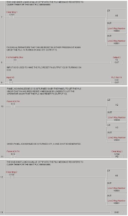
65 EZ-TEXT-M-E 61
, to the panel port and the PLC port. 1. Press the esc (escape) button on the EZSeries Set Point Display Text Panel.")
66 3. Save the Program to the PLC and to disk (EZSeries Set Point Display Text Panel DemoProject). 4. Place the PLC in Run Mode. The PLC is now configured and running. ow, to test our project, connect the Panel to PLC communications cable (P/ EZP-2CBL), to the panel port and the PLC port. 1. Press the esc (escape) button on the EZSeries Set Point Display Text Panel. The Local Message (folder), + Process Control, will be displayed on the first line. 2. Press the enter button to open the folder. Level 2 Local Message Press F1 to Start Y0 will be displayed. Use the (arrow) buttons to scroll through the messages. Press the esc button to go back to the Folder Level Press F1 to turn O or OFF Y0. 4. Press F2 to turn O Y1 for 5 seconds. 5. Press F3 to display PLC Message o Press F4 to turn O Y2. Either press F4 again to turn it OFF, or turn O X0 in the PLC. If the PLC turns OFF F4, a message will be displayed. 7. Press F5 to see an alternate button with flashing LED. COGRATULATIOS! You have now successfully configured an EZSeries Set Point Display Text Panel! 62 EZ-TEXT-M-E
67 Configuration 5 In this chapter... Configure ew System Step 1, Select Panel Step 2, Select PLC Step 3, Panel System PLC Address Setup Configure Local and PLC Messages Configure Existing System Connect to Panel, View Panel Status and Firmware Version Upgrade Firmware
68 This section will take you through the steps necessary to configure a new system, edit an existing system, view panel status, and upgrade the EZSeries Set Point Display Text Panel firmware. We recommend that you go through the tutorial in Chapter 4, page 43, before configuring your EZSeries Set Point Display Text Panel. If you don t already have the EZSeries Set Point Display Configure ew System 1. Click on the EZSeries Set Point Display Text Panel Icon to open the EZSeries Set Point Display Text Panel Programming Software. 64 EZ-TEXT-M-E


, and click on the Save button to save.")
69 The following screen will appear. 2. Click on the ew System button to configure the EZSeries Set Point Display Text Panel program. The following screen will appear. 3. Enter a name for the project in the File name field. avigate to the directory and folder where you want to keep the file (or except default location), and click on the Save button to save. The following screen will appear. EZ-TEXT-M-E 65


70 4. For Step 1, click on the Select Panel Type button. The following screen will appear. Under Panel Type, click on the model you are using. A Panel Preview and Panel Attributes specific to the type of panel you have chosen will appear in this dialog box. Click on OK to enter your selection. 5. For Step 2, click on the Down Arrow next to the Select PLC field. Choose the PLC and Protocol type you are using. 6. Click on Press for Communication Configuration for Selected PLC button. A PLC Attributes dialog box specific to your type PLC will appear. Complete the communications information. After selecting the PLC type, you must define the remaining protocol items, such as baud rate, parity, etc. The following table provides the necessary information for most DirectLogic controllers. When using another type PLC, consult that product s user manual to determine the port communications capabilities. 66 EZ-TEXT-M-E

71 Table for DirectLogic PLC Attributes During configuration, ensure that your address and communications parameters match the PLC port settings. There will be a selection for PLC timeout. When the panel sends a message to the PLC and does not receive a response or does not understand the response, it will wait the timeout period before sending the message again. EZ-TEXT-M-E 67
 Setup, enter the PLC Addresses for Line One and Line Two (and Line Three and Line Four if using an EZ-420 Model). Select the Data Type for the PLC.")
.")
72 7. For Step 3, click on the Configure Panel System PLC Addresses button. The Panel System PLC Address Setup window will appear. 8. Under PLC Messages (Line Address) Setup, enter the PLC Addresses for Line One and Line Two (and Line Three and Line Four if using an EZ-420 Model). Select the Data Type for the PLC. Select Yes or o to Enable Beeper. Click OK. 9. ext, click on the Buttons/LEDs button (shown to the right) to configure the Panel Functions. The following screen will appear. 10. If you want Password Protection, to restrict access to data entry, enter a Local Password (up to 5 digits, ). If you want to store the password in the PLC, enter a register address (PLC Password Register) and select the Data Type for the PLC. Click OK to exit the Setup screen. *Password Protection is only available in models EZ-220P & 220PV. 11. First select the LED Control for the first button LED, Bit 0. You may choose to have the LED controlled By Button, By Button & Flash, or By PLC. Make selections for Bit 0 through Bit 4. The LED function depends on the type of Button Action selected. By Button means that the LED illuminates when the button is pressed. By Button & Flash means that the LED illuminates and flashes when the button is pressed. By PLC means that the LED illuminates when triggered by the PLC. 12. Select the Button Action for each button Bit 0 through Bit 4 You may choose from Momentary, Alternate, or Panel Set and PLC Release. Momentary means that the Button is O only while the button is being pressed. Alternate means that the Button is turned O when pressed and only turns OFF when the button is pressed again. Panel Set and PLC Release means that the Button and LED are O when the button is pressed and turn OFF when pressed again or when turned off by the PLC. 68 EZ-TEXT-M-E
 or Bit 8 through Bit 12 (Decimal). The panel turns O these bits to acknowledge the PLC Release Bits. 12. Enter a LED (Bit Read) PLC Word and a Buttons (Bit Write) PLC Word address.")
73 PLC Button Release Bits use Bit 10 through Bit 14 (Octal) or Bit 8 through Bit 12 (Decimal). If the button is O, the PLC can release the button by setting the corresponding release bit. Panel Acknowledge of PLC Release Bits use Bit 10 through Bit 14 (Octal) or Bit 8 through Bit 12 (Decimal). The panel turns O these bits to acknowledge the PLC Release Bits. 12. Enter a LED (Bit Read) PLC Word and a Buttons (Bit Write) PLC Word address. 13. Click on OK to save your Button/LED control selections. 14. ow you are ready to configure Local and PLC Messages. Click on the Message button (as shown to the right). The following screen will appear. 19. For Step 1, choose to confi gure a Local or PLC Message. Local Messages are messages stored in the panel in a menu hierarchy and provide information and instructions to the operator. PLC Messages are triggered by a value in a PLC register. The PLC Message LED will illuminate to tell the operator that the PLC has triggered a message. The buttons will not respond for 3 seconds after the PLC Message has been triggered to ensure that the operator has a chance to read the EZ-TEXT-M-E 69


74 message. See step 16 (next step) to program a PLC Message. To program a Local Message, perform the following steps. a. ext to Local Messages, click on the Add Local Folder button or the Add Local Message Button. b. Under Step 2, type in up to 20 characters in the Message Text field. This register controls LEDs and PLC Button Release (Read Only or Read/Write address) This register controls Buttons and Panel Acknowledge (must be READ/ WRITE address) c. Step 3, click on the Press to Accept Message Edit button. The message text you have typed in will appear in the Local Message field. d. If you want to embed data from a PLC register in a Local Message, place the cursor in the message where you want the value to appear and press F5 or ( CTRL+1) for DATA 1, F6 or ( CTRL+2) for DATA 2, or F7 or ( CTRL+3) for DATA 3. Each press of the function key will enter one data value digit. You may enter up to 5 characters (depending on the data type). In the message, the data will be represented by red 1 s for DATA 1, blue 2 s for DATA 2, and green 3 s for DATA 3. (The actual value will display in the message on your EZSeries Set Point Display Text Panel.) e. ow you will need to configure the embedded data. If you have embedded data, you will notice that the DATA 1, DATA 2, or DATA 3 field is now available. f. You must first enter the PLC Address where the value resides. Select the Data Type ( format) for your PLC Type (either BCD or Binary). g. Select the Access for the PLC register. Will you want the message to display a register value (READ only)? Do you want the message to display a register value and allow the operator to change the 70 EZ-TEXT-M-E
 field.")

75 *15. ow you are ready to configure the Annunciator Lamps. Click on the Annunciator Button, shown below. The following screen will appear. *16. Enter a PLC address in the PLC Read Word (Bits) field. When you configure the PLC ladder logic, use the bit assignments as shown in the dialog box above to control the three annunciator lamps. (White represents OFF.) *17. Click on the OK button to save the register address and exit the screen. *18. ow you are ready to configure Local and PLC Messages. Click on the Message button (as shown to the right). The screen at the top of the following page will appear. *These features available in models EZ-220P & EZ-220PV only. EZ-TEXT-M-E 71


76 value with the panel ARROW Keys (READ/WRITE)? h. If you select READ/WRITE Access, you can enter a Minimum and Maximum Range that the operator can write to the PLC. i. You will notice that Password Protection is not available for the EZSeries Set Point Display Text Panel models covered by this manual. Password Protection is only available in the EZ-220P model, that offers a keypad for numerical data entry. j. You may confi gure DATA 1 to display a decimal point that is controlled by the PLC. The location of the decimal point must be configured in your PLC ladder logic program. Place a check Click on this button to add a folder Click on this button to add a message OTE: Folders can have up to 19 characters maximum. mark in the box next to PLC Controlled Decimal Point and then enter the PLC Address where the control resides. (This is DATA 1 only you cannot configure PLC Control for a DATA 2 or DATA 3 embedded value.) If PLC control for the decimal point is enabled, the program will place a decimal point at the end of the characters representing the 1 Enter text here 2 Click here to accept text 3 Configured Message will appear here Total characters in current message is shown here data value in the Message Text field in the figure above. Then placing a value of 1 4 (BCD) or 1 5 (Decimal) in the PLC 72 EZ-TEXT-M-E


77 register will place the decimal in the appropriate location. k. You may manually enter a decimal point in DATA 1, DATA 2 or DATA 3, by placing your cursor in the message where you want it to appear in the value, and then insert the decimal point as shown below. l. Create Folders to group messages relating to the same topic. The first message or folder you program will appear on the first line of the EZSeries Set Point Display Text Panel display when it is in Run Mode. (Second programmed message displays on second line, etc., up to four lines, depending on the type of panel you are using.) The Local Message and Folder menu tree can have up to 3 levels as shown in the following example. m. To add a folder, click on the Add Local Folder button. n. To insert a Message or Folder between already configured messages, you must first have a message or folder highlighted. click on Insert Folder or Insert Message. The inserted Message or Folder will be placed above the highlighted Message or Folder. EZ-TEXT-M-E 73
78 o. To delete a Message or Folder, click on it to highlight it and then click on the Delete button. p. To save your messages and exit the Message Edit window, click on the OK button at the bottom of the Message Edit window. To exit without saving, click on the Cancel button. 20. PLC Messages are triggered by a value in a PLC register. The PLC Message LED will illuminate to show the operator that the PLC has triggered the message. To program a PLC Message, click on the Add ext PLC Message button. a. Type in text up to 20 characters in the Message Text field. The 20 character maximum includes Data Items, also, if you choose to enter them. You will see the Message Length value change as you enter characters to let you know how many you have used. The current Message umber and Total umber of Messages (of 256) programmed are also displayed for your information. b. If you want to embed data values from a PLC register in the message, press F5 or (Ctrl+1) for DATA 1, F6 or (Ctrl+2) for DATA 2, or F7 or (Ctrl+3) for DATA 3. Each press of the function key will enter 1 data value character. You may enter up to 5 characters depending on the data type you have selected. c. You will configure Data 1, Data 2, and Data 3 values the same way as described in a Local Message. d. If you have configured messages out of sequence and you want to insert a message between messages already programmed, click on Insert a PLC Message. Be aware that blank messages count in the Total Messages allowed. For example: You have programmed PLC Messages numbered 001, 002 and 004, skipping PLC Message number 003, as shown below. Click on 004: PLC Message 4 in the message field to highlight it, and then click on the Insert a PLC Message button. PLC Message umber 003 will appear above PLC Message umber 004 and you may enter the new message. 74 EZ-TEXT-M-E


79 Be aware that when programming messages out of sequence, that the blank messages are counted in the Total Messages allowed. The following CAUTIO message will appear when you enter a message number higher than the next number in sequence. If you have skipped more than one message number (e.g., you have programmed messages 1 through 4, skipped messages 5, and 6, and then programmed 7), and highlight message 7 and click on Insert a PLC message, the following dialog box will appear asking you to enter the number (e.g., 5 or 6) of the message you want to insert. e. To delete a message, click on it to highlight and then click on the Delete button. 21. To view the PLC Addresses you have programmed click on the Panel PLC Address Database button. The following window will open. EZ-TEXT-M-E 75

80 76 EZ-TEXT-M-E


81 EZ-TEXT-M-E 77

82 Shown here will be the addresses mapped to the panel display lines (Line one, Line two, etc.), the Bit Write (Buttons), Bit Read (LEDs), and the PLC Message Data Items. Items grayed out are not available for the EZSeries Set Point Display Text Panel model you have selected. The PLC/controller you have selected and the Project ame are also displayed, along with the Total umber of messages (OUT OF 256) programmed. This is for information only to edit the addresses, click on the EDIT PAEL SYSTEM PLC ADDRESSES button. 22. Click on the Print button to print the database or the OK button to exit. 78 EZ-TEXT-M-E

83 Configure Existing System 1. Click on the EZSeries Set Point Display Text Panel Icon to open the EZSeries Set Point Display Text Panel Programming Software. The following screen will appear. 2. Click on the Existing System button to edit an EZSeries Set Point Display Text Panel program. The following screen will appear. EZ-TEXT-M-E 79

84 Connect to Panel, View Panel Status and Firmware Version Click on the Connect to Panel, View Panel Status & Firmware Version button to view the panel status. The Panel Status window will open. An example is shown below. Picture of the panel type you are connected to Key features of the current panel Panel and PLC information is displayed, including panel model, Firmware Revision, Memory Size, PLC Driver, and PLC Driver Revision number 80 EZ-TEXT-M-E


85 Upgrade Firmware There may be occasional upgrades to the EZSeries Set Point Display Text Panel internal software, also referred to as the Exec or Firmware. Check the EZAutomation web site periodically for information about software and firmware upgrades. To Upgrade Firmware: 1. Place the panel in Setup Mode by pressing the UP/DOW arrows on the EZSeries Set Point Display Text Panel simultaneously. 2. Under the Panel Menu, click on Upgrade Firmware. The following screen will appear. 3. Click on the Browse button. The window, shown to the right, will open to the default folder, Firmware (located in the EZSeries Set Point Display Text Panel Program directory). If the firmware file has been downloaded from the EZAutomation website to another location, navigate to the new firmware file (.hex file). EZ-TEXT-M-E 81
 for the different types of EZSeries Set Point Display Text Panels: EZ220xy for the EZ-220 & EZ-220V panels; EZ220Lxy for the EZ-220L panel; EZ420xy for the EZ-420 panel; EZ220Pxy for EZ-220P &")
86 There are five types of firmware files (.hex) for the different types of EZSeries Set Point Display Text Panels: EZ220xy for the EZ-220 & EZ-220V panels; EZ220Lxy for the EZ-220L panel; EZ420xy for the EZ-420 panel; EZ220Pxy for EZ-220P & EZ-220PV panels (not covered in this manual); and the EZSPPxy for the EZ-SP Set Point Panel (also, not covered in this manual). The x represents the major revision of the firmware (e.g., A). y represents the minor revision (e.g., 1). Make sure that you select the correct firmware.hex file for your type panel, and send the upgrade to the panel. 4. Select the appropriate COM port under Port Selected (if necessary) and click on the Start button to begin downloading the firmware to the EZSeries Set Point Display Text Panel. A status bar will let you know when the upgrade is complete. Click on Close when complete. When you initialize the Upgrade Firmware process, the EZSeries Set Point Display Text Panel Message display will read SELF TESTIG. When the download begins, the display will read LOADIG EXEC. When the download is complete, the panel will enter the Run Mode. If the message ICOMPATIBLE EXEC is displayed on the panel while the Upgrade is in process, it means that the wrong firmware file has been sent to the panel. You will also receive an error message from the EZSeries Set Point 82 EZ-TEXT-M-E
87 Display Text Panel Programming Software, as shown below. If this happens, do the following: 1. Click on the OK button on the Error Message. 2. Click on the Cancel button on the Downloading Firmware window. Upgrade Firmware, when you press the Start button, the panel will display SELF TESTIG while the upgrade is initializing. When the download begins, the panel will display LOADIG EXEC. If you get the message, ICOMPATIBLE EXEC, you have sent the wrong firmware file. Exit all windows and start the Upgrade EZ-TEXT-M-E 83
88 This page intentionally left blank. 84 EZ-TEXT-M-E
89 Maintenance & Troubleshooting 6 In this chapter... Maintenance Fuse Reset Precautions Screen Overlay/Chemical Compatibility Screen Overlay Cleaning Gasket Replacement Troubleshooting Panel Confi guration Problems PLC Errors Warranty Repairs Out of Warranty Repairs Frequently Asked Questions (FAQs)
90 Maintenance Fuse Reset The EZSeries Set Point Display Text Panel features an AUTO-RESET fuse (0.65 Amp polyfuse). It is reset by removing power for 5 minutes and then reapplying power to the unit. Precautions To ensure the longevity and effectiveness of the EZSeries Set Point Display Text Panel, please take note of the following precautions: Do not press sharp objects against the pushbuttons or screen overlay. Do not strike the panel with hard objects. Do not press the pushbuttons or screen overlay with excessive force. Once the panel is mounted and has power applied, do not place any objects over the ventilation slots. This will result in heat buildup and may damage the unit. Screen Overlay/ Chemical Compatibility The screen overlay has a polycarbonate surface. The following list is provided to make you aware of the general compatibility between chemicals that may be present in your work environment and the polyester surface of the overlay. Use the chart to determine those chemicals that are safe to use around your EZSeries Set Point Display Text Panel and those that may harm the overlay. The list rates these chemicals as E Excellent, G Good, F Fair, and ot Recommended. Because the ratings are for conditions at 134 F (57 C), co Screen Overlay Cleaning CHEMICAL RATIG CHEMICAL RATIG Acetaldehyde Acetamide Acetic 5% Acetic 50% Acetone Acetonitrile Acrylonitrile Adipic Acid Alanine Allyl Alcohol Alum. Hydroxide Aluminum Salts Amino Acids Ammonia Ammonium Acetate Ammonium Gloclate G G E F G E E F Ammonium 5% Ammonium 30% Ammonium Oxalate Ammonium Salts n-amyl Acetate Amyl Chloride Aniline Benzaldehyde Benzene Benzoic Acid Benzyl Acetate Benzyl Alcohol Bromine Bromobenzene Bromoform Butadiene E G G G G F 86 EZ-TEXT-M-E
91 CHEMICAL RATIG CHEMICAL RATIG n-butyl Acetate n-butyl Alcohol F sec-butyl Alcohol F tert-butyl Alcohol F Butyric Acid Calcium Hydroxide Calcium Hypochlorite Carbazole Carbon Disulfi de Carbon Tetrachloride Cedarwood Oil F Cellosolve Acetate 10% in air G 10% moist F Chloroacetic Acid p-chloroacetophenone Chloroform Chromic 10% Chromic 50% Cinnamon Oil F Citric 10% G Cresol Cyclohexane G Decalin o-dichlorobenzene p-dichlorobenzene Diethyl Benzene Diethyl ether Diethyl Ketone Diethyl Malonate Diethylene Glycol F Diethylene Glycol Ethyl Ether Dimethylformamide Dimethyl Sulfoxide 1, 4-Dioxane F Dipropylene Glycol F Ether Ethyl Acetate Ethyl Alcohol G Ethyl 40% G Ethyl Benzene Ethyl Benzoate Ethyl Butyrate Ethyl Chloride Liquid Ethyl Cyanoacetate Ethyl Lactate Ethylene Chloride Ethylene Glycol F Ethylene Glycol Methyl Ether Ethylene Oxide Fluorides Fluorine Formaldehyde 40% Formic 3% Formic 50% Formic 99% Fuel Oil Gasoline Glacial Acetic Acid Glycerin n-heptane Hexane Hydrochloric 5% Hydrochloric 20% Hydrochloric 35% Hydrofluoric 5% Hydrofluoric 48% Hydrogen 5% Hydrogen 30% Hydrogen 90% Isobutyl Alcohol Isopropyl Acetate Isopropyl Alcohol Isopropyl Benzene Kerosene Lactic 3% Lactic 85% Methoxyethyl Oleate Methyl Alcohol Methyl Ethyl Ketone Methyl Isobutyl Ketone Methyl Propyl Ketone Methylene Chloride Mineral Oil itric 10% itric 50% itric 70% itrobenzene n-octane Orange Oil Ozone Perchloric Acid Perchloroethylene Phenol Crystals Phosphoric 5% Phosphoric 85% Pine Oil E F G G G F G F E G E F F E E E G E E G G F G G F F F G E G E EZ-TEXT-M-E 87
92 CHEMICAL RATIG CHEMICAL RATIG Potassium 1% Potassium Hydroxide conc. Propane Gas Propylene Glycol Propylene Oxide Resorcinol sat. 5% Salicylaldehyde Salicylic Acid Powder Salicylic Acid sat. Salt Solutions Metallic Silver Acetate Silver itrate Sodium Acetate sat. Sodium 1% Sodium 50%+ Sodium 15% Stearic Acid Crystals Sulfuric 6% Sulfuric 20% Sulfuric 60% F F F F F G G E G E G F G E G F Sulfuric 98% Sulfur Dioxide Liquid Sulfur Dioxide dry Sulfur Salts Tartaric Acid Tetrahydrofuran Thionyl Chloride Toluene Tributyl Citrate Trichloroethane Trichloroethylene Triethylene Glycol Tripropylene Glycol Turpentine Undecyl Alcohol Urea Vinylidene Chloride Xylene Zinc Stearate G G G G G F E The EZSeries Set Point Display Text Panel screen should be cleaned as needed with warm, soapy water. Gasket Replacement The gasket may need to be replaced if it becomes damaged or worn. To replace the gasket, use P/ EZ-TEXT-S-GSK for the small models, EZ-220 and EZ-420. Use P/ EZ-TEXT-L-GSK for the large model (EZ-220L). To replace the gasket perform the following steps: 1. The gasket is removed and replaced from the back of the unit. Ensure that all pieces of old gasket have been removed from the panel enclosure surface where the gasket is affixed. 2. Remove the new replacement gasket from its plastic bag. 3. Remove the temporary protective covering from the adhesive side of the gasket. 4. Position gasket ( adhesive side down) over the panel gasket surface and press firmly. In this section we will explain how to isolate potential problems. If you cannot 88 EZ-TEXT-M-E

93 Troubleshooting isolate and remedy the problem using the procedures we have outlined below, call technical support. For a list of EZSeries Set Point Display Text Panels, EZSeries Set Point Display Text Panel Programming Software, and PLC Driver Error Messages, see Appendix C. Panel Configuration Problems EZSeries Set Point Display Text panel Programming Software is used to create panel applications and to download/upload panel programs. If you are online with the EZSeries Set Point Display Text Panel and communication fails, the following error message is displayed: If you receive this EZSeries Set Point Display Text Panel Programming Software error message, check the following: 1. On the rear panel of the unit, observe Serial Port Communication TXD/ RXD LEDs while attempting to Upload/Download a program. Both LEDs should be slowly and alternately flashing to indicate that the programming PC and the panel are connected. If the TXD (transmitter) LED is the only one flashing, or if the TXD/RXD LEDs are OT alternating between flashes, check to ensure that the EZSeries Set Point Display Text Panel is set to the Setup (programming) Mode. (To enter the Setup Mode, press and hold the UP Arrow Button while simultaneously pressing the DOW Arrow button.) 2. Check to ensure that the programming cable (part number EZTEXT-PGMCBL) is properly connected at both ends. 3. Check that the correct communications port is selected with the EZSeries Set Point Display Text Panel Programming Software (i.e., COM1, COM2) 4. Check the 24 VDC power source and its connections. EZ-TEXT-M-E 5. After completing steps 1 through 4, above, repeat the procedure to 89


94 Upload/Download a program. PLC Errors If you experience communication problems between the EZSeries Set Point Display Text Panel and your PLC, you will receive an error message that is unique to that particular PLC. Look in the Appendix C of this manual, or the EZSeries Set Point Display Text Panel Programming Software Help for error messages for your type PLC. Each PLC Help topic lists the error messages and provides an explanation for each PLC driver. To access the PLC Help topics, perform the following steps. a. Run EZSeries Set Point Display Text Panel Programming Software. b. From the Main Menu, click on Help > Help Topics. c. Under the Contents tab, find the type PLC you are using (next to a 90 EZ-TEXT-M-E
In this chapter... Manual Organization Introduction to the EZText Panel What you need to get started Need HELP? Models PLCs Supported by EZText Panel
 Introduction 1 In this chapter... Manual Organization Introduction to the EZText Panel What you need to get started Need HELP? Models PLCs Supported by EZText Panel Accessories and Optional Equipment PLC
EZText Enhanced User Manual Models: EZ-220, EZ-220V, EZ-220L, EZ-420, EZ-220P, & EZ-220PV Manual Part Number EZ-TEXT-M-E
 EZText Enhanced User Manual Models: EZ-220, EZ-220V, EZ-220L, EZ-420, EZ-220P, & EZ-220PV Manual Part umber EZ-TEXT-M-E This page intentionally left blank. The Most Sensible Automation Products Direct
Hardware Installation. In this chapter... Custom Labels EMI Noise Filter Installation Mounting DIN Clip Mounting Connections and Wiring
 Hardware Installation 2 In this chapter... Custom Labels EMI Noise Filter Installation Mounting DIN Clip Mounting Connections and Wiring Custom Labels Create Custom Labels You may create custom labels
EZText Panel User Manual Models: EZ-220, EZ-220-DEV, EZ-220L, EZ-220L-DEV, EZ-420, and EZ-420-DEV. Manual Part Number EZ-TEXT-M
 EZText Panel User Manual Models: EZ-220, EZ-220-DEV, EZ-220L, EZ-220L-DEV, EZ-420, and EZ-420-DEV Manual Part umber EZ-TEXT-M WARIG! Programmable control devices, such as EZText Panels, must not be used
Learning the Features
 Learning the Features 3 In this chapter... Learning the Features Memory Mapping/PLC Data Registers Pushbuttons LEDs PLC Message Embedded Data PLC and Local Messages Message Types Displaying PLC Messages
EZ Touch Plus. Copyright 2014 by AVG Automation. All Rights Reserved.
 Copyright 2014 by AVG Automation. All Rights Reserved. Table of contents Warnings... 3 Product Overview... 4 Specifications... 5 Installation... 6 Mounting Information... 6 Powering the Unit... 8 Communication...
User Memory. Touch Panel. Touch Panel with Slim Bezel. Touch Panel. Touch Panel. Touch Panel with Slim Bezel. Touch Panel with Slim Bezel.
 Models The EZ is an intelligent, programmable, flat panel display. It has been designed to interchange and display graphical data from a PLC by merely viewing or touching the screen. The EZ is available
Tough Panel Plus 15"
 15" Copyright 2014 by AVG Automation. All Rights Reserved. Table of contents Warnings... 3 Product Overview... 4 Specifications... 5 Installation... 6 Mounting Information... 6 Powering the Unit... 8 Communication...
C-more Micro-Graphic Panel Accessories
 8-Button Keypad Bezel The 8-button keypad bezel can be used with both the touch and non-touch Micro-Graphic panels. The keypad includes four directional arrow cursor buttons, and one each of an ESCAPE,
4 INSTALLATION. Installing the EZTouch Panel requires the following three major steps:
 Installing the EZTouch Panel requires the following three major steps: Mounting Connections and Wiring Communications Setup The EZTouch Panel is a front-panel mount unit. Mounting of the unit requires
Getting Started. In This Chapter... Introduction OP-1500/OP-1510 Overview Frequently Asked Questions
 In This Chapter.... Introduction OP-1500/OP-1510 Overview Frequently Asked Questions 1 2 Introduction The Purpose of this Manual Contents of the Manual This User Manual provides user information on panel
C-more 3 Micro-Graphic STN Touch Panel
 R 3 Micro-Graphic STN Touch Panel This Touch Screen version of the Micro-Graphic panel has a 3.1-inch STN LCD monochrome display. Model EA1-S3ML has five selectable LED-driven backlight colors: Green,
i 2 Index Communications Ports, 2 6 Conventions Used, 1 3 exclamation mark, 1 3 notepad, 1 3
 INDEX A Accessories, 3 2 EA-6-COV2, 3 2, 3 15 EA-MG-PGM-CBL, 3 2, 3 6, 3 7 EA-MG-PGMSW, 3 2 EA-MG6-BZ2, 3 2, 3 9 EA-MG6-BZ2P, 3 2, 3 11, 3 12 Agency Approvals, 1 4 Available Models, 2 2 C C-more Micro-Graphic
Index EA-USER-M Hardware User Manual, 2nd Ed. Rev. H, 05/18 i-2
 6 Adapter Plate, 4 9 6 Adapter Plate Assembly, 3 18 6 Adapter Plate Cutout Dimensions, 3 17, 4 10 6 Adapter Plate Dimensions, 3 17, 4 10 6 Adapter Plate Installation, 3 18 A AC Wiring Diagram, 4 14 AC/DC
PanelView Plus/VersaView CE Terminals and Display Modules
 Installation Instructions PanelView Plus/VersaView CE Terminals and Display Modules (Catalog Numbers 2711P-xxxxxx, 6182H-xxxxxx) English Inside: Overview...2 For More Information...2 Modular Components...3
Appendix A Example Programs
 Appendix A Example Programs Understanding the Example Programs One of the best ways to learn how to use the OP-panel is to load the example programs which are on the supplied diskette, and run the program
C-more Micro-Graphic Power Connection Wiring
 Computer Programming Connections Using the Programming Software for project development, the panel can be connected to a PC (personal computer) by using EA-MG-PGM-CBL, the USB-to- cable assembly. Connect
C-more Micro-Graphic Specifications
 Micro-Graphic Specifications Specification Model 3 STN Micro-Graphic Panel Touch Screen 3 STN Micro-Graphic Panel Non-Touch Screen Part Number EA1-S3ML EA1-S3ML-N Description 128 x 64 dots LCD display,
Installing the Panel. Installing the Panel
 7 In this section you will be given all of the information you need to install the panel. Before actually installing the OP- panel, it may be helpful to examine the specifications and make sure that the
Weight ounces Panel Fasteners... Four holes to accept four 16x32 machine screws NEMA Rating... NEMA 1
 8 Panel Specifications: In this section, you will be given all of the information you need to install the panel. Before actually installing the OP-9001 panel, it may be helpful to examine the specifications
Getting Started. In This Chapter... Introduction Conventions Used OP-420 Overview Frequently Asked Questions
 In This Chapter.... Introduction Conventions Used OP-420 Overview Frequently Asked Questions 1 2 Introduction The Purpose of this Manual Thank you for purchasing an OP 420 OptiMate panel. This User Manual
Vertiv Local Rack Access 18.5" LED LCD Console
 Vertiv Local Rack Access 18.5" LED LCD Console With Integrated Keyboard, Touchpad and Dual USB 2.0 Ports Installer/User Guide Technical Support Site If you encounter any installation or operational issues
PWS500S Installation Guide
 PWS500S Installation Guide F-1 Introduction The PWS500 is equipped with a 3.0" sized (160Hx80V) flat panel display and analog resistive touch screen. The IP 65 (NEMA 4) rated front panel seal and INDUSTRIAL
Programming Software Version 4.0 User Manual. (Manual P/N MAN-UTICW-M)
") Programming Software Version 4.0 User Manual (Manual P/N MAN-UTICW-M) WARNING! Programmable control devices such as the G 2 Series PowerPanel must not be used as stand-alone protection in any application.
Programming Software Version 4.0 User Manual (Manual P/N MAN-UTICW-M) WARNING! Programmable control devices such as the G 2 Series PowerPanel must not be used as stand-alone protection in any application.
Certification according to CE. C-more Touchpanels:
 The new Generation of Touch Panels with ambitious image presentation and integrated operating function With the C-more series, featuring STN and TFT touch screens, AutomationDirect now provides the best
Artisan Technology Group is your source for quality new and certified-used/pre-owned equipment
 Artisan Technology Group is your source for quality new and certified-used/pre-owned equipment FAST SHIPPING AND DELIVERY TENS OF THOUSANDS OF IN-STOCK ITEMS EQUIPMENT DEMOS HUNDREDS OF MANUFACTURERS SUPPORTED
Certification according to CE. C-more Touchpanels:
 The new Generation of Touch Panels with ambitious image presentation and integrated operating function With the C-more series, featuring STN and TFT touch screens, AutomationDirect now provides the best
P3-RS Remote Slave Module
 P3-RS Rack with CPU Module Racks with P3-RS Modules The P3-RS is a full-featured, highperformance, Remote Slave module. Features include a line x 0 charactor LCD display and five communications ports
PACSystems RX7i IC698CHS009/119
 January 2010 The RX7i rack can be used for all RX7i CPU and I/O configurations, Series 90-70 I/O, and VME modules. Backplane connectors are spaced on 0.8" (20.3mm) centers to accommodate single-width RX7i
EXPRESS SETUP. PanelMate 1700 Series PanelMate Power Pro. Cutler-Hammer
 EXPRESS SETUP PanelMate 1700 Series PanelMate Power Pro Cutler-Hammer Installation Unpacking Carefully remove all equipment from the packing cartons and inspect all parts for damage in shipment. Check
user and installation manual
 SI3500 SI3500 ORBIT Digital Display The SI3500 is a member of the SI3000 Readout Family. All members of the family are marked SI3000 on the front panel. This manual is specifically for the SI3500 Model
Installation Guide V290 (Color) This guide provides basic information for Unitronics LCD color touchscreen models V C30B and V T40B.
 This guide provides basic information for Unitronics LCD color touchscreen models V C30B and V T40B.") Vision OPLC Installation Guide V290 (Color) This guide provides basic information for Unitronics LCD color touchscreen models V290-19-C30B and V290-19-T40B. General Description Vision OPLCs are programmable
Vision OPLC Installation Guide V290 (Color) This guide provides basic information for Unitronics LCD color touchscreen models V290-19-C30B and V290-19-T40B. General Description Vision OPLCs are programmable
C-more Selection Guide & Specifications
 Selection Guide & Specifications Model 8 TFT color 10 TFT color 12 TFT color 15 TFT color Specification Part Number EA7-T8C EA7-T10C EA7-T12C EA7-T15C Price Display Actual Size and Type 8.4" TFT color
APPENDIX B SERIAL I/O MODULE INSTALLATION / OPERATION WHEN USING T&D VER. 5.2 OR 5.3
 SERIAL I/O MODULE INSTALLATION / OPERATION WHEN USING T&D VER. 5.2 OR 5.3 APPENDIX B In This Appendix... H2 SERIO(-4) Overview................................B 2 Specifications........................................B
This guide provides basic information for Unitronics Models 230/260/280/290 (Non-color Screens).
.") Vision OPLC Installation Guide Models 230/260/280/290 (Non-color Screens) This guide provides basic information for Unitronics Models 230/260/280/290 (Non-color Screens). General Description Vision OPLCs
Vision OPLC Installation Guide Models 230/260/280/290 (Non-color Screens) This guide provides basic information for Unitronics Models 230/260/280/290 (Non-color Screens). General Description Vision OPLCs
C-more Selection Guide & Specifications
 Selection Guide & Specifications Model 8 TFT color 10 TFT color 12 TFT color 15 TFT color Specification Part Number EA7-T8C EA7-T10C EA7-T12C EA7-T15C Price $975.00 $1,575.00 $1,875.00 $2,275.00 Display
SI3300. user and installation manual. 4-20mA/DC-Digital Display
 SI3300 4-20mA/DC-Digital Display The SI3300 is a member of the SI3000 Readout Family. All members of the family are marked SI3000 on the front panel. This manual is specifically for the SI3300 Model with
Dataliner DL40 Plus Message Displays
 Release Note Dataliner DL40 Plus Message Displays The Dataliner DL40 Plus Message Displays, the next generation of Allen-Bradley message displays, directly replace the Dataliner DL40, DL20 and DL10 Series
P3000 PowerMarquee Master Display Hardware User Manual. (Manual Part Number MAN-P )
") P3000 PowerMarquee Master Display Hardware User Manual (Manual Part Number ) WARNING! Programmable control devices such as UTICOR s P3000 PowerMarquee Master, must not be used as stand-alone protection
P3000 PowerMarquee Master Display Hardware User Manual (Manual Part Number ) WARNING! Programmable control devices such as UTICOR s P3000 PowerMarquee Master, must not be used as stand-alone protection
SMIC Smart Cable Installation and Connection Guide
 SMIC Smart Cable Installation and Connection Guide Kessler Ellis Products 10 Industrial Way East Eatontown, NJ 07724 Phone: 732-935-1320 Fax: 732-935-9344 www.kep.com 99719REV21JAN02 $5.00 0 About this
Optional Accessories 6 2
 Accessories Chapter 6 Table of Contents Optional Accessories 6 2 Finger Guards 6 2 Remote Touchscreen 6 3 RJ45 to RJ12 Adapter 6 5 Serial Modbus Communication Splitter 6 5 Communication Modules 6 7 Replacement/Spare
3700 SERIES USER MANUAL
 SAFETY GUIDE This manual contains the precautions necessary to ensure your personal safety as well as for protection for the products and the connected equipment. These precautions are highlighted with
MAINTENANCE MANUAL. EDACS REDUNDANT POWER SUPPLY SYSTEM 350A1441P1 and P2 POWER MODULE CHASSIS 350A1441P3, P4, AND P5 POWER MODULES TABLE OF CONTENTS
 MAINTENANCE MANUAL EDACS REDUNDANT POWER SUPPLY SYSTEM 350A1441P1 and P2 POWER MODULE CHASSIS 350A1441P3, P4, AND P5 POWER MODULES TABLE OF CONTENTS SPECIFICATIONS*... 2 INTRODUCTION... 3 DESCRIPTION...
Bulletin 2707 DTAM Plus Operator Interface Product Data
 A B Product Data Overview The DTAM Plus devices offer a highly functional operator interface to both Allen-Bradley PLC and SLC processors. This proven interface provides operators with the convenience
PLC Racks IC697CHS782/783
 5 1 PLC Racks IC697CHS782/783 (IC697CHS782/783) datasheet Features Accepts 3rd Party VME modules which require 0.8 spacing. Accepts all IC697 PLC module types. Rear mount rack mounts in a 10 (254 mm) deep
Torque Series LCD Remote Panel Installation/Operation Manual Model: TQ-DSP-12/24
 Torque Series LCD Remote Panel Installation/Operation Manual Model: TQ-DSP-12/24 Section Page Introduction 1 Materials Provided 1 I) Safety Instructions 1 A) Inverter Safety Instructions 1 B) Battery Safety
OP Setpoint/Display Panel. Manual Number OP M
 OP--32 Setpoint/Display Panel Manual Number OP--32--M WARNING Thank you for purchasing automation equipment from PLCDirect. We want your new DirectLOGIC automation equipment to operate safely. Anyone who
Datapanel. Datapanel 40/45, 60/65 & 85. Operator Interface Products. User's Manual
 Datapanel Operator Interface Products Datapanel 40/45, 60/65 & 85 User's Manual GFK-1806A Nov. 2001 Warnings, Cautions, and Notes as Used in this Publication Warning Warning notices are used in this publication
Allen-Bradley. Dataliner DL5 Slave Displays (Cat. No D11JS, -D21JS) User Manual
 User Manual") Allen-Bradley Dataliner DL5 Slave Displays (Cat. No. 2706-D11JS, -D21JS) User Manual Important User Information Because of the variety of uses for the products described in this publication, those responsible
Allen-Bradley Dataliner DL5 Slave Displays (Cat. No. 2706-D11JS, -D21JS) User Manual Important User Information Because of the variety of uses for the products described in this publication, those responsible
Installation Guide V290 (Color) This guide provides basic information for Unitronics LCD color touchscreen models V C30B and V T40B.
 This guide provides basic information for Unitronics LCD color touchscreen models V C30B and V T40B.") Vision OPLC Installation Guide V290 (Color) This guide provides basic information for Unitronics LCD color touchscreen models V290-19-C30B and V290-19-T40B. General Description Vision OPLCs are programmable
Vision OPLC Installation Guide V290 (Color) This guide provides basic information for Unitronics LCD color touchscreen models V290-19-C30B and V290-19-T40B. General Description Vision OPLCs are programmable
TRC-190 User s Manual
 User s Manual Edition 3.2, May 2017 www.moxa.com/product 2017 Moxa Inc. All rights reserved. User s Manual The software described in this manual is furnished under a license agreement and may be used only
Vision OPLC. General Description. Standard Kit Contents. Installation Guide Vision120. This guide provides basic information for Unitronics Vision120.
 Vision OPLC Installation Guide Vision120 This guide provides basic information for Unitronics Vision120. General Description V120 OPLCs are micro-oplcs, rugged programmable logic controllers that comprise
Introduction. Getting Started. Getting Started. D2 HPP Handheld Programmer
 1 2 Introduction D2 HPP Handheld Programmer The D2 HPP (Handheld Portable Programmer) is a general purpose tool for use with the DL105 or DL205 PLC products. It is well suited for performing basic PLC
TRC-190 User s Manual
 First Edition, November 2008 www.moxa.com/product 2008 Moxa Inc. All rights reserved. Reproduction without permission is prohibited. The software described in this manual is furnished under a license agreement
TD-700 FLUOROMETER SERVICE MANUAL
 TD-700 FLUOROMETER SERVICE MANUAL July 1996 CONTENTS Page Section 1 INTRODUCTION 2 Section 2 PRELIMINARY CHECKS 3 Section 3 TROUBLESHOOTING GUIDE 5 A. Lamp (Fluorescent) 5 B. Lamp Heater 7 C. Fan 8 D.
Adapter Kit for PanelView 1200/1200e Touch Screen Terminal Cutout
 Installation Instructions Adapter Kit for PanelView 1200/1200e Touch Screen Terminal Cutout Catalog Numbers 2711-NR5T, 2711P-RAT12E2 Topic Page About This Publication 1 Important User Information 2 About
ViewPoint II Operator Interface
 ViewPoint II Operator Interface Installation and Setup Manual ViewPoint II Front View (full scale) Industrial Control Links, Inc. 12840 Earhart Ave. Auburn, CA 95602 www.iclinks.com 530-888-1800 ViewPoint
2562 QUICK START GUIDE
 2562 QUICK START GUIDE CTI P/Ns: 2562 Quick Start Guide: 062-00348-010 2562 Installation and Operation Guide: 062-00332-011 Summary: The 2562 is designed to translate a digital word from the programmable
PWS3260 Installation Guide
 PWS3260 Installation Guide Introduction The PWS3260 is equipped with a 10.4" VGA sized (640Hx480V) flat panel display and analog resistive touch screen. The IP 65 (NEMA 4) rated front panel seal and industrial
When any of the following symbols appear, read the associated information carefully. Symbol Meaning Description
 Vision OPLC V350-35-R34/V350-J-R34 Installation Guide The Unitronics V350-35-R34/V350-J-R34 offers the following onboard I/Os: 22 Digital Inputs, configurable via wiring to include 2 Analog and 3 HSC/Shaft-encoder
Product RS stock no. Mitsubishi no. Description and features Display FX-40DU-E LCD display and function keys directly connected into FX PLC
 Data Pack D Issued March 1997 232-6118 Data Sheet Man machine interface display Mitsubishi FX PLC Supplied to RS by Mitsubishi Electric (UK) Ltd This fully interactive man machine interface display is
STR-3 STANDARD 3-PHASE 230 VAC TRANSFORMER CONTROLLER. Mounting and operating instructions
 STANDARD 3-PHASE 230 VAC TRANSFORMER CONTROLLER Mounting and operating instructions Table of contents SAFETY AND PRECAUTIONS 3 PRODUCT DESCRIPTION 4 ARTICLE CODES 4 INTENDED AREA OF USE 4 TECHNICAL DATA
EZ imarquee Specifications
 EZ imarquee Specifications 2 Lines 20 Char - Tri-Color 2 Lines 10 Char - Tri-Color 4 Lines 20 Char - Tri-Color EZ imarquee Model Specifications Part Number EZiMT-2L10C $999.00 EZiMT-2L20C $1499.00 EZiMT-4L20C
PROGRAMMABLE MESSAGE DISPLAYS
 PROGRAMMABLE MESSAGE DISPLAYS AVG UTICOR Programmable Message Displays (PMDs), are found in numerous applications throughout all industries. PMDs are extremely versatile products, enabling your PLC or
Operator dialogue terminals 1
 General Operator dialogue terminals Magelis STO, STU Magelis STO Small Panel Presentation The Magelis Small Panels offer includes the following touch screen terminals: b Magelis STO, with. monochrome screen,
22 Digital Inputs, including 2 Analog, 2 HSC/Shaft-encoder inputs 16 Transistor Outputs
 Vision PLC+HMI V130-33-T38/V130-J-T38 V350-35-T38/V350-J-T38 V430-J-T38 Installation Guide 22 Digital Inputs, including 2 Analog, 2 HSC/Shaft-encoder inputs 16 Transistor Outputs General Description All
MYRIAD QLC 4-CHANNEL MONITOR/CONTROLLER INSTRUCTION MANUAL
 MYRIAD QLC 4-CHANNEL MONITOR/CONTROLLER INSTRUCTION MANUAL VISIT OUR WEBSITE SIGMACONTROLS.COM MYR QLC MANUAL 013114 2 TABLE OF CONTENTS INTRODUCTION 3 Ordering Information Specifications Features WIRING
F1000 User's Manual. (Version: V1.01)
") (Version: V1.01) Contents Chapter 1 Overview... 2 Chapter 2 Installation... 3 2.1 Installation guide... 3 2.1.1 Installation position... 3 2.1.2 NEMA4 standard installation... 3 2.1.3 Environment precautions...
(Version: V1.01) Contents Chapter 1 Overview... 2 Chapter 2 Installation... 3 2.1 Installation guide... 3 2.1.1 Installation position... 3 2.1.2 NEMA4 standard installation... 3 2.1.3 Environment precautions...
Microprocessor Module Replacement Kit for Multi-Zone Leak Monitors Instruction Manual
 621 Hunt Valley Circle New Kensington, PA 15068 3015-5547 Tel: 724-334-5000 Revision 4 Fax: 724-334-5001 May 17, 2013 Microprocessor Module Replacement Kit for Multi-Zone Leak Monitors Instruction Manual
This guide provides basic information for Unitronics controller model V T2.
 Vision OPLC 12 pnp/npn Digital, including 2 Analog, 3 HSC/Shaftencoder Inputs, 12 Transistor Outputs This guide provides basic information for Unitronics controller model V350-35-T2. General Description
* * Agilent Power Distribution Unit (PDU) Installation Guide
 Installation Guide") Agilent Power Distribution Unit (PDU) Installation Guide For use with Agilent PDU kits and PDU installation kits for Agilent instrument racks June 2008 Edition 7 E0608 *5000-0039* 5000-0039 Notice The
Agilent Power Distribution Unit (PDU) Installation Guide For use with Agilent PDU kits and PDU installation kits for Agilent instrument racks June 2008 Edition 7 E0608 *5000-0039* 5000-0039 Notice The
This Datasheet for the IC697CHS790. Rack, 9 Slots, Rear Mount.
 This Datasheet for the IC697CHS790 Rack, 9 Slots, Rear Mount. http://www.cimtecautomation.com/parts/p-14771-ic697chs790.aspx Provides the wiring diagrams and installation guidelines for this GE Series
EZ imarquee Specifications
 EZ imarquee Specifications 2 Lines 20 Char - Tri-Color 2 Lines 10 Char - Tri-Color 4 Lines 20 Char - Tri-Color EZ imarquee Model Specifications Part Number EZiMT-2L10C $999.00 EZiMT-2L20C $1499.00 EZiMT-4L20C
PORT MULTIPLEXER USER S MANUAL
 PORT MULTIPLEXER USER S MANUAL Contents Preliminary i Manual Revisions ii INTRODUCTION. Purpose of this Manual. Introduction to Port Multiplexer. Port Multiplexer Applications:. Port Multiplexer Specifications
This guide provides basic information for Unitronics Models V230/260/280/290 (Non-color Screens).
.") Vision OPLC Installation Guide Models V230/260/280/290 (Non-color Screens) This guide provides basic information for Unitronics Models V230/260/280/290 (Non-color Screens). General Description Vision OPLCs
Vision OPLC Installation Guide Models V230/260/280/290 (Non-color Screens) This guide provides basic information for Unitronics Models V230/260/280/290 (Non-color Screens). General Description Vision OPLCs
Vision OPLC V TR6/V350-J-TR6
 Vision OPLC V350-35-TR6/V350-J-TR6 Installation Guide The Unitronics V350-35-TR6/V350-J-TR6 offers the following onboard I/Os: 8 Digital Inputs, configurable via wiring to include 2 Analog (current/voltage)
ASI Systems ML5740A Series
 ML5740A Series Electric Linear Valve Actuators Non-Spring Return APPLICATION The ML5740A series actuators operate standard ASI Systems valves in heating, ventilating and air conditioning (HVAC) applications.
Analog Voltage Combination Module
 Analog Voltage Combination Module T1F-8AD4DA-2 8-channel analog voltage input 4-channel analog voltage output The combination 8-in and 4-out voltage module uses a T1K-8B or T1K-8B-1 base, which is purchased
ASI Systems ML5720A Series
 ML5720A Series Electric Linear Valve Actuators Non-Spring Return APPLICATION The ML5720A series actuators operate standard ASI Systems valves in heating, ventilating and air conditioning (HVAC) applications.
Vision OPLC. V T38 Installation Guide. General Description
 Vision OPLC V130-33-T38 Installation Guide The Unitronics V130-33-T38 offers the following onboard I/Os: 22 Digital Inputs, configurable via wiring to include 2 Analog and 2 HSC/Shaft-encoder Inputs 16
PanelView Standard Operator Terminals
 PanelView Standard Operator Terminals PV300 Micro, PV300, PV550, PV600, PV900, PV1000, PV1400 User Manual Important User Information Because of the variety of uses for the products described in this publication,
Industrial SBU Product User s Manual
 Industrial SBU Product User s Manual EUROPEAN COUNTRIES WARNING This is a Class A product. In a domestic environment this product may cause radio interference in which the user may be required to take
NOW A PRODUCT! 1/4 DIN Auto/Manual Station. The Interface Solution Experts. The Interface Solution Experts. PS532 V6 March 2017
 NOW A 5 3 2 The Interface Solution Experts PRODUCT! 5 3 2 1/4 DIN Auto/Manual Station The Interface Solution Experts PS532 V6 March 2017 GENERAL DESCRIPTION The 532 Auto/Manual Station ensures the integrity
Hardware Manual 2800
 Hardware Manual 2800 Compact Operator Interface Terminal with loadable communication drivers Quartech Corporation 15923 Angelo Drive Macomb Township, Michigan 48042-4050 Phone: (586) 781-0373 FAX: (586)
Programming Software User Manual. (Manual P/N MAN-P )
") Programming Software User Manual (Manual P/N ) WARNING! Programmable control devices such as the UTICOR s PowerMarquee must not be used as stand-alone protection in any application. Unless proper safeguards
Programming Software User Manual (Manual P/N ) WARNING! Programmable control devices such as the UTICOR s PowerMarquee must not be used as stand-alone protection in any application. Unless proper safeguards
7511 / / / 711 / / 731 / Preset 27
 22 Timers Timers Electronic 23 7511 / 3410 23 6320 / 720-6300 24 ElectRo-MeCH 25 710 / 711 / 720 25 722 / 731 / 732 26 Preset 27 7932 27 Electronic 23 7511 Series 8 digit self powered LCD electronic timer
PMD 180 Master Message Displays
 PRD. CATEGORY : PROGRAMMABLE MESSAGE DISPLAYS The PMD 180 is a compact and versatile 2- or 4-line programmable message display with 20 or 40 vacuum fluorescent characters per line 0.197" (5 mm) high. The
ASTAT XB/XBm Remote Operator
 ASTAT XB/XBm Remote Operator User Manual 1 Introduction 1.1 Important User Information Observe all necessary safety precautions when controlling the soft starter remotely. Alert personnel that machinery
CMSA-100 Manual. Cinema Media Server Automation
 CMSA-100 Manual Cinema Media Server Automation 181 Bonetti Drive San Luis Obispo, CA 93401-7397 USA Phone: +1 805 549 0161 Fax: +1 805 549 0163 www.uslinc.com Table of Contents 1. Safety Notice... 3 2.
Product Manual Pushbutton Station for Modicon Programmable Controller MODBUS Interface
 Product Manual 8652 Pushbutton Station for Modicon Programmable Controller MODBUS Interface Quartech Corporation 15923 Angelo Drive Macomb Township, Michigan 48042-4050 Phone: (586) 781-0373 FAX: (586)
Installation and Programming Manual. Niobrara Research & Development Corporation P.O. Box 3418 Joplin, MO USA
 DUCM DF1 Manual DUCM DF1 Installation and Programming Manual This manual describes the DUCM application for interfacing DF1 slaves to a Modbus or RNIM serial network. Effective: February 16, 2017 Niobrara
*Approved by CSA for non-hazardous locations (Group Safety Publication IEC Third Edition).
.") PowerCore Model MPC-20 Installation Manual *Approved by CSA for non-hazardous locations (Group Safety Publication IEC 61010-1 Third Edition). Products covered in this document comply with European Council
PowerCore Model MPC-20 Installation Manual *Approved by CSA for non-hazardous locations (Group Safety Publication IEC 61010-1 Third Edition). Products covered in this document comply with European Council
IC693 PLC IC693ACC350, IC693ACC340/341
 March 29, 2001 IC693 PLC IC693ACC350, IC693ACC340/341 Redundant Power Supply System he IC693 Redundant Power Supply System consists of a Baseplate and an Adapter, described below. Redundant Power Supply
OPLC Installation Guide
 Samba OPLC SM35-J-R20/SM43-J-R20 SM70-J-R20 SM35-J-T20/SM43-J-T20 SM70-J-T20 OPLC Installation Guide 12 Digital Inputs, include 1 HSC/Shaft-encoder Input, 2 Analog inputs (only when the digital inputs
DLA. DMX512 Analyzer. DLA Users Manual SV2_00 B.lwp copyright ELM Video Technology, Inc.
 DLA DMX512 Analyzer DLA DLA-HH 1 Table Of Contents IMPORTANT SAFEGUARDS... 2 DLA OVERVIEW... 3 CONNECTION... 3 OPERATION... 3 HARDWARE SETUP... 4 DLA-HH (PORTABLE) LAYOUT... 4 CHASSIS LAYOUT... 4 DLA MENU
Do-more H2 Series PLC System Specifications
 Do-more H2 Series PLC System Specifications General Specifications General Specifications Operating Temperature 32 F to 131 F (0 C to 55 C) Storage Temperature 4 F to 158 F ( 20 C to 70 C) Ambient Humidity
Vision OPLC V TR20/V350-J-TR20
 Vision OPLC V350-35-TR20/V350-J-TR20 Installation Guide The Unitronics V350-35-TR20/V350-J-TR20 offers the following onboard I/Os: 12 Digital Inputs, configurable via wiring to include 2 Analog, and 3
PanelView 600 Terminals
 Installation Instructions PanelView 600 Terminals Catalog Numbers 2711-K6Cxx, 2711-B6Cxx Topic Page Hazardous Location Considerations 3 European Union Directive Compliance 4 Wiring and Safety Guidelines
Control Box Setup - PRSalpha
 888-680-4466 ShopBotTools.com Control Box Setup - PRSalpha Copyright 2016 ShopBot Tools, Inc. page 1 Copyright 2016 ShopBot Tools, Inc. page 2 Parts List: Hooking Up a PRSalpha Gantry Tool Powering the