ODR-Tracker. Operating Instructions
|
|
|
- Hilary Andrews
- 6 years ago
- Views:
Transcription

1 ODR-Tracker Operating Instructions
2
3 ODR-Tracker Operating Instructions Edition 1 This publication is not subject to any update service. New versions are available in INFORM at WABCO The right of amendment is reserved. Version 1/ en
4 ODR-Tracker Table of Contents 1 Symbols used 5 2 Introduction 6 3 System requirements 7 4 Connection diagram 8 5 Software 9 6 Function Diagnostics Tools Resetting the ODR (deleting) ODR password management Limit Value Data Editor Settings Help 14 7 ODR Evaluation Overview Trip recorder Histograms Event Recorder Brake lining Long-/Short-term comparison 23 4
5 Symbols used ODR-Tracker 1 1 Symbols used DANGER Imminent hazard situation which can cause serious personal injury or death if the safety instruction is not observed. WARNING Potential hazard situation which can cause serious personal injury or death if the safety instruction is not observed. CAUTION Potential hazard situations that can cause minor or moderate personal injury if the safety instruction is not observed. Important instructions, information or tips that you should always observe. List Action step Step Result of an action 5

6 2 ODR-Tracker Introduction 2 Introduction WABCO is also offering a software with the release of the Trailer EBS E generation, the so-called ODR-Tracker. ODR stands for the Operating Data Recorder integrated in the TEBS modulator. A Tracker is the "log book", which shows the conditions that the trailer was operated under. Every vehicle that is equipped with a trailer EBS of the D generation (as of production week 01/2004) or the new E generation, has this integrated operating data recorder. This data is used for analyzing the vehicle usage and the evaluation of the towing vehicle used. The ODR-Tracker is a self-contained program that enables an evaluation and analysis directly on the vehicle or on the desk - without the TEBS diagnostic software. 6
7 System requirements ODR-Tracker 3 3 System requirements PC with operating system Windows 98, 2000, ME, NT, XP or Vista*) at least 64 MB main memory approx. 30 MB free hard drive space Colour display with resolution of min. 800x600 pixels (Recommended: 1024x768) 1 free COM interface (9-pin) or resp. USB connection *) The Diagnostic Interface of set (with USB connection) can only be used under Windows systems that support USB (98, 2000, ME, XP, Vista). 7

8 4 ODR-Tracker Connection diagram 4 Connection diagram Diagnostic Interface with USB Interface Diagnosis TEBS E Option 1 Diagnostic cable Connection adapter ISO 7638 with CAN socket Diagnostic Interface with serial interface Option 2 CAN Converter Connection adapter ISO 7638 with CAN socket Diagnostic Interface with serial interface Option 3 Diagnostic cable Diagnostic Connection with yellow cap or Diagnostic Interface with USB interface
9 Software ODR-Tracker 5 5 Software ODR-Tracker program is orderable on the USB stick and has the WABCO order number The software is installed on a PC with the Windows operating system (Windows 98, 2000, ME, NT, XP and Vista) with the WABCO installation program and is started via the respective Icon from the WABCO program group or from the Start menu. Installing the ODR-Tracker program Open file setup.exe on the USB stick to install the program. Now enter the user identification. Activation Demo function Copy-protection Enter the registration data and request the activation code online, by fax, , data exchange or telephone. The program is equipped with demo functionality. This can be called up with parameter DEMO: Start menu => DEMO - ODR-Tracker A connection for starting the program in DEMO mode is provided in the program group. A connection to the ECU is not required in this mode and all dialogs can be opened. The Diagnostic software has a copy-protection that binds the software to a single PC hardware and limits the activation on a PC to one license. After the installation on a target system, the software can be used without any restrictions for a short period but must be activated afterward. 9
10 6 ODR-Tracker Function 6 Function After the program is started, the diagnostics connection to the controller is established and the vehicle-specific data is read and displayed. The ODR-Tracker software contains the following displayed functions. When the program starts with automatic initialisation, the last used diagnostic interface is used. If the connection cannot be established, a respective error message appears with the capability of selecting another diagnostic interface. In Offline mode, a file with operation data can be loaded and saved. 6.1 Diagnostics Start End Read from ECU Read from file Write to file Print A connection to the ECU can be established. A selection then appears showing which diagnostics connection should be used for the communication (CAN 5 V, CAN 24 V or K-Line). If a valid ECU has been detected, the ODR data memory is read automatically and the ODR evaluation is started and displayed. A connection to the ECU is closed. If a connection to the ECU has already been established, the ODR data memory can be read again (e. g. after deleting individual ODR data areas). A stored data record is read on the PC. The selected file is checked for its data content. If valid data exists, the evaluation is started and displayed. A valid data record from an ECU can be stored in a file. The file name derived from a compilation of the vehicle license number and the current kilometre reading is recommended. When storing the data, the vehicle license number can be entered. Print evaluation: The evaluation that is being displayed is printed as a log. The report is then shown in a preview window and can be printed from there. Exit: The program is ended, any possible connection with the ECU is closed automatically. 6.2 Tools Resetting the ODR (deleting) The following areas of the ODR can be deleted: Overview, histogram and trip accumulator 10
.")
11 Function ODR-Tracker 6 ABS accumulator RSS accumulator ODR password management Access to the ODR can be password protected. A password is then required for read access. The password can be changed or deleted again in the ODR Password window (see figure). 11

12 6 ODR-Tracker Function Limit Value Data Editor An evaluation of the values read can be performed in the evaluation on the overview page. The relevant limit values can be set and stored in a file in this case. This data can be selected in the overview. The limit values specified by WABCO should be maintained to the greatest degree possible. 12

13 Function ODR-Tracker Settings Various settings for program behaviour, such as settings for the serial interface, file storage, program options or user information can be made on tabs in this window. The information is stored in the ODR-Tracker file. Serial interface Data file location Programme options User data This tab can be used for setting the serial interface (USB or COM port) to which the Diagnostic Interface is connected. The setting for the read and write directory can be changed on this tab. This tab can be used for defining settings for program behaviour, such as: Start in full-screen mode Direct diagnosis start-up upon program start Display of help text This tab can be used for changing user information such as company, user name and serial number, even after the installation, see figure. 13

14 6 ODR-Tracker Function 6.4 Help Supported ECUs All of the ECUs supported by this program are listed in window Supported ECUs. About The version of the diagnostic software, the registered user and the serial number are shown in window About. The name and program version in the Diagnostic Interface are also shown. 14

15 ODR Evaluation ODR-Tracker 7 7 ODR Evaluation Evaluating the ODR is displayed over several screen pages, which are explained in the following pages. The data is partially shown in tables and the respective graphic. 7.1 Overview Vehicle data ODR values Tab Overview shows Vehicle data or the ECU, e. g. Current kilometre reading for evaluating the relevant kilometres or hours of operation, Total number of trips, etc. The ODR values can be shown as an Absolute numerical value or a Normalised numerical value (description relative to 10,000km). The limits that apply for the evaluation can be loaded individually from the file of the vehicle to be analyzed. Characteristics Brake applications Braking frequency Average aggregate load Average aggregate load (%) Comment Number of brake applications with service brake Number of brake applications per km Average aggregate load value (all axles combined) with 3-axle low-bed semi-trailer e. g. 3 x 8000 kg Average value of the aggregate load percentage (relative to the maximum aggregate load) 15
16 7 ODR-Tracker ODR Evaluation Characteristics Average control pressure Comment Average value of the control pressure pm at the yellow coupling head Drives with overload Number of drives with more than 10% overload (in relation to the parameterised axle load laden) Braking with stop light power supply Brake actuations with hand brake Braking with anti-jackknifing brake Brake actions without CAN presetting RSS interventions, stage 1 RSS interventions, stage 2 Braking with stop light on failure of the power supply via ISO7638 Number of parking brake actuations in towing vehicle The recognition is made only on towing vehicles with a CAN connection because only the pneumatic braking desire of the driver exists with the applied hand brake Number of braking actions with antijackknifing brake, sole pneumatic braking of the trailer vehicle (only detected in EBS vehicles) Recognition only with towing vehicles braked with EBS Number of brake actions behind towing vehicles without CAN communication Number of RSS test brake applications (with RSS stage 1) Number of RSS deceleration brakings (with RSS stage 2) 7.2 Trip recorder Definition of Trip: A trip has a travel distance of at least 5 km and a minimum speed of 30 km/h and the ignition must be switched on at the time. In the trip recorder of the Trailer EBS E Modulator, the data of the last 200 trips are stored. 16

17 ODR Evaluation ODR-Tracker 7 Table The data of the present trip is shown. Data can be displayed as a graphic or in a table. Characteristics TEBS D TEBS E without SmartBoard Kilometres at start of drive Distance driven in kilometres Operating hours at start of drive Hours of operation at trip start with date TEBS E with Smart- Board x x x x x x x Driving hours x x x Maximum speed x x x Average speed x x x Average control pressure x x x x Brake actuations x x x Braking frequency Aggregate load at beginning of trip x x x x x x x 17

18 7 ODR-Tracker ODR Evaluation Characteristics TEBS D TEBS E without SmartBoard TEBS E with Smart- Board Display of min. and max. power unit load, in order to e. g. recognise added load on a dumper with the ignition switched on. x x ABS brake actions x x x RSS interventions, stage 1 x (with RSS variant only) x x RSS interventions, stage 2 x (with RSS variant only) x x Graphic The stored trips in the trip memory can be displayed as a graphic on the tab Graphic. Driven distance and time Maximum and average speed ABS RSS (-control) Power unit load Braking frequency Control pressure 18

19 ODR Evaluation ODR-Tracker 7 Buttons <-- older trips and newer trips --> can also be used with TEBS D to show up to 30 trips and with TEBS E up to 200 trips. 7.3 Histograms Definition of a Histogram: A histogram represents the distribution of events as they occur over the operating time of the vehicle. The values of the histogram are shown in individual classes. Table The following values are available under the tab Table: Distance travelled vs. aggregate load (only available for TEBS E) Distance travelled vs. axle load Number of brake actions vs. control pressure Braking time vs. control pressure (only available for TEBS E) Aggregate load (sum of all axles): This histogram stores how many kilometres were driven for each combined multi-axle class. Axle load (axle load for one axle): This histogram stores how many kilometres were driven for each combined multi-axle class. Control pressure: This histogram stores how many brake actions were performed for each class. The maximum pressure that occurred is also saved. 19


20 7 ODR-Tracker ODR Evaluation Graphic The values shown under the Table are shown as a graphic representation here. Individual graphics can be either shown or hidden. 7.4 Event Recorder The events recorded while traveling are displayed in a table. 20
21 ODR Evaluation ODR-Tracker 7 The filter function can be used to change the display so that only individual event types are displayed. The following events are displayed: ABS ctrl interventions RSS test brake actions RSS decelaration brakings Warning lamp on (only available for TEBS E) Brake pad worn (only available for TEBS E) Tyre pressure too low (only available for TEBS E) GIO-FKA ( ) (FKA = freely configurable analogue input) Function (only available for TEBS E) GIO-FKD ( ) (FKD = freely configurable digital input) Function (only available for TEBS E) Other (only available for TEBS E) Detailed information is available for every event. This information can be displayed (if available, otherwise "---") as: (Event-)Type Odometer reading (at event start) Operating hours/date (at event start) Speed Control pressure Aggregate load Kilometre reading (End) at event end Opterating hours/date (End) at event end 21

22 7 ODR-Tracker ODR Evaluation 7.5 Brake lining Brake lining history The last 5 documented brake lining changes are shown under the tab Brake lining. The kilometres that have been driven are shown in a table to indicate the hours of operation elapsed when the brake linings were worn or changed. This data is then used to determine and show the stationary and driving time with residual lining. The stationary and driving times with residual thicknesses for the brake lining are shown graphically for every lining set. 22
 is made with the short-term data (recording period of the trip recorder) under the tab Long-/Shortterm")
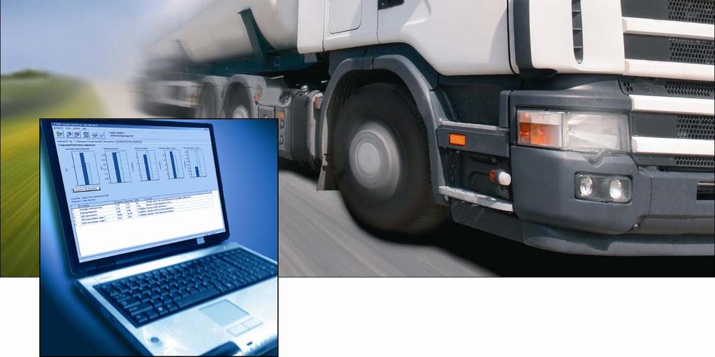
23 ODR Evaluation ODR-Tracker Long-/Short-term comparison A comparison of the long-term data (total lifespan of the ECU) is made with the short-term data (recording period of the trip recorder) under the tab Long-/Shortterm comparison. The following values are shown as tables and graphically: Average control pressure Braking frequency ABS interventions RSS interventions, stage 1 RSS interventions, stage 2 23
. Customers include the world s leading commercial truck, trailer, bus and passenger car manufacturers.")

24 WABCO Vehicle Control Systems, is one of the world's leading providers of electronic braking, stability, suspension and transmission control systems for heavy duty commercial vehicles. WABCO products are also increasingly used in luxury cars and sport utility vehicles (SUVs). Customers include the world s leading commercial truck, trailer, bus and passenger car manufacturers. Founded in the U.S. in 1869 as Westinghouse Air Brake Company, WABCO was acquired by American Standard in 1968 and spun off in Headquartered in Brussels, Belgium, the business today employs more than 7,000 people in 34 offices and production facilities worldwide. In 2006, total sales were $2 billion. WABCO is a publicly traded company and is listed on the New York Stock Exchange with the stock symbol WBC WABCO All rights reserved /
Universal Tristop Cylinder for Cam Brakes
 Tristop for Cam Brakes 3rd Edition This publication is not subject to any update service. New versions are available in INFORM at www.wabco-auto.com Copyright WABCO 2006 Vehicle Control Systems An American
DATA PD K Trailer Information Module (TIM G2) Product. Function. Technical Features. Options
 Product. Function. Technical Features. Options") Commercial Vehicle Systems Product DATA PD-273-920 Function The is a trailer mounted display for direct reading of diagnostic and trailer related information. It may also be used as a hand held diagnostic
Commercial Vehicle Systems Product DATA PD-273-920 Function The is a trailer mounted display for direct reading of diagnostic and trailer related information. It may also be used as a hand held diagnostic
Operating Instructions
 Operating Instructions for the WABCO Diagnostic Controller 446 300 320 0 with Program Card ECAS 4x2-A 446 300 521 0 or ECAS 6x2-A 446 300 527 0 or ECAS BUS-A 446 300 529 0 March 1996 Edition Copyright
TROVIS-VIEW 4 Software TROVIS Operating Instructions EB 6661 EN. Electronics from SAMSON
 TROVIS-VIEW 4 Software TROVIS 6661 Operating Instructions Electronics from SAMSON EB 6661 EN Edition January 2015 Definition of signal words DANGER! Hazardous situations which, if not avoided, will result
Type Operating Instructions - Software. Bedienungsanleitung - Software Manuel d utilisation - Logiciel
 Software of configuration Software der -Konfiguration Logiciel de configuration Operating Instructions - Software Bedienungsanleitung - Software Manuel d utilisation - Logiciel We reserve the right to
User's Guide. For CarChip and CarChip E/X 8210 & 8220
 User's Guide TM For CarChip and CarChip E/X 8210 & 8220 Product Number: 8210, 8220 Davis Instruments Part Number: 7395.064 DriveRight CarChip User s Manual Rev A (January 2, 2003) Davis Instruments Corp.,
CAN-Viewer (de) (en) of version 1.10 Operating Instructions
 (en) of version 1.10 Operating Instructions") CAN-Viewer 446 301 585 0 (de) 446 301 599 0 (en) of version 1.10 Operating Instructions 2nd Edition This publication is not subject to any update service. You will find the new version in INFORM under
CAN-Viewer 446 301 585 0 (de) 446 301 599 0 (en) of version 1.10 Operating Instructions 2nd Edition This publication is not subject to any update service. You will find the new version in INFORM under
DriveWizard Plus Instruction Manual
 DriveWizard Plus Instruction Manual To properly use the product, read this manual thoroughly. MANUAL NO. TOEP C730600 20C Table of Contents Safety Symbols and Markings...4 Manual Overview...5 Related Manuals...5
efesotomasyon.com - Lenze Manual Global Drive PC system bus adapter 2173 / 2177 Software installation & configuration
 L Manual Global Drive PC system bus adapter 2173 / 2177 Software installation & configuration CAUTION: The software is supplied to the user as described in this document. Any risks resulting from its quality
TROVIS-VIEW 4 Software TROVIS Operating Instructions EB 6661 EN. Electronics from SAMSON
 TROVIS-VIEW 4 Software TROVIS 6661 Operating Instructions Electronics from SAMSON EB 6661 EN Edition August 2017 Definition of signal words DANGER! Hazardous situations which, if not avoided, will result
EQP-104 OBD11 BLACK BOX RECORDER USER MANUAL
 EQP-104 OBD11 BLACK BOX RECORDER USER MANUAL 1 Table of Contents 1 1. Safety Information... 3 1.1 Conventions Used... 3 1.2 Important Safety Instructions... 3 2. Using This Manual... 4 3. Introduction...
Preface 1. X-Tools Client 2. Contact Information 3. User Manual X-Tools Client. English. Release English. Release / 25
 Preface 1 X-Tools Client 2 Contact Information 3 X-Tools User Manual - 02 - X-Tools Client Release 2015-11 Release 2015-11 1 / 25 Safety Guidelines This document contains notices which you should observe
SCD Live SPEED TECH A/S
 SPEED TECH A/S Nybrovej 97. DK2820 Gentofte. Phone: +45 45938545 Fax: +45 45938544 www.doorcontrol.dk - info@speed-tech.dk Contents: SCD Live 1 INTRODUCTION... 3 1.1 DESCRIPTION... 3 1.2 DISCLAIMER...
Mitchell International: (800)
") Table of Contents Getting Started with Mitchell Cloud Estimating 2 Access Mitchell Cloud Estimating 2 Configure Your Shop 2 Configure Your Shop or Company Information 2 View or Modify User Names and Contact
Table of Contents Getting Started with Mitchell Cloud Estimating 2 Access Mitchell Cloud Estimating 2 Configure Your Shop 2 Configure Your Shop or Company Information 2 View or Modify User Names and Contact
BNI USB A501. USB IO-Link Master User's Guide. english
 User's Guide english 1 2 4 Notes to the user 1.1 About this guide 1.2 Structure of the guide 1. Typographical conventions 1.4 Symbols 1.5 Abbreviations Safety 4 2.1 Intended use 4 2.2 General safety notes
Operating Instructions for the WABCO Diagnostic Controller with Program Card ECAS BUS - SAE
 WABCO Operating Instructions for the WABCO Diagnostic Controller with Program Card ECAS BUS - SAE 446 300 633 0 Operating Instructions for the WABCO Diagnostic Controller 446 300 320 0 with Program Card
QUICK START. DevCom2000 User Manual
 QUICK START DevCom2000 uses Device Descriptions (DDs) to access data stored in the memory of the smart field device. These DDs are developed by the manufacturer for their products and, in turn, distributed
EXPRESS. Users Guide. Version 3.5
 EXPRESS Users Guide Version 3.5 Table of Contents 1 System Overview... 3 2 System Requirements... 3 3 Contents in ECMTUNE System Box... 3 4 Installation Information... 4 5 Registration Information... 7
OBD Auto Doctor. User Manual for ios (iphone and ipad) Copyright 2018 Creosys Ltd
 Copyright 2018 Creosys Ltd") OBD Auto Doctor User Manual for ios (iphone and ipad) Copyright 2018 Creosys Ltd User Manual for ios (iphone and ipad) 1. Introduction 1.1 Platform and Hardware Requirements 1.2 Supported Adapters 1.3
OBD Auto Doctor User Manual for ios (iphone and ipad) Copyright 2018 Creosys Ltd User Manual for ios (iphone and ipad) 1. Introduction 1.1 Platform and Hardware Requirements 1.2 Supported Adapters 1.3
Preface 1. Main Management System 2. Contact Information 3 SIPLUS CMS. SIPLUS CMS4000 X-Tools - User Manual Main Management System.
 4000 X-Tools - User Manual - 03 - Main Management System Preface 1 Main Management System 2 Contact Information 3 4000 X-Tools User Manual - 03 - Main Management System Release 2011-09 Release 2011-09
InfoKey Programming Tool GUIDE aa
 InfoKey Programming Tool GUIDE 22081-00000aa Copyright 2008 Segway Inc. All rights reserved. Trademarks Segway Inc. ( Segway ) owns a number of trademarks including but not limited to, Segway and the Segway
Siemens Distributor SIMATIC. WinAC MP for MP370 V3.1. Preface, Contents. Product Overview. Transferring WinAC MP to the Multi Panel
 Preface, Contents SIMATIC WinAC MP for MP370 V3.1 User Manual Product Overview Transferring WinAC MP to the Multi Panel Developing and Downloading a STEP 7 Project for WinAC MP Controlling Your Process
INSTALLATION MANUAL. MEC-HL COMPACT Electromechanical proportional actuators for Hydraulic Applications
 INSTALLATION MANUAL MEC-HL COMPACT Electromechanical proportional actuators for Hydraulic Applications Table of Contents Legal Disclaimers, Copyright, Disclaimer, Safe system use, Customer Service Contact
Programming and Operating Manual Edition 10/2006. configuration software ASIMON for AS-Interface safety monitors. as-interface
 Programming and Operating Manual Edition 10/2006 configuration software ASIMON for s as-interface General Information 1 Installation of hardware and software 2 ASIMON First steps 3 Safety monitors Programming
Preface Master Data System Contact Information SIPLUS CMS
 Preface 1 Master Data System 2 Contact Information 3 X-Tools User Manual - 02 - Master Data System Release 2012-09 Release 2012-09 1 / 17 Safety Guidelines This document contains notices which you should
InControl INCONTROL OVERVIEW
 INCONTROL OVERVIEW InControl uses smartphone and in-vehicle mobile technology, to remotely connect the vehicle to a number of services and convenience features. Note: For further information, access the
FRC-F FRC-Q. PowerControl32 - Program description. Elektronik GmbH Tannenstrasse 11 D Oedheim
 FRC-F FRC-Q PowerControl32 - Program description 9.535.19/2 (valid for PowerControl32 from version 18.056.05) Page 1 of 19 C O N T E N T S 1 System requirements... 3 2 Installing the software... 3 3 Programs...
ISTA User instructions for the BMW Online Service System for BMW Service and MINI Service (OSS)
") ISTA User instructions for the BMW Online Service System for BMW Service and MINI Service (OSS) Release 1.0 Technical documentation and diagnosis BMW Group Page 2 Contents 1 Introduction......... 4 1.1
ISTA User instructions for the BMW Online Service System for BMW Service and MINI Service (OSS) Release 1.0 Technical documentation and diagnosis BMW Group Page 2 Contents 1 Introduction......... 4 1.1
TABLE OF CONTENTS TABLE DES MATIÈRES - ÍNDICE
 TABLE OF CONTENTS TABLE DES MATIÈRES - ÍNDICE ENGLISH Retrieve Codes... 1 View Results... 1 View Live Data... 1 Perform Additional Tests... 1 View Vehicle Information... 2 Access Reference Information...
Service Technical Resources MUT-III. (Multi-Use Tester-III*) Quick Reference Guide
 Quick Reference Guide") Service Technical Resources MUT-III (Multi-Use Tester-III*) Quick Reference Guide *Cart not included May, 2003 INTENDED USAGE OF MUT-III MUT-II role after MUT-III Launch MUT-III is an essential special
Service Technical Resources MUT-III (Multi-Use Tester-III*) Quick Reference Guide *Cart not included May, 2003 INTENDED USAGE OF MUT-III MUT-II role after MUT-III Launch MUT-III is an essential special
DIAGNOSTICS PN# / / FSP
 Diagnostic Monitoring These units are designed for data capturing simple measurements (pressure, temperature, and flow rate) in hydraulic and pneumatic systems. Typical applications extend primarily to
PROFESSIONAL. Users Guide. Version 3.5
 PROFESSIONAL Users Guide Version 3.5 Table of Contents 1 System Overview... 3 2 System Requirements... 3 3 Contents in ECMTUNE System Box... 3 4 Installation Information... 4 5 Registration Information...
Preface 1. Master Data System 2. Contact Information 3. User Manual Master Data System. English. Release English
 Preface 1 Master Data System 2 Contact Information 3 X-Tools User Manual - 02 - Master Data System Release 2014-11 Release 2014-11 1 / 21 Safety Guidelines This document contains notices which you should
Model 2000 Programmer EnSonic Display & Control Unit. Document code: M2KCNF.001
 Model 2000 Programmer EnSonic Display & Control Unit Document code: 10735.M2KCNF.001 Document Model 2000 Programmer: EnSonic Display & Control Unit Document code 10735.M2KCNF.001 Date January 25, 2004
Preface 1. Device Management System 2. Contact Information 3. User Manual Device Management System. English. Release
 X-Tools - User Manual - 04 - Device Management System Preface 1 Device Management System 2 Contact Information 3 X-Tools User Manual - 04 - Device Management System Release 2015-11 Release 2015-11 1 /
High Pressure E/P Regulator. ITVH Series
 Doc. No. DIQ-69200-OM002-A P R O D U C T N A M E High Pressure E/P Regulator MODEL/ Series/ Product Number ITVH Series Install and operate the product only after reading the Operation Manual carefully
Industrial Controls. Motor management and control devices SIMOCODE pro. Introduction 1. Configuring a reversing starter. List of abbreviations
 Introduction 1 Configuring a reversing starter 2 Industrial Controls A List of abbreviations Motor management and control devices Getting Started 05/2018 A5E40507294002A/RS-AB/002 Legal information Warning
CAMERA-MONITOR SYSTEMS
 CAMERA-MONITOR SYSTEMS FOR RECREATIONAL AND COMMERCIAL APPLICATIONS INSPIRED BY COMFORT 150546_reversing Brox2015V2_AM.indd 1 16/06/2015 3:42 pm 2 PERFECT VIEW SOLUTIONS READY-TO-INSTALL SYSTEMS FOR EVERY
Release Date: September 4, 2014
 MV1DU User s Guide Release Date: September 4, 2014 Use of the MV1DU Diagnostic System requires an active license agreement or MV-1 Dealer Agreement. For information on obtaining a license, please email
Instructions & Software Install Version 6.30a (Feb 2018) Copyright 2018 DealerTool.co.uk
 Copyright 2018 DealerTool.co.uk") DealerTool Instructions & Software Install Version 6.30a (Feb 2018) Copyright 2018 DealerTool.co.uk If you have any problems please email support@dealertool.co.uk Emails will always be responded to within
DealerTool Instructions & Software Install Version 6.30a (Feb 2018) Copyright 2018 DealerTool.co.uk If you have any problems please email support@dealertool.co.uk Emails will always be responded to within
Preface 1. Device Management System 2. Contact Information 3. User Manual Device Management System. English. Release
 X-Tools - User Manual - 04 - Device Management System Preface 1 Device Management System 2 Contact Information 3 X-Tools User Manual - 04 - Device Management System Release 2016-10 Release 2016-10 1 /
Preface 1. Storage System 2. Contact Information 3 SIPLUS CMS. SIPLUS CMS X-Tools - User Manual Storage System. English.
 X-Tools - User Manual - 07 - Storage System Preface 1 Storage System 2 Contact Information 3 X-Tools User Manual - 07 - Storage System Release 2012-09 Release 2012-09 1 / 44 X-Tools - User Manual - 07
INSTRUCTION MANUAL. IBREXDLL Software for MS Excel. M e t r o l o g y. Messtechnik GmbH & Co. KG
 M e t r o l o g y INSTRUCTION MANUAL Software for MS Excel Document No. : D2MF710 001 Edition : April 2009 Copyright : IBR Messtechnik GmbH & Co. KG Contents 1. Introduction... : 3 2. Features... : 3 3.
Connected to the FP World
 Connected to the FP World User Manual 2 mailcredit User Manual About this manual Target group Topics mailcredit.exe [Next] The User Manual of mailcredit is primarily aimed at users of FP franking machines
NAVIGATOR TX Range NEW
 NAVIGATOR TX Range NEW THE NAVIGATOR TX RANGE OF DIAGNOS The NAVIGATOR TX range of diagnostic and autodiagnostic interfaces is the result of constant research and the development of advanced solutions
Siemens Spares. Preface 1. Scope of Delivery 2 SIPLUS CMS4000. Product Characteristics 3 ION PROFIBUS DP SPY T001 Installation and Maintenance 4
 Preface 1 Scope of Delivery 2 Product Characteristics 3 Industrial I/O-Node ION PROFIBUS DP SPY T001 Installation and Maintenance 4 6AT8000-1BA00-5XA0 Notes on the CE Mark 5 References 6 Appendix 7 Release
System Monitoring SUNNY EXPLORER
 System Monitoring SUNNY EXPLORER User Manual ExplorerSW12-BEN104013 Version 1.3 EN SMA Solar Technology AG Table of Contents Table of Contents 1 Notes on this Manual.............................. 6 1.1
Configuration Manual KH EN. TROVIS Electric Actuator with Process Controller. for heating and cooling applications
 TROVIS 5757-7 Electric Actuator with Process Controller for heating and cooling applications Translation of original instructions Configuration Manual Firmware version 2.20 Edition September 2016 Notes
OBD GPS Tracker CW-601 User Manual
 OBD GPS Tracker CW-601 User Manual Tel: 0086-755-33633930 Fax: 0086-755-33633934 www.chainwayits.com Contents 1. PREVIEW... 2 2. DEVICE... 2 2.1 GENERAL INTRODUCTION... 2 2.2 TECHNOLOGY SPECIFICATIONS...
Device Type Manager DTM for TF12, TF212
 Manual 46/11-50 EN Device Type Manager DTM for TF12, TF212 PROFIBUS PA Communication for temperature transmitters TF12, TF212 P R O F I PROCESS FIELD BUS B U S Device Type Manager DTM for TF12, TF212 PROFIBUS
Two kinds of size notation are employed in this manual. With this machine refer to the metric version.
 Network Guide 1 2 3 4 5 6 7 Functions Available over a Network Connecting the Network Cable to the Network Setting Up the Machine on a Network Windows Configuration Using the Printer Function Configuring
Troubleshooter Quick Reference Guide
 Troubleshooter Quick Reference Guide March 2008 EAZ0025B29B Rev. C Trademarks Acknowledgement Snap-on, Scanner, and Fast-Track are trademarks of Snap-on Incorporated. All other marks are trademarks of
OPERATOR'S GUIDE. Innovative Vehicle Solutions
 OPERATOR'S GUIDE Innovative Vehicle Solutions Info Centre 2 Operator's Guide Notes on the use of this manual This manual has been designed to assist personnel in satisfactorily operating the Haldex Info
SMM501/501-H (Surveillance Mode Module) Ford Police Interceptors (Sedan and SUV)
 Ford Police Interceptors (Sedan and SUV)") An ISO 9001:2008 Registered Company SMM501/501-H (Surveillance Mode Module) 2013-2014 Ford Police Interceptors (Sedan and SUV) Introduction The SMM501/501-H is intended for 2013 and 2014 Ford Police Interceptors
An ISO 9001:2008 Registered Company SMM501/501-H (Surveillance Mode Module) 2013-2014 Ford Police Interceptors (Sedan and SUV) Introduction The SMM501/501-H is intended for 2013 and 2014 Ford Police Interceptors
Introduction to the Autologic Vehicle Diagnostic Tool
 Introduction to the Autologic Vehicle Diagnostic Tool User Instructions Version 4.0 Issued April 2012 For the latest version of this document see www.autologic.com Ltd has made every effort to make sure
Short instructions. Olympus FV1000
 Olympus FV1000-1- Short instructions Short instructions. Olympus FV1000 Version 140416 This short instruction will guide you through the turn on and off sequence of the microscope system. For a detailed
PHARO User Configuration Software UCS USER MANUAL Rev.0-15/07/ pharo.reer.it
 PHARO User Configuration Software UCS USER MANUAL 8540588 - Rev.0-15/07/2004 www.reer.it pharo.reer.it This document is protected by the law of copyright, whereby all rights established therein remain
Smart Mode Measurements
 Smart Mode Measurements Technical Reference for Maintenance PME 7.2.3 V1.0 Safety Information Important Information Read these instructions carefully before trying to install, configure, or operate this
1320 Electronics LLC USB-ALDL Cable User s Guide Electronics LLC. User s Guide for: USB-ALDL Cable
 1320 Electronics LLC User s Guide for: USB-ALDL Cable 1 Contents Warnings 3 Specifications 4 Configuration 5 Automatic Driver Installation 6 Manual Driver Installation 7 Driver Installation Verification
SCADAPack E ISaGRAF Quick Start Guide
 SCADAPack E ISaGRAF Quick Start Guide 2 SCADAPack E ISaGRAF Quick Start Guide Table of Contents Part I ISaGRAF 3 Quick Start Guide 3 1 Technical... Support 3 2 Safety... Information 4 3 Preface... 6 4
GV 2 Devicemanagement 2
 GV 2 Devicemanagement 2 getting started & usage 1/13 Index 1 General Remarks...3 2 Software...3 2.1 System Requirements...3 2.2 Installation...4 2.3 Un-Installation...5 3 User Interface...5 3.1 Menu Bar...6
Engineering Tool for PC SDWP001 Operating Manual
 Inverter HF-520/HF-X20 Series SF-520 Series Engineering Tool for PC SDWP001 Operating Manual 1 Manual No. DM2308E-1 Table of Contents Safety Symbols and Markings...4 Safety Notes and Instructions...4 Manual
PROCESS AUTOMATION MANUAL. Universal Transmitter Power Supply. KF**-CRG2-(Ex)1.D ISO9001
1.D ISO9001") PROCESS AUTOMATION MANUAL Universal Transmitter Power Supply KF**-CRG2-(Ex)1.D ISO9001 With regard to the supply of products, the current issue of the following document is applicable: The General Terms
PROCESS AUTOMATION MANUAL Universal Transmitter Power Supply KF**-CRG2-(Ex)1.D ISO9001 With regard to the supply of products, the current issue of the following document is applicable: The General Terms
Bendix & Eaton ABS Applications
 NEXIQ Brake-Link Bendix & Eaton ABS Applications Operator s Manual NEXIQ Brake-Link Bendix & Eaton ABS Applications Operator s Manual IDSC Holdings LLC retains all ownership rights to Bendix & Ea ton Applications
EasyDiag Series. User s Manual (V ) Issued Date:
 Issued Date:") EasyDiag Series User s Manual (V1.00.001) Issued Date: 2014-08-15 Note: This user s manual applies to EasyDiag Series (EasyDiag and EasyDiag Plus) and is subject to change without prior written notice.
EasyDiag Series User s Manual (V1.00.001) Issued Date: 2014-08-15 Note: This user s manual applies to EasyDiag Series (EasyDiag and EasyDiag Plus) and is subject to change without prior written notice.
Manual. Software Protection. TwinCAT 3. Version: Date:
 Manual Software Protection TwinCAT 3 Version: Date: 1.7 2018-10-25 Table of contents Table of contents 1 Foreword... 5 1.1 Notes on the documentation... 5 1.2 Safety instructions... 6 2 Introduction...
Hubio Fleet Management Platform User Guide
 Hubio Fleet Management Platform User Guide p2 Contents 1. 2. 3. 4. Login Menu Reports/Widgets 3.1 Track Report 3.2 Trace Report 3.3 Geofence 3.4 Speeding 3.5 GPS Distance 3.6 Activity Trace 3.7 Driver
VALCON EasyWriter Ver1.0E Manual
 VALCON EasyWriter Ver1.0E Manual E05172-K00022-00 Published Dec.2010 Ver3-1.03 HKS Co., Ltd. Revision History Revision Date 2008/12/10 First Edition (Ver3-1.01) 2010/4/2 Second Edition (Ver3-1.02) 2010/12/22
Options for collision shops to perform scan services independently
 Scan Tool and Services Overview for Pre-and Post-scanning Overview: Pre-and Post-scanning solutions available today for collision diagnostics vary widely for applications and capabilities. Some tools or
Software Manual R Index 1
 Software Manual R60727.0002 - Index 1 OS6.0 Operator software for Kübler devices Product features: For PCs and notebooks with Windows 7 or higher Easy parametrization, configuration and monitoring Additional
SIMPLE E-LOG APP USER MANUAL Page 1
 SIMPLE E-LOG APP USER MANUAL Page 1 CONTENTS-------------------------------------------------------- Revised on 10/31/2017 1. LOGIN CREDENTIALS... 3 1.1 Enter login credentials... 3 1.2 Forgot password...
Preface 1. Main Management System 2. Contact Information 3. User Manual Main Management System. English. Release
 Preface 1 Main Management System 2 Contact Information 3 X-Tools User Manual - 03 - Main Management System Release 2015-11 Release 2015-11 1 / 40 Safety Guidelines This document contains notices which
DEEP SEA ELECTRONICS
 COMPLEX SOLUTIONS MADE SIMPLE DEEP SEA ELECTRONICS DSE SCADA Suite Software Document Number 057-128 ISSUE 3 Author: Anthony Manton DEEP SEA ELECTRONICS PLC Highfield House Hunmanby North Yorkshire YO14
DATA PD-214-F107. TEBS G2 Doc. No. Y (EN - Rev. 003) September Product. Integrated Speed Switch (ISS) Function.
 September Product. Integrated Speed Switch (ISS) Function.") Commercial Vehicle Systems Product DATA Function The function provides a speed dependent output signal (electrical or pneumatic). TEBS G Doc. No. Y (EN - Rev. 00) September 0 Doc. No. Y (EN - Rev. 00)
Commercial Vehicle Systems Product DATA Function The function provides a speed dependent output signal (electrical or pneumatic). TEBS G Doc. No. Y (EN - Rev. 00) September 0 Doc. No. Y (EN - Rev. 00)
Component Tests User Manual
 Component Tests User Manual February 2009 EAZ0007E70C Rev. C Trademarks Acknowledgements Snap-on, Scanner, Fast-Track, and MODIS are trademarks of Snap-on Incorporated. All other marks are trademarks or
Data setting software MEXE02
 HM-40143 Data setting software MEXE02 OPERATING MANUAL Before Use Thank you for purchasing an Oriental Motor product. This operating manual describes product handling procedures and safety precautions.
SAFETY ADVICE (English)
") SAFETY ADVICE (English) Warning! It is critical that you read and follow this safety advice, the product description including technical data and the associated technical documentation, which are facilitated
SAFETY ADVICE (English) Warning! It is critical that you read and follow this safety advice, the product description including technical data and the associated technical documentation, which are facilitated
Modular CPU card and input / output card
 Modular CPU card and input / output card FEATURES» From the Vibro-Meter product line» One-Shot configuration of all VM600 cards using a direct Ethernet or RS-232 serial connection from an external computer,
User manual. PhysioPortWin. PC-Software for Ambulatory Blood Pressure Monitor (ABPM)
") User manual PC-Software for Ambulatory Blood Pressure Monitor (ABPM) PAR Medizintechnik GmbH & Co. KG Sachsendamm 6 10829 Berlin Germany 0482 Contents 1. GENERAL INFORMATION... 5 1.1 To this manual...
User manual PC-Software for Ambulatory Blood Pressure Monitor (ABPM) PAR Medizintechnik GmbH & Co. KG Sachsendamm 6 10829 Berlin Germany 0482 Contents 1. GENERAL INFORMATION... 5 1.1 To this manual...
User Manual. Open platform E Line. Part Number: Version: 1. Date:
 User Manual E Line Part Number: 80860.850 Version: 1 Date: 2014-01-27 Valid for: SB7ECS-OPENPLATL-0007 Version Date Modifications 1 2014-01-27 First edition This manual, including all illustrations contained
StruxureWare. Power Monitoring Expert 8.2 Hierarchy Manager Help Topics 7EN /2017
 StruxureWare Power Monitoring Expert 8.2 Hierarchy Manager Help Topics 7EN52-0413-00 03/2017 Legal Information The Schneider Electric brand and any registered trademarks of Schneider Electric Industries
Active Power Programmer Instructions
 Active Power Programmer Instructions Installation 1. Before you install the software, DO NOT PLUG the devices usb port into your computer. You will be ask to do this later in the installation 2. Run the
Temperature Transmitter head mounted TF02/TF02-Ex, field mounted TF202/TF202-Ex
 Release Note 34/11-51 EN Temperature Transmitter head mounted TF02/TF02-Ex, field mounted TF202/TF202-Ex FOUNDATION Fieldbus Firmware version 01.02.08 Hardware version 1.07 Temperature Transmitter head
PS-4700/4800Series User ユーザーマニュアル Hardware Manual Manual
 PS-4700/4800Series シリーズ User ユーザーマニュアル GP-4000 Pro-face Manual Series Remote HMI Server Hardware Manual Manual (Atom N270/Core 2 Duo 2 Duo P8400 P8400 Pre-installed 搭載モデル Model) ) Preface Thank you for
TDK Bluetooth for Windows Me
 Excellence in Collision Repair Car-O-Soft 2000 & Car-O-Soft Vision TDK Bluetooth for Windows Me Installation Guide (rev. 0) 2004-06 ENG Contents 1 Bluetooth for Windows Me for Car-O-Soft Vision... 2 1.1
TABLE OF CONTENTS. Safety Notices... 1
 TABLE OF CONTENTS Safety Notices... 1 System Overview... 3 Virtual Terminal (VT)... 3 Master Switch... 4 Working Set Master (WSMT) Module (Granular Fertilizer Control)... 4 Working Set Member (WSMB) Module
PROCESS AUTOMATION MANUAL. Temperature Trip Amplifier. KFD2-GU-(Ex)1 ISO9001
1 ISO9001") PROCESS AUTOMATION MANUAL Temperature Trip Amplifier KFD2-GU-(Ex)1 ISO9001 With regard to the supply of products, the current issue of the following document is applicable: The General Terms of Delivery
PROCESS AUTOMATION MANUAL Temperature Trip Amplifier KFD2-GU-(Ex)1 ISO9001 With regard to the supply of products, the current issue of the following document is applicable: The General Terms of Delivery
SEIKA. Trans Braille 40 Braille Display. User s Manual Version 3.36
 SEIKA Trans Braille 40 Braille Display User s Manual Version 3.36 Preface Thank you very much for purchasing a Trans Braille 40, Seika Braille Display. This Braille display enables pins to display characters
Electrical network protection Sepam series 20 Sepam series 40 Quick start
 03146790FE+01+NP00000000 Electrical network protection Sepam series 20 Sepam series 40 Quick start PE50465 Storage Sepam may be stored in its original packaging in a closed sheltered location: b ambient
ProAce ) After Sales implementation
 After Sales implementation") DiagBox on GTS ProAce ) After Sales implementation Diagnostic tool Repair Manual Electric Wiring Diagrams ProAce ) After Sales implementation What: For ProAce project TME has decided the adoption of PSA
DiagBox on GTS ProAce ) After Sales implementation Diagnostic tool Repair Manual Electric Wiring Diagrams ProAce ) After Sales implementation What: For ProAce project TME has decided the adoption of PSA
BNI PNT Z015. IP67 Modules 16 Input User s Guide
 BNI PNT-104-105-Z015 IP67 Modules 16 Input User s Guide Content 1 Notes 3 1.1. About this guide 3 1.2. Structure of the guide 3 1.3. Typographical Conventions 3 Enumerations 3 Actions 3 Syntax 3 Cross-references
DETROIT DIESEL MASTER REPROGRAMMING USER GUIDE
 DETROIT DIESEL MASTER REPROGRAMMING USER GUIDE DETROIT DIESEL ELECTRONIC CONTROLS (DDEC)... 2 HISTORY...2 OVERVIEW...3 DDEC REPROGRAMMING SYSTEM (DRS) SOFTWARE USAGE...4 IDS AND PASSWORD...5 WARRANTY INFORMATION...6
Satellic OBU Handbook
 Satellic OBU Handbook Date + version: December 2017 / OBU SW: 3.1 - status: Final - Created by: Marcom Approved by: Customer service Table of Contents Table of Contents... 2 List of Figures... 3 Abbreviated
PumpDrive DPM. Installation and Operating Instructions Dual Pump Module (DPM) /4--10
 /4--10") 4070.83/4--10 PumpDrive DPM Installation and Operating Instructions Dual Pump Module (DPM) These installation and operating instructions are not valid on their own. They must always be applied in conjunction
4070.83/4--10 PumpDrive DPM Installation and Operating Instructions Dual Pump Module (DPM) These installation and operating instructions are not valid on their own. They must always be applied in conjunction
ATMOS Capture Suite. Operating Instructions. English. These operating instructions are valid from software version 4.0. GA1GB
 Operating Instructions ATMOS Capture Suite English These operating instructions are valid from software version 4.0. GAGB.500.0 08- Index 0 Table of contents Introduction...4. Notes on operating instructions...4.
TST7600 Touch Screen with TMR Tracker OPERATORS MANUAL
 TST7600 Touch Screen with TMR Tracker OPERATORS MANUAL Ft. Atkinson, Wisconsin USA Panningen, The Netherlands www.digi-star.com D3989-EN Rev B 4 May 015 Table of Contents Table of Contents 1.0 INTRODUCTION...
Sigma DeviceNet Tool Change Systems USER S GUIDE Rev 05
 Sigma DeviceNet Tool Change Systems USER S GUIDE 94018 Rev 05 648 Saratoga Road Glenville, NY 12302 USA Phone: 518 384 1000 Fax 518 384 1200 www.arobotics.com 1. PRECAUTIONS 1 Sigma DNET Module 1 2.0 DNET
GAP Flasher. For all supported Vehicles. Quick Guide, Version 1.3 Firmware V1.0
 For all supported Vehicles By Quick Guide, Version 1.3 Firmware V1.0 1 1 Introduction This quick guide summarizes the operations needed to update the engine map and or firmware version. Some operations
SR200 GPS SPORTS WATCH. Keeping you one step ahead. User manual
 SR200 GPS SPORTS WATCH Keeping you one step ahead User manual Congratulations on purchasing your Snooper RUN SR200 Your new Snooper RUN SR200 is packed with loads of great features. It uses the latest
Lift Up Floor Locks Multi-Directional Castor. W Series. M Series (full stainless steel) WHEELS & CASTORS
 WHEELS & CASTORS") Lift Up Floor s Multi-Directional Castor K Series M Series O Series M Series (full stainless steel) W Series WHEELS & CASTORS WWW.SITECRAFT.COM.AU WHEELS & CASTORS Lift Up Floor s Used on warehouse trolleys,
Lift Up Floor s Multi-Directional Castor K Series M Series O Series M Series (full stainless steel) W Series WHEELS & CASTORS WWW.SITECRAFT.COM.AU WHEELS & CASTORS Lift Up Floor s Used on warehouse trolleys,