Jaguar IV Series User Manual
|
|
|
- Alberta O’Neal’
- 6 years ago
- Views:
Transcription


1 Jaguar IV Series User Manual V.2.4 Apr. 08
2 NOTICE GCC reserves the right to modify the information contained in this user manual at any time without prior notice; un-authorized modification, copying distribution or display is prohibited. All comments, queries or suggestions concerning this manual please consult with your local dealer. V.2.4 Apr. 08
3 Important Information Thank you for purchasing the GCC Jaguar IV Cutting Plotter. Before you use the cutting plotter, please make sure that you have read the safety precautions and instructions below.! Caution SAFETY PRECAUTIONS! For safety concern, please always hold the cutter firmly from the bottom while moving it. Do not move the cutter by clasping the depression area on both sides. O (Correct) X (Incorrect) Do not shake or drop the blade holder, a blade tip can fly out. During an operation, do not touch any of the moving parts of this machine (such as the carriage). Also be careful to make sure that clothing and hair do not get caught. Always connect the power cable to a grounded outlet. Always use the accessory power cable which is provided. Do not wire the power cable so that it becomes bent or caught between objects. Do not connect the power cable to branching outlet to which other machines are also connected, or use an extension cable. There is danger of overheating and of mis-operation of the machine. Keep the tools away from children where they can reach. Always put the pinch rollers within the white marks. Important Information
4 Warning Never press the top release grip and pull the bottom release grip at the same time as the pictures shown below: O (CORRECT) Press down (INCORRECT) Press down DISABLE Stop bar Pull up bottom to release grip ENABLE Note: In case the grips clipped together due to your wrong operation, please use a tweezers to pull out the stop bar when pressing down the top release grip. Keep the stop bar outside then release the grips as the right figure. Important Information
5 Important Information Table of Contents Jaguar IV User Manual 1. General Information 1.1 Introduction Package Items Product Features Appearance of Jaguar IV The Front View The Back View The Whole View The Left-hand Side The Right-hand Side Installation 2.1 Precaution Stand & Flexible Media Support System Desktop Flexible Media Support System Blade Installation Cable Connections USB Interface Parallel Interface RS-232 Interface Data Transmitting The Control Panel 3.1 The LCD Panel Menu in On-line Mode Menu in Off-line Mode Menu Items Operation 4.1 Media Loading Loading the Sheet Media Loading the Roll Media Tracking Performance Cutting Force and Offset Adjustment How to Cut 3mm Letter How to Make A Long Plot When Completing the Cutting Job Accu-Aligning System 5.1 Introduction Calibrating the System Media Calibration AAS Calibration AAS II on Jaguar IV Printer Test Contour Cutting Tips for AAS 5-8 Table of Contents
6 6. Maintenance 6.1 Cleaning the cutting Plotter Cleaning the Grid Drum Cleaning the Pinch Rollers Trouble Shooting 7.1 Non-Operational Problems Operational Problems Communication Problems Software Problems Cutting Quality Problem 7-5 Appendix A-1 Jaguar IV Specification A-1 A-2 Blade Specification A-2 A-3 CorelDRAW Plug-In Instruction A-3 A-4 SignPal 8.5 Instruction A-4 A-5 EasySIGN Instruction A-5 Table of Contents
7 1. General Information Jaguar IV User Manual 1.1 Introduction Jaguar IV series cutting plotters have been designed to produce computer-generated images or perform contour cutting on sheets or rolls of vinyl media. This manual covers the following models of Jaguar IV series cutting plotters: J4-61 J4-101S J4-132S J4-183S for media width: 50mm(1.97 ) ~ 770mm(30.3 ) for media width: 50mm(1.97 ) ~ 1270mm(50 ) for media width: 50mm(1.97 ) ~ 1594mm(62.7 ) for media width: 300mm(11.8 ) ~ 1900mm(74.8 ) 1.2 Package Items The package of the Jaguar IV model contents the items listed below, please check carefully. If you find any item missing, please consult your local dealer for further assistance. Standard Item Quantity 1. Cutting Plotter 1 2. Stand Set ( for J4-101S/132S/183S only )(Optional for J4-61) 1 piece of H-shape stand 2 pieces of stands 1 piece of stand beam 4 pieces of Hold Plugs 24 pieces of M6 screws 1 piece of M5 L-shape hexagon screw driver 4 piece of Stand Wheel 1 piece of Installation Guide for Stand Set 1 General Information 1-1
8 3. Flexible Media Support System Package Items 183S/132S/101S 61 1 set of Roll Media Flange (2 pieces) V V 1 set of Roll Holder (2 pieces) V V 1 set of Roll Holder Guide Bushes (4 pieces) V V 1 set of Roll Holder Support (2 pieces) V V 1 piece of M6 L-shape hexagon screw driver V V 1 piece of Installation Guide for Roll Holder V 1 piece of M5 L-shape hexagon screw driver V 1 set of Desktop Support Brackets (2 pieces) V 4 pieces of Plastic Foot V 4 pieces of M4 screws V 12 pieces of M6 screws V 1 piece of M4 L-shape hexagon screw driver V 1 4. Accessory Bag 1 piece of User s Compact Disk 1 piece of AC power Cord 1 piece of data cable (RS-232C) 1 piece of data cable (Print cable) 1 piece of data cable (USB cable) 1 set of Blade Holder Assembly (Installed in tool carriage of the cutting plotter) 1 piece of Blade (Installed in Blade Holder) 1 piece of Safe Blade 1 piece of Cutting Pad for Vinyl cutting 1 piece of Tweezers 1 piece of Promise Card Product Features The following are the main features of the Jaguar IV series cutting plotters: Tri-port connectivity provides you with greater flexibility. Up to 600-gram cutting force. Up to 60-inch/per second cutting speed. Guaranty 10-meter tracking. User friendly, multi-language control panel Ingenious media basket. Enhanced Accu-Aligning System for contour cutting. General Information 1-2
9 1.4 Appearance of Jaguar IV The Front View (Figure 1-1) Grid Drums move the media back and forth during operation. Tool Carriage performs the cutting with the installed blade and pen with AAS module. Control panel consists of 14 control keys and 1 LED and 1 LCM showing messages and menus. Slicer Groove slice off the extra media easily along this groove. Platen provides the surface for holding and supporting media while performing cutting. Alignment Rulers media can be aligned with the clear guide line marks. Cutting Pad provides the protection of blade when the blade is cutting. Figure The Back View (Figure 1-2) Lever raises or lowers the pinch rollers. Pinch Rollers hold the media during cutting. Figure 1-2 General Information 1-3

 Figure 1-4 Power Switch On when switches to [I]; Off to [O] Fuse 3 Amp.")
10 1.4.3 The Whole View (Figure 1-3) Roll Holder holds and supplies the roll media for cutting. Roll Holder Guide Bushes serve to keep the roll media in place when media is pulled from the roll. Stand Beam stabilizes the body. Roll Holder Support supports roll holders. H-shape Stand supports the cutting plotter body. Figure 1-3 Stand supports the cutting plotter body The Left-hand Side (Figure 1-4) Figure 1-4 Power Switch On when switches to [I]; Off to [O] Fuse 3 Amp. AC Power Connector used to insert the AC power cord. General Information 1-4
11 1.4.5 The Right-hand Side (Figure 1-5) Serial Interface Connector (RS232C) used to connect the cutting plotter to a computer through a serial interface cable. USB Connector used to connect the cutting plotter to a computer through a USB cable. Figure 1-5 Parallel Interface Connector used to connect the cutting plotter to a computer through a parallel interface cable. General Information 1-5
12 2. Installation 2.1 Precaution Please read below information carefully before you start installation. Notice 1 Make sure the power switch is off before installing the cutting plotter. Carefully handle the cutter to prevent any injuries. Notice 2 Choosing a proper place before setting up the cutting plotter Before installing your cutting plotter, select a suitable location, which meets the following conditions. The machine can be approached easily from any direction. Keep enough space for the machine, accessories and supplies. Keep the working area stable, avoiding sever vibration. Keep the temperature between 10 and 35 (50-95 o F) in the workshop. Keep the relative humidity between 25% and 75% in the workshop. Protecting the machine from dust and strong air current. Preventing the machine from direct sunlight or extremely bright lighting. Notice 3 Connecting the Power Supply Check the plug of the power cord to see if it matches with the wall outlet. If not, please contact your dealer. Insert the plug (male) into a grounded power outlet. Insert the other end (female) of power cord into the AC connector of cutting plotter. Installation 2-1
13 2.2 Stand & Flexible Media Support System (for J4-101S/132S/183S) Step 1 Please examine supplied items in the accessory box of stand carton: 1 piece of M6 L-shape hexagon screw driver 1 piece of M5 L-shape hexagon screw driver 24 pieces of M6 screws 4 pieces of hold plugs 4 piece of Stand Wheel 1 piece of Installation Guide for Stand Set Step 2 Remove the plotter body and the accessories from the shipped carton. Place the stands upright on the H-stand and follow the number to assemble. (See Figure 2-1 & 2-2) Stand beam Stand H-stand Figure 2-1 Figure 2-2 Step 3 Then, connect part and part. Insert 4 screws into the holes on H-stand and fasten them as shown in Figure 2-2. Installation 2-2
14 Step 4 Position the stand beam perpendicularly to part and put the screws into the holes and tighten them as Figure 2-3. Then the complete picture of stand will be like Figure 2-4. Stand Stand beam Screw H-stand Figure 2-3 Figure 2-4 Step 5 Remove the cutting plotter from the carton. Position your stand under the plotter, and then insert the screws into the holes on plotter s bottom and tighten them up as shown in Figure 2-5. Screws Figure screws holes Roll holder support 4 screws Figure 2-6 Step 6 Insert the roll holder support with the screws into the holes of the stand, then tighten them up Installation 2-3
15 as shown in Figure 2-6. You could decide roll holder support s position by inserting into different holes. Step 7 Place two roll holders into the holes in the roll holder support. (Figure 2-7) Roll holders Roll holder support Figure 2-7 Step 8 Lastly, the complete picture will be shown like below. (Figure 2-8) Figure 2-8 Installation 2-4
16 2.3 Desktop Flexible Media Support System (For J4-61 only) Jaguar IV User Manual Step 1 Please examine the following items in stand carton s accessory box: 1 set of Roll Media Flange (2 pieces) 1 set of Roll Holder (2 pieces) 1 set of Roll Holder Guide Bushes (4 pieces) 1 set of Roll Holder Support (2 pieces) 1 set of Desktop Support Bracket (2 pieces) 4 pieces of Plastic Foot 4 pieces of M4 screws 12 pieces of M6 screws 1 piece of M4 L-shape hexagon screw driver 1 piece of M5 L-shape hexagon screw driver 1 piece of M6 L-shape hexagon screw driver (for adjusting the screws of Roll Holders) 1 piece of Installation Guide for Roll Holder Step 2 Put the 4 Plastic Foot under the Roll Holder Support and insert the M4 screw into the hole of Plastic Foot and tighten them with the M4 L-shape screw driver. (Figure 2-9) Roll Holder Support Figure 2-10 M4 screw M4 screws Plastic Foot Figure 2-9 M6 screws M6 screws Desktop Support Brackets Roll Holder Support Step 3 Position the Desktop Support Brackets beside the Roll Holder Support and insert M6 screws into the Roll Holder Support and tighten them with M6 L-shape screw driver. (Refer to Figure 2-10 at the left). Installation 2-5
17 Step 4 Put the bottom of machine in lateral, and position the Roll Holder Assembly beside the bottom of the machine. Then, insert the M6 screws into the holes of Roll Holder support assembly and tighten them with M6 L-shape screwdriver. Like Figure Roll Holder Assembly Screw holes M6 screws Figure 2-11 Roll Holders Figure 2-12 Step 5 Place the two roll holders into the holes of Roll Holder Support (Figure 2-12). Step 6 The complete Desktop Media Support System will be shown as in Figure Figure 2-13 Installation 2-6

.")


18 2.4 Blade Installation Figure 2-14 is the illustrator of the blade holder. Insert a blade into the bottom of the blade holder and remove the blade by pushing the pin. Make sure that your fingers are away from the blade tip. Adjustment depth knob Pin Outward ring Figure 2-14 Step 1 Install blade (Figure 2-15). Figure 2-15 Figure 2-16 Step 2 Push the blade to the bottom of the blade holder. (Figure 2-16). Step 3 Adjust the blade tip to suitable length by screwing Blade tip adjustment screw clockwise or count-clockwise. (Figure 2-17). Tips: The proper length means the blade s length is adjusted 0.1mm more than film s thickness. That is, if the thickness of film is 0.5mm, then blade s length is properly adjusted 0.6mm and it can completely cut through the film layer yet avoid penetrating the backing. Figure 2-17 Installation 2-7


19 Step 4 Insert the blade holder into tool carriage. Please note the outward ring of the holder must put into the grooves of carriage firmly (see Figure 2-18), then fasten the case (Figure 2-19). Figure 2-18 Figure 2-19 Step 5 Use the reversing steps to remove the blade holder. Step 6 Eject the blade. Push Blade eject pin to eject blade when the blade needs to be replaced. Caution The blade will lose its sharpness after a period of usage, the cutting quality might be affected. By increasing the cutting force, it might do the trick. However, once the blade is worn out and no longer provides a reliable cutting, you should replace a new one. The blade is consumable and must be replaced as often as necessary to maintain the cutting quality. The quality of the blade deeply affects cutting quality. So be sure to use a high quality blade to ensure good cutting results. 2.5 Cable Connection The cutting plotter communicates with a computer through a USB (Universal Serial Bus), Parallel port (Centronics), or a Serial port (RS-232C). This chapter shows you how to connect the cutting plotter to a host computer and how to set up the computer/cutting plotter interconnection.!! Notice: When USB connection is enabled, both parallel port and serial port will be disabled automatically. Installation 2-8
20 Parallel port Serial port Figure 2-20 USB port USB Interface Jaguar IV build-in USB interface are based on the Universal Serial Bus Specifications Revision 1.1. (Operation system of Windows 95, Windows NT don t support USB). USB driver installation Caution!! Don t plug USB cable into plotter before you install USB driver. a. Put USB cable aside (don t plug it into Jaguar IV). b. Insert Installation CD, and then click on USB driver to install USB driver. When it Shows USB Driver installed.. Connection Plug the USB cable into the Jaguar IV USB interface connector. Plug the other end of the cable into the PC s USB interface connector. Cutting driver or sign cutting software installation Insert Installation CD, and then click on Driver to install driver working with CorelDraw Parallel Interface Connecting to the Parallel (Centronics) Port 1. Connect a parallel cable to the cutting plotter and the host computer. 2. Set up the output port LPT1 or LPT2 from your software package. 3. Send the data to your cutting plotter directly. Or, use DOS commands like TYPE or PRINT to output data. Caution!! Please turn off the plotter before plugging the print cable. Installation 2-9
21 2.5.3 RS-232 Interface Connecting to the RS-232 (Serial) Port 1. For IBM PC, PS/2 users or compatibles, connect the RS-232C cable to the serial connector of the assigned serial port (COM1 or COM2) of your host computer. 2. Set up the communication parameters (Baud Rate and Data Bits/Parity) to match the setting of software package, refer to chapter 3 Misc key description. Caution!! Please turn off the plotter before plugging the RS-232C cable Data Transmitting There are two options to transmit the data from the computer to the cutting plotter: Option 1: With proper interface settings, the data can be transmitted from your application software package to the cutting plotters directly. Option 2: Most cutting software packages are able to emulate HP-GL or HP-GL/2 commands, therefore, Use DOS commands like TYPE or PRINT to output your file. As long as the file is HP-GL or HP-GL/2 format, the cutting plotter can output the data precisely. For example, a file with PLT extension generated by SignPal Software can be transmitted directly to the plotter at the DOS prompt, and then be cut out. Before outputting at the DOS prompt, set up a transmission protocol between your cutting plotter and computer by a DOS command, MODE. Make sure that your PC has the same communication protocol as the cutter. For example: MODE COM2: 9600, N, 8, 1, P Then, use TYPE command to output via COM2 if COM2 is the assigned output port. TYPE filename > COM2 Tip: Add the MODE command line to your system s AUTOEXEC.BAT to automatically execute MODE command every time you want to output your data at the DOS prompt via serial connection. However, values in a MODE command should comply with the related requirements of your software. Refer to DOS manual for further information. Installation 2-10
22 3. The Control Panel This chapter describes the button operations with the LCM menu flowcharts of Jaguar IV. When the cutting plotter is ready for use as described in Chapter 1 & 2, all functions are under default parameters. 3.1 The LCD Panel POWER SPEED FORCE OFFSET MISC TOOL SELECT DATA CLEAR CUT TEST ON/OFF LINE PAUSE / RESUME ENTER < LCD Control Panel on Jaguar IV series > Key LCD Screen Function To display functions and error messages. Power LED To indicate the power status ( light up: power on; light off: power off ) 4 Arrow Keys To move position, select function, or change setting. ENTER PAUSE/RESUME ON/OFF LINE OFFSET FORCE SPEED CUT TEST DATA CLEAR TOOL SELECT To set item or register the immediately preceding input value. To temporarily halt cutting process or to continue To switch modes, stop cutting job, or abort changes of settings. To adjust the value of blade s offset. To adjust the value of cutting force. To adjust the value of cutting speed and quality. To perform cutting tests in different ways. To clear up buffer memory. To select tools. MISC To set up functions. Please see details in 3.4 Menu Items The Control Panel 3-1
23 3.2 Menu in On-line Mode Power On Jaguar IV in processing GCC Cutter LCM Version- - - Jaguar IV Firmware: Copyright: Place Media And Then Lower Down The Lever Roll Edge Single use to select Sizing Media Width Lever Up To Abort Sizing Media Length Lever Up To Abort Top menu S--- F----- O---- L W-----T1M Sending data [PAUSE ] Pause Setup Resume [ FORCE] Force:80 gf OK:ENTER [ SPEED ] use to select; [ENTER] to enable the setting Speed: 72 cm/s Select: OK:ENTER [ OFFSET ] Offset: mm OK:ENTER [ DATA CLEAR ] Clear Data Memory N:Cancel OK:ENTER [TOOL SELECT ] 1S:72 F:80 O:0.275 M Select: OK:ENTER Set Smoothing Cut Select: OK:ENTER UP Speed: Select: Quality: Select: 72 cm/s OK:ENTER normal OK:ENTER OverCut: 0.00mm Select: OK:ENTER Set Tangential Mode Select: OK:ENTER Pouncing Select: 0 mm OK:ENTER The Control Panel 3-2
24 3.3 Menu in Off-line Mode Press [ON/OFF LINE] to switch to the offline mode Offline For System Setup [ FORCE] Force:80 gf OK:ENTER [ OFFSET ] Offset: mm OK:ENTER 5~600 with an increment of 5(gram force) 0.000~1.000 with an increment of 0.025(mm) [ DATA CLEAR ] Clear Data Memory N:Cancel OK:ENTER [ ] move origin X: Y: [ SPEED ] Speed: 72 cm/s 使用 Select: 选择 OK:ENTER Speed:3~153 with an increment of 3(cm/s) UP Speed: 72 cm/s Select: OK:ENTER UP Speed:3~153 with an increment of 3(cm/s) [CUT TEST ] [TOOL SELECT ] [ MISC ] Firmware: x.x.xx FPGA:Vx.x Quality: Select: mm/dd/yy Auto Unrolled Media Select: OK:ENTER normal OK:ENTER Draft, Fair, Normal, Fine, Small Letter 1S:72 F:80 O:0.275 M Select: OK:ENTER Set Smoothing Cut Select: OK:ENTER OverCut: 0.00mm Select: OK:ENTER Set Tangential Mode Select: OK:ENTER Square Cut Select: OK:ENTER Repeat Last Plot Select: OK:ENTER Mark Positions Select: OK:ENTER OverCut: mm with an increment of 0.05mm Vacuum Select: OK:ENTER Media Back & Forth Select: OK:ENTER Pouncing Select: Panel Setup Select: 0 mm OK:ENTER OK:ENTER Pouncing:0-200mm with an increment of 1mm Paper Saving Mode Select: OK:ENTER Set Communication Select: OK:ENTER Select Language Select: OK:ENTER Restore default? Select: OK:ENTER Save parameter? Select: OK:ENTER Both Expanded Mode Length Expanded Mode Width Expanded Mode Both Unexpanded Mode Select Unit Select: Scale Length Select: Scale Width Select: AAS Offset Select: OK:ENTER OK:ENTER OK:ENTER OK:ENTER English,Chinese Metric (cm/gf) or English measurement (inch/oz) The Control Panel 3-3
25 3.4 Menu Items Below describes the functions of menu items Menu or Key Function Setting Default --- Media sizing --- Roll To measure media width. Maximum Tracking 150 meters Edge To measure media width and pull the media back till the front Maximum Tracking paper sensor open. 150 meters Single To measure media width and length. Maximum Tracking 10 meters --- POWER --- To indicate the power status. [ Arrow Keys ] 1. To move the tool carriage position on X or Y axis. 2. To select functions or change values of settings. [ ENTER ] 1. The displayed parameters will be saved automatically. 2. To set a new origin at the present tool carriage position. In offline mode, moving the tool carriage to desired position by [Arrow Keys], then press [ENTER] key to set a new origin. While moving with the parameters of XY-axes displayed, press [MISC] key will enable fine-tune movement; press [MISC] key again to disable the function. [ PAUSE/RESUME ] To temporarily halt the cutting process. To resume the process by press [Pause/Resume] key again. [ ONLINE/OFFLINE ] 1. To switch between online mode and offline mode. 2. To stop the cutting job or abort the change of setting. Once press this key, the cutting job will be terminated immediately and cannot be resumed. [ OFFSET ] To set or modify the distance between the blade tip and the center axis ~1.000mm 0.275mm [ FORCE ] To set or modify the value of tool force. 5~600gram; 5 gram/per step [ SPEED ] Speed To set or modify tool speed at horizontal moving. 3~153cm/sec; 3cm/sec per step 80 gram 72cm/sec Up Speed To set or modify tool speed at vertical moving. 3~153cm/sec; 3cm/sec per step Cutting Quality To set or modify cutting quality. Draft, Fair, While cutting small letter, set as Small letter. Normal, Fine, While cutting in high speed, set as Draft. Small Letter For normal operation, set as Normal. 72cm/sec Normal Square Cut [ CUT TEST ] To perform a cutting test at present blade position. For more information, please refer to 4.3 Adjusting the Cutting Force and Offset to adjust blade force and cutting speed. The Control Panel 3-4
26 Repeat Last Plot Recut: To repeat the last job without re-sending the data. Copy: To copy the last job without re-sending the data. * 1mm gap will be auto-generated between 2 copies). * If the media length is not enough to continue, it will show below message on LCM: Ou t O f S p a ce ; # o f C o p i e s f i n i s h e d * If both functions are enabled at the same time, the cutter will perform the last setting only. Jaguar IV User Manual 1~99; 1 per step 1~99; 1 per step Mark Positions Set Smoothing Cut 2-points: To manually position 2 points for contour cutting. 3-points: To manually position 3 points for contour cutting. To clear up buffer memory. [ DATA CLEAR ] [ TOOL SELECT ] To enable smooth-cutting function. Over Cut To generate an overcut to facilitate weeding. 0.00mm-1.00mm 0.05mm/per step Set Tangential To enable the emulated tangential-cutting mode for thicker Mode media types and small letter cuts. Note: while the Offset value setting at mm, Set Tangential Mode will automatically be disabled. Enable 0.00mm Enable Pouncing Panel Setup To make perforated patterns. 0~200mm * In order to use this function, Pouncing tool must be installed. * Before start pouncing, place pouncing strip on top of the cutting pad to protect the cutting pad. * Set the value as 0 mm to disable the pouncing mode. * Pouncing tool is an optional item. Accept setup command: To accept commands of the Force, Speed, Cutting Quality, and Offset only via software. Control panel only: To accept commands of the Force, Speed, Cutting Quality, and Offset only via control panel of the cutter. 0mm Restore Default To turn all parameters of the menu items to factory-default settings. Save Parameter Auto Unrolled Media To save pattern(s) of cutting parameters for later use. Patterns1~4 Pattern 1 [ MISC ] To avoid paper jam and motor crash by automatically unroll media (50cm and up) before cutting while enabled.. * Auto-unroll only effects on roll/edge media. * Using Single mode to size media will disable this function automatically. * If the length of the rolled media is less than 2 meters or the weight is light, it is recommended to set this mode disabled. Enable The Control Panel 3-5
27 Vacuum AAS Offset Media Back & Forth Paper Saving Mode To help improve tracking and cutting accuracy by turning on the fans. If you turn off the vacuum system, the fans will remain inactive during cutting or plotting. To set or modify AAS offset value. You can refer to 5.3 Printer Test for more details. To enable to save time on repeated cutting jobs and better tracking. After cutting job has finished, the media will move back to the origin, then move to the end of the plot. To save media by four different modes: 1. Length expanded mode 2. Width expanded mode 3. Both expanded mode 4. Both unexpanded mode Jaguar IV User Manual Enable Disable Both unexpanded mode Set Communication Firmware Version Select Language To build up the communication between host computer and cutter. Baud Rate is to determine the speed of data transmission. Data Bits refers to the size of one block of data. Parity is used to check if data was revived correctly or not. 9600, n, 7, 1, p 9600pbs, 7 Bits with NO Parity 9600, o, 7, 1, p 9600pbs, 7 Bits with ODD Parity 9600, e, 7, 1, p 9600pbs, 7 Bits with EVEN Parity 9600, n, 8, 1, p 9600pbs, 8 Bits with NO Parity 9600, o, 8, 1, p 9600pbs, 8 Bits with ODD Parity 9600, e, 8, 1, p 9600pbs, 8 Bits with EVEN Parity 19200, n, 7, 1, p 19200pbs, 7 Bits with NO Parity 19200, o, 7, 1, p 19200pbs, 7 Bits with ODD Parity 19200, e, 7, 1, p 19200pbs, 7 Bits with EVEN Parity 19200, n, 8, 1, p 19200pbs, 8 Bits with NO Parity 19200, o, 8, 1, p 19200pbs, 8 Bits with ODD Parity 19200, e, 8, 1, p 19200pbs, 8 Bits with EVEN Parity To display the version number of Firmware and FPGA code. To select displayed languages on LCM panel in English, Spanish, Italian, Deutsch, Japanese, Portuguese, Polish, Turkish or French. Select Units Provide two-unit systems for users convenient. cm/gram; inch/oz Scale Length To adjust the scale of media length and width that may cause by the thickness of the media. English Metric The Denominator is the actual length, and the Numerator is the ideal length measured from the resultant. Scale Width For example, cutting a line with mm length. The procedure as follows: 1. Press the [LEFT ARROW] to choose the Numerator and select mm, 2. Cut the length by sending a graph file, 3. Measure the length then use the [RIGHT ARROW] key to choose the Denominator, then 4. Press [UP ARROW /DOWN ARROW] to change the values of the actual length. The Control Panel 3-6
28 4. Operation 4.1 Media Loading Loading the Sheet Media To load the media properly, please follow the procedures listed below: Step 1 Use the lever on the upper right side of the cutting plotter to raise or lower down pinch rollers. Pull the lever forward until it makes a clicking sound then the pinch rollers are raised (Figure 4-1). Lever Figure 4-1 Step 2 Load your media on the platen and slide it under the pinch rollers from either the front side or the backside. The alignment rulers on the platen extension will help you to adjust the media precisely. Note: Be sure that the media must cover the paper sensors on the platen when loading the media. At least one of the two paper sensors (Figure 4-2) should be covered. Once the media covers the sensor, the cutting plotter will size the media width and length automatically. Paper sensors Figure 4-2 Operation 4-1
. White marks Figure 4-3 Step 4 Push the lever backward to lower down the pinch rollers.")
29 Step 3 Then move the pinch rollers manually to the proper position. Be sure the pinch rollers must be positioned above the grid drum. The white marks on the top trail will remind you where the grid drums are (Figure 4-3). White marks Figure 4-3 Step 4 Push the lever backward to lower down the pinch rollers. Step 5 Turn on the power, the tool carriage will measure the size of the media automatically. And the plotting cutter begins to work. Note: 1. Always adjust the position with the pinch roller raised. 2. Move the pinch roller by applying force at the rear portion of the pinch roller support. 3. Do not move it by holding its front rubber roller (Figure 4-4). (X) Incorrect Figure 4-4 Operation 4-2
 Insert the two roll holders into the roll media support set then place the roll media directly between the two roll holders (Figure 4-6).")
30 4.1.2 Loading the Roll Media Step 1 Put the roll media guide bushes on two roll holders (Figure 4-5). Figure 4-5 Step 2 -- Option A (Recommended) Insert the two roll holders into the roll media support set then place the roll media directly between the two roll holders (Figure 4-6). Figure Option B (Use the media flanges) Insert a roll media flange at the end of each roll media and tighten the thumbscrew until the roll media is firmly gripped(see Figure 4-7). Figure 4-7 Then put the roll media on the roll holders. Adjust the position of the roll media ensure that media flanges are able to run in the grooves of media guide bushes. (Figure 4-8) Figure 4-8 Operation 4-3
31 Step 3 Load the media on the platen. Please refer to Loading the sheet media. After loading the roll media, flatten the media on the platen and hold the front edge of the roll media firmly (Figure 4-9). Figure 4-9 Figure 4-10 Step 4 Turn the roll downward to make an equal tension across the media (Figure 4-10) Step 5 Move the pinch rollers to the appraise location and note that the pinch rollers must be positioned above the grid drums. Note : Make sure that the media tension is equally distributed from left to right. If the media were not tightened enough against the platen, it would cause tracking problems! Step 6 Push the lever backward to lower down the pinch rollers. Step 7 Fix roll media guide bushes on the roll holder to secure the roll media. Step 8 Turn on the power switch, the tool carriage will sizing the media automatically. Then the cutting plotter is ready to work. Step 9 Use the reverse steps to remove the media. Operation 4-4
32 4.2 Tracking Performance In order to achieve the best tracking performance for a long plot, we recommend some significant media loading procedures described as follows: If the media length is less than 4 meters, leave the margin of 0.5mm 25mm in the left and right edges of the media (Figure 4-11). 0.5mm - 25mm 0.5mm - 25mm Pinch roller Pinch roller Figure 4-11 If the media length is greater than 4 meters, leave at least 25mm margin on the left and right edges of the media (Figure 4-12). > or = 25mm Figure 4-12 > or = 25mm Please refer to the paragraph 4.5 How to Make A Long Plot for more details. Operation 4-5
33 4.3 Cutting Force and Offset Adjustment Before sending your designs for cutting, you may perform a cut test to generate satisfactory cutting results. The Cut Test should be repeated until the appropriate cutting conditions for the media are discovered. After sizing the media, press [CUT TEST] button to select the square cut, and press [ENTER KEY] to confirm. The default cutting force and offset value of the cutting test are 80gf and 0.275mm respectively. Press [ARROW KEY] to move the tool carriage to the position where you like. Then, press the [ENTER KEY] to perform Cut Test. Note: At the same time, the new origin is also set at the cutting test position. When the cutting test is completed, a pattern appears. Peel off the pattern to see if it can be easily separated from the media base. If yes, the setup tool force is appropriate. If not or cut through the back paper, press [FORCE KEY] to adjust the tool force until an optimum force is obtained (Figure 4-13). S q u a r e C u t S e l e c t : O K : E n t e r Press ENTER_KEY M o v e c u t t e s t X : Y : Press ENTER_KEY AA BB CC M If the pattern appears to be BB or CC layout, press [OFFSET KEY] to adjust the offset value until AA pattern discovered. C o n t i n o u s S q u a r e C u t N : O N / O F F LI NE O K : E n t e r Press ENTER_KEY Press SPEED_KEY, FORCE_KEY, OFFSET_KEY to setup or Press arrow keys to desired position for next square cut Finish square cut Press ENTER_KEY Press ON/OFF line_key 3mm 3mm Machine 80 mm 80 mm 80 mm Figure 4-13 Operation 4-6
34 4.4 How to Cut 3mm Letters To obtain good quality output, narrow media is recommended. However, if wide media is used, you should: 1. Position two pinch rollers as close as possible to both edges of the cutting area. 2. Make sure the loaded media is held flat with equal tension across the platen. 3. Suggested operation settings: Tool force: 55 gf. (or depending on the material) Cutting speed: cm/sec Tool up speed: cm/sec Smooth cut: Disable Quality: Small Letter 4.5 How to Make A Long Plot When you are making a long plot with a roll of heavy and wide vinyl, paper you need to use the AUTO UNROLL MEDIA function. The following parameter settings are to help users get the best cutting quality. The actual output quality may vary when using different kind of materials 1. If the length of graphic is between 3m and 5m, the cutting speed is better slower than 72cm/sec and the cutting quality is set as Normal. 2. If the length is longer than 5m or if the material type is difficult to cut, it is better to further slow down the cutting speed. 3. After loading the roll media all pinch rollers are raised at this stage, flatten the media on the platen and hold the front edge of the roll media firmly (Figure 4-14). Figure 4-14 Operation 4-7

35 Then turn the roll downward to make an equal tension across the media (See Figure 4-15) Make sure that the media tension is equally distributed from left to right. If the media is not tight enough against the platen, it will cause tracking problems. Figure Engage pinch rollers. 5. Fixes roll media guide bushes on the roll holder to secure the roll media. 6. The protrusion length of the blade should be longer than the thickness of the vinyl. (Please check the Blade Specification: About the Tool in Appendix.) After you notice all the above, you ll enjoy your gigantic signs production! 4.6 When Completing the Cutting Job After completing the cutting job, raise the sheet-loading lever, and then remove the material. You can also cut off the finished job by the Safe Blade (a standard accessory) along the knife guide. (Figure 4-16) Figure 4-16 Operation 4-8
 to guarantee precise contour cutting quality by detecting the registration marks printed around")
36 5. Accu-Aligning System 5.1 Introduction The Jaguar IV series cutting plotters feature a standard Accu-Aligning System (AAS II) to guarantee precise contour cutting quality by detecting the registration marks printed around the graphic. Notice Avoid any kind of light source horizontally illuminating the AAS module. - PROHIBITED - ACCEPTABLE DO NOT take off the cover of AAS module while in operation. - PROHIBITED 5.2 Calibrating the System The AAS system has one calibration procedures to ensure maximum accuracy of AAS operation. To operate the AAS you need to learn about the method of media feeding firstly. (4.1 Media Loading) Accu-Aligning System 5-1
37 5.2.1 Media Calibration Media Calibration is to ensure the sensor being able to recognize the registration marks. The factory default works on a wide range of materials. However, certain types of materials may not work properly. Performing a media calibration may become necessary while working with such materials to change the sensitivity of AAS for greater reliability. Media calibration adjusts the media feeding according to media type for better accuracy during cutting. When to use We suggest white media for best cutting result. It is not necessary to perform media calibration every time unless the registration marks on the printed media become undetectable in AAS sensing process AAS Calibration The first registration mark is designed to be different in order to identify the origin for AAS auto-detection. The following precaution must be aware for registration marks to be read automatically. Type of media Registration mark pattern Reading range required for detection the registration marks Position for registration marks and medium The registration marks have to be: Created by cutting software like SignPal or GCC CorelDRAW plug-in In black color L Mark Length: 10mm~50mm, suggested 25 mm L Mark Thickness: 1mm~2mm, suggested 1 mm Margin: 1mm~50mm, suggested 5 mm The cutter can not detect the marks while: Cutter carriage is not located near the outside area of first mark before detecting (See the picture in page 5-7 for auto-detecting area of first mark.) Medium thickness is more than 0.8mm Transparent medium is used Non-monochrome drawing. The marks can t be read if is printed on colored medium Dirty or creased medium surface Accu-Aligning System 5-2
38 5.2.3 AAS II on Jaguar IV There are three types of AAS II mark patterns: 4-Point Positioning, Segmental Positioning, and Multiple Copies. Note that before print out your designs by inkjet printers, the registration marks have to be created on your graphic designs by cutting software like SignPal, EasySign or GCC CorelDraw plug-in. Hand-made marks or drawings won t be reorganized by GCC cutting plotters. For more details about registration mark setting in cutting software, please refer to Appendix A-3 : CorelDraw Plug-In Instruction, Appendix A-4 : SignPal 8.5 Instruction and Appendix A-5 : EasySIGN Instruction Point Positioning This is the basic mark pattern that AAS II will auto detect four registration marks and contour cut images inside those marks. Command: Esc.D1;(XDist);(YDist): Layout: 4 L-shaped marks at the 4 corners around the design 2. Segmental Positioning In addition to 4 original points, the intermediate registration marks are added on both X axis and Y axis to help contour cut accurately, especially for cutting large images. Command: Esc.D2;(XDist);(YDist);(XStep);(YStep): Layout: In-between distance on X: 200~600mm, default 300mm In-between distance on Y: mm, default 300mm Accu-Aligning System 5-3
39 3. Multiple Copies The function is used to duplicate images to let you cut quantities of images at a time.the AAS II sensor will automatically scan registration marks for each individual image to ensure the contour cutting precision. Command: Esc.D3;(XCopies);(YCopies);(Space): Layout: Condition 1 (Default) Condition Printer Test Before performing AAS contour cutting, it s recommended to print out a test file that you can find in the enclosed Installation CD to make sure the AAS II cutting accuracy of Jaguar IV. There are two testing files for AASII: 1. AAS II_X_Y_Offset_Caberation_A4.eps (A4 size) 2. AAS II_X_Y_Offset_Caberation_600_600.eps (Default setting, it is recommended for testing) Print out the testing graphic. ( Please use high precision printer) Load the graphic to Jaguar IV and sent the file to test the cutting job If there is any adjustments had to be made, you can change the offset value by following the steps: * Measure the offset values from the printed line and the actual cutting line. Accu-Aligning System 5-4

40 * Enter the AAS Offset under MISC function for the values you just measured, then press Enter * Test the cutting again * AAS II offset X and Y value is defined as following: Horizontal line is defined as X and vertical is defined as Y * When the actual cutting line and the printed line need to be changed towards the direction of origin mark, then simply add the negative value of the offset. If the direction is from the opposite of the origin mark, then enter positive values for the offset. This method apply on both X and Y axle. For example: If the values set in cutter is X: 0.50 mm Y 0.50 mm and the measurement is X1:-0.25 mm Y 1:+0.25 mm. (In following figure, the Blue Line refers to the Y Value, and the Red Line refers toe the X value.) We need to adjust AASII offset X new : (X + X1) Y new : (Y + Y1) which means X new : 0.25 mm Y new : 0.75, then save the set new value to cutter. Note: Before adjusting the AAS II settings, please proceed scaling for width and length. Accu-Aligning System 5-5
41 The blade offset value isn t set for this test graphic, please set it according to the blade you use. If you have any question, please contact us or your local distributor for assistance. 5.4 Contour Cutting For accurate contour cutting with AAS function, please proceed the following steps: Step 1 Creating Graphics Create the graphic that you want to print and cut in your software. Create a contour line for cutting around the graphic. TIPS1: Leave some space between the graphic and contour line. TIPS2: Create the contour in a separate layer and assign a different color for it. Add registration marks around the graphic area in your software. Hand-made marks or drawings won t be reorganized by GCC cutting plotters. Note: The Multiple Copies function is also available. It automatically copies the graphic and registration marks. Accu-Aligning System 5-6

42 Step 2 Placing the Registration Marks The AAS Layout Instruction: * Auto-detection function on the 1 st mark covers the grey area Suggested 30mm margin on both left and right sides of media sheet. Suggested 20~30mm margin on top of media sheet, and at least 50mm margin on the bottom edge to prevent sheets dropping or any error occurred while media sizing. Step 3 Print the Graphics Print the graphic and the marks with your printer Accu-Aligning System 5-7


43 (Scaling = 100%). When printing on a roll media, make sure the orientation as following: Step 4 Load the printout onto cutter The Origin Mark is is different from the rest registration marks. Please make sure the media is fed with correct direction. Step 5 Cut the Contour Send out the command from software to perform the contour cutting job. 5.5 Tips for AAS For getting better results of contour cutting, there are some tips below for your reference. Keep light sources simple and avoid illuminating from the sides of cutter. Before operating AAS, change the maximum paper size in Jaguar IV driver property. STEP 1 Find the Jaguar IV model in the Printer & Fax folder of your PC. STEP 2 Open the Properties window and select the Paper tab. STEP 3 Change the maximum Paper Size of X to 1200mm. Adjust the cutting speed to between 300~600mm/sec. Avoid the registration marks locating on the tracks of pinch rollers. Accu-Aligning System 5-8
44 6. Maintenance This chapter explains the basic maintenance (i.e. cleaning the cutting plotter) required for the cutting plotter. Except for the procedures mentioned below, all other maintenance must be performed by a qualified service technician. 6.1 Cleaning the Cutting Plotter Cleaning the machine properly and regularly will ensure optimal performance out of your machine. Cleaning Precaution! Unplug the cutting plotter before cleaning it in order to prevent electrical shock. Never use solvents, abrasive cleaners or strong detergents for cleaning. They may damage the surface of the cutting plotter and the moving parts. Recommended Methods: Gently wipe the cutting plotter surface with a lint-free cloth. If necessary, with a damp cloth immersed in water or alcohol. Dry and wipe any remaining residue off a soft, lint-free cloth. Wipe all dust and dirt from the tool carriage rails. Use a vacuum cleaner to empty any accumulated dirt and media residue beneath the pinch roller housing. Clean the platen, paper sensors and pinch rollers with a damp cloth immersed in water or alcohol, and dry with a soft, lint-free cloth. Wipe dust and dirt from the stand. Basic Maintenance 6-1
45 6.2 Cleaning the Grid Drum 1. Turn off the cutting plotter, and move the tool carriage away from the area needed to be cleaned. 2. Raise the pinch rollers and move them away from the grid drum for cleaning. 3. Use a bristle brush (a toothbrush is acceptable) to remove dust from the drum surface. Rotate the drum manually while cleaning. Refer to Figure 6-1. Figure Cleaning the Pinch Rollers 1. If the pinch rollers require a thorough cleaning, use a lint-free cloth or cotton swab to wipe away the accumulated dust from the rubber portion of the pinch rollers. To prevent the pinch rollers from rotating while cleaning, use your finger to hold the pinch rollers to prevent them from rotation 2. To remove the deeply-embedded or persistent dust, use the lint-free cloth or cotton swab moistened with rubbing alcohol. Note: The daily maintenance of your cutting plotter is very important. Be sure to clean up the grid drum and pinch rollers regularly for better cutting accuracy and output quality. Basic Maintenance 6-2
46 7. Trouble Shooting This chapter is to help you correct some common problems you may come across. Prior to getting into the details of this chapter, please be sure that your application environment is compatible with the cutting plotter. Note: Before having your cutting plotter serviced, please make certain that the malfunction is in your cutting plotter, not the result of an interface problem or a malfunction in your computer or a software problem. Why is the cutting plotter not functioning? Possible Causes: 7.1 Non-Operational Problems Check the following first: Does the AC power cord plug in properly? Does the AC power cord connected to the power connector properly? Does the power LED still illuminate? Solutions: If the LCM is able to display the message, the cutting plotter should be in a normal condition. Switch off the cutting plotter and turn it on again to see if the problem still existing. If the LCM is not able to display any message, contact the technician from your dealer. Trouble Shooting 7-1
47 7.2 Operational Problems Some mechanical problems or failure during operation will cause some problems. The error messages shown on the LCM present the problem first, and followed by recommended actions. If the problem still exists after the recommended actions have been done, have your cutting plotter serviced. Error, Check Media Or Drum or X Motor This message indicates that there might be a problem on the X axis. Check if the drum is working well and if the media is well loaded. Correct the problem and re-power on to reboot system. Error, Check Media Or Y Motor This message indicates that there might be an obstruction to carriage relating to a problem on the Y axis. Correct the problem and re-power on to reboot system. Error, Check Carriage Sensor or VC Motor This message indicates that the blade up/down sensor malfunction. Re-power on to re-boot system. If the problem still exists, find a serviceman. Graph Was Clipped. Data In Buffer This message indicates that the cutting exceeds the cutting limit. Reload larger media or re-scale the plot to a smaller size; then press the key followed by the display of LCM to continue. Trouble Shooting 7-2
48 7.3 Cutting Plotter/Computer Communication Problems The messages showed below present problems in relation to cutting plotter/computer communication. Communication Error Setup: MISC. key Is the connection cable connected to the cutting plotter and computer properly? Yes No Has the interface setting been done correctly? Yes No Refer to Chapter 2 - Connecting your cutting plotter. Try the communication between your cutting plotter and computer. If it still does not work, have your cutting plotter serviced. Refer to the MISC key in Chapter 3 - Description of Operation for the port setup. Note: The computer also needs to set up compatible communication parameters to the cutting plotter set up. HP-GL/2 Cmd. Error If your cutting plotter can not recognize the HP-GL/2 or HP-GL commands, please check the HP-GL/2 or HP-GL commands applied to your cutting plotter are used properly. Trouble Shooting 7-3
49 7.4 Software Problems Check the following first: Does your software package indicate that it will work with your computer and cutting plotter? Does your software support HP-GL and HP-GL/2 drivers? (* check the configuration settings of your software.) Yes No Does the cutting plotter interface match the requirements of your software? Yes No Does your Refer to Chapter software 2 - Connecting recommend your cutting using a different plotter. cable? Most well known cutting softwares in the world have drivers for our cutting plotters. If not, use software that has HP-GL and HP-GL/2 emulation supports and you can chose the following three drivers: A3 size: HP7475A A1 size: HP7580A A0 size: HP Draf Pro Exl or HP Draf Master Yes Try using the recommende d cable. No Does the software vendor provide a sample file? Yes No Re-power on the cutting plotter and try to send the file again. Do something about the error message display on LCM, or consult your software vendor. Trouble Shooting 7-4
50 7.5 Cutting Quality Problems Note: The daily maintenance of your cutting plotter is very important. Be sure to clean up the grid drum and pinch rollers regularly for better cutting accuracy and output quality. Is the blade installed correctly and the blade holder fastened securely? Yes No Is the blade dull or chipped? Refer to Chapter 2.4 Blade Installation Yes No Replace with a new blade Is tool force set up properly? (The default for tool force is 80 gf) Yes No Is the tool offset set up properly? Yes No Adjust the tool force to obtain an optimum blade force. Refer to Chapter 4.3 Cutting Force and Offset Adjustment Is there any dirt adhered to the blade? Adjust the tool offset to obtain an optimum value. Yes No Remove the blade and clean it. Please contact your dealer for technician support. Trouble Shooting 7-5
51 Jaguar IV Specification Model Number J4-61 J4-101S J4-132S J4-183S Operational Method Roller-Type Max. Cutting Width 610mm (24in) 1016mm (40in) 1320mm (52in) 1830mm(72in) Max. Cutting Length 50m (164ft) Max. Media Loading Width 770mm (30.3in) 1270mm(50in) 1594mm(62.7in) 1900mm(74.8in) Min. Media Loading Width 50mm (1.97in) 300mm (11.8in) Number of Pinch Rollers Acceptable Material Thickness 0.8mm (0.03in) Drive Motor DC Servo Control Cutting Force 0~600 g Max. Cutting Speed 1530 mm/sec (60ips / Diagonal) Acceleration 4.2 G (gravity) Offset 0~1.0 mm (with an increase of 0.025mm) Memory Buffer 4 MB Interfaces USB1.1, Parallel and Serial (RS-232C) Type of Command HP-GL, HP-GL/2 Mechanical Resolution mm Software Resolution mm Repeatability ±0.1mm Curve & Arc Smoothing Yes Configurable Origin Yes Test Cut capability Yes Tangential- emulation Yes Repeat Yes Copy Yes Pouncing Yes Control Panel LCD (20 digits x 2 lines), 14 Keys, 1 Power LED Power Supply AC V, 50~60 Hz (auto switching) Power Consumption Max. 110watts Dimension (HxWxD) mm 414 * 930 * * 1430 * * 1754 * * 2170 * 1160 (HxWxD) in 16.3 * 36.6 * * 56.0 * * 69.1 * * 85.4 * 45.7 Net Weight 37.2 kg 53.3 kg 61 kg 105 kg Stand Optional Standard Accu-Aligning System Standard AAS-II Media Basket Optional Operation Temperature 10 C~35 C / 50 F~95 F Environment Humidity 25% ~ 75% The specification and data sheet may vary with different materials used. In order to obtain the best output quality, please maintain the machine regularly and properly. GCC reserves the right to change the specifications at any time without notice. Jaguar IV Specification A-1
52 Blade Specification G For cutting thick fluorescent and reflective vinyl. Also for cutting detailed work in standard vinyl. The blade is 45 with Red Cap, 0.25 mm offset G For cutting reflective vinyl, cardboard, sandblast, flock, and stencil sharp edge. The blade is 60 with Green Cap, 0.50 mm blade offset G For cutting thin sandblast mask and stencil with friction feed or sprocket feed machine. The blade is 60 with Blue Cap, 0.25 mm blade offset G For Cutting small text and fine detail. Sharp blade with smallest offset. The blade is mm blade offset with Black Cap Blade Specification A-2
53 About the Tool A generic term referring to the blade that cuts the sheet, the pen that does plotting, and the LED bombsight (option) used for pointing to the reference point. OFFSET is the distance that the blade tip is displaced from the centerline of the blade. Blade Blade tip Central line offset Protrusion Length of the Blade Protrusion length of the blade Thickness of the media (t1) Thickness of the base paper (t 2) Length of protrusion = t1 + t 2/ 2, but for your convenience you may just make it about 0.3mm ~ 0.5mm beyond the blade holder tip. Blade Specification A-2


54 CorelDRAW Plug-In Instruction AASII VAB Installer is applicable for CorelDRAW Version 11,12,13 Installation 1. Check the AAS CorelDraw Installer folder in Jaguar IV Installation CD, and double click the AASIIVBAInstaller.exe file to run the installation program. 2. Press Install button and start to install GCC AASII CorelDRAW VBA. CorelDRAW Plug-In A-3

55 User Instructions 1. Open CorelDRAW, finish editing all the files you wish to plot and select all the image at once. 2. Select Tools Visual Basic Play. The Visual Basic for Applications Marcos window will pop up. CorelDRAW Plug-In A-3


56 Select GCC_CorelDraw_AASII (GCCAASII_Draw12.gms) under the Micros in manual, and press Run. 3. Click on Apply. 4-Point Positioning Length: The length of marks Range: 10mm~50mm Optimized Setting: 25mm Thickness: The line thickness of marks Range: 1mm~2mm Optimized Setting: 1mm Margin: The distance between marks and images Range: 1mm~50mm Optimized Setting: 5mm Segmental Positioning X Step: The distance of intermediate position on the X axis Y Step: The distance of intermediate position on the Y axis Range: 200mm~600mm Optimized Setting: Less than 500mm Multiple Copies No. of X Copies: The numbers of copies on X axis No. of Y Copies: The numbers of copies on Y axis Range: 1~50. (The more copies you make, the more time is needed for data transmission.) Numbers of X Copies * Numbers of Y Copies = The total amount of image copies Copies with outline:to show outlines of image graphics CorelDRAW Plug-In A-3


57 The system will create the necessary 4 marks on the picture. 4. Now you can output the image file directly to Jaguar IV to run the AAS function. You can also pull out a Hot Icon for the AAS II Plug-in Step 1: Select Tools Customization Commands Macros. Step 2: Choose GCC_CorelDraw_AASII.GCCModule.GCC_AASII and drag it to commands bar. CorelDRAW Plug-In A-3

58 Step 3: If you want to have a different icon, select Tools Customization Commands Appearance to import the graphics. Choose an icon and press OK to finish this setting. CorelDRAW Plug-In A-3
59 SignPal 8.5 Instruction The new SignPal 8.5 Software is Windows Vista compatible and the SignPal Expert above versions support the AAS II contour cutting function of Jaguar IV and Puma III cutting plotters. Different to the previous SignPal 7.6 version, the SignPal 8.5 doesn t come with a keypro dongle, which is replaced by a softkey to simplify the installation procedure. However, please note that the system must be connected to the Internet when launching the SignPal 8.5 software for the first time with softkey. Internet access is required for online validation during the initial installation and for future online validations every 30 days. If the softkey is unable to connect to the Internet within a 30 day period, you will receive a message alerting you that you can only continue working with the software for another 10 days without connecting to the Internet. For users without Internet or broadband connection, please contact your local distributor to purchase hard keys (keypro dongle) and provide them your softkey ID & password for replacement. Your original softkey ID & password will be invalid after replacement, and the new hard key ID & password can work only with the dongle inserted to your computer. Please note that the softkey and hard key has different user ID number as following: Soft key IDs are 9xxxxx Hard key IDs are 5xxxxx SignPal 8.5 Instruction Index: [1] Installing the SignPal 8.5 software.. P.01 [2] Set up your GCC Cutter on Production Manager. P SignPal AAS II Quick Start P.13 [3] Transferring a Software License Using Softkey P.18 [4] SignPal 8.5 Feature Lists.. P.20 [1] Installing the SignPal 8.5 software To install the software, you must have Administrator privileges. To use the software, you must have Administrator or Power User privileges. See your Windows user guide for more information. 1. Uninstall any previous version of the software. 2. Insert the Installation DVD. 3. Select a language and click OK. SignPal 8.5 Instruction A-4 1


60 4. Click Next. 5. Read the Software License Agreement and select I accept the terms of the license agreement and click Next to accept. SignPal 8.5 Instruction A-4 2

61 6. If you did not have any previous versions of the software installed, skip to the next step. If you still have a previous version of the software installed, you will be prompted to overwrite the existing installation. Click Yes to overwrite any previous installation of the software. 7. Select the features of the software that you want to install and click Next: Check GCC Production Suite to install the software. Check Samples to install sample files. Check SafeNet Sentinel System Driver to install the software driver for this key. If you do not use this type of key, you do not need to install this driver. A. To change the default destination folder, click Browse and choose a new destination folder. B. To check that the drive you are installing to has enough space for the installation: a. Click Disk Space. SignPal 8.5 Instruction A-4 3


62 b. From the drop-down menu, select the drive you want to install to, and verify that it has enough space for the installation. c. Click OK. The installation drive changes to the selected drive when you click OK. 8. Select the Program folder where the shortcut for the software will appear. A new folder is automatically created for the product. 9. Click Next to install the software. SignPal 8.5 Instruction A-4 4

63 10. Once the installer is finished installing, the Install Manager opens. The Install Manager allows you to run a demo version of any available products, or to enter a password to access the software and any optional features. 11. Do one of the following: Check Run in demo mode to run a demo version of any available products in any available language. Enter a Password, and then select a product from the Product list and a language from the Language list. Use the Add button to enter any additional passwords in the Optional Password section to unlock optional features. Password This is your main application password for the software. Optional Password If you purchased additional options, you may enter the option passwords in this field to upgrade your software. 12. Click Done. SignPal 8.5 Instruction A-4 5


64 13. Check which icons and preferences you want to install: Check Install to desktop to install a shortcut for the software on the desktop. Check Install to startup items to install a shortcut for the software in the Startup folder of the Start menu. If this is done, each time the computer starts up, the software will automatically start up and minimize itself, displaying an icon in the system tray of the Windows system tray. Check Clear Application's previous preferences to clear the preferences or clear the check box to retain old preferences. Click OK. SignPal 8.5 Instruction A-4 6

65 14. Open SignPal 8.5v1 15. As you have not registered before, please check on the box at bottom to register a new account. 16. Input your personal information to complete the online registration. SignPal 8.5 Instruction A-4 7

66 17. If you have registered before, please enter your Registration code as below to open SignPal 8.5v1 software. SignPal 8.5 Instruction A-4 8


67 SignPal 8.5 Instruction A-4 9
![[2] Set up your GCC Cutter on Production Manager 1.](/docs-images/71/66122408/images/68-0.jpg "Open Production Manager 8.5v1 2.")

68 [2] Set up your GCC Cutter on Production Manager 1. Open Production Manager 8.5v1 2. Choose and set up your GCC cutter. (Note that AAS II System only works on Jaguar IV and Puma III.) SignPal 8.5 Instruction A-4 10


69 3. Select File > Print Setup in SignPal Software. SignPal 8.5 Instruction A-4 11

70 4. Select the printer and paper size. SignPal 8.5 Instruction A-4 12
71 -- SignPal AASII Quick Start 5. Use the Rectangle Tool to create a rectangle. 6. Select Effect > Contour Cut. Then click Apply in DesignCentral window. SignPal 8.5 Instruction A-4 13

72 7. Apply the contour cut mark of GCC AASII by selecting Effect > Contour Cut Mark. 8. Select GCC AASII in SignPal DesignCentral window to create the AAS II registration marks (4-Point Positioning). Set the vales as 0.1cm or above and click Apply in DesignCentral window. The value is to define the distance between registration marks and image area. If the value is less than 0.1cm, it is likely that the image will overlap the marks and result in bad cutting quality. 9. There are three types of GCC AASII registration marks: 4-Point Positioning, Segmental Positioning, and Multiple Copies. To make Segmental Positioning marks, please select GCC SignPal 8.5 Instruction A-4 14


73 Segmentation in DesignCentral window and then click Apply. 10. For Multiple Copies, this function is not available in SignPal. Currently the Multiple Copies function is only available under CorelDRAW plug-in. 11. Select File > Print to print out the image. SignPal 8.5 Instruction A-4 15

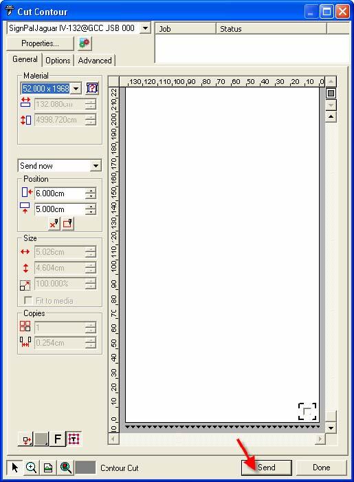
74 12. Set the Scale as 100cm =1m (100%) in Print page. 13. Load the printout vinyl on the plotter and select File > Cut Contour to send data. You can preview the job and change cutter s parameter settings in Properties tab of Cut Contour window. The Production Manager will be automatic activated to complete the job. SignPal 8.5 Instruction A-4 16

75 SignPal 8.5 Instruction A-4 17
![[3] Transferring a Software License Using Softkey Softkey allows you to transfer the software license to another computer by disabling the software](/docs-images/71/66122408/images/76-0.jpg "license on one computer, and enabling it on another.")


76 [3] Transferring a Software License Using Softkey Softkey allows you to transfer the software license to another computer by disabling the software license on one computer, and enabling it on another. Remarks: If you would like to upgrade or reinstall the Windows OS, please transfer your license before reinstallation. If your hard drive has been formatted and you forget to transfer license in advance, please provide your SignPal ID and password to your local distributor, they will contact GCC to reset your data, and you will be able to register again afterward. 1. From the Help menu, mouse over Registration and select Transfer License. 2. Click Yes to deactivate the software license on the computer currently running the software. You can reactivate the license on another computer or the same computer. 3. Make note of your Registration ID and click OK. SignPal 8.5 Instruction A-4 18


77 4. Install the software on the computer you wish to transfer the license to. SignPal 8.5 Instruction A-4 19
78 [4] SignPal 8.5 Feature Lists Working with Files Pro Master Expert Apprentice Job Info Templates Using DesignEditor DesignEditor Arranging Objects Distribute Working with Color Eyedropper Using Fill/Stroke Editor Overprint Working with Shapes Fan Arrow Working with Text Text Block Size URW Font Support Optional Working with Bitmaps Scanning Rasterize Colormode Marquee Move Eraser Pencil Fill Crop AutoTrace ColorTrace Working with Effects Color Trapping Graphic Styles Contour Working with Measurements and Labels Dimensions / Labels Automatic Dimension Dimension to Page Cutting your Design Cut/Plot SignPal 8.5 Instruction A-4 20


79 EasySIGN Instruction The user manual of EasySIGN software is available on the EasySIGN program CD, or you can refer to the getting started manual available on the EasySIGN webpage at GCC AASII Corpmark System This application note will show you how to use the GCC AASII corpmark system. It assumes that you have installed your GCC plotter correctly, and that you are able to cut simple jobs on it. If not, please refer to the Getting started manual available through the menu "Help, Various, GettingStarted.pdf". 1. Make or import a design You can either make the design in EasySIGN or import an existing design from another application. For making the design in EasySIGN refer to the "Getting Started" manual. To import a design (for example an Adobe illustrator file) into EasySIGN, use either the compatibility option, or use direct import (menu : "File, Import"). The easiest way is to use compatibility. To do this, start EasySIGN, then use the menu File, Compatibility, and click the software of your choice. This software will now start, and can be used to design or open the required job. Click the icon in the system tray to easily send the file into EasySIGN. 2. Create print & cut lines. When your design is successfully imported into EasySIGN, you should then select the line or lines that you want to cut on your plotter. After selecting them, use the command Edit, Convert to, Line type, Print&cut line. The lines that will be cut are now shown in a dotted red line. Copy the design as you like. EasySIGN Instruction A-5


80 3. Enable the cropmarks. Right-click on an empty part of the worksheet, and choose the command Cropmark settings. This will show a dialog. Please tick the box called Show Print & cut cropmarks. Next, you need to make a choice which system that you want to use, there are three different systems: GCC AASII This system uses four cropmarks, and one copy. It is meant for jobs that are not very large (like 60 cm or smaller) and that are going to be printed on single sheets. GCC AASII, Multicopy Use this system when you want to cut multiple copies of a small job. This will give you very high accuracy, but the plotter will scan every copy of the job separately, which is of course slower than one big job. GCC AASII, Multisegment Use this system when the job is large. We recommend it for jobs bigger than 60 centimeter. It will place extra markers on the sheet, which will enhance the accuracy but will take extra time to scan. The size of the cropmarks is fixed at 25 mm. Just click OK to close the dialog. If you have chosen the Multicopy cropmarks, there will be extra settings for horizontal copies, vertical copies etc, please ignore these for now, we will get back to them later. EasySIGN Instruction A-5

 as the output format, this can be read by any RIP or other print software. Print the resulting EPS file with the software of your choice. 6.")
81 4. Position the cropmark Use the panelling tool from the left toolbox to drag the cropmarks around your job. Make sure that the cropmarks have some white space around them, there should not be any objects inside them, to make sure they can be scanned accurately. 5. Export the job for printing Your design is now ready for production. Click File, Export, and a dialog will come up that enables you to create a file. We advise you to use EPS Encapsulated Postscript (*.EPS) as the output format, this can be read by any RIP or other print software. Print the resulting EPS file with the software of your choice. 6. Cut the result Place the resulting print in your plotter. Set the plotter to offline and use the arrow keys to position the laser within the lower right cropmark, then set the plotter to online. If you have chosen the cropmarks Multicopy, there is one extra step: right-click the page and go to the Cropmark settings dialog again. In the dialog, enter the correct values for nr. Of copies horizontal, Nr of copies vertical and Copy distance horizontal, copy distance vertical, then click OK. EasySIGN Instruction A-5
 Switched on Normal line (2) Switched off Print and cut line (3) Switched on Then click OK.")
82 In the EasySIGN software, choose File, Plotting. A dialog will come up that allows you to change the plotter settings. Just make sure that the following settings are made: Alignment plotting (1) Switched on Normal line (2) Switched off Print and cut line (3) Switched on Then click OK. Your plotter will then start scanning the cropmarks, and after that the job will be cut. EasySIGN Instruction A-5
USER MANUAL. Sign Cutting Plotter VC-600 VC-1300 VC Read This Manual Before Using The Plotter.
 USER MANUAL Sign Cutting Plotter VC-600 VC-1300 VC-1800 Read This Manual Before Using The Plotter. Rev No. Trademark Mentioned in this Manual MUTOH, ValueCut, VC-600, VC-1300, VC-1800, ValueJet are registered
LYNX. SIGNWarehouse com. User's Guide. lynx_man_rev1_0504
 LYNX User's Guide SIGNWarehouse com lynx_man_rev1_0504 Table of Contents 1. Learning 1.1 Initial Inspection 1-1 1.2 Front View of Lynx 1-2 1.3 Back View of Lynx 1-2 1.4 Side View of Lynx 1-4 2. Installation
EXPERT 24 CUTTING PLOTTER User Manual
 EXPERT 24 CUTTING PLOTTER User Manual ` Great Computer Corporation NOTICE GCC reserves the right to modify the information contained in this user manual at any time without prior notice; un-authorised
Expert Pro Series User Manual
 Expert Pro Series User Manual http://www.gccworld.com V.16 2015 Jul NOTICE GCC reserves the right to modify the information contained in this user manual at any time without prior notice; un-authorized
User Manual. https://www.signwarehouse.com/blog-support/ NOTICE
 User Manual https://www.signwarehouse.com/blog-support/ NOTICE SignWarehouse Inc. reserves the right to modify the information contained in this user manual at any time without prior notice; un-authorized
User Manual. https://www.signwarehouse.com/blog-support/ NOTICE
 User Manual https://www.signwarehouse.com/blog-support/ NOTICE SignWarehouse Inc. reserves the right to modify the information contained in this user manual at any time without prior notice; un-authorized
EXPERT 52 LX CUTTING PLOTTER User Manual
 EXPERT 52 LX CUTTING PLOTTER User Manual ` Great Computer Corporation V.6 2014 Mar. NOTICE GCC reserves the right to modify the information contained in this user manual at any time without prior notice;
EXPERT 24 CUTTING PLOTTER User Manual
 EXPERT 24 CUTTING PLOTTER User Manual ` Great Computer Corporation V.12 2014 Jun. NOTICE GCC reserves the right to modify the information contained in this user manual at any time without prior notice;
EXPERT II Series User Manual
 EXPERT II Series User Manual ` http://www.gccworld.com V.7 2017 Jun. NOTICE GCC reserves the right to modify the information contained in this user manual at any time without prior notice; un-authorized
MONARCH 9416 XL QUICK REFERENCE
 MONARCH 9416 XL QUICK REFERENCE This Quick Reference contains ribbon loading, supply loading, and general care, maintenance, and troubleshooting procedures for the 9416 XL Thermal Direct and 9416 XL Thermal
TT230SM THERMAL TRANSFER PRINTER USER S MANUAL
 TT230SM THERMAL TRANSFER PRINTER USER S MANUAL Operations Overview Unpacking and Inspection This printer has been specially packaged to withstand damage during shipping. Please carefully inspect the packaging
Removal and Installation8
 8 Screw Types 8-4 Top Cover Assembly 8-5 Left Hand Cover 8-6 Right Hand Cover 8-10 Front Panel Assembly 8-14 Left Rear Cover 8-15 Right Rear Cover 8-16 Extension Cover (60" Model only) 8-17 Media Lever
User's Manual. Metapace L-22D. Label Printer Rev. 1.00
 User's Manual Metapace L-22D Label Printer Rev. 1.00 Table of Contents MANUAL INFORMATION & USAGE PRECAUTIONS... 3 1. CONTENT CONFIRMATION... 6 2. PRODUCT PARTS... 7 3. INSTALLATION & USAGE... 9 3-1 POWER
FC7000 Quick Manual E-1 FC7000-UM-8M2
 FC7000 Quick Manual FC7000-UM-8M2 Thank you for choosing an FC7000 Series cutting plotter. To ensure the safe and correct use of your cutting plotter and to fully understand and make optimum use of its
Table of Contents. Unpacking and Inspection Setup Loading the Media Mount the Printer on the Wall... 16
 WPL25/WHC25 Table of Contents Unpacking and Inspection... 1 Setup... 5 Loading the Media... 6 Mount the Printer on the Wall... 16 LED and Button Functions... 17 Troubleshooting... 18 Unpacking and Inspection
Be sure to read the attached "TO ENSURE SAFE AND CORRECT USE" prior to use. Otherwise, it may cause an unexpected accident or fire.
 CE6000 SERIES CUTTING PLOTTER SETUP MANUAL MANUAL NO.CE6000-UM-8M4 Preface Thank you for choosing this product. Carefully keep this manual in a handy location for quick reference as necessity prior to
ASTRO UW-1C and RW-1C LABEL PRINTER UNWINDER & WINDER
 ASTRO UW-1C and RW-1C LABEL PRINTER UNWINDER & WINDER OPERATOR MANUAL ASTRO MACHINE CORP. 630 Lively Blvd. Elk Grove Village, IL 60007 Phone: (847) 364-6363 Fax: (847) 364-9898 www.astromachine.com SAFETY
CE5000 Series USER S MANUAL MANUAL NO. CE5000-UM-153
 CE5000 Series CUTTING PLOTTER USER S MANUAL MANUAL NO. CE5000-UM-153 PREFACE Thank you for choosing a Graphtec CE5000 Series cutting plotter. The CE5000-60/120 cutting plotters employ a digital servo
MX-8000 User Manual MX Rev
 MX-8000 Rev. 070202 Greeting Thank you for purchasing PAITEC USA products. This manual is prepared to provide guidelines on how to properly operate and maintain MX-8000. Copyright Any of the contents should
Vinyl Express Qe60+ Signwarehouse.com. USER S MANUAL MANUAL NO. VEXQe6+-UM-151 CUTTING PLOTTER
 Vinyl Express Qe60+ CUTTING PLOTTER USER S MANUAL MANUAL NO. VEXQe6+-UM-151 Signwarehouse.com PREFACE Thank you for choosing a Signwarehouse Vinyl Express Series cutting plotter. The Vinyl Express cutting
LabelMax SP2 User Manual
 LabelMax SP2 User Manual 1 GENERAL... 3 1.1 COPYRIGHT DECLARATION... 3 1.2 COMPLIANCES... 3 1.3 INTRODUCTION... 3 2 GETTING STARTED... 4 2.1 UNPACKING AND INSPECTION... 4 2.2 EQUIPMENT CHECKLIST... 4 2.3
ScanPartner 600C Image Scanner. User s Manual
 ScanPartner 600C Image Scanner User s Manual Version 1.0 (Doc. No. 250-0062-0) Table of Contents 1. INTRODUCTION 3-4 2. INSTALLATION AND CONNECTIONS. 5-13 2.1 Shipping Bracket 5 2.1.1 Removing the Shipping
Quick Start Guide Ioline StudioJet
 Quick Start Guide Ioline StudioJet User Notice Trademarks Ioline StudioJet is a trademark of Ioline Corporation. HP is a trademark of the Hewlett-Packard Company. Other product names, logos, designs, titles,
FRESHMARX 9417 QUICK REFERENCE
 FRESHMARX 9417 QUICK REFERENCE For more detailed information, refer to the Operator s Handbook available on our Web site (www.monarch.com). Review the printer safety information in the Safety Sheet provided
CANADIAN D.O.C. WARNING
 Each product and program carries a respective written warranty, the only warranty on which the customer can rely. Avery Dennison Corp. reserves the right to make changes in the product, the programs, and
Auto-Cutter (JM98901) User's Manual
 User's Manual") Auto-Cutter (JM98901) User's Manual -2- Contents Notice 3 SAFETY SIGNS that must be strictly observed! 5 1. Function 7 2. Main specifications of auto-cutter 7 3. Checking items inside the accessory box
Auto-Cutter (JM98901) User's Manual -2- Contents Notice 3 SAFETY SIGNS that must be strictly observed! 5 1. Function 7 2. Main specifications of auto-cutter 7 3. Checking items inside the accessory box
KM-4800w. Installation Guide
 KM-4800w Installation Guide TABLE OF CONTENTS page 1 Installation Requirements 2 2 Unpacking 3 2. 1 Unpacking 3 2. 2 Confirmation of Accessories 5 3 Leveling the Machine 7 4 Setup of the Roll Deck 9 5
Copyright Information: Firmware (Software) Agreement:
 Agreement:") Maintenance Manual Copyright Information: CG Triumvirate is a trademark of Agfa Corporation. CG Times based upon Times New Roman under license from the Monotype Corporation. Windows is a registered trademark
Maintenance Manual Copyright Information: CG Triumvirate is a trademark of Agfa Corporation. CG Times based upon Times New Roman under license from the Monotype Corporation. Windows is a registered trademark
2 1.1 Safety using methods Definition of warning symbols Standard accessories Installation...
 Table of Contents 1 Satety precautions... 2 1.1 Safety using methods...2 1.2 Definition of warning symbols...2 2 Standard accessories......6 3 Installation... 7 3.2 Leg frame... 7 3.3 Installation and
QUICK REFERENCE. Connecting the Cables
 QUICK REFERENCE This Quick Reference contains supply loading and general care and maintenance procedures for the Monarch 9860 printer. For more detailed information, refer to the Operator s Handbook available
fi-4120c Image Scanner
 P3PC-E007-01EN fi-4120c Image Scanner Cleaning and Maintenance 5 DAILY CARE This chapter describes how to clean the scanner. WARNING When cleaning the scanner, turn off the power, and unplug the AC cable
Removal and Installation 8
 Removal and Installation 8 8 Introduction 8-2 Service Calibration Guide to Removal and Installation 8-4 Window 8-8 Covers and Trims 8-12 Rear Tray 8-31 Rear Cover 8-32 Media Lever 8-33 Media Lever Position
 1 Contents Welcome... 3 Cutter Parts... 4 Front View... 4 Detail of Carriage Arm... 5 Right Side View... 6 Left Side View... 7 Back View... 8 Detail of Pinch Roller (Back View)... 9 Control Panel... 10
Lexmark X203n and X204n Series. Maintenance Guide
 Lexmark X203n and X204n Series Maintenance Guide February 2011 www.lexmark.com Contents...3 Cleaning the exterior of the printer...3 Cleaning the scanner glass...4 Cleaning the ADF separator rollers...5
User's Manual SRP-770II. Label Printer Rev
 User's Manual Label Printer Rev. 1.12 http://www.samsungminiprinters.com Table of Contents Manual Information & Usage Precautions 3 1. Content Confirmation 7 2. Product Part Names 8 3. Installation & Usage
Vinyl Express Cougar 24
 Vinyl Express Cougar 24 Owner s Manual ValueCut 24 Table of contents 1. Safety precautions...1 2. Standard accessories...3 3. Install machine...5 3.1 Installation and connection......5 3.2 Install cutting
Setup Guide. Confirming the Installation Space. Installation space (W x D x H) 70.5 x 66.3 x 61.5 inches (1790 x 1684 x 1560 mm) 23.
 70.5 x 66.3 x 61.5 inches (1790 x 1684 x 1560 mm) 23.") Introductory Information Setup Guide ENGLISH Read this manual before attempting to operate the printer. Keep this manual in a handy location for future reference. Caution Instructions in this Setup Guide
Introductory Information Setup Guide ENGLISH Read this manual before attempting to operate the printer. Keep this manual in a handy location for future reference. Caution Instructions in this Setup Guide
Mini Cutting Plotter. NODE 101/ Cutok USER S MANUAL
 Mini Cutting Plotter NODE 101/ Cutok USER S MANUAL Thank you for purchasing cutter NODE 101 / Cutok. It can be used for cutting vinyl, heavy-cardstock, paper and sticker film as well as pen plotting. Please
IOLINE SUMMIT 2200 MARKER PLOTTER GUIDE TO OPERATIONS
 IOLINE SUMMIT 2200 MARKER PLOTTER GUIDE TO OPERATIONS Ioline Corporation Kirkland, Washington IOLINE Summit 2200 Marker Plotter This is the first edition of the Summit 2200 Marker Plotter Guide to Operations.
DOT MATRIX PRINTER SP6000 SERIES
 DOT MATRIX PRINTER SP6000 SERIES Hardware Manual < Approval: CEL > Trademark acknowledgments SP6000 : Star Micronics Co., Ltd. Notice All rights reserved. Reproduction of any part of this manual in any
MVPplus Quick Reference Guide
 MVPplus Quick Reference Guide Use this guide to operate your printer on a daily basis. For more detailed information, refer to the User Guide. Contents External View...........................................................
Setting up an Intermec PM43 printer with InterDriver version M-0 or newer
 Setting up an Intermec PM43 printer with InterDriver version 7.3.5 M-0 or newer Setting up a bar code printer with 7.3.5 M-0 Intermec drivers or newer 1 INITIAL PRINTER CONFIGURATION When the printer is
1. Review the printer safety information in the Regulatory Compliance document provided with your printer.
 QUICK REFERENCE This Quick Reference contains supply loading information and general care and maintenance procedures for the Monarch Pathfinder Ultra Platinum 6039 printer. For more detailed information,
M7 SERIES Thermal Printer Service Manual 4. PART LIST. 4.1 Main Printer Assemblies
 4. PART LIST 4.1 Main Printer Assemblies 31 No. Part No. Description Remark Spare Requirement 1 120732 Electronics cover 1 pc 2 N/A Mainframe 1 pc 3 120733 Cover, front 1 pc 4 120734 Top right side cover
EPSON ActionLaser Read This First. eepa POLLUTION PREVENTER
 EPSON ActionLaser 1400 Read This First eepa POLLUTION PREVENTER This booklet is to help you set up your printer and begin printing quickly. It also gives you instructions for routine maintenance. If you
AstroJet TM M2 Quick Start Guide
 AstroJet TM M2 Quick Start Guide Step 1 Remove Printer and Accessories from packaging. Place Printer on a flat, even surface. Step 2 Remove Service Station Transport Tab 1. Open Top Cover. 2. Open Print
9-pin dot matrix printer
 9-pin dot matrix printer All rights reserved. No part of this publication may be reproduced, stored in a retrieval system, or transmitted in any form or by any means, electronic, mechanical, photocopying,
Assembly and Set-Up Instructions
 HP DesignJet 500 and 800 Series Printers Assembly and Set-Up Instructions 1. Check the Contents of the Package This Assembly and Set-Up Poster Day-to-day package containing Using Your Printer documentation
CANADIAN D.O.C. WARNING
 Each product and program carries a respective written warranty, the only warranty on which the customer can rely. Avery Dennison Corp. reserves the right to make changes in the product, the programs, and
Ioline 300/350HF System
 Quick Start Guide Ioline 300/350HF System User Notice Trademarks Ioline is a trademark of Ioline Corporation. Other product names, logos, designs, titles, words or phrases mentioned within this publication
Craft ROBO USER S MANUAL MANUAL NO. CE50CRP-UM-152
 Craft ROBO Pro Craft ROBO USER S MANUAL MANUAL NO. CE50CRP-UM-152 PREFACE Thank you for choosing a Graphtec Craft ROBO Pro (CE5000-40-CRP) cutting plotter. The Craft ROBO Pro cutting plotters employ a
Zebra XiII-Series Printer Quick Reference Guide
 Zebra XiII-Series Printer Quick Reference Guide Contents Media and Ribbon Loading...67 Media Loading...67 Ribbon Loading...70 Operator Controls...72 Front Panel Keys...72 Front Panel Lights...72 Calibration...74
EPSON. ActionLaser Read This First
 EPSON ActionLaser 1600 Read This First This booklet is to help you set up your printer and begin printing quickly. It also gives you instructions for routine maintenance. If you need detailed information
Auto-Cutter. User s Manual. (For CL-S52X/53X/62X/63X, CL-S400DT,CL-E720/E730/E720DT)
") Auto-Cutter User s Manual (For CL-S52X/53X/62X/63X, CL-S400DT,CL-E720/E730/E720DT) Contents Notice... 3 SAFETY SIGNS that must be strictly observed!... 4 1. Function... 6 2. Main specifications of auto-cutter...
Auto-Cutter User s Manual (For CL-S52X/53X/62X/63X, CL-S400DT,CL-E720/E730/E720DT) Contents Notice... 3 SAFETY SIGNS that must be strictly observed!... 4 1. Function... 6 2. Main specifications of auto-cutter...
User s Manual M EN
 User s Manual Before Use.................................. 2 Unpacking.................................. 3 Part Names and Functions................... 4 Setup....................................... 6 Installing/Replacing
QUICK REFERENCE. RFID Overview
 QUICK REFERENCE This Quick Reference contains supply loading and general maintenance procedures for the Monarch 9855 RFID printer. Additional RFID documents are available on the Monarch Printer s Documentation
Cutter Option Installation Instructions
 This kit includes the parts and documentation necessary to install the cutter option on the Zebra XiII, XiIII, and XiIIIPlus-Series printers. NOTE: The Cutter Option is not available for the 96XiIII. Adding
QUICK REFERENCE. Getting Started
 QUICK REFERENCE This Quick Reference contains supply loading information and care and maintenance procedures for the Monarch Pathfinder Ultra Silver 6032 printer. For more detailed information, refer to
VJ-1604 INSTALLATION MANUAL
 Please read this manual before using Thank you for purchasing a MUTOH product. This manual explains the steps for unpacking, mounting and basic installation before using the MUTOH Full-color inkjet printer
Toucan LT board printer
 Toucan LT board printer Setup and Operating instructions Unpack the Toucan LT board printer as you would any Toucan LT. Follow all cautions associated with installing a standard Toucan LT. Change in wash
TTP-244 / TTP-244 Plus THERMAL TRANSFER / DIRECT THERMAL BAR CODE PRINTER USER S MANUAL
 TTP-244 / TTP-244 Plus THERMAL TRANSFER / DIRECT THERMAL BAR CODE PRINTER USER S MANUAL CONTENTS 1. PRODUCT INTRODUCTION... 2 1.1 Compliances... 2 2. GETTING STARTED... 3 2.1 Unpacking and Inspection...
Installation Manual. 65 Interactive LED/LCD. Model: HILF65101 (64.56 )
") Installation Manual 65 (64.56 ) Model: HILF65101 65 Interactive LED/LCD QUICK SETUP GUIDE For further information, see the user manual. Please contact directly if you have questions on the use of the touch
Installation Manual 65 (64.56 ) Model: HILF65101 65 Interactive LED/LCD QUICK SETUP GUIDE For further information, see the user manual. Please contact directly if you have questions on the use of the touch
SC CUTTING PLOTTERS OPERATION INSTRUCTIONS MUTOH EUROPE N.V.
 SC CUTTING PLOTTERS OPERATION INSTRUCTIONS MUTOH EUROPE N.V. Part n : AP-75026 Rev. 1.0-11/01/00 AP-75026 Rev 1.0-11/01/00 COPYRIGHT NOTICE COPYRIGHT 2000 Mutoh Europe N.V. All rights reserved. This document
VJ-1304 INSTALLATION MANUAL
 Please read this manual before using Thank you for purchasing a MUTOH product. This manual explains the steps for unpacking, mounting and basic installation before using the MUTOH Full-color inkjet printer
3 Maintenance. Chapter contents
 3 Maintenance Chapter contents Life expectancies of consumables..................... 40 User-replaceable parts.............................. 40 Replacing the printer pickup roller................ 41 Replacing
MUTOH EUROPE N.V. Tel.:32-(0) Fax:32-(0)
 Fax:32-(0)") MUTOH INDUSTRIES LTD. Tel.:8-(0)-570-00 Fax:8-(0)-570-00 E-mail:ibd@mutoh.co.jp http://www.mutoh.co.jp MUTOH AMERICA INC. Tel.:-80-968-777 Fax:-80-968-7990 E-mail:sales@mutoh.com http://www.mutoh.com MUTOH
MUTOH INDUSTRIES LTD. Tel.:8-(0)-570-00 Fax:8-(0)-570-00 E-mail:ibd@mutoh.co.jp http://www.mutoh.co.jp MUTOH AMERICA INC. Tel.:-80-968-777 Fax:-80-968-7990 E-mail:sales@mutoh.com http://www.mutoh.com MUTOH
FC8600 SERIES. User's Manual CUTTING PLOTTER MANUAL NO.FC8600-UM-151
 FC8600 SERIES CUTTING PLOTTER User's Manual MANUAL NO.FC8600-UM-151 TO ENSURE SAFE AND CORRECT USE l To ensure the safe and correct use of your plotter, read this manual thoroughly prior to use. l After
Airport Bag Tag Printers. Level 1 Repair Program. Unimark ET6000 Unimark 8500
 Level 1 Repair Program Unimark ET6000 Unimark 8500 Version: 2.2 Date: February 15, 2005 Owner: Business Support Author: Jack Michko Table of Contents Table of Contents Table of Contents... ii Unimark ET6000
VJ-1614 INSTALLATION MANUAL
 VJ-6 INSTALLATION MANUAL Please read this manual before using Thank you for purchasing a MUTOH product. This manual explains the steps for unpacking, mounting and basic installation before using the MUTOH
LevelOne KVM User Manual. 17 Modularized KVM Console V
 LevelOne KVM-0217 17 Modularized KVM Console User Manual V1.0.0-0708 SAFETY INSTRUCTIONS 1. Please read these safety instructions carefully. 2. Please keep this User Manual for later reference. 3. Please
K Service Source. StyleWriter
 K Service Source StyleWriter K Service Source Basics StyleWriter Basics Introduction - 1 Introduction The StyleWriter is a serial bubble jet ink-on-demand printer. The StyleWriter prints up to 1/3 page
Auto-Cutter CL-S6621. User s Manual
 Auto-Cutter CL-S6621 User s Manual Contents Notice... 3 SAFETY SIGNS that must be strictly observed!... 4 1. Function... 6 2. Main specifications of auto-cutter... 6 3. Checking items inside the accessory
X940e, X945e. Maintenance Guide
 X940e, X945e Maintenance Guide July 2010 www.lexmark.com Contents...3 Storing supplies...3 Checking the status of supplies...3 Checking the status of supplies from the control panel... 3 Printing a menu
FC8000 Series. Firmware Release Notes. December 4, 2013
 Firmware Release Notes FC8000 Series December 4, 2013 Version 3.30 Release date: November 27, 2013 1. The setting of magnification changed the size of self-test. 2. The LED of registration mark sensor
da Vinci Jr.1.0 April 2016 da Vinci Junior 1.0w 3D Printer da Vinci Jr.1.0w Quick Guide HD23F1JW0N1
 da Vinci Junior 1.0w 3D Printer w Quick Guide P 1 Product Overview A: Filament movement area B: Feed module C: Detector D: Extruder E: Filament F: Print bed G G: SD card port (Storage format: FAT32) H:
Xerox 8264E Color Wide Format Printer 100kg Unwinder / Winder
 November 2009 70P3070 Xerox 8264E Color Wide Format Printer 00kg Unwinder / Winder 2009 Xerox Corporation. All rights reserved. Xerox, the sphere of connectivity design, and Xerox 8264E Color Wide Format
VJ-1618 INSTALLATION MANUAL
 Please read this manual before using Thank you for purchasing a MUTOH product. This manual explains the steps for unpacking, mounting and basic installation before using the MUTOH Full-color inkjet printer
Stereo Turntable System
 3-866-873-15(1) Stereo Turntable System Operating Instructions OWNER S RECORD The model and serial numbers are located at the rear. Record the serial number in the space provided below. Refer to them whenever
Prestigio P371 Users manual
 Prestigio P371 Users manual 1. IMPORTANT INFORMATION WARNING: TO PREVENT FIRE OR SHOCK HAZARD, DO NOT EXPOSE THIS MONITOR TO LIQUIDS OR MOISTURE. HIGH VOLTAGE EXISTS ON THIS MONITOR. DO NOT REMOVE THE
Users Manual STP-103II. Thermal Printer Rev
 Users Manual STP-103II Thermal Printer Rev. 1.00 http://www.bixolon.com Safety Precautions The instructions shown below must be followed to prevent possible danger or damage by using the product incorrectly.
da Vinci Super Quick Guide da Vinci Super Safety Precautions Product instructions Unboxing and Installation Product specification
 September. 2017 da Vinci Super Quick Guide ENG Safety Precautions Product instructions Unboxing and Installation Product specification Function Operation and Instructions Setting Print Supporting information
CHAPTER 2: USING MANAGER PREFERENCE. 2.1 Using Manager Mode Using CSAFE Console (back side) Access Layout...
 Access Layout...") S3x_OM_090507.indd 1 S3x_OM_090507.indd 2 CHAPTER 1: IMPORTANT SAFETY INSTRUCTIONS PAGES 1.1 Read and Save These Instructions... 01 1.2 Setting up the Stepper... 01 1.3 Installation Requirements... 01
S3x_OM_090507.indd 1 S3x_OM_090507.indd 2 CHAPTER 1: IMPORTANT SAFETY INSTRUCTIONS PAGES 1.1 Read and Save These Instructions... 01 1.2 Setting up the Stepper... 01 1.3 Installation Requirements... 01
HD Mini IR Waterproof Bullet Network Camera. Quick Start Guide. Version 1.0.0
 HD Mini IR Waterproof Bullet Network Camera Quick Start Guide Version 1.0.0 Welcome Thank you for purchasing our Network camera! This user s manual is designed to be a reference tool for your system. Please
Full HD IP Vandal Dome Camera
 Quick Start Guide Full HD IP Vandal Dome Camera O3VLD1 Version 1.0 Welcome Thank you for purchasing this network camera! This owner s manual is designed to be a reference tool for your system. Please read
Blue Weapon Laser. User manual UK. Version 1.0
 Blue Weapon Laser User manual 152.754UK Version 1.0 CAUTION 15. Disposal : Please disposal of the unserviceable device according to the current statutory requirements. Please read this manual fully before
A T & T C A T P R I N T E R
 AT&T CAT PRINTER Unpacking 1. Do not plug the printer in just yet. We ll tell you when you can. 2. Lift the access cover and remove the clear smudge strips from the front panel and cover. Smudge strip
Laser Beam Printer. User's Guide
 Laser Beam Printer User's Guide Contents Turning the Printer ON/OFF (For 5910/5910F).......................... 3 Turning the Printer ON.................................................. 3 Turning the Printer
Domino One-Pocket Currency Discriminator
 Domino One-Pocket Currency Discriminator H This manual contains important information on safety measures and operational features of the Kolibri Domino 1-pocket currency discriminator. Please read it carefully
Datacard CR500 Instant Issuance System. User Reference Guide. July Rev B
 Datacard CR500 Instant Issuance System User Reference Guide July 2015 527495-001 Rev B Datacard CR500 User Reference Guide The CR500 Instant Issuance System Contents The CR500 Instant Issuance System The
Disconnect the battery to ensure there will be no shorted wires during the installation procedure.
 The round-style headunit receiver radio features Bluetooth technology allowing music to wirelessly stream from your compatible Bluetooth-enabled device. Control the audio from a distance -- all from your
ImageScan Pro 800ix Series High-Speed ADF Scanner. Installation and Setup Guide. Installation and Setup Guide
 ImageScan Pro 800ix Series High-Speed ADF Scanner Installation and Setup Guide Installation and Setup Guide Box Contents: 1. Scanner 2. USB Cable 3. AC Adapter 4. Stacker Tray 5. Installation Guide 6.
Richter Optica. Instructions for Model: MDS2 Middle School Microscope
 Richter Optica info@richter-optica.com Instructions for Model: MDS2 Middle School Microscope Eyepiece 360 Rotatable Head Revolving Nosepiece Carrying Handle Objectives Rack Stop Stage Stage Clips Disc
INSEBO2IRF 2.1MP 1080P IP Eyeball Camera with IR
 INSEBO2IRF 2.1MP 1080P IP Eyeball Camera with IR Quick Start Guide Version 1.0.0 Welcome Thank you for purchasing our Network camera! This user s manual is designed to be a reference tool for your system.
X925. Maintenance Guide
 X925 Maintenance Guide April 2011 www.lexmark.com Contents...3 Cleaning the exterior of the printer...3 Cleaning the scanner glass...3 Cleaning the ADF parts...4 Cleaning the printhead lenses...5 Storing
T4 series user s manual. Version: 1.1
 Version: 1.1 Table of contents 1. Introduction...1 1.1 In the box...1 1.2 Printer Features...2 1.2.1 Front view...2 1.2.2 Rear view...2 1.2.3 Interior view...3 2. Getting start...4 2.1 Loading the ribbon...4
CE /120 USER S MANUAL CUTTING PLOTTER MANUAL NO. CE2060-UM-151
 CE2000-60/120 CUTTING PLOTTER USER S MANUAL MANUAL NO. CE2060-UM-151 PREFACE Thank you for choosing a Graphtec CE2000 series cutting plotter. This cutting plotter employs a digital servo drive system to
Océ User manual. Océ CS2024. Quick Start Guide
 Océ User manual Océ CS2024 Quick Start Guide Océ Technologies B.V. Copyright 2005, Océ-Technologies B.V. Venlo, The Netherlands. All rights reserved. No part of this work may be reproduced, copied, adapted,
Assembly and Setup Manual
 M-12 Series Copyboard / C-12 Series Captureboard Assembly and Setup Manual This is the installation and assembly manual for the M-12 series Copyboard and C-12 series Captureboard. (The copyboard and/or
CHEMINSTRUMENTS HIGH SPEED RELEASE TESTER MODEL HSR-1000 OPERATING INSTRUCTIONS
 CHEMINSTRUMENTS HIGH SPEED RELEASE TESTER MODEL HSR-1000 OPERATING INSTRUCTIONS PRODUCT DESCRIPTION...2 UNPACKING...3 ASSEMBLY...4 KEY COMPONENTS...5 OPERATION...6 SAMPLE PREPARATION...8 EZ LAB SOFTWARE...9
User Manual. Binocular Stereo Microscope. MicroscopeNet.com
 User Manual Binocular Stereo Microscope Model K2213 Series MicroscopeNet.com Table of Contents i. Caution... 1 ii. Care and Maintenance... 1 1. Components Illustration... 2 2. Installation... 3 3. Operation...