QUICKWAVE 2017 QUICKWAVE-3D QUICKWAVE-V2D QW-MODELLER QW-ADDIN FOR AUTODESK INVENTOR SOFTWARE QW-BHM QW-GPUSIM QW-MULTIGPUSIM QW-OPTIMISERPLUS QPRONY
|
|
|
- Julianna Warner
- 6 years ago
- Views:
Transcription

1 QUICKWAVE 2017 SOFTWARE FOR ELECTROMAGNETIC DESIGN AND SIMULATIONS QUICKWAVE-3D QUICKWAVE-V2D QW-MODELLER QW-ADDIN FOR AUTODESK INVENTOR SOFTWARE QW-BHM QW-GPUSIM QW-MULTIGPUSIM QW-OPTIMISERPLUS QPRONY

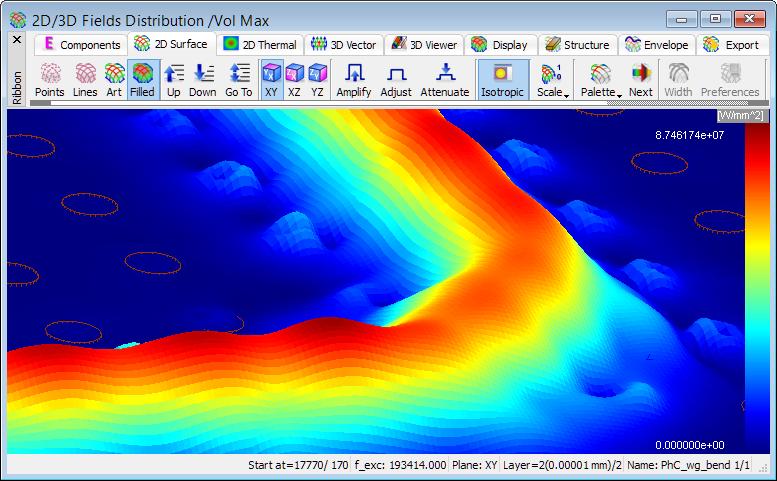
2 QWED has continued efforts on extending availability and functionality of the QuickWave software for electromagnetic design as well as the scope of its applications. The most visible change in QuickWave 2017 is the Ribbon GUI that appears in the QuickWave Editor and in QuickWave Simulator. All commands in the Ribbon are organised in a series of tabs divided in sections with grouped commands and contain various types of buttons and controls. QuickWave Editor is equipped in the main Ribbon containing all commands needed for creating complete project for FDTD electromagnetic simulation with QuickWave Simulator. QuickWave Simulator is equipped with the main Ribbon and window dedicated Ribbons containing all commands needed for running electromagnetic simulation, checking the FDTD mesh, observing the electromagnetic fields and components and getting the simulation results. For the convenience of the users, we kept the possibility of using the previous Toolbars style. The choice can be made during the first run of QuickWave Editor and QuickWave Simulator or later with the use of readily accessible commands from the menu. All main menus and windows menus in QuickWave Editor and in QuickWave Simulator were organised thematically, what provide easy access to options and commands. The new QuickWave Help system provides easier and faster access to the specific topics. The QuickWave Help system is divided into subcategories and is available from every window and dialog of QuickWave Editor and QuickWave Simulator. The Basic Heating Module is now enhanced with a wide variety of options, allowing defining complete BHM process directly from QuickWave Editor interface, which include intuitive configuration of Rotation Axes, Movement Trajectories, declaring variable heating steps etc. The effective and practically useful solution for simulation convergence monitoring has been introduced. It utilises monitoring of the electromagnetic (EM) energy in the calculation model and stopping the simulation when it decays to a certain level. This allows reducing the number of performed FDTD iterations and as a result the computing time, without reducing a computational accuracy. This solution is now available in QuickWave as Energy Stop Criterion feature. 2
3 RIBBON GUI IN QUICKWAVE EDITOR The Ribbon of QuickWave Editor groups all necessary menus and commands that guide the user during project preparation, setting of the simulation parameters, and simulation starting process. The Ribbon Home tab is arranged in ten sections enabling basic file operations like loading and saving projects, adjusting the project content view to user s preferences, setting access to external applications or format converters, managing windows and refreshing the project after introducing modifications, staying up to date with QuickWave updates, accessing main help, support, QWED s website, QuickWave End User Licence Agreement, exiting the QuickWave Editor and accessing help for Home commands. The Ribbon Model tab is arranged in thirteen sections enabling basic file operations like loading and saving projects, defining basic project settings, drawing geometry from UDO scripts, setting excitation type and its parameters, boundary conditions, meshing, and accessing help for Model commands. The Ribbon Simulation tab is arranged in five sections enabling basic file operations like loading and saving projects, defining post-processings, choosing QuickWave Simulator type, exporting the current project to QuickWave Simulator and starting simulation, and for user s convenience accessing help for Simulation commands. For the convenience of the users, we kept the possibility of using the previous Toolbars style. The choice can be made during the first run of QuickWave Editor or later with the use of readily accessible commands from the menu. 3
4 RIBBON GUI IN QUICKWAVE SIMULATOR QuickWave Simulator is equipped with the main Ribbon and window dedicated Ribbons containing all menus and commands necessary for running electromagnetic simulation, checking the FDTD mesh and using mesh testing tools, viewing a wide variety of simulation results including electromagnetic fields, exporting the simulation results and loading the previously saved results. For the convenience of the users, we kept the possibility of using the previous Toolbars style. The choice can be made during the first run of QuickWave Simulator or later with the use of readily accessible commands from the menu. 4
5 5


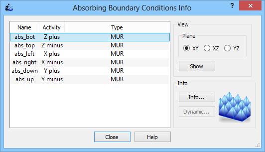
6 MORE CONVENIENT DIALOGUES IN QUICKWAVE EDITOR The QuickWave Editor user interface has been enhanced with a set of new intuitive dialogues, for introducing and editing parameters of the ports, probes, Absorbing Boundary Conditions, field monitors, etc., for introducing mesh snapping planes or configuring the post-processings. The new dialogues allow the user to introduce project parameters modification in an easy and convenient way. 6


7 QW-EDITOR LOG The QuickWave Editor user interface has been supplemented with the new QW-Editor Log window, which delivers a wide variety of information concerning the project that the user is working with. The displayed information include the warning/error messages issued by Parser UDO scripts interpreter, the activated Export Options notice, information regarding post-processings that has been activated for the project, etc. and also warning/error information issued by Export procedures. FDTD MESH TESTING TOOLS New set of testing tools is available for effective FDTD mesh grid. The testing tools allow inspecting the information regarding the effective FDTD mesh grid, including the position of the consecutive mesh lines along all three axis, the size of the following mesh cells, and additional information indicating if the cell is of minimum or maximum size generated for the project. Additional mechanism allowing finding the step in cell size between neighbouring FDTD cells, with user defined cell size ratio has been enabled. Moreover, the testing tools allow checking the position and dimensions of different simulation objects like, e.g. transmission line ports, MUR wall/box, NTF box, etc. 7

8 8


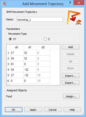
9 BHM IMPROVEMENTS The Basic Heating Module is now enhanced with a wide variety of options, allowing defining complete BHM process directly from QuickWave Editor user interface, which include intuitive configuration of Rotation Axes, Movement Trajectories, declaring variable heating steps etc. 9
10 10

11 In this version, the user is also allowed to enable saving in each BHM step, parameters other than temperature, e.g. enthalpy, effective media parameters, etc. AVERAGE TEMPERATURE For QW-BHM simulation, calculation of average temperature in the heated has been enabled. Two values of average temperature are available: arithmetic average temperature and volume average temperature. The average temperature is calculated separately for media with non-zero density (both lossy and lossless) and those with zero density (both lossy and lossless). 11
 energy in the calculation model and stopping the simulation automatically when it")
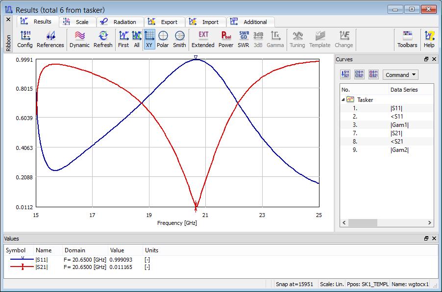
12 ENERGY STOP CRITERION The effective and practically useful solution for simulation convergence monitoring has been introduced. It is enabled for pulse excitation with a finite duration time and utilises monitoring of the electromagnetic (EM) energy in the calculation model and stopping the simulation automatically when it decays to a certain level. This allows reducing the number of performed FDTD iterations and as a result the computing time, without reducing computational accuracy. This solution is now available in QuickWave as Energy Stop Criterion feature, which is supplemented with several options additionally restricting the stop criterion, e.g. coupling the energy level with S-Parameters results fluctuations. S-PARAMETERS CORRECTION AROUND 0 GHZ The differential method of S-parameters extraction used in QuickWave converges slowly close to DC. This note is important for TEM transmission lines, where we may be interested in results close to DC. In the QuickWave 2017 the algorithm for S-parameters extraction has been extended to assure higher accuracy results near DC range. COLD PLASMA MATERIAL The new Cold Plasma material has been introduced. Its complex relative permittivity (including series losses) is given by single-pole Drude dispersion model with user-specified parameters. TOTAL ENERGY The total energy accumulated in the circuit and its variation with the simulation time is now available for viewing at any simulation stage. WAVEFORM The excitation waveform of all sources included in the project is now available for viewing at any simulation stage. As previously, the excitation waveform may be observed as it is generated and injected into the circuit and additionally, the entire excitation waveform may be viewed at any simulation stage from file, which is saved automatically by the software. 12
13 FREEZE WITH SUBTASKS Simulation freeze operation has been significantly extended and it is now available also while the certain subtasks e.g. Save_Full_Volume_Envelope are in progress. After unfreezing the simulation, the subtasks that were previously in progress will continue their calculations. NTF FREQUENCY BAND The radiation pattern and scattering pattern will be calculated at all frequencies specified by giving directly their values (as previously available) or by declaring the frequency range and frequency step between consecutive values. NEW HELP SYSTEM The new QuickWave Help system provides easier and faster access to the specific topics. The QuickWave Help system is divided into subcategories and is available from every window and dialogue of QuickWave Editor and QuickWave Simulator. OTHER 1. QW-BHM module allows for rotating metal objects, what is a significant extension of QW-BHM functionalities. 2. QW-BHM module allows for suspending and/or freezing the simulation after each or user defined number of BHM step. 3. QW-BHM allows for setting variable duration of consecutive heating steps. 4. The preview of Rotation and Movement process for QW-BHM projects has been enabled. 5. The diagnostic run for TEM template ports has been introduced. 6. Stability Factor Multiplier has been enabled for modifications in QuickWave Editor 7. QuickWave Editor has been adjusted to operation with several monitors. 8. The parameters list of Save_Volume_Instantaneous and Save_Full_Volume_Instantaneous subtasks has been extended with media effective parameters, e.g. EpsX, MuX, SigmaX, SigmaMX, Specific heat, etc. 9. Viewing previously saved Shape file (*.sh3) has been enabled. 10. New results file for NTF post-processing, containing radiation efficiency, radiation resistance, power radiated, power injected, and current injected by the source, saved automatically upon NTF results export/save command. SHORT-TERM LICENCES Short-term licences involve time periods from 1 month to 6 months and are available for QuickWave Professional package, QuickWave Standard package, and all QuickWave optional modules. The new licences are protected with a software licencing procedure. qwstore gives the possibility of getting quotation and purchasing short-term licence of your choice for QuickWave software. 13

14 Design is as simple as it can be. Simulation is as fast as you want it to be. Results are as accurate as they should be. QWED Sp. z o.o. ul. Krzywickiego 12 lok.1, Warsaw 14
A Graphical User Interface (GUI) for Two-Dimensional Electromagnetic Scattering Problems
 for Two-Dimensional Electromagnetic Scattering Problems") A Graphical User Interface (GUI) for Two-Dimensional Electromagnetic Scattering Problems Veysel Demir vdemir@olemiss.edu Mohamed Al Sharkawy malshark@olemiss.edu Atef Z. Elsherbeni atef@olemiss.edu Abstract
A Graphical User Interface (GUI) for Two-Dimensional Electromagnetic Scattering Problems Veysel Demir vdemir@olemiss.edu Mohamed Al Sharkawy malshark@olemiss.edu Atef Z. Elsherbeni atef@olemiss.edu Abstract
An Introduction to the Finite Difference Time Domain (FDTD) Method & EMPIRE XCcel
 Method & EMPIRE XCcel") An Introduction to the Finite Difference Time Domain (FDTD) Method & EMPIRE XCcel Simulation Model definition for FDTD DUT Port Simulation Box Graded Mesh six Boundary Conditions 1 FDTD Basics: Field components
An Introduction to the Finite Difference Time Domain (FDTD) Method & EMPIRE XCcel Simulation Model definition for FDTD DUT Port Simulation Box Graded Mesh six Boundary Conditions 1 FDTD Basics: Field components
Lecture 2: Introduction
 Lecture 2: Introduction v2015.0 Release ANSYS HFSS for Antenna Design 1 2015 ANSYS, Inc. Multiple Advanced Techniques Allow HFSS to Excel at a Wide Variety of Applications Platform Integration and RCS
CECOS University Department of Electrical Engineering. Wave Propagation and Antennas LAB # 1
 CECOS University Department of Electrical Engineering Wave Propagation and Antennas LAB # 1 Introduction to HFSS 3D Modeling, Properties, Commands & Attributes Lab Instructor: Amjad Iqbal 1. What is HFSS?
A Useful Tool for Analysis and Visualization of Grid Search Simulation Results
 A Useful Tool for Analysis and Visualization of Grid Search Simulation Results Przemysław Korpas and Mateusz Krysicki Institute of Radioelectronics, Warsaw University of Technology, Warsaw, Poland The
This is the script for the TEMP/W tutorial movie. Please follow along with the movie, TEMP/W Getting Started.
 TEMP/W Tutorial This is the script for the TEMP/W tutorial movie. Please follow along with the movie, TEMP/W Getting Started. Introduction Here is a schematic diagram of the problem to be solved. An ice
Autodesk Moldflow Insight AMI Cool Analysis Products
 Autodesk Moldflow Insight 2012 AMI Cool Analysis Products Revision 1, 22 March 2012. This document contains Autodesk and third-party software license agreements/notices and/or additional terms and conditions
Contents Contents Creating a Simulation Example: A Dipole Antenna AMDS User s Guide
 Contents Contents 1 Creating a Simulation 7 Introduction 8 Data Files for Examples 8 Software Organization 9 Constructing the Geometry 10 Creating the Mesh 11 Defining Run Parameters 13 Requesting Results
SIMULATION OF AN IMPLANTED PIFA FOR A CARDIAC PACEMAKER WITH EFIELD FDTD AND HYBRID FDTD-FEM
 1 SIMULATION OF AN IMPLANTED PIFA FOR A CARDIAC PACEMAKER WITH EFIELD FDTD AND HYBRID FDTD- Introduction Medical Implanted Communication Service (MICS) has received a lot of attention recently. The MICS
Air Movement. Air Movement
 2018 Air Movement In this tutorial you will create an air flow using a supply vent on one side of a room and an open vent on the opposite side. This is a very simple PyroSim/FDS simulation, but illustrates
Agilent W2100 Antenna Modeling Design System
 Agilent W2100 Antenna Modeling Design System User s Guide Agilent Technologies Notices Agilent Technologies, Inc. 2007 No part of this manual may be reproduced in any form or by any means (including electronic
Ribbon Functional Overview
 Ribbon Functional Overview JDA Space Planning JDA Floor Planning Release 2017.1.0.0 Legal Notice Rights to the content of this document Copyright 2017 JDA Software Group, Inc. All rights reserved. Printed
New Technologies in CST STUDIO SUITE CST COMPUTER SIMULATION TECHNOLOGY
 New Technologies in CST STUDIO SUITE 2016 Outline Design Tools & Modeling Antenna Magus Filter Designer 2D/3D Modeling 3D EM Solver Technology Cable / Circuit / PCB Systems Multiphysics CST Design Tools
Plane wave in free space Exercise no. 1
 Plane wave in free space Exercise no. 1 The exercise is focused on numerical modeling of plane wave propagation in ANSYS HFSS. Following aims should be met: 1. A numerical model of a plane wave propagating
Educational Web Series Maximo 7.6 Application Designer & Start Centers. Callie Straka 01/30/15
 Educational Web Series Maximo 7.6 Application Designer & Start Centers Callie Straka 01/30/15 About Cohesive Solutions Cohesive Solutions operates out of Kennesaw, Georgia. Cohesive provides business process
Autodesk Inventor Tips & Tricks Placing Features On
 1 Autodesk Inventor Tips & Tricks Placing Features On Cylindrical Shapes The adoption of parametric, feature based solid modeling will present many challenges to the new user as they are confronted for
Advance Excel Performing calculations on data 1. Naming groups of data 2. Creating formulas to calculate values
 Advance Excel 2013 Getting started with Excel 2013 1. Identifying the different Excel 2013 programs 2. Identifying new features of Excel 2013 a. If you are upgrading from Excel 2010 b. If you are upgrading
HeatWave Three-dimensional steady-state and dynamic thermal transport with temperature-dependent materials
 HeatWave Three-dimensional steady-state and dynamic thermal transport with temperature-dependent materials Field Precision Copyright 2001 Internet: www.fieldp.com E Mail: techninfo@fieldp.com PO Box 13595,
newfasant US User Guide
 newfasant US User Guide Software Version: 6.2.10 Date: April 15, 2018 Index 1. FILE MENU 2. EDIT MENU 3. VIEW MENU 4. GEOMETRY MENU 5. MATERIALS MENU 6. SIMULATION MENU 6.1. PARAMETERS 6.2. DOPPLER 7.
Aspects of RF Simulation and Analysis Software Methods. David Carpenter. Remcom. B = t. D t. Remcom (Europe)
") Remcom (Europe) Central Boulevard Blythe Valley Park Solihull West Midlands England, B90 8AG www.remcom.com +44 870 351 7640 +44 870 351 7641 (fax) Aspects of RF Simulation and Analysis Software Methods
Remcom (Europe) Central Boulevard Blythe Valley Park Solihull West Midlands England, B90 8AG www.remcom.com +44 870 351 7640 +44 870 351 7641 (fax) Aspects of RF Simulation and Analysis Software Methods
ANSYS FLUENT. Lecture 3. Basic Overview of Using the FLUENT User Interface L3-1. Customer Training Material
 Lecture 3 Basic Overview of Using the FLUENT User Interface Introduction to ANSYS FLUENT L3-1 Parallel Processing FLUENT can readily be run across many processors in parallel. This will greatly speed up
NX Fixed Plane Additive Manufacturing Help
 NX 11.0.2 Fixed Plane Additive Manufacturing Help Version #1 1 NX 11.0.2 Fixed Plane Additive Manufacturing Help June 2, 2017 Version #1 NX 11.0.2 Fixed Plane Additive Manufacturing Help Version #1 2 Contents
ANSYS Workbench Guide
 ANSYS Workbench Guide Introduction This document serves as a step-by-step guide for conducting a Finite Element Analysis (FEA) using ANSYS Workbench. It will cover the use of the simulation package through
HFSS - Antennas, Arrays and FSS's. David Perry Applications Engineer Ansoft Corporation
 HFSS - Antennas, Arrays and FSS's David Perry Applications Engineer Ansoft Corporation Synopsis Some Excerpts from What s New Enhancements to HFSS Wave Guide Simulator (WGS) What is it? Why you would use
ELC 4383 RF/Microwave Circuits I Laboratory 5: Circuit Tuning and Electromagnetic Simulation
 1 ELC 4383 RF/Microwave Circuits I Laboratory 5: Circuit Tuning and Electromagnetic Simulation Note: This lab procedure has been adapted from a procedure written by Dr. Tom Weller at the University of
LAB EXERCISE 3B EM Techniques (Momentum)
") ADS 2012 EM Basics (v2 April 2013) LAB EXERCISE 3B EM Techniques (Momentum) Topics: EM options for meshing and the preprocessor, and using EM to simulate an inductor and use the model in schematic. Audience:
ADS 2012 EM Basics (v2 April 2013) LAB EXERCISE 3B EM Techniques (Momentum) Topics: EM options for meshing and the preprocessor, and using EM to simulate an inductor and use the model in schematic. Audience:
Trident Trust PowerPoint User Guide
 Trident Trust PowerPoint User Guide Intelligent Documents October 2017 1 Overview The PowerPoint template is designed to make it quick and easy to create consistent and professional presentations conforming
Chapter 3. Thermal Tutorial
 Chapter 3. Thermal Tutorial Tutorials> Chapter 3. Thermal Tutorial Solidification of a Casting Problem Specification Problem Description Prepare for a Thermal Analysis Input Geometry Define Materials Generate
Outline. Darren Wang ADS Momentum P2
 Outline Momentum Basics: Microstrip Meander Line Momentum RF Mode: RFIC Launch Designing with Momentum: Via Fed Patch Antenna Momentum Techniques: 3dB Splitter Look-alike Momentum Optimization: 3 GHz Band
Laboratory Assignment: EM Numerical Modeling of a Stripline
 Laboratory Assignment: EM Numerical Modeling of a Stripline Names: Objective This laboratory experiment provides a hands-on tutorial for drafting up an electromagnetic structure (a stripline transmission
3D Body. Summary. Modified by Admin on Sep 13, Parent page: Objects
 3D Body Old Content - visit altium.com/documentation Modified by Admin on Sep 13, 2017 Parent page: Objects A sphere, a cylinder and 4 extruded rectangles have been used to create the 3D body for an LED.
TerraScan Tool Guide
 TerraScan Main Toolbox General Toolbar Draw Toolbar Groups Toolbar Vectorize Towers Toolbar Road Toolbar Buildings Toolbar Building Edges Toolbar View Laser Toolbar Model Toolbar Vectorize Wires Toolbar
CONTENTS Preface Introduction Finite Element Formulation Finite Element Mesh Truncation
 Preface xi 1 Introduction 1 1.1 Numerical Simulation of Antennas 1 1.2 Finite Element Analysis Versus Other Numerical Methods 2 1.3 Frequency- Versus Time-Domain Simulations 5 1.4 Brief Review of Past
TQPED MMIC Design Training
 TQPED MMIC Design Training Outline Installation and Use of the Library AWR AWR Design Kit (PDK Process Design Kit) ICED Layout Kit Create a new document using the Library Environment Setup Hotkeys Background
Workshop 3-1: Coax-Microstrip Transition
 Workshop 3-1: Coax-Microstrip Transition 2015.0 Release Introduction to ANSYS HFSS 1 2015 ANSYS, Inc. Example Coax to Microstrip Transition Analysis of a Microstrip Transmission Line with SMA Edge Connector
Autodesk Inventor 2019 and Engineering Graphics
 Autodesk Inventor 2019 and Engineering Graphics An Integrated Approach Randy H. Shih SDC PUBLICATIONS Better Textbooks. Lower Prices. www.sdcpublications.com Powered by TCPDF (www.tcpdf.org) Visit the
ADVANCED EXCEL Course Modules for Advance Excel Training Online (MS Excel 2013 Course):
:") Course Modules for Advance Excel Training Online (MS Excel 2013 Course): ADVANCED EXCEL 2013 1 Getting started with Excel 2013 A Identifying the different Excel 2013 programs B Identifying new features
Course Modules for Advance Excel Training Online (MS Excel 2013 Course): ADVANCED EXCEL 2013 1 Getting started with Excel 2013 A Identifying the different Excel 2013 programs B Identifying new features
Release Notes. MindManager 2019 for Windows MindManager Enterprise Version September 25, 2018
 Release Notes MindManager 2019 for Windows MindManager Enterprise 2019 Version 19.0 September 25, 2018 2018 Corel Corporation 1 Table of Contents USABILITY & PERFORMANCE IMPROVEMENTS... 3 User Interface...
Solved with COMSOL Multiphysics 4.3a
 Magnetic Lens Introduction Scanning electron microscopes image samples by scanning with a high-energy beam of electrons. The subsequent electron interactions produce signals such as secondary and back-scattered
Steady-State and Transient Thermal Analysis of a Circuit Board
 Steady-State and Transient Thermal Analysis of a Circuit Board Problem Description The circuit board shown below includes three chips that produce heat during normal operation. One chip stays energized
Using Tables, Sparklines and Conditional Formatting. Module 5. Adobe Captivate Wednesday, May 11, 2016
 Slide 1 - Using Tables, Sparklines and Conditional Formatting Using Tables, Sparklines and Conditional Formatting Module 5 Page 1 of 27 Slide 2 - Lesson Objectives Lesson Objectives Explore the find and
Manual for Wavenology EM Graphic Circuit Editor. Wave Computation Technologies, Inc. Jan., 2013
 Manual for Wavenology EM Graphic Circuit Editor Wave Computation Technologies, Inc. Jan., 2013 1 Introduction WCT Graphic Circuit Editor is used to build a Spice circuit model in WCT EM full wave simulator.
What s New in Access 2007
 What s New in Access 2007 This document provides a general overview of the new and improved features in Microsoft Access 2007. Opening Assurances 1. Functionality is the same; how we interact with the
Advanced Surface Based MoM Techniques for Packaging and Interconnect Analysis
 Electrical Interconnect and Packaging Advanced Surface Based MoM Techniques for Packaging and Interconnect Analysis Jason Morsey Barry Rubin, Lijun Jiang, Lon Eisenberg, Alina Deutsch Introduction Fast
CHAPTER 1 COPYRIGHTED MATERIAL. Finding Your Way in the Inventor Interface
 CHAPTER 1 Finding Your Way in the Inventor Interface COPYRIGHTED MATERIAL Understanding Inventor s interface behavior Opening existing files Creating new files Modifying the look and feel of Inventor Managing
LASCAD Tutorial No. 1: Modeling a laser cavity with end pumped rod
 LASCAD Tutorial No. 1: Modeling a laser cavity with end pumped rod Revised: January 15, 2009 Copyright 2006-2009 LAS-CAD GmbH Table of Contents 1 Starting LASCAD and Defining a Simple Laser Cavity...1
Isotropic Porous Media Tutorial
 STAR-CCM+ User Guide 3927 Isotropic Porous Media Tutorial This tutorial models flow through the catalyst geometry described in the introductory section. In the porous region, the theoretical pressure drop
LAB EXERCISE 2 EM Basics (Momentum)
") ADS 2012 EM Basics (v2 April 2013) LAB EXERCISE 2 EM Basics (Momentum) Topics: EM simulation in ADS, focusing on Momentum, including substrate and port setups, 3D viewing, visualization, and more. Audience:
ADS 2012 EM Basics (v2 April 2013) LAB EXERCISE 2 EM Basics (Momentum) Topics: EM simulation in ADS, focusing on Momentum, including substrate and port setups, 3D viewing, visualization, and more. Audience:
TABLE OF CONTENTS WHAT IS ADVANCE DESIGN? INSTALLING ADVANCE DESIGN... 8 System requirements... 8 Advance Design installation...
 Starting Guide 2019 TABLE OF CONTENTS INTRODUCTION... 5 Welcome to Advance Design... 5 About this guide... 6 Where to find information?... 6 Contacting technical support... 6 WHAT IS ADVANCE DESIGN?...
Chapter 4 Determining Cell Size
 Chapter 4 Determining Cell Size Chapter 4 Determining Cell Size The third tutorial is designed to give you a demonstration in using the Cell Size Calculator to obtain the optimal cell size for your circuit
Visio Price $ (inc GST)
") 1800 ULEARN (853 276) www.ddls.com.au Visio 2013 Length 2 days Price $913.00 (inc GST) Overview The skills and knowledge acquired in Microsoft Visio 2013 are sufficient to be able to create real-world
1800 ULEARN (853 276) www.ddls.com.au Visio 2013 Length 2 days Price $913.00 (inc GST) Overview The skills and knowledge acquired in Microsoft Visio 2013 are sufficient to be able to create real-world
Finite Element Analysis using ANSYS Mechanical APDL & ANSYS Workbench
 Finite Element Analysis using ANSYS Mechanical APDL & ANSYS Workbench Course Curriculum (Duration: 120 Hrs.) Section I: ANSYS Mechanical APDL Chapter 1: Before you start using ANSYS a. Introduction to
2. MODELING A MIXING ELBOW (2-D)
") MODELING A MIXING ELBOW (2-D) 2. MODELING A MIXING ELBOW (2-D) In this tutorial, you will use GAMBIT to create the geometry for a mixing elbow and then generate a mesh. The mixing elbow configuration is
MODELING A MIXING ELBOW (2-D) 2. MODELING A MIXING ELBOW (2-D) In this tutorial, you will use GAMBIT to create the geometry for a mixing elbow and then generate a mesh. The mixing elbow configuration is
Agilent Electromagnetic Design System
 Agilent 85270 Electromagnetic Design System Getting Started Agilent Technologies Notices Agilent Technologies, Inc. 2006 No part of this manual may be reproduced in any form or by any means (including
GraphWorX64 Productivity Tips
 Description: Overview of the most important productivity tools in GraphWorX64 General Requirement: Basic knowledge of GraphWorX64. Introduction GraphWorX64 has a very powerful development environment in
Introduction to Microsoft PowerPoint 2016
 Course 55176A: Introduction to Microsoft PowerPoint 2016 Course details Course Outline Module 1: Creating a PowerPoint Presentation This module explains how get started using Microsoft PowerPoint. Starting
Microsoft Visio 2010
 Microsoft Visio 2010 Bryton Burling Table of Contents Opening Microsoft Visio 2010... 2 Getting Started... 3 Creating a Conceptual Web Site Diagram... 3 Analyzing the Shapes Toolbar... 3 Adding a Home
Part 1: Resonance in a 2D cavity
 Problem 54: Microwave heating by harmonic M fields in a cavity Problem description In this problem, we analyze microwave heating in a cavity. In part 1, we analyze the harmonic electromagnetic field resonance
Ansoft HFSS 3D Boundary Manager
 and Selecting Objects and s Menu Functional and Ansoft HFSS Choose Setup / to: Define the location of ports, conductive surfaces, resistive surfaces, and radiation (or open) boundaries. Define sources
LAB # 2 3D Modeling, Properties Commands & Attributes
 COMSATS Institute of Information Technology Electrical Engineering Department (Islamabad Campus) LAB # 2 3D Modeling, Properties Commands & Attributes Designed by Syed Muzahir Abbas 1 1. Overview of the
Introduction to FEM calculations
 Introduction to FEM calculations How to start informations Michał Rad (rad@agh.edu.pl) 20.04.2018 Outline Field calculations what is it? Model Program How to: Make a model Set up the parameters Perform
3D PDF Plug-ins for Autodesk products Version 2.0
 Axes 3D PDF Plug-ins for Autodesk products Version 2.0 User Guide This end user manual provides instructions for the tetra4d - 3D PDF Plug-ins for Autodesk 203/204 applications. It includes a getting started
SETTLEMENT OF A CIRCULAR FOOTING ON SAND
 1 SETTLEMENT OF A CIRCULAR FOOTING ON SAND In this chapter a first application is considered, namely the settlement of a circular foundation footing on sand. This is the first step in becoming familiar
ME Week 12 Piston Mechanical Event Simulation
 Introduction to Mechanical Event Simulation The purpose of this introduction to Mechanical Event Simulation (MES) project is to explorer the dynamic simulation environment of Autodesk Simulation. This
403 Poyntz Avenue, Suite B Manhattan, KS PetraSim Example Manual
 403 Poyntz Avenue, Suite B Manhattan, KS 66502-6081 1.785.770.8511 www.thunderheadeng.com PetraSim Example Manual July 2007 TMVOC Example Guide Table of Contents 1.... 1 Description... 1 Specify the Simulator
Report Designer Report Types Table Report Multi-Column Report Label Report Parameterized Report Cross-Tab Report Drill-Down Report Chart with Static
 Table of Contents Report Designer Report Types Table Report Multi-Column Report Label Report Parameterized Report Cross-Tab Report Drill-Down Report Chart with Static Series Chart with Dynamic Series Master-Detail
A pipe bend is subjected to a concentrated force as shown: y All dimensions in inches. Material is stainless steel.
 Problem description A pipe bend is subjected to a concentrated force as shown: y 15 12 P 9 Displacement gauge Cross-section: 0.432 18 x 6.625 All dimensions in inches. Material is stainless steel. E =
JMAG-Designer Next Generation Electromagnetic Simulation Pre/Post System
 JMAG-Designer Next Generation Electromagnetic Simulation Pre/Post System Draft Engineering Technology Division JRI Solutions, Ltd. 1 Contents Introduction Transition from JMAG-Designer to JMAG Concept
Using Sonnet in a Cadence Virtuoso Design Flow
 Using Sonnet in a Cadence Virtuoso Design Flow Purpose of this document: This document describes the Sonnet plug-in integration for the Cadence Virtuoso design flow, for silicon accurate EM modelling of
system into a useful numerical model
 Simplification a ple process of a complex system into a useful numerical model Federico Centola, EMC Technologist, Apple inc 2011 IEEE EMC Society - Santa Clara Valley Chapter meeting EMC Simulations Full
Chapter 19 Assembly Modeling with the TETRIX by Pitsco Building System Autodesk Inventor
 Tools for Design Using AutoCAD and Autodesk Inventor 19-1 Chapter 19 Assembly Modeling with the TETRIX by Pitsco Building System Autodesk Inventor Create and Use Subassemblies in Assemblies Creating an
pre- & post-processing f o r p o w e r t r a i n
 pre- & post-processing f o r p o w e r t r a i n www.beta-cae.com With its complete solutions for meshing, assembly, contacts definition and boundary conditions setup, ANSA becomes the most efficient and
FLUENT Secondary flow in a teacup Author: John M. Cimbala, Penn State University Latest revision: 26 January 2016
 FLUENT Secondary flow in a teacup Author: John M. Cimbala, Penn State University Latest revision: 26 January 2016 Note: These instructions are based on an older version of FLUENT, and some of the instructions
v Data Visualization SMS 12.3 Tutorial Prerequisites Requirements Time Objectives Learn how to import, manipulate, and view solution data.
 v. 12.3 SMS 12.3 Tutorial Objectives Learn how to import, manipulate, and view solution data. Prerequisites None Requirements GIS Module Map Module Time 30 60 minutes Page 1 of 16 Aquaveo 2017 1 Introduction...
300 N All lengths in meters. Step load applied at time 0.0.
 Problem description In this problem, we subject the beam structure of problem 1 to an impact load as shown. 300 N 0.02 0.02 1 All lengths in meters. Step load applied at time 0.0. E = 2.07 10 11 N/m 2
HydroOffice Diagrams
 Hydro Office Software for Water Sciences HydroOffice Diagrams User Manual for Ternary 1.0, Piper 2.0 and Durov 1.0 tool HydroOffice.org Citation: Gregor M. 2013. HydroOffice Diagrams user manual for Ternary1.0,
WAIPA DISTRICT COUNCIL. Maps Online 9. Updated January This document contains an overview of IntraMaps/Maps Online version 9.
 WAIPA DISTRICT COUNCIL Maps Online 9 Updated January 2018 This document contains an overview of IntraMaps/Maps Online version 9.0 Contents Starting Maps Online... 3 Menu Bar... 4 Tools... 5 View Tab...
µ = Pa s m 3 The Reynolds number based on hydraulic diameter, D h = 2W h/(w + h) = 3.2 mm for the main inlet duct is = 359
 = 3.2 mm for the main inlet duct is = 359") Laminar Mixer Tutorial for STAR-CCM+ ME 448/548 March 30, 2014 Gerald Recktenwald gerry@pdx.edu 1 Overview Imagine that you are part of a team developing a medical diagnostic device. The device has a millimeter
Laminar Mixer Tutorial for STAR-CCM+ ME 448/548 March 30, 2014 Gerald Recktenwald gerry@pdx.edu 1 Overview Imagine that you are part of a team developing a medical diagnostic device. The device has a millimeter
CHAPTER 4. Numerical Models. descriptions of the boundary conditions, element types, validation, and the force
 CHAPTER 4 Numerical Models This chapter presents the development of numerical models for sandwich beams/plates subjected to four-point bending and the hydromat test system. Detailed descriptions of the
New Perspectives on Microsoft Excel Module 5: Working with Excel Tables, PivotTables, and PivotCharts
 New Perspectives on Microsoft Excel 2016 Module 5: Working with Excel Tables, PivotTables, and PivotCharts Objectives, Part 1 Explore a structured range of data Freeze rows and columns Plan and create
Heat Exchanger Efficiency
 6 Heat Exchanger Efficiency Flow Simulation can be used to study the fluid flow and heat transfer for a wide variety of engineering equipment. In this example we use Flow Simulation to determine the efficiency
Introduction. Inserting and Modifying Tables. Word 2010 Working with Tables. To Insert a Blank Table: Page 1
 Word 2010 Working with Tables Introduction Page 1 A table is a grid of cells arranged in rows and columns. Tables can be customized and are useful for various tasks such as presenting text information
Import a CAD Model 2018
 Import a CAD Model 2018 Import CAD Model In this tutorial you will import a CAD file, then add a 500 kw burner fire. Figure 1. Burner fire in this example This tutorial demonstrates how to: Import a CAD
Components User Guide Component Modeller
 Components User Guide Component Modeller IES Virtual Environment Copyright 2015 Integrated Environmental Solutions Limited. All rights reserved. No part of the manual is to be copied or reproduced in any
3D Surface Plots with Groups
 Chapter 942 3D Surface Plots with Groups Introduction In PASS, it is easy to study power and sample size calculations for a range of possible parameter values. When at least 3 input parameters vary, you
Autodesk Moldflow Insight AMI Analysis Overview Tutorial
 Autodesk Moldflow Insight 2012 AMI Analysis Overview Tutorial Revision 1, 30 March 2012. This document contains Autodesk and third-party software license agreements/notices and/or additional terms and
Caliber 11.0 for Visual Studio Team Systems
 Caliber 11.0 for Visual Studio Team Systems Getting Started Getting Started Caliber - Visual Studio 2010 Integration... 7 About Caliber... 8 Tour of Caliber... 9 2 Concepts Concepts Projects... 13 Baselines...
Tutorial 5: Working with Excel Tables, PivotTables, and PivotCharts. Microsoft Excel 2013 Enhanced
 Tutorial 5: Working with Excel Tables, PivotTables, and PivotCharts Microsoft Excel 2013 Enhanced Objectives Explore a structured range of data Freeze rows and columns Plan and create an Excel table Rename
Visit the following websites to learn more about this book:
 Visit the following websites to learn more about this book: 6 Introduction to Finite Element Simulation Historically, finite element modeling tools were only capable of solving the simplest engineering
SEAWAT 4 Tutorial - Example Problem
 SEAWAT 4 Tutorial - Example Problem Introduction About SEAWAT-4 SEAWAT-4 is the latest release of SEAWAT computer program for simulation of threedimensional, variable-density, transient ground-water flow
Autodesk Moldflow Insight AMI Modeling
 Autodesk Moldflow Insight 2012 AMI Modeling Revision 1, 21 March 2012. This document contains Autodesk and third-party software license agreements/notices and/or additional terms and conditions for licensed
WinGLink. Geophysical interpretation software VERSION
 WinGLink Geophysical interpretation software VERSION 2.21.08 WinGLink geophysical interpretation software WinGLink Geophysical interpretation software Essential tools for data QC, processing, and modeling
REVIT ARCHITECTURE 2016
 Page 1 of 6 REVIT ARCHITECTURE 2016 Revit Architecture 2016: CREATE A CHAMFERED COLUMN COMPONENT About creating a chamfered column family typical to the Victorian cottage style. Add the column to your
Visual Dialogue User Guide. Version 6.0
 Visual Dialogue User Guide Version 6.0 2013 Pitney Bowes Software Inc. All rights reserved. This document may contain confidential and proprietary information belonging to Pitney Bowes Inc. and/or its
The New Office 2007 Interface and Shared Features
 The New Office 2007 Interface and Shared Features The Ribbon and Ribbon Tabs Minimising and Maximising Keytips and shortcut keys Standard vs contextual tabs Live Preview Dialogue Box/ Task Pane launchers
New Capabilities in Project Hydra for Autodesk Simulation Mechanical
 New Capabilities in Project Hydra for Autodesk Simulation Mechanical Sualp Ozel, PE. Autodesk SM2447-L In this hands-on lab, we will go through several exercises and cover several new capabilities included
EXCITECH TOOLKIT for REVIT
 EXCITECH TOOLKIT for REVIT Index 1. WHAT'S NEW?... 3 New in Kobi Toolkit for Revit 2018.1... 3 2. GET STARTED... 3 About Kobi Toolkit... 3 Installation... 3 User interface... 5 Activating licence... 6
Perfect PDF 9 Premium
 Perfect PDF 9 Premium The test results ( gut Good, sehr gut very good) refer to Perfect PDF & Print 8 and to versions 7, 6 and 5 of Perfect PDF Premium Professionally create, convert, edit and view PDF,
An Example Eddy Currents
 An Example Eddy Currents Introduction To help you understand how to create models using the AC/DC Module, this section walks through an example in great detail. You can apply these techniques to all the
Wavenology BHA Manual with Tutorial Examples. Wave Computation Technologies, Inc. March, 2017
 Wavenology BHA Manual with Tutorial Examples Wave Computation Technologies, Inc. March, 2017 1 Outline GUI layout Project setting: Unit, Background, Boundary conditions, Frequency and Excitation Pulse