2017 TigerStop, LLC. TigerFence SLR. Installation Guide. February 2017 Mk1
|
|
|
- Rebecca Palmer
- 6 years ago
- Views:
Transcription


1 2017 TigerStop, LLC Installation Guide TigerFence SLR February 2017 Mk1 1


2 Serial Number Controller Controller Stand Mounting Brackets Controller Cable Solenoid Cable Power Cable Regulator Solenoid Valve Pneumatic Tubing Nut Pack Quick Reference Cards Nut Pack 2 Pneumatic Kit Drilling Template
3 Safety First! IMPORTANT SAFETY INFORMATION. READ ALL WARNINGS BEFORE OPERATING THIS PRODUCT. GENERAL WARNINGS WARNING: Installation of your TigerStop Product must be done by a person trained in the safe design and installation of automation products, and in the safe operation of power equipment. Ensure that such installation meets all legally required safety requirements and guidelines, and that proper guarding and safety devices are provided on all sides of the equipment to preclude unintended access during operation. Consult with and follow the recommendations of a qualifi ed safety engineer. WARNING: TigerStop Products are components intended for use in conjunction with potentially dangerous machinery. The use of TigerStop Products does not make other machinery safe. TigerStop Products are not intended to substitute, in any manner, for safe operating practices in general, or for safety features present in other machines designed to make those machines as safe as possible. TIGERSTOP PRODUCTS, IF USED OR INSTALLED IMPROPERLY, MAY CAUSE PERSONAL INJURY OR DEATH AND SHOULD ONLY BE OPERATED BY PERSONS TRAINED IN THEIR SAFE OPERATING PROCEDURES. Illustrations of TigerStop Products in use do not show, and are not intended to show, all safety features and practices necessary for their safe operation. INSTALLATION WARNINGS WARNING: TigerStop Products must be installed in accordance with all local, state, and federal regulations. Only personnel properly trained in the safe design and installation of automation machinery and related power equipment should install TigerStop Products onto other equipment, to ensure a safe and proper work station. TigerStop Products should not be operated without proper training, both in the operation of TigerStop Products, and in the operation of related equipment. IMPORTANT CAUTION: The motor box (compartment) contains DC voltage with potentially FATAL amperage. NEVER attempt any unauthorized actions inside the motor box. WARNING: Using a TigerStop interconnect does not relieve you of the responsibility for making sure that your saw or other tool has all the necessary safety equipment in place. All installations must meet all legally required safety requirements and guidelines. Installation and training should be done following the recommendations of a qualifi ed safety engineer. INTERCONNECTS OPERATION DANGER: This machine can start, move and stop automatically. Keep hands and loose clothing clear of moving parts while operating. Moving parts can crush and cut. When used with a saw or other cutting equipment, bodily injury and death may result if operated without safety guards on all machines. Do not operate with guards removed. Operators must wear adequate eye and ear protection. DANGER! Don t get pinched by the push feeder. Keep your hands away when in motion! 3
4 IMPORTANT SAFETY INFORMATION. READ ALL WARNINGS BEFORE OPERATING THIS PRODUCT. Keep the work area clean and well lighted to avoid accidental injury. Do not use TigerStop machines in a dangerous environment. Using power tools in damp or wet locations or in rain can cause shock or electrocution. Do not operate near fl ammable liquids or in gaseous or explosive atmospheres! Wear proper apparel, no loose clothes, long hair or jewelry which could get pulled into moving machinery or materials. Wear non slip footwear, safety glasses, ear protection and a dust mask. Use only 3- wire extension cords that have 3-prong grounding type plugs and 3-pole receptacles that accept the tools plug for 120VAC. Use only 5-wire cords and plugs when using 3 phase. Do not open motor compartment or controller keypad. DC Voltage with potentially FATAL amperage! Disconnect power before servicing. No user-serviceable parts inside. DO NOT operate this or any machine under the infl uence of drugs or alcohol! No one should operate this machine except for fully qualifi ed personnel. 4 Read the manual!
5 Table of Contents Installation Requirements...6 TigerFence SLR Installation...7 Enable Code...14 First Power Up...15 Find the End Limits Auto Detect Calibrate Set Kerf Set Units Set Optimizer Settings Basic TigerFence Functions...20 Entering Decimals Entering Fractions Calculator Mode Jog Increment PreSet Quick Calibration Working with Part Lists...24 Maintenance Schedule
6 Installation Requirements TigerFence SLR Power Requirements 110 VAC 15 Amps 208 VAC 20 Amps 240 VAC 20 Amps TigerFence SLR must have a dedicated circuit. No other equipment should be on the same circuit. WARNING! Do NOT use a high leg delta circuit to power TigerFence SLR. If you are not sure what kind of circuit you are using, STOP! Have a qualified electrician confirm the main power circuit. Do NOT drill or tap into the TigerStop beam! Drilling holes into the TigerStop beam may damage the drive system. All fastening or attachment to the fence beam must be made by inserting T-bolts or T-nuts with washers. Do NOT over tighten mounting hardware! It is critical, especially if not using the TigerStop Universal Attachment brackets, that the bolts are prevented from over tightening and driving into the fence beam. Always use washers. ALWAYS evenly tighten mounting hardware! Uneven tightening of mounting hardware can introduce a slight twist or other deformation in the beam. This will result in inaccurate measurement and premature failure of the drive belt or other components. NEVER open TigerStop Motor Box! The motor box compartment contains DC voltage with potentially FATAL amperage. NEVER attempt unauthorized actions inside the motor box! 6


7 TigerFence SLR Installation WARNING! WARNING! Read all instructions before performing installation! NEVER power up system while motor box is open! ALWAYS lock out/tag out TigerStop machinery before installing! TigerFence SLR Anatomy Cylinder Bracket Controller Motor Box TigerFence Mounting Slots (Back) Carriage Mount TigerFence to Saw Fold Along This Line Cutting Line - Edge of Saw Blade Maximum distance between holes on top line not more than mm Mark this line with center punches or scribe. 2 3/4 All holes 3/8-9.5mm Diameter End of TigerFence beam is here - DO NOT POSITION CLOSER TO SAW BLADE OR SEVERE DAMAGE TO YOUR MACHINE CAN OCCUR! TigerFence Drilling Template (Shipped in cardboard tube) 1. Remove the existing rip fence from the saw. Note: Set the fence and fence mounting bolts aside to be used later. Fence Removed 2. Lay the drilling template over the saw table and drill the mounting holes into the saw table and the spacer blocks, as shown on the template. 7


8 3. Attach TigerFence SLR to the table using the spacers and supplied hardware. Note: Ensure the TigerFence SLR is flush with the saw table top. Lock Washer Mount Fence to TigerFence Fence Square Adjustment Screws 8


9 4. Attach your existing ripping fence to the TigerFence SLR fence bracket. Note: You may need to drill the existing rip fence. Mount Anti-Kickback Teeth Control Drill & Tap 9


10 Connect to anti kick back lever Plumb Pneumatics Anti Kick Back Cylinder Solenoid Valve Regulator Main Air Input 10


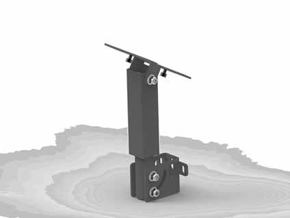

11 Install Controller Stand


12 Note: Attach the controller stand anywhere that is convenient for the machine operator. Set Range of Movement by Adjusting End Sensors End Sensors Loosen & Move 12
 Black")


13 Final Connections White End (Motor Box) Black End (Controller) Controller TigerStop Motor Box Controller Cable 15 Pin Solenoid Cable Solenoid TigerStop Motor Box 6 Pin Black TigerStop Power Cable Power Outlet TigerStop Motor Box Power Cable 13

 260-0755 service@tigerstop.")
14 Enable Code Your new TigerFence will not function until you enter the TigerStop enable code, which is supplied by TigerStop Customer Service. The enable code notifies TigerStop, LLC when your new TigerFence is about to be put into service. This lets us start the warranty on the exact day you turn it on. The enable code also allows TigerStop to turn on your TigerStop Dynamic Optimization upgrade. How to Enable TigerStop 1. Fill out the TigerStop Warranty Registration sheet that is shipped with your TigerFence controller. Fax or the registration to; (360) You may also register your warranty by phone; TigerStop Customer Service (360) TigerStop Customer Service will contact you by phone to give you the enable code, within the hour during regular business hours, Monday through Friday 6:00 am - 4:00 pm PST. 2. When you have received your enable code, power up TigerFence using the power switch on the motor box. 3. TigerFence will ask you to enter your enable code. Enter the code and press. Your TigerFence has now been enabled. Enabling Dynamic Optimization The Dynamic Optimization enable code upgrade is necessary to use TigerFence to its fullest potential. TigerFence can run an optimizing algorithm that will find the mathematically perfect way to cut your material. This can decrease material waste by up to 40%. Ask TigerStop Customer Service about Dynamic Optimization! 14

15 First Power Up After entering the enable code, TigerFence will ask to run the Home Routine. Home Routine Explained Every time TigerFence is powered up, it performs the Home Routine. The home routine is a 3 step process where TigerFence will move to its farthest possible position. 1. Press START to run the Home Routine. 2. When movement stops, TigerStop will display the Ready Screen. The Ready Screen is the starting point for all TigerStop functions. Let s take a look at the screen, line by line. Line 1 displays the heartbeat. The heartbeat is a line that rotates and lets you know that TigerFence is functioning normally. The letter next to the heartbeat is the drive indicator. This tells you what the motor is doing. Drive Indicator H A C D W S T X N Meaning Holding Still Accelerating Moving at Constant Speed Decelerating Waiting Stopping Waiting for Text Entry E-stop Error Communication Error Line 2 shows the current position of TigerFence. The position will show with in when in inches mode and mm when in metric mode. 15
16 Line 3 shows the next position of TigerFence. This is where user input is shown. Line 4 displays the soft key prompts. These prompts tell you what the soft key button below it does. These can change when you access different screens. Find the End Limits The Find end limits routine will make TigerFence physically move between the two end sensors and will automatically set the minimum and maximum limits. 1. From the Ready Screen, press the [Show] soft key to show the menu options. 2. Press the [Menu] soft key to display the Menu Select screen. 3. TigerFence requires a password to access all menu options. Enter your TigerFence password and press. Note: By default, the TigerFence password is set to the serial number. 4. At the Menu Select screen, press the [Setup] soft key to access the Setup Menu. 5. Press to scroll through the settings. Stop when you see FindLim. 6. Press [Start] to run the Find End Limit routine. Note: Ensure TigerFence can move its entire length without obstruction. TigerFence will move once START is pressed. When TigerFence has stopped moving, continue to the next set of instructions. Auto Detect 1. Press to scroll through the settings until you get to the Auto detect setting. 16
17 2. Follow the prompts on screen to detect your Interconnect Kit. Calibrate TigerStop 1. Press to scroll through the settings until you get to the Calib setting. 2. Measure how far the TigerStop is from your tool s zero point. 3. Enter this measurement and press the [Done] soft key. Note: TigerFence has been calibrated and you will be taken back to the Ready Screen. Set Kerf If the tool you have installed TigerStop to is a cutting tool, you will need to set the Kerf setting. The kerf is the measure of how much material is destroyed by the saw blade during a cut. 1. From the Ready Screen, press the [Show] soft key to show the menu options. 2. Press the [Menu] soft key to display the Menu Select screen. 3. TigerFence requires a password to access all menu options. Enter your TigerFence password and press. Note: By default, the TigerFence password is set to the serial number. 4. At the Menu Select screen, press the [Setup] soft key to access the Setup menu. 5. Press to scroll through the settings. Stop when you get to the Kerf setting. To measure kerf Rip a sample piece and measure it with a caliper. Record your measurement. 2. Rip this piece in half. 3. Put the two pieces together as if they were one piece and re-measure with a caliper. 4. The difference between the measurement on step 1 and the measurement on step 3 will be your Kerf value. 5. Enter your Kerf value and press the [Done] soft key to save the parameter. Note: It is important to check and reset the Kerf every time the saw blade is changed. 17
18 Set Units TigerFence can display its position in inches or metric. If you do not wish to change the units, skip this step. 1. From the Ready Screen, press the [Show] soft key to show the menu options. 2. Press the [Menu] soft key to display the Menu Select screen. 3. TigerFence requires a password to access all menu options. Enter your TigerFence password and press [=]. Note: By default, the TigerFence password is set to the serial number. 4. At the Menu Select screen, press the [Options] soft key to access the Options menu. 5. Press to scroll through the settings. Stop when you get to Units. 6. Press [B] to toggle between inches and metric. 7. Press the [Done] soft key when finished. Set Optimizer Settings TigerStops Dynamic Optimizer is tuned from the factory to give the best overall material yield. However, the optimizer can be configured differently if you have different requirements. 1. From the Ready Screen, press the [Show] soft key to show the menu options. 2. Press the [Menu] soft key to display the Menu Select screen TigerFence requires a password to access all menu options. Enter your TigerFence password and press [=]. Note: By default, the TigerFence password is set to the serial number.
19 4. At the Menu Select screen, press the [PartList] soft key to access the Part List menu. 5. Press to scroll through the settings until you get to the Opt Score setting. The Optimizer Score setting sets the score that the optimizer solution must reach to be considered a good solution. A lower Opt Score setting will give you a better optimized solution, but will take longer to do so. A higher Opt Score setting will give you a faster solution, but it may give you a lower material yield. To change Opt Score Enter the new Opt Score setting. 2. Press to save the parameter. 6. Press to scroll through the settings until you get to the Opt Time setting. The Optimizer Time setting sets the amount of time the TigerStop Optimizer has to find a solution. If it takes longer than this time, TigerStop will use the best found optimized solution. A lower Opt Time setting will give you a faster solution, but it may give you a lower material yield. A higher Opt Time setting will give you better material yield, but it may take longer to do so. To change Opt Time Enter the new Opt Time setting. 2. Press to save the parameter. 7. Press to scroll through the settings until you get to the Opt Pen setting. The Optimizer Penalty setting sets a penalty for multiple board optimized solutions. This means that the higher this setting, the more TigerFence will try to Rip wider parts first. A lower Opt Pen setting will give you faster optimization with more short parts processed first. A higher Opt Pen setting will give you a slower optimization with more long parts processed first. To change Opt Pen Enter the new Opt Pen setting. 2. Press to save the parameter. By adjusting these three optimizer settings, you can greatly influence how the TigerStop optimizer works to suit your exact application. 19
20 Basic TigerFence Functions Manual Movement To manually move TigerFence to a position, you must enter the length you want TigerFence to go to. This length can be entered as a decimal or a fractional value. Entering Decimals 1. Start at the Ready Screen. 2. Enter a length at the controller. Example: To enter 24 1/2 as a decimal, enter [2] [4] [.] [5]. Entering Fractions 3. Press [Start] to move TigerFence. 4. Start at the Ready Screen. 5. Enter a length at the controller. Example: To enter 24 1/2 as a decimal, enter [2] [4] [1] [/] [2]. START 6. Then press to move TigerFence. Notice that even though you entered a fraction, TigerFence will display the position as a decimal once it has moved. TigerFence cannot display fractions in the Position field. Calculator Mode TigerFence has a calculator function that can be used to do simple math problems. 1. Start at the Ready Screen. 20
21 Just like a normal calculator, you can use the math function keys to enter math problems. Example: I want to add 12 inches to 30 inches. Press [1] [2] [+] [3] [0]. The answer will appear in the Next field. 2. Press START and TigerFence will move to the calculated position. You can also do math functions on the current position. Example: I want to subtract 1.5 inches from my current position of 42 inches. 1. Press [-] [1] [.] [5]. The answer will appear in the Next field. 2. Press START and TigerFence will move. Jog TigerFence can be manually jogged in or out. When activated, TigerFence will move until you let go of the jog button. It will then glide to a gentle stop. 1. Start at the Ready Screen. 2. At the top of the TigerFence controller, you have a and a. To jog, press and hold one of these buttons. Note: If the jog buttons move TigerFence in the wrong direction, you can use the Jog Reverse setting in the Setup menu to reverse the movement. Increment The increment function is a push feed mode used to step TigerFence through a series of movements. Increment... Can be a positive value that will move TigerFence towards the tool. Can be a negative value that will move TigerFence away from the tool. Will compensate for kerf automatically using the Kerf setting in the Setup menu. Can only store one increment value at a time. 1. Start at the Ready Screen. 2. Press the [Show] soft key to display more options. 21
22 3. A new set of options have appeared. Press the [Incr] soft key to access the Increment menu. 4. Enter the size you want to increment and press. For this example, I am going to use an increment of 2 inches. 5. The current position is 42. If that is where you want to start, press START to begin incrementing. 6. When you are finished, press STOP to return to the Ready Screen. PreSet The PreSet function is a set of 100 programmable hot keys used to quickly access common lengths. PreSets... Can be used in Set Point, Pusher or Increment mode. Can be programed in PreSet slots number Note: PreSet functionality can be changed using the PreSet setting in the Part List menu. PreSet Programming 1. From the Ready Screen, press the [Show] soft key to show the menu options. 2. A new set of soft key options have appeared. Press the [PrSet] soft key to access the PreSet feature. 3. Enter the number of the preset you want to program and press the [Edit] soft key. 4. For this example, I am going to program PreSet number Enter the length you want the PreSet to move TigerFence to and press. For this example, I want to move to 15 15/16 inches. 22
23 6. The PreSet value is now set. 7. Press STOP to go back to the Ready Screen. Using the PreSet 1. Start at the Ready Screen. 2. Press the [PrSet] soft key to access the PreSet menu. 3. Enter the PreSet number you wish to use and press START. 4. TigerFence will move to the PreSet position. Deleting PreSets 1. Start at the Ready Screen. 2. Press the [PrSet] soft key to access the PreSet menu. 3. Enter the PreSet number you wish to delete and press the [Clear] soft key. 4. Press to clear. 5. TigerFence has now deleted the PreSet. Quick Calibration Quick calibration is a shortcut to the calibration setting. This allows advanced TigerFence users to quickly calibrate. 1. Start at the Ready Screen. Note: if you viewing the expanded options, press. 2. Measure how far the fence is from your saw blade. Enter this measurement and press the [Done] soft key. 3. TigerFence is now calibrated. 23
24 Working with Part Lists TigerFence has a versatile part list feature that allows users to enter large lists of parts for use with the TigerStop Dynamic Optimization upgrade. This lets the user run, view, edit, clear and optimize lists of parts, then processes the parts quickly and accurately. There are 4 types of lists that you can enter; Pusher A pusher list will tell TigerFence to push the stock material into the saw. Pusher lists can be optimized if you have the TigerStop Dynamic Optimizing upgrade. Set Point A set point list will tell TigerFence to act as a stop. It will treat each length you enter as an absolute value from your zero point. Set point lists can be optimized if you have the TigerStop Dynamic Optimizing upgrade. Pattern A pattern list will tell TigerFence to process one stock lengths worth of parts in a push feed fashion. It will run the same pattern of parts over and over until its told to stop. Pattern lists cannot be optimized. Pull A pull list works just like a pattern except it pulls away from the zero point instead of pushing towards it. Pull lists cannot be optimized. Programming a List 1. From the Ready Screen, press the [Show] soft key to show the menu options. 2. A new set of soft key options have appeared. Press the [List] soft key to access the List interface. 3. At the List interface, enter the list number you wish to program and press the [Edit] soft key. Note: The list number is a memory slot that houses the list. You can choose numbers Select the type of list you would like to program. 24
25 5. TigerFence will ask you if you want to optimize the list for material yield. If you choose no, TigerFence will process the list exactly as entered and will NOT optimize for material yield. 6. Select if you want to use a global or a local head and tail cut. Note: Head and tail cuts are trim cuts at the ends of your material. Global - Uses the head and tail cut setting from the Part List menu Local - Allows you to set a head and tail cut that is used for this list only. 7. You will now be taken to the programming screen for line 1. Enter the length of the part you wish to process and press. In this example, I will tell TigerFence I want to cut a 24 inch part. 8. The cursor will now drop to the quantity. Enter how many parts you want, followed by. In this example, I will tell TigerFence that I want 5 parts. 9. You will now be taken to line 2. Repeat steps 7 and 8 until you have entered all the parts you want to precess. Note: You can also download all the parts straight from your design file. Downloading is a faster way of importing parts for use with the TigerStop Optimizer. 10. Press the [Done] soft key when all parts are entered. 11. The list has now been saved. 12. Press START to run the list. 25
26 26
 1. Run a drive test to check machine drive.")

27 Maintenance Schedule Record the following settings for future reference. Serial Number: Min Limit: MxP = Max Limit: MxN = Scale: P+ = Kerf: P- = Lash: Drive Test Results Daily 1. Clean all dirt and debris from drive areas. 2. Check all cables for damage. 3. Check calibration, if necessary. Quarterly (Every 3 Months) 1. Run a drive test to check machine drive. The Drv, MxP and MxN measurements must be below Note: The drive test is inside the Debug menu. Yearly 1. Inspect the condition of the drive belt and replace if necessary. 2. Tighten belt. 1. Remove the black plastic motor cover. 2. Loosen the four motor mount bolts. 3. Pull down on the motor to tighten the belt. 4. Tighten the motor mount bolts. 5. Replace the motor cover. Loosen 27
28 Maintenance Log Date Maintenance Performed Drive Test Results 28
29 Maintenance Log Date Maintenance Performed Drive Test Results 29
30 30
31 31

32 FIND US ONLINE AT NE 95th Stree t Vancouver, WA sales@tigerstop.com TigerStop B.V. Holland info@tigerstop.nl 32
Made In America 2017 TigerStop, LLC. Tablet Package. Installation Guide. February 2017 Mk1
 Made In America 2017 TigerStop, LLC Installation Guide Tablet Package 1 February 2017 Mk1 Tablet PC Tablet PC Case Serial Cable USB Hub USB to Serial Converter Control Stand Hardware Pack 2 Top Mount Bottom
2017 TigerStop, LLC. Panel Saw Kit. Installation Guide. February 2017 Mk 1
 2017 TigerStop, LLC Installation Guide Panel Saw Kit 1 February 2017 Mk 1 Controller PowerHead Cable Guard Power Cable Stop Bar Support Leg Universal Bracket Flip Away Stop Assembly Bench Mount Brackets
2017 TigerStop, LLC. TigerStop. Ins. Register warranty and enable TigerStop Optimizer BEFORE installation! See Page 14! 1.
 2017 TigerStop, LLC Ins stallation lat Guide TigerStop Register warranty and enable TigerStop Optimizer BEFORE installation! February 2017 Mk1 See Page 14! 1 Serial Number Controller Controller Stand FlipAway
2017 TigerStop,LLC. Printer. February 2017 Mk1
 2017 TigerStop,LLC Printer 1 February 2017 Mk1 Printer Power Supply Power Cable I/O Panel w/ Cable RS232 Cable Printer Stand Optional 2 Tablet Package (Loaded with TigerPrint Display) Safety First! IMPORTANT
Installation Guide. TigerRack. Made In America 2017 TigerStop, LLC. Register warranty and enable TigerRack Optimizer BEFORE installation!
 Made In America 2017 TigerStop, LLC Installation Guide TigerRack Register warranty and enable TigerRack Optimizer BEFORE installation! February 2017 Mk1 See Page 15! 1 Serial Number I/O Panel Controller
2017 TigerStop, LLC. uid. TigerSPC. ation G. talllat. tal. Ins. February 2017 Mk1
 IIn Ins ns talllat uid ns stallation tal ation G Guide ui u iid de 2017 TigerStop, LLC TigerSC February 2017 Mk1 1 Serial Number TigerSC Standard Jaws Antenna Bench Mount Brackets Wireless Receiver ower
2017 TigerStop, LLC. TigerTouch. Installation Guide. February 2017 Mk2
 2017 TigerStop, LLC Installation Guide TigerTouch February 2017 Mk2 1 Enable Code If you are adding TigerTouch to a TigerStop product, you will need to update the Enable Code. The Enable Code unlocks TigerStop
TigerStop Ethernet-to-Serial Converter Installation & User s Guide v4.2
 E1 / 2010 ESC 4.2 TigerStop Ethernet-to-Serial Converter Installation & User s Guide v4.2 September 2010 TigerStop Version 5.03+ CONTACT: TigerStop LLC, Assembly Plant, 12909 NE 95 th St., Vancouver, WA
DANGER! Don't get pinched by the push feeder. Keep your hands away when in motion! Keep the work area clean and well lit to avoid accidental injury.
 Safety First! Any Automatic equipment can be dangerous if used improperly, and this includes TigerStop and its line of automation equipment: TigerStop, TigerPro, TigerFence (standard and SLR), TigerCrossCut,
1. Turn TigerStop ON.
 Version 5 These quick reference cards are for basic setup and use of all TigerStop products. If you require more detailed information, please refer to the TigerStop Manual at www.tigertamer.com D A N G
2017 TigerStop, LLC. Ins. TigerLink 6
 2017 TigerStop, LLC Ins stallation lat Guide TigerLink 6 January 2018 1 2 Safety First! IMPORTANT SAFETY INFORMATION. READ ALL WARNINGS BEFORE OPERATING THIS PRODUCT. GENERAL WARNINGS WARNING: Installation
Shop Fox Fence Kit Installation Instructions:
 Shop Fox Fence Kit Installation Instructions: Please note this installation kit is designed solely for installation on a Shop Fox Classic Fence. Accurate Technology manufactures kits for other saw fences
Biesemeyer Fence Kit Installation Instructions:
 Biesemeyer Fence Kit Installation Instructions: Please note this installation kit is designed solely for installation on a Biesemeyer Commercial Fence. Accurate Technology manufactures kits for other saw
3M Duplex Polishing Machine 6851-E with Universal Dual Holder Instructions
 3M Duplex Polishing Machine 6851-E with Universal Dual Holder Instructions Safety Information Read, understand and follow all safety information contained in these user instructions prior to use of the
Removal and Installation8
 8 Screw Types 8-4 Top Cover Assembly 8-5 Left Hand Cover 8-6 Right Hand Cover 8-10 Front Panel Assembly 8-14 Left Rear Cover 8-15 Right Rear Cover 8-16 Extension Cover (60" Model only) 8-17 Media Lever
Table of Contents: TOPIC: Safe Operation: READ THIS FIRST Page: 3 Warranty 4 Specifications 4 Installation 5-7 Operating Instructions 8 Parts Diagram
 INSTALLATION & OPERATIONS MANUAL FlexArm B-19 FlexArm Inc. Division of Midwest Specialties, Inc. 851 Industrial Drive Wapakoneta, Ohio 45895 419-738-8147 Book Part No 360740 12/2014 1 Table of Contents:
QUICK START GUIDE. Android or Windows Tablet. 1 Tower PC. Mount the RazorGage to your Own Table. Assembling the RazorGage ST with RazorGage Table
 QUICK START GUIDE Android or Windows Tablet If you have a Tablet Style Interface (PC or Android) then skip this step. 1 Mount monitor and attach legs to control tower using hardware provided and place
ABM International, Inc. Lightning Stitch Checklist 9/13/2013
 ABM International, Inc. Lightning Stitch Checklist 9/13/2013 1) Piggy backed board assembly (1) Piggy back board assembly tested? Yes No 24v passed XB passed XA passed YB passed YA passed SAFE passed S/S
Adapter Kit for PanelView 1200/1200e Touch Screen Terminal Cutout
 Installation Instructions Adapter Kit for PanelView 1200/1200e Touch Screen Terminal Cutout Catalog Numbers 2711-NR5T, 2711P-RAT12E2 Topic Page About This Publication 1 Important User Information 2 About
E1135C PDU and Pod Upgrade Procedure
 E4030-90010 Rev. B 12/2003 In this Document... Tools Needed, 2 Contents of the Upgrade Kits, 2 Installation Procedures, 4 Verifying the Power Option of the New PDU, 4 Removing the PDU from the Support
GV3000/SE Operator Interface Module (OIM) User Guide Version 2.0 M/N 2RK3000
 User Guide Version 2.0 M/N 2RK3000") GV3000/SE Operator Interface Module (OIM) User Guide Version 2.0 M/N 2RK3000 Instruction Manual D2-3342-2 The information in this manual is subject to change without notice. Throughout this manual, the
GV3000/SE Operator Interface Module (OIM) User Guide Version 2.0 M/N 2RK3000 Instruction Manual D2-3342-2 The information in this manual is subject to change without notice. Throughout this manual, the
Disconnect the battery to ensure there will be no shorted wires during the installation procedure.
 The round-style headunit receiver radio features Bluetooth technology allowing music to wirelessly stream from your compatible Bluetooth-enabled device. Control the audio from a distance -- all from your
Delta Unifence Kit Installation Instructions
 Delta Unifence Kit Installation Instructions Please note this installation kit is designed for installation on the Delta Commercial Unifence (units made between 1993 and current). Accurate Technology manufactures
Basketball Shot Clock Set LX2180 Manual
 Basketball Shot Clock Set LX2180 Manual 72 Industrial Boulevard Wrightsville, GA 31096 Phone: (800) 445-7843 Fax: (800) 864-0212 www.electro-mech.com LX2180 Revision 5 February 8, 2013 Table of Contents
DirectCommand Installation RoGator Model Year Ag Leader Technology
 Note: Indented items indicate parts included in an assembly listed above Part Name/Description Part Number Quantity Direct Command Kit 4100801 1 Dual Lock 2000052-9 1 Dual Lock 2000053-9 1 Quick Reference
Model: CAM430MV Wired Multi-View Camera with License Plate / Rear Surface Mount Installation Manual Features
 Model: CAM430MV Wired Multi-View Camera with License Plate / Rear Surface Mount Installation Manual Features Fully Adjustable, Multiple Viewing Angle Smart Camera. High Resolution, 1/2 CMOS Color Camera
Lightning Stitch Assembly
 ABM International, Inc. 1 1.0: Parts List Lightning stitch motor and drive assembly (Qty. 1) Lightning stitch piggy backed controller board assembly (Qty. 1) Touchscreen (Qty. 1) 2 9-pin Serial cable (Qty.
39 SLEEVE HITCH DISC OWNER S MANUAL
 39 SLEEVE HITCH DISC OWNER S MANUAL WARNING: Carefully read and understand all ASSEMBLY AND OPERATION INSTRUCTIONS before operating. Failure to follow the safety rules and other basic safety precautions
Delta Unifence Kit Installation Instructions
 Delta Unifence Kit Installation Instructions Please note this installation kit is designed for installation on the Delta Commercial Unifence (units made between 1993 and current). Accurate Technology manufactures
BS 287 DUAL CHANNEL POWER SUPPLY. User Manual. January 2017 V1.0
 BS 287 DUAL CHANNEL POWER SUPPLY User Manual January 2017 V1.0 Table of contents 1.0 SAFETY INSTRUCTIONS... 3 2.0 GENERAL DESCRIPTION PS 289... 4 3.0 MECHANICAL INSTALLATION... 5 4.0 MAINS POWER & SAFETY
MBE Mounts and Adapters
 MBE Mounts and Adapters MBE Series en Installation Guide MBE Mounts and Adapters Table of Contents en 3 Table of Contents 1 Important safety instructions 4 2 MBE Series Mounts and Adapters 6 2.1 Unpacking
ATV Single Row Disc Harrow OWNER S MANUAL
 ATV Single Row Disc Harrow OWNER S MANUAL WARNING: Read carefully and understand all ASSEMBLY AND OPERATION INSTRUCTIONS before operating. Failure to follow the safety rules and other basic safety precautions
H Manual Stretch Wrap Machine uline.com FILM ROLL CAPACITY TECHNICAL DATA ELECTRICAL SPECIFICATIONS TURNTABLE SPECIFICATIONS
 H-2304 Manual Stretch Wrap Machine 1-800-295-5510 uline.com SYSTEM SpecificationS IMPORTANT! Read this manual thoroughly and familiarize yourself with ALL controls and operating features. Keep this manual
Replacing the Galaxy II CRT Monitor with a Flat Screen Monitor Kit # 42638
 Replacing the Galaxy II CRT Monitor with a Flat Screen Monitor Kit # 42638 This kit contains detailed instructions on removing a Galaxy II Daewoo monitor and replacing it with a 19 wide flat screen monitor.
- ELV OVERVIEW. InstallationGuide SUPPLIED PARTS RELATED PARTS. Brackets Fixtures. Other. 1 of 9 IG-STR9-ELV
 OVERVIEW The STR9 ELV is a long run, low power, linear surface mount LED lighting system designed for exterior architectural lighting applications. This guide contains important information on planning
BS 181 SINGLE CHANNEL POWER SUPPLY USER MANUAL
 BS 181 SINGLE CHANNEL POWER SUPPLY USER MANUAL Issue 2011 ASL Intercom BV DESIGNED & MANUFACTURED BY: ASL Intercom B.V. Zonnebaan 42 3542 EG Utrecht The Netherlands Tel: +31 (0)30 2411901 Fax: +31 (0)30
Electric Multipliers Operating Instructions Rev 1.0
 The manual is a guide for operating the following Electric Multiplier models: Eliminator-EF, Eliminator-EF Plus, Eliminator-EFW, Eliminator-EFW Plus and Eliminator-EFR Eliminator-EF Eliminator-EF Plus
OV1000 Part No OV1000 HEIGHT ADJUSTABLE TABLE USER GUIDE
 OV1000 Part No. 23624 OV1000 HEIGHT ADJUSTABLE TABLE USER GUIDE PRODUCT OVERVIEW User Guide: OV1000 OV1000 HEIGHT ADJUSTABLE TABLE A healthier work environment starts with the option to sit or stand throughout
SAP Series IP Clock. Installation Manual V7.2. P. (+1) F. (+1)
 F. (+1)") Installation Manual V7. SAP Series IP Clock Current as of May 08 The Sapling Company, Inc. SAP Series IP Clocks Table of Contents Table of Contents Important Safety Instructions 3 Identify Your Clock 4
Installation Manual V7. SAP Series IP Clock Current as of May 08 The Sapling Company, Inc. SAP Series IP Clocks Table of Contents Table of Contents Important Safety Instructions 3 Identify Your Clock 4
Menus & Short Cuts. TigerStop Manual. Motion Menu. Operation Menu. Service Menu. Timer Menu Short Cut Keys 10 TS4-MSC. May 2006 Version 3.5 ~ 4.
 10 TS4-MSC TigerStop Manual Menus & Short Cuts May 2006 Version 3.5 ~ 4.72 Motion Menu Operation Menu Timer Menu Short Cut Keys Service Menu Contact information: TigerStop LLC, Assembly Plant, 12909 NE
Sapling Converter Box
 Installation Manual Sapling Converter Box SCB-100-000-1 Version Number 1.2 Current as of March 15, 2015 The Sapling Company, Inc. (+1) 215.322.6063 P. (+1) 215.322.8498 F. 2-Wire Converter Box (SCB-100-000-1)
Service Bulletin. MiTek. RoofTracker Roof Truss Roller Press. Machinery Affected: Adding an Operator Platform. Machinery Division
 MiTek Machinery Division Service Bulletin Machinery Affected: Document: Title: Applies To: RoofTracker Roof Truss Roller Press SB171 Adding an Operator Platform Frames 51 and Lower Copyright 2006 MiTek.
Force Test Stands Series ES. User s Guide
 User s Guide Force Test Stands Series ES MODEL ESM300 User s Guide Model ESM300 Programmable Force Test Stand Thank you Thank you for purchasing a Mark-10 ESM300 Programmable Force Test Stand, designed
BS 181 SINGLE CHANNEL POWER SUPPLY USER MANUAL
 BS 181 SINGLE CHANNEL POWER SUPPLY USER MANUAL August 2016 This product is designed and manufactured by: ASL Intercom B.V. Zonnebaan 42 3542 EG Utrecht The Netherlands Phone: +31 (0)30 2411901 Fax: +31
Paoloni Rip Kit Installation Instructions
 Paoloni Rip Kit Installation Instructions Please note this installation kit is designed for installation only on Paoloni P150, P260, P300 Sliding Table Saws, rip fence. Accurate Technology manufactures
Series Amp Pad Mount Quick Connect Input and Output Power Panels
 Series 300 2000-4000 Amp Pad Mount Quick Connect Input and Output Power Panels DANGER is used in this manual to warn of a hazard situation which, if not avoided, will result in death or serious injury.
SITRANS F. Flowmeters SysCom Upgrade Kit IP65 (NEMA 4X) Multi-Channel. Introduction 1. Installing/Mounting 2. Hardware Installation Instructions
 Multi-Channel. Introduction 1. Installing/Mounting 2. Hardware Installation Instructions") Introduction 1 Installing/Mounting 2 SITRANS F Flowmeters SysCom Upgrade Kit IP65 (NEMA 4X) Multi-Channel Hardware Installation Instructions 1/2010 A5E02518333A Revision 04 Legal information Warning notice
Introduction 1 Installing/Mounting 2 SITRANS F Flowmeters SysCom Upgrade Kit IP65 (NEMA 4X) Multi-Channel Hardware Installation Instructions 1/2010 A5E02518333A Revision 04 Legal information Warning notice
Ag Leader Technology. DirectCommand Installation RoGator Model Years
 Note: Indented items indicate parts included in an assembly listed above Part Name/Description Part Number Quantity Direct Command Kit 4100550 1 Dual Lock 2000052-9 1 Dual Lock 2000053-9 1 Hardware Kit
Quick Start Guide Ioline StudioJet
 Quick Start Guide Ioline StudioJet User Notice Trademarks Ioline StudioJet is a trademark of Ioline Corporation. HP is a trademark of the Hewlett-Packard Company. Other product names, logos, designs, titles,
A Axis M-Functions Level 1 A Axis Standard A Axis SMT Level 2. Each console includes the following:
 Hardware List The 3000M Crusader II Upgrade system has been custom configured to provide the necessary hardware required for installation on your machine. Verify that you have received all the correct
Installation and Operations Manual. Electronic copies available at (Rev_ )
") Installation and Operations Manual Electronic copies available at www.aquariitech.com/downloads/axceleronmanual Axceleron Installation and Operations Manual AXCELERON FIXTURE INSTALLATION... 1 Introduction...
Installation and Operations Manual Electronic copies available at www.aquariitech.com/downloads/axceleronmanual Axceleron Installation and Operations Manual AXCELERON FIXTURE INSTALLATION... 1 Introduction...
3 Indexer Installation For PRSalpha Tools
 888-680-4466 ShopBotTools.com 3 Indexer Installation For PRSalpha Tools Copyright 2016 ShopBot Tools, Inc. page 1 Copyright 2016 ShopBot Tools, Inc. page 2 Table of Contents General Safety and Precautions...5
Paoloni Rip Kit Installation Instructions
 Paoloni Rip Kit Installation Instructions Please note this installation kit is designed for installation only on Paoloni P320, P30N, and P30NP Sliding Table Saws, rip fence. Accurate Technology manufactures
TABLE OF CONTENTS TABLE OF CONTENTS... 1 IMPORTANT SAFETY NOTICE...
 TABLE OF CONTENTS TABLE OF CONTENTS... 1 IMPORTANT SAFETY NOTICE... 2 1.0 General Information... 3 1.1 System Components... 3 1.2 Specifications... 3 1.2.1 Torque Ranges... 3 1.2.2 Electrical Specifications...
Model No. ET-JPF200BE
 Operating Instructions Floor Stand Kit Commercial Use Model No. ET-JPF200BE ET-JPF200WE ENGLISH FRANÇAIS ESPAÑOL DEUTSCH ITALIANO * The above illustration is of this product mounted to an optional projector.
Whisper-Ride
 11/16/2007 LR (1) CAUTION: Before you begin any of the installation procedures on page 3, read and follow the warnings and safety instructions on this page. WARNING! THIS IS NOT A TOY! WARNING! CHILDREN
ATD Watt Fluorescent Underhood Light Owner s Manual
 ATD-80050 30-Watt Fluorescent Underhood Light Owner s Manual Features: Made in China to ATD Tools, Inc. Specifications Visit us at www.atdtools.com (Rev 0417) CA Prop 65 Warning: WARNING: This product
MAXIMA+ Series Rotary Level Indicator
 MAXIMA+ Series Rotary Level Indicator BinMaster: Division of Garner Industries 7201 N. 98th St., Lincoln, NE 68507 402-434-9102 email: info@binmaster.com www.binmaster.com OPERATING INSTRUCTIONS PLEASE
RAINPROOF* COLOR CAMERA SECURITY SYSTEM
 RAINPROOF* COLOR CAMERA SECURITY SYSTEM Model 91202 ASSEMBLY AND OPERATING INSTRUCTIONS 3491 Mission Oaks Blvd., Camarillo, CA 93011 Visit our Web site at: http://www.harborfreight.com Copyright 2004 by
5 B&W Rear View System Camera
 5 B&W Rear View System Camera Instruction Manual MODEL: CA453 www.lorexcctv.com Copyright 2007 LOREX Technology Inc. Thank you for purchasing the Lorex 5 Black & White Rear View System Camera. This system
Serial ATA Hot Swap Drive Cage Upgrade Kit for: Intel Server Chassis SC5200 Intel Server Chassis SC5250-E
 Serial ATA Hot Swap Drive Cage Upgrade Kit for: Intel Server Chassis SC5200 Intel Server Chassis SC5250-E A Guide for Technically Qualified Assemblers of Intel Identified Subassemblies/Products Order Number:
KM-4800w. Installation Guide
 KM-4800w Installation Guide TABLE OF CONTENTS page 1 Installation Requirements 2 2 Unpacking 3 2. 1 Unpacking 3 2. 2 Confirmation of Accessories 5 3 Leveling the Machine 7 4 Setup of the Roll Deck 9 5
ATD SABER 2000 LUMENS CORDED UNDERHOOD LIGHT OWNER S MANUAL
 ATD-80356 SABER 2000 LUMENS CORDED UNDERHOOD LIGHT OWNER S MANUAL FEATURES: 250 SMD LEDs provide 2,000 lumens of bright light Hooks extend 55 to 83 to t new SUV s and light trucks 40" light bar provides
Sidewinder Pumps Inc. AC Timer/Controller
 Sidewinder Pumps Inc. AC Timer/Controller Page 1 of 12 Rev 032417 Table of Contents 1. Warnings-------------------------------------------------------------------------------------------------- 3 1.1.
Model 2460-KIT. Screw Terminal Connector Kit. Description / September 2014 *P * 1
 Keithley Instruments 28775 Aurora Road Cleveland, Ohio 44139 1-800-935-5595 http://www.keithley.com Model 2460-KIT Screw Terminal Connector Kit Description The Model 2460-KIT Screw Terminal Connector Kit
TECHKNOW, INC. Kiosk Order Confirmation System INSTALLATION MANUAL. Revision Date: July 11, 2012 Part # Version 3.2
 document Page 1 of 18 TECHKNOW, INC Kiosk Order Confirmation System INSTALLATION MANUAL Revision Date: July 11, 2012 Part # Version 3.2 Techknow, Inc. 393 Mayfield Road Duncan, SC 29334 www.gotechknow.com
OV1001 Part No OV1001 HEIGHT ADJUSTABLE TABLE USER GUIDE
 OV1001 Part No. 23620 OV1001 HEIGHT ADJUSTABLE TABLE USER GUIDE PRODUCT OVERVIEW User Guide: OV1001 OV1001 HEIGHT ADJUSTABLE TABLE A healthier work environment starts with the option to sit or stand throughout
MAXIMA + Series ROTARY LEVEL CONTROL
 Price $5.00 MAXIMA + Series ROTARY LEVEL CONTROL OPERATING INSTRUCTIONS PLEASE READ CAREFULLY Division of Garner Industries 7201 North 98th Street Lincoln, NE 68507-9741 (402) 434-9102 925-0268 Rev. A
NE400 - LED MOTION LIGHT WITH VIDEO CAMERA
 USER MANUAL NE400 - LED MOTION LIGHT WITH VIDEO CAMERA Table of contents 1. Contents of package 2. NightWatcher NE400 Motion Light with Video Camera 3. Assembly 4. Installation 5. Programming your NightWatcher
InnoMedia Business VoIP ATA Models
 InnoMedia Business VoIP ATA Models MTA8328-4, MTA8328-8, MTA8328-24 Quick Installation Guide Important Safety Instructions Protective Earthing Protective earthing is used as a safeguard. This equipment
Integrated Valvejet 7 Dot Print Head
 Integrated Valvejet 7 Dot Print Head What am I getting? What are the improvements? Diagraph is proud to release the new IV7 Dot print head. New features include: Environmentally Sealed housing for harsh
Nov. 07, 2013 p. 5 - changed the B axis unit value to from Changed by Randy per Frank s request.
 Correction notes Nov. 07, 2013 p. 5 - changed the B axis unit value to 45.1389 from 40.0000. Changed by Randy per Frank s request. Jan. 22, 2018 p. 5 - changed the B axis unit value and corresponding picture
Cutter Option Installation Instructions
 This kit includes the parts and documentation necessary to install the cutter option on the Zebra XiII, XiIII, and XiIIIPlus-Series printers. NOTE: The Cutter Option is not available for the 96XiIII. Adding
Monitor - 15-Inch LCD - Replacement
 Haas Technical Documentation AD0107 Rev F Applies to machines built from: June, 2006 Monitor - 15-Inch LCD - Replacement Scan code to get the latest version of this document Translation Available Monitor
Series Amp Quick Connect Input and Output Power Panels
 Series 300 1200-1600 Amp Quick Connect Input and Output Power Panels DANGER is used in this manual to warn of a hazard situation which, if not avoided, will result in death or serious injury. WARNING is
MODEL K INSTRUCTION MANUAL CONTENTS
 MODEL 7173 - K INSTRUCTION MANUAL CONTENTS 1. MODEL 7173 - K ELECTRONIC FFU STEERING SYSTEM 2. MODEL 7173 - K COMPONENTS 3. MOUNTING THE 7173 - K AMPLIFIER UNIT 4. MOUNTING THE FFU CONTROLLER UNITS 5.
Torque Series LCD Remote Panel Installation/Operation Manual Model: TQ-DSP-12/24
 Torque Series LCD Remote Panel Installation/Operation Manual Model: TQ-DSP-12/24 Section Page Introduction 1 Materials Provided 1 I) Safety Instructions 1 A) Inverter Safety Instructions 1 B) Battery Safety
To connect the AC adapter:
 Replacing the AC Adapter Replacing the AC Adapter 3 Plug the power cord into a wall outlet. The power indicator turns on. To connect the AC adapter: Connect the power cord to the AC adapter. Power indicator
Pulse LED Instruction Guide
 PARTS LIST Light Fixture Aquarium Frame Mounts Instruction Guide WARNING: To guard against injury, basic precautions should be observed, including the following: A) READ AND FOLLOW ALL SAFETY INSTRUCTIONS.
Vacuum Maintenance Manual (EXCERPT Tim Benedict)
") 1. Position a ladder, scaffold, or work stand, on the right side of Vacuum Skid where the blower motors are installed. 2. Locate the six (6) vacuum hoses connecting the blower motors to the HEPA housings
1. Position a ladder, scaffold, or work stand, on the right side of Vacuum Skid where the blower motors are installed. 2. Locate the six (6) vacuum hoses connecting the blower motors to the HEPA housings
xtablet T1600 Vehicle Holder Installation Guide
 This document will step you through setting up the T1600 Vehicle Holder installation and tips for a safe, clean and long lasting installation. Preparing to Mount the Vehicle Holder Warning : Dock mounting
Assembly and Setup Manual
 M-12 Series Copyboard / C-12 Series Captureboard Assembly and Setup Manual This is the installation and assembly manual for the M-12 series Copyboard and C-12 series Captureboard. (The copyboard and/or
CDD4 Duct Carbon Dioxide Transmitter
 Drill or punch a 1-1/8 or 1-1/4 hole in the duct at the preferred location and insert the probe into the hole to mark the enclosure mounting holes. Remove the unit and drill the four mounting holes. Clean
APES-14 HD-6500 & HD-7000 Version Operator s Training Manual
 APES-14 HD-6500 & HD-7000 Version Operator s Training Manual Issue A1 09/03 PDI Part # 900600 Performance Design Inc. 2350 East Braniff St. Boise Idaho 83716 This manual contains very important safety
User Manual. 1U LCD Keyboard Drawer. KwikDraw - A Series. Manual. IT and Instrumentation for industry. - With KVM options - 15", 17, 19 screen size
 User Manual 1U LCD Keyboard Drawer KwikDraw - A Series - With KVM options - 15", 17, 19 screen size 1.1 Important Safeguards Please read all of these instructions carefully before you use the device. Save
RAM Rail Mount Kit RAM 201U 5 Arm RAM 2461U Monitor Mount RAM 235U Base, Double U-Bolt
 Note: Indented items indicate parts included in an assembly listed above Part Name/Description Part Number Quantity DirectCommand Kit 4100800 1 Cable Installation Kit 2000901-1 1 Dielectric Grease 2002872
SKIVING MACHINE MAINTENANCE & INSTRUCTIONS MANUAL ASSK2. Allswage UK. Roebuck Street, West Bromwich, B70 6RB
 SKIVING MACHINE ASSK2 MAINTENANCE & INSTRUCTIONS MANUAL A. WARRANTY AND RESPONSIBILITY Warranty: It's the supplier's responsibility to guarantee the conformity of the product, assuring that it's manufactured
Installing the Cisco MDS 9020 Fabric Switch
 CHAPTER 2 This chapter describes how to install the Cisco MDS 9020 Fabric Switch and its components, and it includes the following information: Pre-Installation, page 2-2 Installing the Switch in a Cabinet
Cellular Shades MOTORIZED SKYLIGHT. Simplicity with rechargeable batteries. Installation & Care Instructions
 Cellular Shades MOTORIZED SKYLIGHT Simplicity with rechargeable batteries Installation & Care Instructions 152741B 7/2/2018 GETTING STARTED A few simple tools are required: - Measuring tape - Power drill,
SAW Series Wi-Fi Clock
 Installation Manual V.0.7 SAW Series Wi-Fi Clock Current as of October 07 The Sapling Company, Inc. 670 Louis Drive Warminster, PA 8974 USA P. (+) 5.3.6063 SAW Series Wi-Fi Clocks Table of Contents Table
M215 (M215-60) Safety
 Safety") M215 QUICK INSTALL GUIDE M215 (M215-60) Safety Important Safety Information This document contains important instructions to use during installation and maintenance of the Enphase M215 Microinverter. To
M215 QUICK INSTALL GUIDE M215 (M215-60) Safety Important Safety Information This document contains important instructions to use during installation and maintenance of the Enphase M215 Microinverter. To
Daily use. indicating that the loud speakers
 BeoLab 8002 Guide WARNING: To reduce the risk of fire or electric shock, do not expose this appliance to rain or moisture. Do not expose this equipment to dripping or splashing and ensure that no objects
Neets Switching Relay - 2. Installation manual
 Neets Switching Relay - 2 Installation manual Foreword The purpose of this document is to describe how to install and configure Neets Switching Relay 2 with build-in power supply. COPYRIGHT - All information
Model 897 Operating Tutorial Alternators
 Model 897 Operating Tutorial Alternators MasterPower Switch MotorPower Switch Make sure that your 897 is connected to a 110VAC, 20A dedicated circuit. We recommend using a Square D HOM120HM or equivalent
MODEL SST3-MV INSTALLATION INSTRUCTIONS FOR FEDERAL MODEL SST3-MV SELECTABLE SIRENTONE-MULTI VOLT
 MODEL INSTALLATION INSTRUCTIONS FOR FEDERAL MODEL SELECTABLE SIRENTONE-MULTI VOLT INSTALLATION INSTRUCTIONS FOR FEDERAL MODEL SELECTABLE SIRENTONE-MULTI VOLT A. GENERAL. The Federal Model is a solid-state
ATV Single Gang Disc Harrow OWNER S MANUAL
 ATV Single Gang Disc Harrow OWNER S MANUAL WARNING: Read carefully and understand all ASSEMBLY AND OPERATION INSTRUCTIONS before operating. Failure to follow the safety rules and other basic safety precautions
E2460GS Oscilloscope Upgrade Kit
 Installation Instructions for E2460GS Oscilloscope Upgrade Kit Agilent 1670G-Series Logic Analyzers This kit upgrades either the Agilent Technologies 1670G, Agilent 1671G, Agilent 1672G, or the Agilent
Installing the Cisco SFS 3504 Server Switch
 CHAPTER 3 This chapter describes how to mount your Cisco SFS 3504 Server Switch on a rack, boot the Cisco SFS 3504 Server Switch, and configure basic services. For advanced configuration information, see
Instruction Manual. M Pump Motor Controller. For file reference, please record the following data:
 Instruction Manual M Pump Motor Controller For file reference, please record the following data: Model No: Serial No: Installation Date: Installation Location: When ordering replacement parts for your
E-37-V Dome Network Camera. Quick Start Guide
 E-37-V Dome Network Camera Quick Start Guide i Welcome Thank you for purchasing our Network camera! This user s manual is designed to be a reference tool for your system. Please read the following safeguard