2017 TigerStop, LLC. Panel Saw Kit. Installation Guide. February 2017 Mk 1
|
|
|
- Lucy Ross
- 6 years ago
- Views:
Transcription


1 2017 TigerStop, LLC Installation Guide Panel Saw Kit 1 February 2017 Mk 1


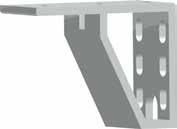


2 Controller PowerHead Cable Guard Power Cable Stop Bar Support Leg Universal Bracket Flip Away Stop Assembly Bench Mount Brackets Nut Pack 2 Measuring Bar
3 Safety First! IMPORTANT SAFETY INFORMATION. READ ALL WARNINGS BEFORE OPERATING THIS PRODUCT. GENERAL WARNINGS WARNING: Installation of your TigerStop Product must be done by a person trained in the safe design and installation of automation products, and in the safe operation of power equipment. Ensure that such installation meets all legally required safety requirements and guidelines, and that proper guarding and safety devices are provided on all sides of the equipment to preclude unintended access during operation. Consult with and follow the recommendations of a qualifi ed safety engineer. WARNING: TigerStop Products are components intended for use in conjunction with potentially dangerous machinery. The use of TigerStop Products does not make other machinery safe. TigerStop Products are not intended to substitute, in any manner, for safe operating practices in general, or for safety features present in other machines designed to make those machines as safe as possible. TIGERSTOP PRODUCTS, IF USED OR INSTALLED IMPROPERLY, MAY CAUSE PERSONAL INJURY OR DEATH AND SHOULD ONLY BE OPERATED BY PERSONS TRAINED IN THEIR SAFE OPERATING PROCEDURES. Illustrations of TigerStop Products in use do not show, and are not intended to show, all safety features and practices necessary for their safe operation. INSTALLATION WARNINGS WARNING: TigerStop Products must be installed in accordance with all local, state, and federal regulations. Only personnel properly trained in the safe design and installation of automation machinery and related power equipment should install TigerStop Products onto other equipment, to ensure a safe and proper work station. TigerStop Products should not be operated without proper training, both in the operation of TigerStop Products, and in the operation of related equipment. IMPORTANT CAUTION: The motor box (compartment) contains DC voltage with potentially FATAL amperage. NEVER attempt any unauthorized actions inside the motor box. WARNING: Using a TigerStop interconnect does not relieve you of the responsibility for making sure that your saw or other tool has all the necessary safety equipment in place. All installations must meet all legally required safety requirements and guidelines. Installation and training should be done following the recommendations of a qualifi ed safety engineer. INTERCONNECTS OPERATION DANGER: This machine can start, move and stop automatically. Keep hands and loose clothing clear of moving parts while operating. Moving parts can crush and cut. When used with a saw or other cutting equipment, bodily injury and death may result if operated without safety guards on all machines. Do not operate with guards removed. Operators must wear adequate eye and ear protection. DANGER! Don t get pinched by the push feeder. Keep your hands away when in motion! 3
4 IMPORTANT SAFETY INFORMATION. READ ALL WARNINGS BEFORE OPERATING THIS PRODUCT. Keep the work area clean and well lighted to avoid accidental injury. Do not use TigerStop machines in a dangerous environment. Using power tools in damp or wet locations or in rain can cause shock or electrocution. Do not operate near fl ammable liquids or in gaseous or explosive atmospheres! Wear proper apparel, no loose clothes, long hair or jewelry which could get pulled into moving machinery or materials. Wear non slip footwear, safety glasses, ear protection and a dust mask. Use only 3- wire extension cords that have 3-prong grounding type plugs and 3-pole receptacles that accept the tools plug for 120VAC. Use only 5-wire cords and plugs when using 3 phase. Do not open motor compartment or controller keypad. DC Voltage with potentially FATAL amperage! Disconnect power before servicing. No user-serviceable parts inside. DO NOT operate this or any machine under the infl uence of drugs or alcohol! No one should operate this machine except for fully qualifi ed personnel. 4 Read the manual!
5 Table of Contents Installation...6 SawGear Setup...12 Register Your Warranty Enable Your SawGear First Power Up Routine Basic SawGear Use...15 Moving SawGear Calibrating SawGear Using the Increment Feature Using the List Feature Sleep Mode Password Protection Switching Between Inches and Metric 5


6 Installation Install Universal Brackets to Saw Note: Drilling and Tapping may be required. Install Bench Mount Brackets to Universal Brackets 6


7 Attach SawGear Measuring Bar to Bench Mount Brackets Note: Ensure the Universal Brackets are level before attaching the SawGear Measuring Bar. Failure to do so will impact overall system accuracy. Assemble Support Leg Leveling Nuts 7


8 Attach Support Leg 8


9 Attach PowerHead to Measuring Bar Locking Handle Attach Cable Guard to PowerHead To attach the Cable Guard to the PowerHead, carefully remove the 4 screws on the back of the PowerHead. Hold the Cable Guard in place as shown and replace the 4 PowerHead screws. 9


10 Attach Flip Away to Carriage Assemble the Flip Away Stop as shown and attach it to the SawGear carriage. Tighten the Flip Away Stop so that it will stay up when its flipped to the up position. 10


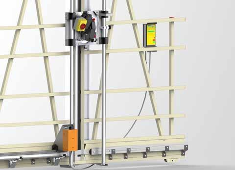

11 Install Stop Bar in Flip Away Stop Lock Attach Controller to Saw Note: Drilling and Tapping may be required. 11

 260-0755 service@tigerstop.")
12 Attach Power Cable to Controller SawGear Power 110 VAC 10 Amps SawGear requires a 110 vac, 10 amp dedicated circuit. This circuit must be properly grounded. WARNING! Do NOT use a high leg delta circuit to power SawGear! If you are not sure what kind of circuit you are using, STOP! Have a qualified electrician confirm the main power circuit. SawGear installation is now complete. SawGear Setup Register Your Warranty When your new SawGear arrives, you will find a warranty registration sheet in the accessory box. Fill out this form and fax or it to TigerStop Customer Service. (360) service@tigerstop.com TigerStop Customer Service will contact you by phone to give you your SawGear enable code, within the hour during regular business hours. Monday - Friday 6:00am - 4:00pm PST Also, feel free to call us if you would like an instant response. TigerStop Warranty Registration Please fill in your company information and fax this to TigerStop at (360) Your machine warranty begins on the date that you receive your enable code. Serial Number: Company Information Name of Company What is the street address of the TigerStop? Address We will send you an with your enable code. Please provide your address so we can send y important updates. Please be certain you can accept HTML format to ensure proper enable code delivery. Please call me with an enable code a Contact Name Tel Fax (360) Please select your industry Wood Industry Furniture Manufacturing Mouldings & Millwork Kitchen & Bath Cabinetry Wood Doors & Windows Commercial Fixtures Lumber & Panel Products Metal Industry Doors & Windows Other Sheet Metal Fabrication Plastic Industry Doors & Windows Other What problem(s) did you purchase the TigerStop to solve? Eliminate Setup Improve Accuracy Increase Productivity Improve Material Costs / Optomization Reduce Labor Costs Eliminate Rework Reduce Waste Increase Repeatability Where did you first hear about TigerStop? Word of mouth Used in a different job Metal Trade Show Dealer reccomended Wood Trade Show Mobile Showroom Internet Search Existing user This TigerStop is being used with (check one) Saw: Chop Saw Boring Machine Saw: Double Miter Drill Press Saw: Miter Mortiser Saw: Radial Arm Iron Workers Saw: Straightline Rip Punch Press Saw: Table Shears Saw: Up Cut Tube Bending Saw: Tube Cutter Custom Machinery: Other: 12
13 Enable Your SawGear Once you have registered your SawGear warranty, you can enter your SawGear enable code. Note: Your SawGear warranty begins on the day your SawGear is enabled. 1. When SawGear is powered up, the screen will ask for your enable code. 2. Enter the code given by TigerStop Customer Service and press. First Power Up Routine When SawGear is powered up for the first time, it will need to know a little bit about your saw setup. It will walk you through 3 questions. Note: The messages shown below will scroll across the screen if they are longer than 16 characters. 1. SawGear will ask which language you use. Press for English, for Spanish, for French, for Dutch or for German. 2. SawGear will ask which units you use. Press for Metric or for Inches. 3. SawGear will ask which side of the PowerHead the saw is attached to. Press for Left or for Right. 4. Ensure the table is clear. Press Start to begin the home routine. SawGear Home Routine SawGear will move as far away from the saw as possible SawGear will then move as far toward the PowerHead as it can SawGear will stop when finished Note: If SawGear doesn t do the routine in this exact order, you may have selected the saw side incorrectly. Remove the power cord and hold while plugging it back in to repeat the first start up routine. 5. SawGear will display its working length, as calculated during the home routine. Press to continue. 13
14 6. SawGear will now move back a few inches. Put a piece of material against the SawGear stop bar and cut it. 7. Measure the cut piece and enter into the SawGear keypad. Press when finished. 14
15 Basic SawGear Use Moving SawGear Moving SawGear is as easy as entering a length on the number pad and pressing to move. Lengths may be entered as decimals or as fractions. Entering Fractions Example: I want to cut a piece that is 2 feet and 8 and 1/2 inches. Enter. Press to move SawGear. Note: SawGear will now display lengths in fractions. Entering Decimals Example: I want to cut a piece that is 2 feet and 8 and 1/2 inches. Enter. Press to move SawGear. Note: SawGear will now display lengths in decimal. Number Pad Start Button 15
16 Calibrating SawGear As you use your SawGear, you will have to calibrate the length measurement after saw blade replacements or each time the machine is moved, before putting it into operation. How To Calibrate 1. Send SawGear to any length. 2. Make a cut and measure. 3. Press the button. 4. Enter your measurement and press. SawGear is now calibrated Calibrate Button Number Pad 16
17 Using the Increment Feature SawGear has an increment feature that allows you to move SawGear forward or backwards in set increments. Setting the Increment 1. Press. 2. Press the right or left increment button. 3. Enter the increment length for the selected button. 4. Press to save setting. Increment Button Calibrate Button How to Increment 1. When SawGear is at a length, press the right or left increment arrow SawGear will immediately move in the direction pressed. 17
18 Using the List Feature SawGear can store up to 9 dimensions in each of 10 cut list memory slots. Selecting a Memory Slot 1. Press. 2. Enter a memory slot number (0-9). 3. Press. Programming a List 1. Once you have selected a memory slot, Enter the length you want to cut. 2. Press to move to the next length. 3. Once you have programmed all the lengths you wish to program, Press to save the list. List Button Running a List 1. Press. 2. Enter the list number you wish to run Press to cycle through each programmed cut size. 18
19 Sleep Mode Sleep mode will turn off the SawGear display when left inactive for a set amount of time. 1. Press, then. 2. Enter the number of minutes that SawGear should remain powered up after inactivity. Note: The smallest value allowed is.25 minutes. Enter a value of 0 to disable sleep mode. 3. Press to enter the value. 4. Use to power up SawGear. Password Protection SawGear can be password protected to prevent its use by unauthorized persons. Please note that once the password is set, SawGear cannot be used without it. 1. Remove the power cable from the SawGear PowerHead. 2. Hold the button. 3. Plug the power cable back into the PowerHead while holding the button. 4. Press. 5. Enter any number, between 4-8 numbers in length. 6. Press. 7. Re-enter the password. 8. Press. 19
20 Deactivate Password Protection 1. Remove the power cable from the SawGear PowerHead. 2. Hold the button. 3. Plug the power cable back into the PowerHead while holding the button. 4. Press. 5. Enter the existing password and press. 7. Press. 8. Press. 9. The password is now deactivated. Switching Between Inches and Metric SawGear can switch between inches and metric during operation. 1. Press to power off the SawGear screen. 2. Press. 1. Press for Metric or for Inches. 2. Continue using SawGear as normal. 20
21 21
22 22
23 23
24 FIND US ONLINE AT NE 95th Stree t Vancouver, WA sales@tigerstop.com TigerStop B.V. Holland info@tigerstop.nl 24
Made In America 2017 TigerStop, LLC. Tablet Package. Installation Guide. February 2017 Mk1
 Made In America 2017 TigerStop, LLC Installation Guide Tablet Package 1 February 2017 Mk1 Tablet PC Tablet PC Case Serial Cable USB Hub USB to Serial Converter Control Stand Hardware Pack 2 Top Mount Bottom
2017 TigerStop,LLC. Printer. February 2017 Mk1
 2017 TigerStop,LLC Printer 1 February 2017 Mk1 Printer Power Supply Power Cable I/O Panel w/ Cable RS232 Cable Printer Stand Optional 2 Tablet Package (Loaded with TigerPrint Display) Safety First! IMPORTANT
2017 TigerStop, LLC. uid. TigerSPC. ation G. talllat. tal. Ins. February 2017 Mk1
 IIn Ins ns talllat uid ns stallation tal ation G Guide ui u iid de 2017 TigerStop, LLC TigerSC February 2017 Mk1 1 Serial Number TigerSC Standard Jaws Antenna Bench Mount Brackets Wireless Receiver ower
2017 TigerStop, LLC. TigerTouch. Installation Guide. February 2017 Mk2
 2017 TigerStop, LLC Installation Guide TigerTouch February 2017 Mk2 1 Enable Code If you are adding TigerTouch to a TigerStop product, you will need to update the Enable Code. The Enable Code unlocks TigerStop
2017 TigerStop, LLC. TigerFence SLR. Installation Guide. February 2017 Mk1
 2017 TigerStop, LLC Installation Guide TigerFence SLR February 2017 Mk1 1 Serial Number Controller Controller Stand Mounting Brackets Controller Cable Solenoid Cable Power Cable Regulator Solenoid Valve
TigerStop Ethernet-to-Serial Converter Installation & User s Guide v4.2
 E1 / 2010 ESC 4.2 TigerStop Ethernet-to-Serial Converter Installation & User s Guide v4.2 September 2010 TigerStop Version 5.03+ CONTACT: TigerStop LLC, Assembly Plant, 12909 NE 95 th St., Vancouver, WA
2017 TigerStop, LLC. TigerStop. Ins. Register warranty and enable TigerStop Optimizer BEFORE installation! See Page 14! 1.
 2017 TigerStop, LLC Ins stallation lat Guide TigerStop Register warranty and enable TigerStop Optimizer BEFORE installation! February 2017 Mk1 See Page 14! 1 Serial Number Controller Controller Stand FlipAway
Installation Guide. TigerRack. Made In America 2017 TigerStop, LLC. Register warranty and enable TigerRack Optimizer BEFORE installation!
 Made In America 2017 TigerStop, LLC Installation Guide TigerRack Register warranty and enable TigerRack Optimizer BEFORE installation! February 2017 Mk1 See Page 15! 1 Serial Number I/O Panel Controller
DANGER! Don't get pinched by the push feeder. Keep your hands away when in motion! Keep the work area clean and well lit to avoid accidental injury.
 Safety First! Any Automatic equipment can be dangerous if used improperly, and this includes TigerStop and its line of automation equipment: TigerStop, TigerPro, TigerFence (standard and SLR), TigerCrossCut,
2017 TigerStop, LLC. Ins. TigerLink 6
 2017 TigerStop, LLC Ins stallation lat Guide TigerLink 6 January 2018 1 2 Safety First! IMPORTANT SAFETY INFORMATION. READ ALL WARNINGS BEFORE OPERATING THIS PRODUCT. GENERAL WARNINGS WARNING: Installation
1. Turn TigerStop ON.
 Version 5 These quick reference cards are for basic setup and use of all TigerStop products. If you require more detailed information, please refer to the TigerStop Manual at www.tigertamer.com D A N G
3M Duplex Polishing Machine 6851-E with Universal Dual Holder Instructions
 3M Duplex Polishing Machine 6851-E with Universal Dual Holder Instructions Safety Information Read, understand and follow all safety information contained in these user instructions prior to use of the
ATD Watt Fluorescent Underhood Light Owner s Manual
 ATD-80050 30-Watt Fluorescent Underhood Light Owner s Manual Features: Made in China to ATD Tools, Inc. Specifications Visit us at www.atdtools.com (Rev 0417) CA Prop 65 Warning: WARNING: This product
Quick Start Guide Ioline StudioJet
 Quick Start Guide Ioline StudioJet User Notice Trademarks Ioline StudioJet is a trademark of Ioline Corporation. HP is a trademark of the Hewlett-Packard Company. Other product names, logos, designs, titles,
Ioline 300/350HF System
 Quick Start Guide Ioline 300/350HF System User Notice Trademarks Ioline is a trademark of Ioline Corporation. Other product names, logos, designs, titles, words or phrases mentioned within this publication
Shop Fox Fence Kit Installation Instructions:
 Shop Fox Fence Kit Installation Instructions: Please note this installation kit is designed solely for installation on a Shop Fox Classic Fence. Accurate Technology manufactures kits for other saw fences
ATD SABER 2000 LUMENS CORDED UNDERHOOD LIGHT OWNER S MANUAL
 ATD-80356 SABER 2000 LUMENS CORDED UNDERHOOD LIGHT OWNER S MANUAL FEATURES: 250 SMD LEDs provide 2,000 lumens of bright light Hooks extend 55 to 83 to t new SUV s and light trucks 40" light bar provides
ATD CORDED / CORDLESS 2000 LUMENS 2 IN 1 LED UNDERHOOD LIGHT OWNER S MANUAL
 ATD-80357 CORDED / CORDLESS 2000 LUMENS 2 IN 1 LED UNDERHOOD LIGHT OWNER S MANUAL FEATURES: 250 SMD LEDs provide 2,000 lumens of bright light Performance of a corded light with the convenience of a rechargeable
VOICE-ACTIVATED INTERCOM SYSTEM
 VOICE-ACTIVATED INTERCOM SYSTEM Owner s Manual For Wireless Intercom Model WHI-4CUPG EXPLANATION OF GRAPHIC WARNING SYMBOLS This symbol is intended to alert the user to the presence of un-insulated dangerous
Biesemeyer Fence Kit Installation Instructions:
 Biesemeyer Fence Kit Installation Instructions: Please note this installation kit is designed solely for installation on a Biesemeyer Commercial Fence. Accurate Technology manufactures kits for other saw
RAINPROOF* COLOR CAMERA SECURITY SYSTEM
 RAINPROOF* COLOR CAMERA SECURITY SYSTEM Model 91202 ASSEMBLY AND OPERATING INSTRUCTIONS 3491 Mission Oaks Blvd., Camarillo, CA 93011 Visit our Web site at: http://www.harborfreight.com Copyright 2004 by
LED FOLDING WORKLIGHT TM
 LED FOLDING WORKLIGHT TM LED LIGHT POWERSTRIP USB CHARGING ITM. / ART. 689211 Model: LM55812 CARE & USE INSTRUCTIONS IMPORTANT, RETAIN FOR FUTURE REFERENCE: READ CAREFULLY For assistance with assembly
DVI Detective. User Manual EXT-DVI-EDIDN. Release A3
 DVI Detective EXT-DVI-EDIDN User Manual Release A3 Important Safety Instructions 1. Read these instructions. 2. Keep these instructions. 3. Heed all warnings. 4. Follow all instructions. 5. Do not use
1:4 3GSDI Splitter. User Manual EXT-3GSDI-144. Release A5
 1:4 3GSDI Splitter EXT-3GSDI-144 User Manual Release A5 Important Safety Instructions 1. Read these instructions. 2. Keep these instructions. 3. Heed all warnings. 4. Follow all instructions. 5. Do not
Installing the Cisco SFS 3504 Server Switch
 CHAPTER 3 This chapter describes how to mount your Cisco SFS 3504 Server Switch on a rack, boot the Cisco SFS 3504 Server Switch, and configure basic services. For advanced configuration information, see
This 4200-RM Rack Mount Kit is for installation in 4200-CAB series cabinets only.
 Keithley Instruments, Inc. 28775 Aurora Road Cleveland, Ohio 44139 (440) 248-0400 Fax: (440) 248-6168 www.keithley.com Model 4200-RM Rack Mount Kit Packing List Introduction NOTE This 4200-RM Rack Mount
Basketball Shot Clock Set LX2180 Manual
 Basketball Shot Clock Set LX2180 Manual 72 Industrial Boulevard Wrightsville, GA 31096 Phone: (800) 445-7843 Fax: (800) 864-0212 www.electro-mech.com LX2180 Revision 5 February 8, 2013 Table of Contents
USB 2.0 SR. Extender over one CAT-5 Cable. User Manual EXT-USB2.0-SR. Version A1
 USB 2.0 SR Extender over one CAT-5 Cable EXT-USB2.0-SR User Manual Version A1 Important Safety Instructions 1. Read these instructions. 2. Keep these instructions. 3. Heed all warnings. 4. Follow all instructions.
Installing and Managing the Switch
 CHAPTER 2 This chapter describes how to install and manage the Cisco SFS 7008 system hardware and contains these sections: Safety, page 2-2 Preparing the Site, page 2-3 Rack-Mounting the Switch, page 2-4
Wa r n i n g-wa r n i n g-wa r n i n g
 Installation Instructions of the Power Analyzer Wa r n i n g-wa r n i n g-wa r n i n g Read and understand this manual before connecting device. Death, fire or serious injury can occur from using equipment
FUTURE CALL. Future Call Model FC-1204 Totally Hands Free Voice Activated Dialing and Answering Telephone OWNER S MANUAL AND OPERATING INSTRUCTIONS
 FUTURE CALL Future Call Model FC-1204 Totally Hands Free Voice Activated Dialing and Answering Telephone OWNER S MANUAL AND OPERATING INSTRUCTIONS Welcome to your new Totally Hands Free Voice Activated
345 Encinal Street Santa Cruz, CA
 Printed in the U.S.A. 69047-01 (11 04) 2000 2004 Plantronics, Inc. All rights reserved. Plantronics, the logo design, Plantronics and the logo design combined are trademarks or registered trademarks of
Now with Picture Memory
 Intrasonic Technology, Inc. Color Video Door Phone / Intercom Installer s Manual Model No.V304KIT-R Now with Picture Memory Please read this manual carefully before the products are installed.technical
Obtaining Documentation and Submitting a Service Request, page xvii Safety Warnings, page xvii Safety Guidelines, page xx
 Preface Obtaining Documentation and Submitting a Service Request, page xvii Safety s, page xvii Safety Guidelines, page xx Obtaining Documentation and Submitting a Service Request For information on obtaining
Removal and Installation8
 8 Screw Types 8-4 Top Cover Assembly 8-5 Left Hand Cover 8-6 Right Hand Cover 8-10 Front Panel Assembly 8-14 Left Rear Cover 8-15 Right Rear Cover 8-16 Extension Cover (60" Model only) 8-17 Media Lever
SPECIAL APPLICATION MANUAL PART NUMBER: TNP121UL. Tilt N Plug Jr. Table Top Interconnect Box USER'S GUIDE
 MANUAL PART NUMBER: 400-0429-001 TNP121UL Tilt N Plug Jr. Table Top Interconnect Box USER'S GUIDE INTRODUCTION Your purchase of the UL Listed TNP121UL, Tilt N Plug Jr. Interconnect Box is greatly appreciated.
Charging Cabinet Owner s Manual
 by edugear Charging Cabinet Owner s Manual Before using, please read these operating instructions carefully. They contain important advice concerning the use and safety of your Charging Cabinet. The Charging
TECHKNOW, INC. Kiosk Order Confirmation System INSTALLATION MANUAL. Revision Date: July 11, 2012 Part # Version 3.2
 document Page 1 of 18 TECHKNOW, INC Kiosk Order Confirmation System INSTALLATION MANUAL Revision Date: July 11, 2012 Part # Version 3.2 Techknow, Inc. 393 Mayfield Road Duncan, SC 29334 www.gotechknow.com
BS 181 SINGLE CHANNEL POWER SUPPLY USER MANUAL
 BS 181 SINGLE CHANNEL POWER SUPPLY USER MANUAL Issue 2011 ASL Intercom BV DESIGNED & MANUFACTURED BY: ASL Intercom B.V. Zonnebaan 42 3542 EG Utrecht The Netherlands Tel: +31 (0)30 2411901 Fax: +31 (0)30
Installation Instructions
 LUCCI Slim Line Fan Remote Control SKU# 210012 Rated Voltage 220-240V~ 50Hz Thank you for purchasing this quality Lucci product. To ensure correct function and safety, please read and follow all instructions
Model 2657A-LIM-3 LO Interconnect Module
 Keithley Instruments, Inc. 28775 Aurora Road Cleveland, Ohio 44139 1-888-KEITHLEY http://www.keithley.com Model 2657A-LIM-3 LO Interconnect Module User's Guide Description The Model 2657A-LIM-3 LO Interconnect
Model 2460-KIT. Screw Terminal Connector Kit. Description / September 2014 *P * 1
 Keithley Instruments 28775 Aurora Road Cleveland, Ohio 44139 1-800-935-5595 http://www.keithley.com Model 2460-KIT Screw Terminal Connector Kit Description The Model 2460-KIT Screw Terminal Connector Kit
PICTURE PHONE WITH ONE TOUCH DIALING MODEL: FC-0613
 FUTURE CALL PICTURE PHONE WITH ONE TOUCH DIALING MODEL: FC-0613 USER MANUAL Please follow instructions for repairing if any otherwise do not alter or repair any parts of device except specified. IMPORTANT
Adapter Kit for PanelView 1200/1200e Touch Screen Terminal Cutout
 Installation Instructions Adapter Kit for PanelView 1200/1200e Touch Screen Terminal Cutout Catalog Numbers 2711-NR5T, 2711P-RAT12E2 Topic Page About This Publication 1 Important User Information 2 About
GV3000/SE Operator Interface Module (OIM) User Guide Version 2.0 M/N 2RK3000
 User Guide Version 2.0 M/N 2RK3000") GV3000/SE Operator Interface Module (OIM) User Guide Version 2.0 M/N 2RK3000 Instruction Manual D2-3342-2 The information in this manual is subject to change without notice. Throughout this manual, the
GV3000/SE Operator Interface Module (OIM) User Guide Version 2.0 M/N 2RK3000 Instruction Manual D2-3342-2 The information in this manual is subject to change without notice. Throughout this manual, the
E1135C PDU and Pod Upgrade Procedure
 E4030-90010 Rev. B 12/2003 In this Document... Tools Needed, 2 Contents of the Upgrade Kits, 2 Installation Procedures, 4 Verifying the Power Option of the New PDU, 4 Removing the PDU from the Support
ATV Single Row Disc Harrow OWNER S MANUAL
 ATV Single Row Disc Harrow OWNER S MANUAL WARNING: Read carefully and understand all ASSEMBLY AND OPERATION INSTRUCTIONS before operating. Failure to follow the safety rules and other basic safety precautions
HypotULTRA. Quick Start Guide SAFETY CHECKLIST. Survey the test station. Make sure it is safe & orderly.
 EN 61010-1 EN 61010-31 Quick Start Guide HypotULTRA for the following models: 7800, 7820, 7850 SAFETY CHECKLIST Survey the test station. Make sure it is safe & orderly. Always keep unqualified/unauthorized
BS 287 DUAL CHANNEL POWER SUPPLY. User Manual. January 2017 V1.0
 BS 287 DUAL CHANNEL POWER SUPPLY User Manual January 2017 V1.0 Table of contents 1.0 SAFETY INSTRUCTIONS... 3 2.0 GENERAL DESCRIPTION PS 289... 4 3.0 MECHANICAL INSTALLATION... 5 4.0 MAINS POWER & SAFETY
5 B&W Rear View System Camera
 5 B&W Rear View System Camera Instruction Manual MODEL: CA453 www.lorexcctv.com Copyright 2007 LOREX Technology Inc. Thank you for purchasing the Lorex 5 Black & White Rear View System Camera. This system
3M AEROSPACE & COMMERCIAL TRANSPORTATION DIVISION St. Paul, MN USA or or Made in USA
 3M AEROSPACE & COMMERCIAL TRANSPORTATION DIVISION St. Paul, MN 55144-1000 USA www.3m.com/aerospace or 1-800-364-3577 or 1-800-235-2376 Made in USA with US and Globally Sourced Materials 3M 2015. All rights
CVU-3K-KIT. 3 kv Bias Tee Kit. Description. Parts list / October 2014 *P * 1
 Keithley Instruments 28775 Aurora Road Cleveland, Ohio 44139 1-800-935-5595 http://www.keithley.com CVU-3K-KIT 3 kv Bias Tee Kit Description The CVU-3K-KIT Bias Tee Kit consists of three bias tees for
SAFARI Montage Endpoint
 SAFARI Montage Endpoint Dear Customer, Thank you for the purchase of your new SAFARI Montage Endpoint! The SAFARI Montage Endpoint is the perfect complement to every display and projector, and it integrates
39 SLEEVE HITCH DISC OWNER S MANUAL
 39 SLEEVE HITCH DISC OWNER S MANUAL WARNING: Carefully read and understand all ASSEMBLY AND OPERATION INSTRUCTIONS before operating. Failure to follow the safety rules and other basic safety precautions
Quick Start Guide TS A
 Quick Start Guide TS 930 125-630A DANGER HAZARD OF ELECTRICAL SHOCK, EXPLOSION, OR ARC FLASH Read and understand this quick start guide before installing and operating the transfer switch The installer
DarkFX Spot 670 User Manual English
 DarkFX Spot 670 User Manual English 2016 Antari Lighting and Effects Ltd. 2 User Manual English Safety Information Please read the following safety information carefully before operating the fixture. Information
Delta Unifence Kit Installation Instructions
 Delta Unifence Kit Installation Instructions Please note this installation kit is designed for installation on the Delta Commercial Unifence (units made between 1993 and current). Accurate Technology manufactures
The power behind competitiveness. Delta Infrasuite Power Management. Power Distribution Unit. User Manual.
 The power behind competitiveness Delta Infrasuite Power Management Power Distribution Unit User Manual www.deltapowersolutions.com Save This Manual This manual contains important instructions and warnings
SKIVING MACHINE MAINTENANCE & INSTRUCTIONS MANUAL ASSK2. Allswage UK. Roebuck Street, West Bromwich, B70 6RB
 SKIVING MACHINE ASSK2 MAINTENANCE & INSTRUCTIONS MANUAL A. WARRANTY AND RESPONSIBILITY Warranty: It's the supplier's responsibility to guarantee the conformity of the product, assuring that it's manufactured
BIG BUTTON PHONE WITH ONE TOUCH DIALING AND
 FUTURE CALL LLC BIG BUTTON PHONE WITH ONE TOUCH DIALING AND 40db HANDSET VOLUME MODEL: FC-1507 USER MANUAL Please follow instructions for repairing if any otherwise do not alter or repair any parts of
SURFACE CONTROLTrack INSTALLATION INSTRUCTIONS
 SURFACE CONTROLTrack INSTALLATION INSTRUCTIONS IMPORTANT SAFETY INSTRUCTIONS - For use with CONTROLTrack System Only When installing or using this track system, basic safety precautions should always be
DVI ELR Extender over one CAT5
 DVI ELR Extender over one CAT5 EXT-DVI-1CAT5-ELR User Manual Release A3 Important Safety Instructions 1. Read these instructions. 2. Keep these instructions. 3. Heed all warnings. 4. Follow all instructions.
INSTALLATION INSTRUCTIONS
 INSTALLATION INSTRUCTIONS READ THIS MANUAL CAREFULLY! FAILURE TO INSTALL THIS EQUIPMENT PER THESE INSTRUCTIONS WILL VOID THE WARRANTY. AM16904-1 Rev. C pg. 1 of 12 SPECIAL NOTICES The following notices
BS 181 SINGLE CHANNEL POWER SUPPLY USER MANUAL
 BS 181 SINGLE CHANNEL POWER SUPPLY USER MANUAL August 2016 This product is designed and manufactured by: ASL Intercom B.V. Zonnebaan 42 3542 EG Utrecht The Netherlands Phone: +31 (0)30 2411901 Fax: +31
Table of Contents: TOPIC: Safe Operation: READ THIS FIRST Page: 3 Warranty 4 Specifications 4 Installation 5-7 Operating Instructions 8 Parts Diagram
 INSTALLATION & OPERATIONS MANUAL FlexArm B-19 FlexArm Inc. Division of Midwest Specialties, Inc. 851 Industrial Drive Wapakoneta, Ohio 45895 419-738-8147 Book Part No 360740 12/2014 1 Table of Contents:
Model 2380 Rack-Mount Kit
 Keithley Instruments 28775 Aurora Road Cleveland, Ohio 44139 1-800-935-5595 http://www.tek.com/keithley Model 2380 Rack-Mount Kit Installation Instructions Introduction The Model 2380 Fixed Rack-Mount
CVU-200-KIT. 200 V Bias Tee Kit. Description. Parts list / October 2014 *P A* 1
 Keithley Instruments 28775 Aurora Road Cleveland, Ohio 44139 1-800-935-5595 http://www.keithley.com CVU-200-KIT 200 V Bias Tee Kit Description The CVU-200-KIT Bias Tee Kit consists of three 2600-RBT-200
Installing the Cisco MDS 9020 Fabric Switch
 CHAPTER 2 This chapter describes how to install the Cisco MDS 9020 Fabric Switch and its components, and it includes the following information: Pre-Installation, page 2-2 Installing the Switch in a Cabinet
AutoRanging Digital MultiMeter
 Owner's Manual AutoRanging Digital MultiMeter Model No. 82175 CAUTION: Read, understand and follow Safety Rules and Operating Instructions in this manual before using this product. Safety Operation Maintenance
InnoMedia Business VoIP ATA Models
 InnoMedia Business VoIP ATA Models MTA8328-4, MTA8328-8, MTA8328-24 Quick Installation Guide Important Safety Instructions Protective Earthing Protective earthing is used as a safeguard. This equipment
Big button Speakerphone MODEL: FC-8814
 FUTURE CALL Big button Speakerphone MODEL: FC-8814 USER MANUAL Please follow instructions for repairing if any otherwise do not alter or repair any parts of device except specified. IMPORTANT SAFETY INSTRUCTIONS
Installation and Operations Manual. Electronic copies available at (Rev_ )
") Installation and Operations Manual Electronic copies available at www.aquariitech.com/downloads/axceleronmanual Axceleron Installation and Operations Manual AXCELERON FIXTURE INSTALLATION... 1 Introduction...
Installation and Operations Manual Electronic copies available at www.aquariitech.com/downloads/axceleronmanual Axceleron Installation and Operations Manual AXCELERON FIXTURE INSTALLATION... 1 Introduction...
Multi-Mount for Mac Pro " to 5.25" Drive Bay Converter Bracket. Assembly & Installation Manual
 Multi-Mount for Mac Pro 2009-2010 3.5" to 5.25" Drive Bay Converter Bracket Assembly & Installation Manual Introduction 1 INTRODUCTION 1.1 System Requirements 1.1.1 Computer Requirements 1.1.2 Hard Drive
Thank you for purchasing the CHP Assembly Tool. In order to ensure maximum performance and
 Power Supply Instruction Manual Applicable Models: APS-301A, APS-351B, APM-301A, APM-301C Thank you for purchasing the CHP Assembly Tool. In order to ensure maximum performance and product life, please
Dear Customer, User Memo: Please visit us on facebook or twitter! Thank you for purchasing this product.
 Dear Customer, Thank you for purchasing this product. For optimum performance and safety, please read these instructions carefully. User Memo: Date of purchase: Dealer name: Dealer address: Dealer website:
Removal and Installation 8
 Removal and Installation 8 8 Introduction 8-2 Service Calibration Guide to Removal and Installation 8-4 Window 8-8 Covers and Trims 8-12 Rear Tray 8-31 Rear Cover 8-32 Media Lever 8-33 Media Lever Position
Delta Unifence Kit Installation Instructions
 Delta Unifence Kit Installation Instructions Please note this installation kit is designed for installation on the Delta Commercial Unifence (units made between 1993 and current). Accurate Technology manufactures
MAXIMA+ Series Rotary Level Indicator
 MAXIMA+ Series Rotary Level Indicator BinMaster: Division of Garner Industries 7201 N. 98th St., Lincoln, NE 68507 402-434-9102 email: info@binmaster.com www.binmaster.com OPERATING INSTRUCTIONS PLEASE
Model No. ET-JPF200BE
 Operating Instructions Floor Stand Kit Commercial Use Model No. ET-JPF200BE ET-JPF200WE ENGLISH FRANÇAIS ESPAÑOL DEUTSCH ITALIANO * The above illustration is of this product mounted to an optional projector.
OV1001 Part No OV1001 HEIGHT ADJUSTABLE TABLE USER GUIDE
 OV1001 Part No. 23620 OV1001 HEIGHT ADJUSTABLE TABLE USER GUIDE PRODUCT OVERVIEW User Guide: OV1001 OV1001 HEIGHT ADJUSTABLE TABLE A healthier work environment starts with the option to sit or stand throughout
To connect the AC adapter:
 Replacing the AC Adapter Replacing the AC Adapter 3 Plug the power cord into a wall outlet. The power indicator turns on. To connect the AC adapter: Connect the power cord to the AC adapter. Power indicator
TABLE OF CONTENTS TABLE OF CONTENTS... 1 IMPORTANT SAFETY NOTICE...
 TABLE OF CONTENTS TABLE OF CONTENTS... 1 IMPORTANT SAFETY NOTICE... 2 1.0 General Information... 3 1.1 System Components... 3 1.2 Specifications... 3 1.2.1 Torque Ranges... 3 1.2.2 Electrical Specifications...
LevelOne KVM User Manual. 17 Modularized KVM Console V
 LevelOne KVM-0217 17 Modularized KVM Console User Manual V1.0.0-0708 SAFETY INSTRUCTIONS 1. Please read these safety instructions carefully. 2. Please keep this User Manual for later reference. 3. Please
Series Amp Pad Mount Quick Connect Input and Output Power Panels
 Series 300 2000-4000 Amp Pad Mount Quick Connect Input and Output Power Panels DANGER is used in this manual to warn of a hazard situation which, if not avoided, will result in death or serious injury.
IMPORTANT! USER MANUAL. LPU192CD Hi-Fi Turntable Stereo System WARRANTY INFORMATION INSIDE. PLEASE READ.
 LPU192CD Hi-Fi Turntable Stereo System USER MANUAL IMPORTANT! WARRANTY INFORMATION INSIDE. PLEASE READ Trademark of TEAC Corporation JAPAN www.teac.com.au 1 1 Read these Instructions. 2 Keep these Instructions.
Overview These instructions are presented as a guideline for installing and setting up the LX Series Breaker Control Panel.
 LX Breaker Control Panels Installation and Setup Procedure Hubbell Building Automation, Inc. 9601 Dessau Road Building One Suite 100 Austin, Texas 78754 512-450-1100 512-450-1215 Fax www.hubbell-automation.com
QUICK START GUIDE. Android or Windows Tablet. 1 Tower PC. Mount the RazorGage to your Own Table. Assembling the RazorGage ST with RazorGage Table
 QUICK START GUIDE Android or Windows Tablet If you have a Tablet Style Interface (PC or Android) then skip this step. 1 Mount monitor and attach legs to control tower using hardware provided and place
Dual Link DVI Extender
 2x Dual Link DVI Extender EXT-2DVI-CATDL User Manual Release A4 2x Dual Link DVI Extender Important Safety Instructions 1. Read these instructions. 2. Keep these instructions. 3. Heed all warnings. 4.
FUTURE CALL USER MANUAL PICTURE PHONE WITH SPEAKERPHONE MODEL: FC-1007 SP / PD
 FUTURE CALL PICTURE PHONE WITH SPEAKERPHONE MODEL: FC-1007 SP / PD USER MANUAL Please follow instructions for repairing if any otherwise do not alter or repair any parts of device except specified. IMPORTANT
MAXIMA + Series ROTARY LEVEL CONTROL
 Price $5.00 MAXIMA + Series ROTARY LEVEL CONTROL OPERATING INSTRUCTIONS PLEASE READ CAREFULLY Division of Garner Industries 7201 North 98th Street Lincoln, NE 68507-9741 (402) 434-9102 925-0268 Rev. A
Model 8020-STC. Kelvin Standard Triaxial Connector Card. Description / October 2014 *P * 1
 Keithley Instruments 28775 Aurora Road Cleveland, Ohio 44139 1-800-935-5595 http://www.keithley.com Model 8020-STC Kelvin Standard Triaxial Connector Card Description The Model 8020-STC Kelvin Standard
Bluetooth Ceiling Fan Control with App Owner's Manual
 READ AND SAVE THESE INSTRUCTIONS 0 Model Number RCBT00 Bluetooth Ceiling Fan Control with App Owner's Manual -Speed Hand Held Transmitter Single Light Supplied with Receiver Includes Light Dimming Selection
DSS Console and DSS Console for Attendant for Digital Super Hybrid Systems. Reference Guide ANSWER RELEASE
 ANSWER RELEASE PSQX1526ZA 98.8.5 7:32 PM Page 1 DSS Console and DSS Console for Attendant for Digital Super Hybrid Systems Reference Guide Model KX-T7440/KX-T7441 8 16 24 32 40 48 7 15 23 31 39 47 6 14
Installation Guide V290 (Color) This guide provides basic information for Unitronics LCD color touchscreen models V C30B and V T40B.
 This guide provides basic information for Unitronics LCD color touchscreen models V C30B and V T40B.") Vision OPLC Installation Guide V290 (Color) This guide provides basic information for Unitronics LCD color touchscreen models V290-19-C30B and V290-19-T40B. General Description Vision OPLCs are programmable
Vision OPLC Installation Guide V290 (Color) This guide provides basic information for Unitronics LCD color touchscreen models V290-19-C30B and V290-19-T40B. General Description Vision OPLCs are programmable
Series Amp Quick Connect Input and Output Power Panels
 Series 300 1200-1600 Amp Quick Connect Input and Output Power Panels DANGER is used in this manual to warn of a hazard situation which, if not avoided, will result in death or serious injury. WARNING is
Audio. one CAT-5 EXT-DVI-1CAT5-SR. User Manual. Release A2
 Audio DVI 3GSDI ELR Lite Embedder Extender over one CAT-5 EXT-DVI-1CAT5-SR User Manual Release A2 DVI ELR Lite Extender over one CAT-5 Important Safety Instructions 1. Read these instructions. 2. Keep
Operating and Installation Manual. EASYLAB Expansion modules Type EM-TRF for 230 V AC mains voltage
 Operating and Installation Manual EASYLAB Expansion modules Type EM-TRF for 230 V AC mains voltage Type EM-TRF-USV for 230 V AC mains voltage; provides uninterruptible power supply (UPS) The art of handling
Resolver to Digital Expansion Board
 Resolver to Digital Expansion Board Catalog No. EXB009A01 Installation and Operating Manual 6/98 MN1313 Table of Contents Section 1 General Information............................. 1-1 Introduction....................................
Operating Instructions
 Operating Instructions Model Numbers: LS LS M LS G LS A LS LS 00 LS M-WC LS A LS X LS M-WC LS B LS X LS M LS Dimensions A / B / C / D / E 0 / F / Electrical Information Voltage AMPS Frequency 0 HZ Single
Treadmill Integrated LCD Screen Option. Cardio Theater Integrated Bracket Assembly Instructions
 Treadmill Integrated LCD Screen Option Cardio Theater Integrated Bracket Assembly Instructions Table of Contents 1 2 3 4 5 6 Before You Begin... 4 Obtaining Service... 4 Unpacking the Equipment... 4 Important