The Existing DCT-Based JPEG Standard. Bernie Brower
|
|
|
- Jason Quinn
- 6 years ago
- Views:
Transcription
1 The Existing DCT-Based JPEG Standard 1
2 What Is JPEG? The JPEG (Joint Photographic Experts Group) committee, formed in 1986, has been chartered with the Digital compression and coding of continuous-tone still images Joint between ISO and ITU-T Has developed standards for the lossy, lossless, and nearly lossless of still images in the past decade Website: The JPEG committee has published the following standards: ISO/IEC ITU-T Rec. T.81 : Requirements and guidelines ISO/IEC ITU-T Rec. T.83 : Compliance testing ISO/IEC ITU-T Rec. T.84: Extensions ISO/IEC ITU-T Rec. T.86: Registration of JPEG Parameters, Profiles, Tags, Color Spaces, APPn Markers Compression Types, and Registration Authorities (REGAUT) 2
3 The Existing JPEG Standard Toolkit The existing JPEG standard concerns with the compression of continuous-tone, still-frame, monochrome and color images. It provides a "toolkit" of compression techniques from which applications can select the elements that satisfy their particular requirements. Baseline system: A simple and efficient DCT-based algorithm that uses Huffman coding, operates only in sequential mode, and is restricted to 8 bits/pixel input. Extended system: Enhancements to the baseline to satisfy broader applications. Lossless mode: Based on predictive coding and independent of the DCT that uses either Huffman or arithmetic coding. 3
4 JPEG Encoder Block Diagram 8x8 Blocks Header Compressed Data FDCT Quantizer Huffman Encoder Quantization Tables Huffman Tables 4
5 JPEG Decoder Block Diagram Header Compressed Data Reconstructed Image Data Huffman Decoder Dequantizer IDCT Huffman Tables Quantization Tables 5
, will reconstruct the original block.")
6 Image Representation with DCT DCT coefficients can be viewed as weighting functions that, when applied to the 64 cosine basis functions of various spatial frequencies (8 x 8 templates), will reconstruct the original block. = y(0,0) x + y(1,0) x + + y(7,7) x Original image block DC (flat) basis function AC basis functions 6
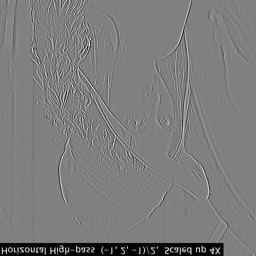
7 Original Image JPEG DCT Example BPP 64 pixels 512 bits DCT Transformed Image Quantized/ Scaled Transformed Data
8 DCT Coefficient Quantization Each DCT coefficient is uniformly quantized with a quantization step that is taken from a user-defined quantization table (q-table or normalization matrix), characterized by 64, 1-byte elements. The quality and compression ratio of an encoded image can be varied by changing the q-table elements (usually by scaling up or down the values of an initial q-table). The q-table is often designed according to the perceptual importance of the DCT coefficients (e.g., by using the HVS CSF data) under the intended viewing conditions. For the baseline system, in order to meet the needs of the various color components, up to four different quantization tables are allowed. 8
9 Example of Luminance Quantization Table The JPEG committee has listed the following luminance quantization table as an example in Annex K (informative) of the IS. It is obtained by measuring the DCT coefficient visibility threshold using CCIR-601 images and display, at a distance of six picture-heights away. QL( u, v) =
10 JPEG DCT Example After Quantization, the DCT is separated into a DC coefficient and AC coefficients, which are reordered into a 1- D format using a zigzag pattern in order to create long runs of zero-valued coefficients. The DC coefficient is directly correlated to the mean of the 8-by-8 block (upperleft corner). All DC coefficients are combined into a separate bit stream. The AC coefficients are the values of the cosine basis functions (all other values). DC 10
11 JPEG DCT Example DC AC EOB The DC coefficient is encoded using Huffman encoded 1D- DPCM The AC coefficients are encoded using Huffman coding on magnitude/runlength pairs (magnitude of a nonzero AC coefficient plus runlength of zero-valued AC coefficients that precede it). The end-of-block (EOB) symbol indicates that all remaining coefficients in the zigzag scan are zero. This allows many coefficients to be encoded with only a single symbol. 11
12 JPEG DCT Example Dequantized DCT Coefficients Reconstructed Image Error Image RMSE=
13 The Emerging JPEG2000 Standard 13
14 JPEG-DCT Pros and Cons Advantages Memory efficient Low complexity Compression efficiency Visual model utilization Robustness Disadvantages Single resolution Single quality No target bit rate No lossless capability No tiling No region of interest Blocking artifacts Poor error resilience 14


15 JPEG2000 Compression Paradigm Encode Decode Decode Choices Image resolution SNR fidelity Visual fidelity Target filesize Lossless/lossy Region-of-interest Tiles 15
16 Embedded Bitstream Application Lossless High quality Image 1 Image 2 Image 3 Image 4 16
17 JPEG2000 Objectives Advanced standardized image coding system to serve applications into the next millenium Address areas where current standards fail to produce the best quality or performance Provide capabilities to markets that currently do not use compression Provide an open system approach to imaging applications 17
18 JPEG2000: Requirements and Profiles Internet applications (World Wide Web imagery) Progressive in quality and resolution, fast decode Mobile applications Error resilience, low power, progressive decoding Digital photography Low complexity, compression efficiency Hardcopy color facsimile, printing and scanning Compression efficiency, strip or tile processing Digital library/archive applications Metadata, content management Remote sensing Multiple components, fast encoding, region of interest Medical applications Region of interest coding, lossy to lossless 18
19 JPEG2000 Features Improved compression efficiency (estimated 5-30% depending on the image size and bit rate) Lossy to lossless Multiple resolution Embedded bit stream (progressive decoding) Region of interest coding (ROI) Error resilience Bit stream syntax File format 19
20 JPEG2000 Compression Standard The standard only specifies a decoder and a bitstream syntax and is issued in several parts: Part I: specifies the minimum compliant decoder (e.g., a decoder that is expected to satisfy 80% of applications); International Standard (IS) is expected 12/2000. Part II: Describes optional, value added extensions; IS is expected in 12/2001. Other parts include: Motion JPEG2000 (Part III); Conformance Testing (Part IV); reference software in JAVA and C (Part V); file format for compound images (Part VI); and Technical Report outlining guidelines for minimum support of Part I (Part VII). 20
21 JPEG2000 Part I Encoder Original Image Data Discrete Wavelet Transform (DWT) Uniform Quantizer with Deadzone Compressed Image Data Adaptive Binary Arithmetic Coder 21
22 Benefits of DWT Multiple resolution representation Lossless representation with integer filters Better decorrelation than DCT, resulting in higher compression efficiency Use of visual models DWT provides a frequency band decomposition of the image where each subband can be quantized according to its visual importance (similar to the quantization table specification in JPEG-DCT) 22
23 JPEG2000 DWT Choices JPEG-2000 Part I only allows successive powers of two splitting of the LL band and the use of two DWT filters: The integer (5,3) filter provides fast implementation (faster than DCT) and lossless capability, but at the expense of some loss in coding efficiency. The Daubechies (9,7) floating-point filter that provides superior coding efficiency. The analysis filters are normalized to a DC gain of one and a Nyquist gain of 2. Part II allows for arbitrary size filters (user-specified in the header), arbitrary wavelet decomposition trees, and different filters in the horizontal vs. vertical directions. 23
24 The 1-D Two-Band DWT x(n) low-pass h 0 2 low-pass output h 1 2 high-pass high-pass output Analysis filter bank 24
25 Example of Analysis Filter Bank 1-D signal: Low-pass filter h 0 : ( )/8 High-pass filter h 1 : (-1 2-1)/2 Before downsampling: After downsampling:
26 26
27 27
28 28
29 Inverse DWT During the inverse DWT, each subband is interpolated by a factor of two by inserting zeros between samples and then filtering each resulting sequence with the corresponding lowpass, g 0, or high-pass, g 1, synthesis filters. The filtered sequences are added together to form an approximation to the original signal
30 The 1-D Two-Band DWT low-pass low-pass x(n) h g 0 y(n) h g 1 high-pass Analysis filter bank high-pass Synthesis filter bank Ideally, it is desired to choose the analysis filter banks (h 0 and h 1 ), and the synthesis filter banks (g 0 and g 1 ), in such a way so as to make the overall distortion zero, i.e., x(n) = y(n). This is called the perfect reconstruction property. 30
31 JPEG2000 Part I Encoder Original Image Data Discrete Wavelet Transform (DWT) Uniform Quantizer with Deadzone Compressed Image Data Adaptive Binary Arithmetic Coder Quantization step size can vary from one subband to another according to visual models (similar to JPEG Q- table specification). 31
32 Quantization in Part I Uniform quantization with deadzone is used to quantize all the wavelet coefficients. For each subband b, a basic quantizer step size b is selected by the user and is used to quantize all the coefficients in that subband. The choice of the quantizer step size for each subband can be based on visual models and is likened to the q-table specification in the JPEG DCT. b b b 2 b b b b
33 Embedded Quantization in Part I Unlike JPEG Baseline, where the resulting quantizer index q is encoded as a single symbol, in JPEG2000 it is encoded one bit at a time, starting from the MSB and proceeding to the LSB. During this progressive encoding, the quantized wavelet coefficient is called insignificant if the quantizer index q is still zero. Once the first nonzero bit is encoded, the coefficient becomes significant and its sign is encoded. If the p least significant bits of the quantizer index still remain to be encoded, the reconstructed sample at that stage is identical to the one obtained by using a UTQ with deadzone with a step size of b 2 p. 33
34 Embedded Quantization by Bit-Plane Coding 2 N-1 2 N-2 2 N MSB LSB 34
35 Embedded Quantization Example Wavelet coefficient = 83 Quantizer step size = 3 Quantizer index = 83/3 = 27 Quantizer index in binary: Decoded index after 6 BP s: = 6 Step size with 2 BP s remaining = 12 Quantizer index with step size of 12 = 6 Dequantized value = ( ) x 12 = 78 35
36 JPEG2000 Part I Encoder Original Image Data Discrete Wavelet Transform (DWT) Uniform Quantizer with Deadzone Compressed Image Data Adaptive Binary Arithmetic Coder Context-based adaptive binary arithmetic coding is used in JPEG2000 to efficiently compress each individual bit plane. 36
37 JPEG2000 Entropy Coder Each bit plane is further broken down into blocks (e.g., 64 x 64). The blocks are coded independently (i.e., the bit stream for each block can be decoded independent of other data) using three coding passes. The coding progresses from the most significant bit-plane to the least significant bit-plane. A coding block of a bit plane of a subband 37
38 JPEG2000 Entropy Coder The binary value of a sample in a block of a bit plane of a subband is coded as a binary symbol with the JBIG2 MQ- Coder that is a context-based adaptive arithmetic coder. Each bit-plane of each block of a subband is encoded in three sub bit plane passes instead of a single pass. The bitstream can be truncated at the end of each pass. This allows for: Optimal embedding, so that the information that results in the most reduction in distortion for the least increase in file size is encoded first. A larger number of bit-stream truncation points to achieve finer SNR scalability. 38
39 Significance Propagation Pass The first pass in a new bit plane is called the significance propagation pass. A symbol is encoded if it is insignificant but at least one of its eight-connected neighbors is significant as determined from the previous bit plane and the current bit plane based on coded information up to that point. These locations have the highest probability of becoming significant). The probability of the binary value at a given location of a bit-plane of a block of a subband is modeled by a context formed from the significance values of its neighbors. d v d h X h d v d 39
40 Refinement and Clean-up Passes Refinement (REF): Next, the significant coefficients are refined by their bit representation in the current bit-plane. Clean-up: Finally, all the remaining coefficients in the bitplane are encoded. (Note: the first pass of the MSB bit-plane of a subband is always a clean-up pass). The coding for the first and third passes are identical, except for the run coding that is employed in the third pass. The maximum number of contexts used in any pass is no more than nine, thus allowing for extremely rapid probability adaptation that decreases the cost of independently coded segments. 40
41 Sig. Prop. = 0 Bit plane 1 Refine = 0 Cleanup = 21 Total Bytes 21 Systems Engineering Compression ratio = : 1 RMSE = PSNR = db % refined = 0 % insig. =
42 Sig. Prop. = 38 Refine = 13 Cleanup = 57 Total Bytes 108 Systems Engineering Bit plane 3 Compression ratio = 1533 : 1 RMSE = PSNR = db % refined = 0.05 % insig. =
43 Sig. Prop. = 224 Refine = 73 Cleanup = 383 Total Bytes 680 Systems Engineering Bit plane 5 Compression ratio = 233 : 1 RMSE = PSNR = db % refined = 0.23 % insig. =
44 Sig. Prop. = 1243 Refine = 418 Cleanup = 1349 Total Bytes 3010 Systems Engineering Bit plane 7 Compression ratio = 47 : 1 RMSE = 6.02 PSNR = db % refined = 1.32 % insig. =

45 Sig. Prop. = 4593 Refine = 1925 Cleanup = 5465 Total Bytes Systems Engineering Bit plane 9 Compression ratio = 11.2 : 1 RMSE = 2.90 PSNR = db % refined = 6.01 % insig. =

46 Sig. Prop. = Refine = 8808 Cleanup = 5438 Total Bytes Systems Engineering Bit plane 11 Compression ratio = 2.90 : 1 RMSE = 0.90 PSNR = db % refined = % insig. =
47 Wavelet Bit Plane Compression Table BP JPEG-2K Bytes JPEG-2K PSNR-dB JPEG-2K RMSE JPEG Bytes JPEG PSNR JPEG RMSE * * * * * * * * * * level decomposition with (9,7) filter IJG code with default q-table * Filesize includes the header 47

48 Comparison of JPEG and JPEG-2000 JPEG, PSNR = db Filesize = 5804 Bytes JPEG-2K, PSNR = db Filesize = 5821 Bytes (BP 7) 48
49 Benefits of the JPEG2000 Entropy Coder Bit plane representation of data allows for embedded bit stream Region of interest coding (ROI) coding can be performed by prioritizing the coding of the ROI bit plane information Arithmetic coding allows for efficient compression of sparse binary data Context modeling allows for efficient compression of binary correlated data Packetized information allows for improved error resilience 49

50 Example of Bit Plane Reordering Subband 1 Subband 2 Subband 3 Subband 4 50
51 Example of Bit-Plane Reordering Code blocks BP BP BP Significance Refinement Clean-up BP LL HL LH HH 51

52 Example of Bit-Plane Data Ordering MSB BP 1 BP 2 Code blocks BP 3 BP 4 Significance Refinement Clean-up BP 5 BP 6 LL2 HL2 LH2 HH2 HL1 LH1 HH1 52
53 Lowest Resolution, Highest Quality BP 1 BP 2 BP 3 BP 4 BP 5 BP 6 LL2 HL2 LH2 HH2 HL1 LH1 HH1 53
54 Medium Resolution, Highest Quality BP 1 BP 2 BP 3 BP 4 BP 5 BP 6 LL2 HL2 LH2 HH2 HL1 LH1 HH1 54
55 Highest Resolution, Highest Quality BP 1 BP 2 BP 3 BP 4 BP 5 BP 6 LL2 HL2 LH2 HH2 HL1 LH1 HH1 55
56 Highest Resolution, Target Visual Quality BP 1 BP 2 BP 3 BP 4 BP 5 BP 6 LL2 HL2 LH2 HH2 HL1 LH1 HH1 56
, the LL subband is included. Decomposition levels run from 1 to N L.")
57 Resolution & Decomposition Levels Resolution level 0 Decomposition level 4 Decomposition level 3 4LL 4HL 4LH 4HH 3LH 3HL 3HH 2HL 1HL Decomposition level 2 2LH 2HH Decomposition level 1 1LH 1HH Decomposition level A set of HL, LH, and HH subbands. For the last level of decomposition (N L ), the LL subband is included. Decomposition levels run from 1 to N L. Resolution level Related to decomposition angle by n = N L r, where n is a decomposition level and r is a resolution level. Reconstruction levels run from N L to 0. 57
58 Code Blocks, Packets & Precincts Code blocks divide subbands into regions that may be extracted independently A rectangular grouping of coefficients from the same subband Code blocks do not scale with levels Packets Part of the compressed bitstream. Contains packet header & compressed image data from one layer of one precinct of one decomposition level Contains compressed image data from all code blocks of a given resolution level (nhl, nlh, and nhh subbands) Precinct Rectangular region within a decomposition level used to limit the size of packets Subbands with more than one precinct, have multiple packets in a given layer. Code block Subband boundary Precinct boundary 58
59 Layer Formation Least important bits Layer Most important bits Code block Layer An arbitrary collection of compressed image data from coding passes of one or more code blocks. Typically a layer represents an improvement in image quality. Packet headers describe the contribution of each code block in each layer 59
60 JPEG 2000 Progression Types After wavelet processing, we have a four dimensional cube of data Spatial/Resolution (two) Component Bitdepth JPEG 2000 allows progression along four dimensions Layer (L) Resolution (R) Component (C) Precinct or position (P) These are roughly equivalent as follows Resolution & Precinct Spatial/Resolution Component Component Layer Bitdepth Spatial/Resolution Component Spatial/Resolution Bitdepth (4 th dimension) Wavelet processed components 60
61 JPEG 2000 Progression Types There are five allowed progression types LRCP, RLCP, RPCL, PCRL, CPRL View progression as four nested loops, read left to right LRCP Progression by SNR. Best full size image (SNR) Loop over all layers RLCP Loop over all resolution levels Loop over all components Loop over all precinct (positions) Progression by resolution. Improving image quality for a fixed resolution Note that C (component) is in an inner loop in all progressions except CPRL 61
62 Effects of Layering One Layer Multiple Layers One Layer (lossless) Multiple Layer (lossless) One Layer vs. Multiple Layers (LRCP) PSNR (db) Rate (bpppb) 62
63 Effects of Progression RLCP LRCP RLCP Lossless LRCP Lossless RLCP vs. LRCP Comparison PSNR (db) Rate (bpppb) 63
64 Tiles Tiles are independently coded sub images. Nothing crosses tile boundaries Wavelet Entropy coding Layers Progressions Tiles may be broken into tile parts. Tile parts from different tiles can be interspersed in a codestream Only mechanism available to achieve tile progression In general, need to parse data out of tiles to achieve a different image quality If all tiles are compressed at 2.0 bpp and you want 1.0 bpp, then need to go into each tile and get the 1.0 bpp 64
65 Bitstream Ordering with Four Quality Layers BP 1 BP 2 BP 3 BP 4 BP 5 BP 6 Layer 1 Layer 2 Layer 3 Layer 4 LL2 HL2 LH2 HH2 HL1 LH1 HH1 65
66 JPEG2000 Bitstream Syntax Precinct: Each subband is divided into non-overlapping rectangles of equal size (except maybe at the boundaries where the size can be different) called precincts. Precincts provide some level of spatial locality in the bit stream and their boundaries are aligned with code blocks. Their size can vary for each tile, (color) component, and resolution. Packet: Consists of the compressed bit streams associated with a certain number of sub-bit planes from each codeblock in a precinct. Packets serve as one quality increment for one resolution level at one spatial location. Layer: is a collection of packets, one from each precinct at each resolution. It can be interpreted as one quality increment for the entire image at full resolution. 66
67 Example: Precincts and Codeblocks Code blocks Precincts 67
68 JPEG 2000 Codestream Structure Delimiting markers These are markers that are used in the start of most major sections of codestream and the very end. Start of codestream (SOC), start of tile part (SOT), start of data (SOD), and end of codestream (EOC) Fixed information marker segments This marker includes information that is required to properly decode the image. Size Marker (SIZ) which includes reference grid size, tile size, resolution/sampling (relative to grid), image and tile offsets (into the grid), number of components, and component precision (data type and bit depth) 68
69 JPEG 2000 Codestream Structure Functional Marker Segments These marker define the parameters used in the compression of a tile or an image. The order or precedence of the markers are Tile Part Component Marker Tile Part Default Marker Image Component Marker Image Default Marker Default markers (can be used in image header or tile header) coding style default (COD), quantization default (QCD), region of interest (RGN), progression order changes (POC) Component Markers coding style component(coc), quantization component (QCC) 69
70 JPEG 2000 Codestream Structure Functional Markers Coding style default and coding style component include information on coding style, number of decompositions, code-block size, code-block style, wavelet transformation, precinct style Quantization default and quantization component include information on the quantization for the derived, expounded or no quantization Region of interest marker includes the location of the ROI Progression order changes describes the bounds and progression order for any progression other than that in the COD marker in the main image header 70
71 JPEG 2000 Codestream Structure Pointer Marker Segments Pointer markers are used for quick access to data that is required for decompression of a given location, resolution quality, or component. All of the pointer segments define lengths of segments which allow fast rearranging of data and pointer markers Main Header Markers Tile part lengths (TLM), packet lengths main header (PLM), packed packet headers (PPM) (main header). Tile part header Packet length tile-part header (PLT), packed packet headers (tile part header) (PPT). 71
72 JPEG 2000 Codestream Structure In Bit stream markers Start of packet (SOP) and end of packet (EOP) markers are used to isolate a given packet in a noisy environment Information marker segments Component registration (CRG) marker is used to register components if the components do not have the same sampling to the reference grid The comment marker (COM) is an open style marker that allows for unstructured data 72
73 JPEG 2000 Codestream Structure The J2K codestream starts with the main header, followed by tile-part header(s), and bitstream(s) and ends with an EOC marker The main header starts with SOC and SIZ markers, then followed (in any order) by COD and QCD markers and possibly QCC, RGN, POC, PPM, TLM, PLM, CRG, COM The tile part header starts with SOT marker and finishes with SOD and can contain (in any order) COD, COC, QCD, QCC, RGN, POC, PPT, PLT, COM The bitstream may contain SOP and EPH markers 73
74 Resolution Progressive Example All images have been decompressed from the same bit stream. The wavelet decomposition provides a natural resolution hierarchy. 74
75 SNR Scalability Example Original 8-bit image 8-to-1 Compression 16-to-1 Compression 32-to-1 Compression 64-to-1 Compression 128-to-1 Compression All images have been decompressed from the same bit-stream 75

76 Spatial Progression Example Image after decoding 3 precincts using the component-precinctresolution-layer ordering. Precinct sizes are chosen such that each subband precinct will correspond to a 1024x1024 image region. The image is (1024x2560), so there are 2 partial precincts at the bottom of the image. 76
77 Region of Interest (ROI) Coding Region-of-interest (ROI) coding allows selected parts of an image to be coded with higher quality compared to the background (BG). The ROI encoding is done using an ROI mask. This binary mask is generated in the wavelet domain and describes which quantized wavelet coefficients must be encoded with higher quality. It depends on: ROI region specification in the image domain DWT filter 77
78 ROI Coding in Part II Part II allows for the scaling method of ROI coding, where the bits representing the wavelet coefficients contributing to the ROI are shifted upward by a user-defined value. This Allows for coding the ROI with any desired quality differential compared to the background. Multiple ROI s are allowed, each with its own corresponding scaling value. The ROI shape is limited to rectangles and circles. ROI coordinates and shift values are signaled in the bitstream. The ROI mask needs to be generated both on the encoder and the decoder side. 78

79 Region of Interest (ROI) Example ROI has bit rate of 2.0 bpp Rest of image has bit rate of bpp Bit rate for entire image is 0.12 bpp 79
80 ROI Coding in Part I: Maxshift Method In the Maxshift method, the wavelet coefficients in the ROI region are scaled up by a fixed number of bits s, so that the smallest shifted nonzero ROI coefficient is larger than the largest BG coefficient. The parameter s is signaled in the bit stream. As a result, the decoder can discriminate between the ROI and BG coefficients by comparing each decoded value to a threshold. Pros and cons are: It allows for multiple regions of arbitrary shape ROI without the inclusion of the shape information in the bit stream or need for ROI mask generation at the decoder. The user can prioritize the coding of the ROI region over the BG but does not have control over the quality differential between ROI and BG. 80
81 Maxshift Method of ROI Coding Coefficient Value ROI Coefficients 81
82 Other JPEG2000 Features Tiling of large images provides for independent processing of different image regions. The canvas coordinate system allows for efficient recompression of cropped images. Rich bit stream syntax provides means for transcoding of the data for streaming, resolution progression, quality progression, or any mixture thereof. Rich file format allows for various color spaces and metadata information. Compressed domain image manipulation (rotations of 90, 180, 270 degrees, horizontal and vertical flipping) 82
83 JPEG2000 Feature Summary Improved coding efficiency (up to 30% compared to DCT) Multi-resolution representation Quality scalability (SNR or visual) Target bit rate (constant bit rate applications) Lossless to lossy progression Improved error resilience Tiling Rich bit stream syntax (layering, packet partitions, canvas coordinate system, etc.) Rich file format 83
The Standardization process
 JPEG2000 The Standardization process International Organization for Standardization (ISO) 75 Member Nations 150+ Technical Committees 600+ Subcommittees 1500+ Working Groups International Electrotechnical
The JPEG2000 Still-Image Compression Standard
 The JPEG2000 Still-Image Compression Standard Majid Rabbani Eastman Kodak Research Laboratories Majid.Rabbani@kodak.com Diego Santa Cruz Swiss Federal Institute of Technology, Lausanne (EPFL) Diego.SantaCruz@epfl.ch
JPEG 2000 A versatile image coding system for multimedia applications
 International Telecommunication Union JPEG 2000 A versatile image coding system for multimedia applications Touradj Ebrahimi EPFL Why another still image compression standard? Low bit-rate compression
JPEG 2000 IMAGE CODING SYSTEM: COMFORMANCE TESTING
 JULY 4, 2001 STOCKHOLM INFORMATION TECHNOLOGY JPEG 2000 IMAGE CODING SYSTEM: COMFORMANCE TESTING STUDY DOCUMENT JPEG 2000 PART IV CD, JULY 2001 THE ISO AND ITU WILL PROVIDE COVER PAGES. TABLE OF CONTENTS
JPEG Baseline JPEG Pros and Cons (as compared to JPEG2000) Advantages. Disadvantages
 Advantages. Disadvantages") Baseline JPEG Pros and Cons (as compared to JPEG2000) Advantages Memory efficient Low complexity Compression efficiency Visual model utilization Disadvantages Single resolution Single quality No target
Baseline JPEG Pros and Cons (as compared to JPEG2000) Advantages Memory efficient Low complexity Compression efficiency Visual model utilization Disadvantages Single resolution Single quality No target
JPEG Descrizione ed applicazioni. Arcangelo Bruna. Advanced System Technology
 JPEG 2000 Descrizione ed applicazioni Arcangelo Bruna Market s requirements for still compression standard Application s dependent Digital Still Cameras (High / mid / low bit rate) Mobile multimedia (Low
The Next Generation of Compression JPEG 2000
 The Next Generation of Compression JPEG 2000 Bernie Brower NSES Kodak bernard.brower@kodak.com +1 585 253 5293 1 What makes JPEG 2000 Special With advances in compression science combined with advances
JPEG Joint Photographic Experts Group ISO/IEC JTC1/SC29/WG1 Still image compression standard Features
 JPEG-2000 Joint Photographic Experts Group ISO/IEC JTC1/SC29/WG1 Still image compression standard Features Improved compression efficiency (vs. JPEG) Highly scalable embedded data streams Progressive lossy
Module 1B: JPEG2000 Part 1. Standardization issues, Requirements, Comparisons. JPEG: Summary (1) Motivation new still image st dard (2)
 Motivation new still image st dard (2)") 1 2 Advanced Topics Multimedia Video (5LSH0), Module 01 B Introduction to JPEG2000: the next generation still image coding system Module 1B: JPEG2000 Part 1 Standardization issues, Requirements, Comparisons
1 2 Advanced Topics Multimedia Video (5LSH0), Module 01 B Introduction to JPEG2000: the next generation still image coding system Module 1B: JPEG2000 Part 1 Standardization issues, Requirements, Comparisons
Features. Sequential encoding. Progressive encoding. Hierarchical encoding. Lossless encoding using a different strategy
 JPEG JPEG Joint Photographic Expert Group Voted as international standard in 1992 Works with color and grayscale images, e.g., satellite, medical,... Motivation: The compression ratio of lossless methods
Scalable Compression and Transmission of Large, Three- Dimensional Materials Microstructures
 Scalable Compression and Transmission of Large, Three- Dimensional Materials Microstructures William A. Pearlman Center for Image Processing Research Rensselaer Polytechnic Institute pearlw@ecse.rpi.edu
CSEP 521 Applied Algorithms Spring Lossy Image Compression
 CSEP 521 Applied Algorithms Spring 2005 Lossy Image Compression Lossy Image Compression Methods Scalar quantization (SQ). Vector quantization (VQ). DCT Compression JPEG Wavelet Compression SPIHT UWIC (University
Implication of variable code block size in JPEG 2000 and its VLSI implementation
 Implication of variable code block size in JPEG 2000 and its VLSI implementation Ping-Sing Tsai a, Tinku Acharya b,c a Dept. of Computer Science, Univ. of Texas Pan American, 1201 W. Univ. Dr., Edinburg,
JPEG 2000 compression
 14.9 JPEG and MPEG image compression 31 14.9.2 JPEG 2000 compression DCT compression basis for JPEG wavelet compression basis for JPEG 2000 JPEG 2000 new international standard for still image compression
Multimedia Communications. Transform Coding
 Multimedia Communications Transform Coding Transform coding Transform coding: source output is transformed into components that are coded according to their characteristics If a sequence of inputs is transformed
CMPT 365 Multimedia Systems. Media Compression - Image
 CMPT 365 Multimedia Systems Media Compression - Image Spring 2017 Edited from slides by Dr. Jiangchuan Liu CMPT365 Multimedia Systems 1 Facts about JPEG JPEG - Joint Photographic Experts Group International
Wireless Communication
 Wireless Communication Systems @CS.NCTU Lecture 6: Image Instructor: Kate Ching-Ju Lin ( 林靖茹 ) Chap. 9 of Fundamentals of Multimedia Some reference from http://media.ee.ntu.edu.tw/courses/dvt/15f/ 1 Outline
CS 335 Graphics and Multimedia. Image Compression
 CS 335 Graphics and Multimedia Image Compression CCITT Image Storage and Compression Group 3: Huffman-type encoding for binary (bilevel) data: FAX Group 4: Entropy encoding without error checks of group
Wavelet Transform (WT) & JPEG-2000
 & JPEG-2000") Chapter 8 Wavelet Transform (WT) & JPEG-2000 8.1 A Review of WT 8.1.1 Wave vs. Wavelet [castleman] 1 0-1 -2-3 -4-5 -6-7 -8 0 100 200 300 400 500 600 Figure 8.1 Sinusoidal waves (top two) and wavelets (bottom
Chapter 8 Wavelet Transform (WT) & JPEG-2000 8.1 A Review of WT 8.1.1 Wave vs. Wavelet [castleman] 1 0-1 -2-3 -4-5 -6-7 -8 0 100 200 300 400 500 600 Figure 8.1 Sinusoidal waves (top two) and wavelets (bottom
Lecture 5: Error Resilience & Scalability
 Lecture 5: Error Resilience & Scalability Dr Reji Mathew A/Prof. Jian Zhang NICTA & CSE UNSW COMP9519 Multimedia Systems S 010 jzhang@cse.unsw.edu.au Outline Error Resilience Scalability Including slides
Audiovisual Communications, Fernando Pereira
 DIGITAL IMAGE COMPRESSION Fernando Pereira Instituto Superior Técnico Multilevel Photographic Image Coding (gray and colour) OBJECTIVE Efficient representation of multilevel photographic images (still
Digital Image Processing
 Digital Image Processing 5 January 7 Dr. ir. Aleksandra Pizurica Prof. Dr. Ir. Wilfried Philips Aleksandra.Pizurica @telin.ugent.be Tel: 9/64.3415 UNIVERSITEIT GENT Telecommunicatie en Informatieverwerking
Information technology JPEG 2000 image coding system: Core coding system
 (ISO/IEC 15444-1:004, IDT) (ISO/IEC 15444-1-004, IDT) Information technology JPEG 000 image coding system: Core coding system PDF disclaimer This PDF file may contain embedded typefaces. In accordance
Video Compression An Introduction
 Video Compression An Introduction The increasing demand to incorporate video data into telecommunications services, the corporate environment, the entertainment industry, and even at home has made digital
Compression II: Images (JPEG)
") Compression II: Images (JPEG) What is JPEG? JPEG: Joint Photographic Expert Group an international standard in 1992. Works with colour and greyscale images Up 24 bit colour images (Unlike GIF) Target Photographic
Compression II: Images (JPEG) What is JPEG? JPEG: Joint Photographic Expert Group an international standard in 1992. Works with colour and greyscale images Up 24 bit colour images (Unlike GIF) Target Photographic
JPEG2000. Andrew Perkis. The creation of the next generation still image compression system JPEG2000 1
 JPEG2000 The creation of the next generation still image compression system Andrew Perkis Some original material by C. Cristoupuolous ans T. Skodras JPEG2000 1 JPEG2000 How does a standard get made? Chaos
CHAPTER 4 REVERSIBLE IMAGE WATERMARKING USING BIT PLANE CODING AND LIFTING WAVELET TRANSFORM
 74 CHAPTER 4 REVERSIBLE IMAGE WATERMARKING USING BIT PLANE CODING AND LIFTING WAVELET TRANSFORM Many data embedding methods use procedures that in which the original image is distorted by quite a small
Lecture 5: Compression I. This Week s Schedule
 Lecture 5: Compression I Reading: book chapter 6, section 3 &5 chapter 7, section 1, 2, 3, 4, 8 Today: This Week s Schedule The concept behind compression Rate distortion theory Image compression via DCT
ISO/IEC INTERNATIONAL STANDARD. Information technology JPEG 2000 image coding system: An entry level JPEG 2000 encoder
 INTERNATIONAL STANDARD ISO/IEC 15444-13 First edition 2008-07-15 Information technology JPEG 2000 image coding system: An entry level JPEG 2000 encoder Technologies de l'information Système de codage d'images
JPEG: An Image Compression System. Nimrod Peleg update: Nov. 2003
 JPEG: An Image Compression System Nimrod Peleg update: Nov. 2003 Basic Structure Source Image Data Reconstructed Image Data Encoder Compressed Data Decoder Encoder Structure Source Image Data Compressed
Current Dissemination of Imagery
 Current Dissemination of Imagery What and how compression is used in today's USIGS system. 1 United States Imagery and Geospatial Information Service Imaging Satellite Tactical NITFS JPEG DCGS NITFS JPEG
Digital Image Representation Image Compression
 Digital Image Representation Image Compression 1 Image Representation Standards Need for compression Compression types Lossless compression Lossy compression Image Compression Basics Redundancy/redundancy
Media - Video Coding: Standards
 Media - Video Coding 1. Scenarios for Multimedia Applications - Motivation - Requirements 15 Min 2. Principles for Media Coding 75 Min Redundancy - Irrelevancy 10 Min Quantization as most important principle
Digital Image Processing
 Imperial College of Science Technology and Medicine Department of Electrical and Electronic Engineering Digital Image Processing PART 4 IMAGE COMPRESSION LOSSY COMPRESSION NOT EXAMINABLE MATERIAL Academic
Image Compression Standard: Jpeg/Jpeg 2000
 Image Compression Standard: Jpeg/Jpeg 2000 Sebastiano Battiato, Ph.D. battiato@dmi.unict.it Image Compression Standard LOSSLESS compression GIF, BMP RLE, (PkZip). Mainly based on the elimination of spatial
JPEG: An Image Compression System
 JPEG: An Image Compression System ISO/IEC DIS 10918-1 ITU-T Recommendation T.81 http://www.jpeg.org/ Nimrod Peleg update: April 2007 Basic Structure Source Image Data Reconstructed Image Data Encoder Compressed
Image Wavelet Coding Systems: Part II of Set Partition Coding and Image Wavelet Coding Systems
 Foundations and Trends R in Signal Processing Vol. 2, No. 3 (2008) 181 246 c 2008 W. A. Pearlman and A. Said DOI: 10.1561/2000000014 Image Wavelet Coding Systems: Part II of Set Partition Coding and Image
Compression of Stereo Images using a Huffman-Zip Scheme
 Compression of Stereo Images using a Huffman-Zip Scheme John Hamann, Vickey Yeh Department of Electrical Engineering, Stanford University Stanford, CA 94304 jhamann@stanford.edu, vickey@stanford.edu Abstract
Optimized Progressive Coding of Stereo Images Using Discrete Wavelet Transform
 Optimized Progressive Coding of Stereo Images Using Discrete Wavelet Transform Torsten Palfner, Alexander Mali and Erika Müller Institute of Telecommunications and Information Technology, University of
Georgios Tziritas Computer Science Department
 New Video Coding standards MPEG-4, HEVC Georgios Tziritas Computer Science Department http://www.csd.uoc.gr/~tziritas 1 MPEG-4 : introduction Motion Picture Expert Group Publication 1998 (Intern. Standardization
The Best-Performance Digital Video Recorder JPEG2000 DVR V.S M-PEG & MPEG4(H.264)
") The Best-Performance Digital Video Recorder JPEG2000 DVR V.S M-PEG & MPEG4(H.264) Many DVRs in the market But it takes brains to make the best product JPEG2000 The best picture quality in playback. Brief
The Best-Performance Digital Video Recorder JPEG2000 DVR V.S M-PEG & MPEG4(H.264) Many DVRs in the market But it takes brains to make the best product JPEG2000 The best picture quality in playback. Brief
SIGNAL COMPRESSION. 9. Lossy image compression: SPIHT and S+P
 SIGNAL COMPRESSION 9. Lossy image compression: SPIHT and S+P 9.1 SPIHT embedded coder 9.2 The reversible multiresolution transform S+P 9.3 Error resilience in embedded coding 178 9.1 Embedded Tree-Based
Implementation of JPEG-2000 Standard for the Next Generation Image Compression
 University of Southern Queensland Faculty of Engineering & Surveying Implementation of JPEG-2000 Standard for the Next Generation Image Compression A dissertation submitted by LOH, Chew Ping in fulfilment
Quo Vadis JPEG : Future of ISO /T.81
 Quo Vadis JPEG : Future of ISO 10918-1/T.81 10918/T.81 is still the dominant standard for photographic images An entire toolchain exists to record, manipulate and display images encoded in this specification
DCT Based, Lossy Still Image Compression
 DCT Based, Lossy Still Image Compression NOT a JPEG artifact! Lenna, Playboy Nov. 1972 Lena Soderberg, Boston, 1997 Nimrod Peleg Update: April. 2009 http://www.lenna.org/ Image Compression: List of Topics
A Image Comparative Study using DCT, Fast Fourier, Wavelet Transforms and Huffman Algorithm
 International Journal of Engineering Research and General Science Volume 3, Issue 4, July-August, 15 ISSN 91-2730 A Image Comparative Study using DCT, Fast Fourier, Wavelet Transforms and Huffman Algorithm
JPEG Modes of Operation. Nimrod Peleg Dec. 2005
 JPEG Modes of Operation Nimrod Peleg Dec. 2005 Color Space Conversion Example: R G B = Y Cb Cr Remember: all JPEG process is operating on YCbCr color space! Down-Sampling Another optional action is down-sampling
On the JPEG2000 Implementation on Different Computer Platforms
 Header for SPIE use On the JPEG000 Implementation on Different Computer Platforms E. B. Christopoulou a, A. N. Skodras a,b, T. R. Reed c and C. A. Christopoulos d a Electronics Laboratory, University of
Information technology JPEG 2000 image coding system Part 11: Wireless
 ISO/IEC JTC 1/SC 29 Date: 2005-03-21 ISO/IEC FCD 15444-11 ISO/IEC JTC 1/SC 29/WG 1 Secretariat: Information technology JPEG 2000 image coding system Part 11: Wireless Élément introductif Élément central
Image Compression Algorithm and JPEG Standard
 International Journal of Scientific and Research Publications, Volume 7, Issue 12, December 2017 150 Image Compression Algorithm and JPEG Standard Suman Kunwar sumn2u@gmail.com Summary. The interest in
13.6 FLEXIBILITY AND ADAPTABILITY OF NOAA S LOW RATE INFORMATION TRANSMISSION SYSTEM
 13.6 FLEXIBILITY AND ADAPTABILITY OF NOAA S LOW RATE INFORMATION TRANSMISSION SYSTEM Jeffrey A. Manning, Science and Technology Corporation, Suitland, MD * Raymond Luczak, Computer Sciences Corporation,
RD OPTIMIZED PROGRESSIVE IMAGE CODING USING JPEG. Jaehan In. B. Sc. (Electrical Engineering) The Johns Hopkins University, U.S.A.
 The Johns Hopkins University, U.S.A.") RD OPTIMIZED PROGRESSIVE IMAGE CODING USING JPEG By Jaehan In B. Sc. (Electrical Engineering) The Johns Hopkins University, U.S.A. M. Sc. (Electrical Engineering) The Johns Hopkins University, U.S.A. A
RD OPTIMIZED PROGRESSIVE IMAGE CODING USING JPEG By Jaehan In B. Sc. (Electrical Engineering) The Johns Hopkins University, U.S.A. M. Sc. (Electrical Engineering) The Johns Hopkins University, U.S.A. A
EFFICIENT METHODS FOR ENCODING REGIONS OF INTEREST IN THE UPCOMING JPEG2000 STILL IMAGE CODING STANDARD
 EFFICIENT METHODS FOR ENCODING REGIONS OF INTEREST IN THE UPCOMING JPEG2000 STILL IMAGE CODING STANDARD Charilaos Christopoulos, Joel Askelöf and Mathias Larsson Ericsson Research Corporate Unit Ericsson
Compression Part 2 Lossy Image Compression (JPEG) Norm Zeck
 Norm Zeck") Compression Part 2 Lossy Image Compression (JPEG) General Compression Design Elements 2 Application Application Model Encoder Model Decoder Compression Decompression Models observe that the sensors (image
Compression Part 2 Lossy Image Compression (JPEG) General Compression Design Elements 2 Application Application Model Encoder Model Decoder Compression Decompression Models observe that the sensors (image
06/12/2017. Image compression. Image compression. Image compression. Image compression. Coding redundancy: image 1 has four gray levels
 Theoretical size of a file representing a 5k x 4k colour photograph: 5000 x 4000 x 3 = 60 MB 1 min of UHD tv movie: 3840 x 2160 x 3 x 24 x 60 = 36 GB 1. Exploit coding redundancy 2. Exploit spatial and
The Scope of Picture and Video Coding Standardization
 H.120 H.261 Video Coding Standards MPEG-1 and MPEG-2/H.262 H.263 MPEG-4 H.264 / MPEG-4 AVC Thomas Wiegand: Digital Image Communication Video Coding Standards 1 The Scope of Picture and Video Coding Standardization
Introduction ti to JPEG
 Introduction ti to JPEG JPEG: Joint Photographic Expert Group work under 3 standards: ISO, CCITT, IEC Purpose: image compression Compression accuracy Works on full-color or gray-scale image Color Grayscale
Image Compression. CS 6640 School of Computing University of Utah
 Image Compression CS 6640 School of Computing University of Utah Compression What Reduce the amount of information (bits) needed to represent image Why Transmission Storage Preprocessing Redundant & Irrelevant
IMAGE COMPRESSION. Image Compression. Why? Reducing transportation times Reducing file size. A two way event - compression and decompression
 IMAGE COMPRESSION Image Compression Why? Reducing transportation times Reducing file size A two way event - compression and decompression 1 Compression categories Compression = Image coding Still-image
Video Compression Standards (II) A/Prof. Jian Zhang
 A/Prof. Jian Zhang") Video Compression Standards (II) A/Prof. Jian Zhang NICTA & CSE UNSW COMP9519 Multimedia Systems S2 2009 jzhang@cse.unsw.edu.au Tutorial 2 : Image/video Coding Techniques Basic Transform coding Tutorial
Video Compression Standards (II) A/Prof. Jian Zhang NICTA & CSE UNSW COMP9519 Multimedia Systems S2 2009 jzhang@cse.unsw.edu.au Tutorial 2 : Image/video Coding Techniques Basic Transform coding Tutorial
THE JPEG2000 STILL IMAGE CODING SYSTEM: AN OVERVIEW
 Christopoulos: Thc JPEG2000 Still Image Coding System: an Overview 1103 THE JPEG2000 STILL IMAGE CODING SYSTEM: AN OVERVIEW Charilaos Christopoulos Senior Member, IEEE, Athanassios Skodras Senior Member,
Index. 1. Motivation 2. Background 3. JPEG Compression The Discrete Cosine Transformation Quantization Coding 4. MPEG 5.
 Index 1. Motivation 2. Background 3. JPEG Compression The Discrete Cosine Transformation Quantization Coding 4. MPEG 5. Literature Lossy Compression Motivation To meet a given target bit-rate for storage
Lecture 8 JPEG Compression (Part 3)
") CS 414 Multimedia Systems Design Lecture 8 JPEG Compression (Part 3) Klara Nahrstedt Spring 2012 Administrative MP1 is posted Today Covered Topics Hybrid Coding: JPEG Coding Reading: Section 7.5 out of
CS 414 Multimedia Systems Design Lecture 8 JPEG Compression (Part 3) Klara Nahrstedt Spring 2012 Administrative MP1 is posted Today Covered Topics Hybrid Coding: JPEG Coding Reading: Section 7.5 out of
IMAGE COMPRESSION. Chapter - 5 : (Basic)
") Chapter - 5 : IMAGE COMPRESSION (Basic) Q() Explain the different types of redundncies that exists in image.? (8M May6 Comp) [8M, MAY 7, ETRX] A common characteristic of most images is that the neighboring
Chapter - 5 : IMAGE COMPRESSION (Basic) Q() Explain the different types of redundncies that exists in image.? (8M May6 Comp) [8M, MAY 7, ETRX] A common characteristic of most images is that the neighboring
IMAGE COMPRESSION. October 7, ICSY Lab, University of Kaiserslautern, Germany
 Lossless Compression Multimedia File Formats Lossy Compression IMAGE COMPRESSION 69 Basic Encoding Steps 70 JPEG (Overview) Image preparation and coding (baseline system) 71 JPEG (Enoding) 1) select color
JPEG 2000 Implementation Guide
 JPEG 2000 Implementation Guide James Kasner NSES Kodak james.kasner@kodak.com +1 703 383 0383 x225 Why Have an Implementation Guide? With all of the details in the JPEG 2000 standard (ISO/IEC 15444-1),
Audio-coding standards
 Audio-coding standards The goal is to provide CD-quality audio over telecommunications networks. Almost all CD audio coders are based on the so-called psychoacoustic model of the human auditory system.
JPEG2000: The New Still Picture Compression Standard
 JPEG2000: The New Still Picture Compression Standard C. A. Christopoulos I, T. Ebrahimi 2 and A. N. Skodras 3 1Media Lab, Ericsson Research, Ericsson Radio Systems AB, S-16480 Stockholm, Sweden Email:
Multimedia Systems Image III (Image Compression, JPEG) Mahdi Amiri April 2011 Sharif University of Technology
 Mahdi Amiri April 2011 Sharif University of Technology") Course Presentation Multimedia Systems Image III (Image Compression, JPEG) Mahdi Amiri April 2011 Sharif University of Technology Image Compression Basics Large amount of data in digital images File size
Course Presentation Multimedia Systems Image III (Image Compression, JPEG) Mahdi Amiri April 2011 Sharif University of Technology Image Compression Basics Large amount of data in digital images File size
INTERNATIONAL STANDARD
 INTERNATIONAL STANDARD ISO/IEC 15444-1 First edition 2000-12-15 Information technology JPEG 2000 image coding system Part 1: Core coding system Technologies de l'information Système de codage d'image JPEG
Digital Image Processing
 Lecture 9+10 Image Compression Lecturer: Ha Dai Duong Faculty of Information Technology 1. Introduction Image compression To Solve the problem of reduncing the amount of data required to represent a digital
An Overview of JPEG-2000 Michael W. Marcellin 1, Michael J. Gormish 2, Ali Bilgin 1, Martin P. Boliek 2
 An Overview of JPEG-2000 Michael W. Marcellin 1, Michael J. Gormish 2, Ali Bilgin 1, Martin P. Boliek 2 This paper appeared in Proc. of IEEE Data Compression Conference, pp. 523-541, 2000. When JPEG 2000
FAST AND EFFICIENT SPATIAL SCALABLE IMAGE COMPRESSION USING WAVELET LOWER TREES
 FAST AND EFFICIENT SPATIAL SCALABLE IMAGE COMPRESSION USING WAVELET LOWER TREES J. Oliver, Student Member, IEEE, M. P. Malumbres, Member, IEEE Department of Computer Engineering (DISCA) Technical University
An introduction to JPEG compression using MATLAB
 An introduction to JPEG compression using MATLAB Arno Swart 30 October, 2003 1 Introduction This document describes the popular JPEG still image coding format. The aim is to compress images while maintaining
AN ANALYTICAL STUDY OF LOSSY COMPRESSION TECHINIQUES ON CONTINUOUS TONE GRAPHICAL IMAGES
 AN ANALYTICAL STUDY OF LOSSY COMPRESSION TECHINIQUES ON CONTINUOUS TONE GRAPHICAL IMAGES Dr.S.Narayanan Computer Centre, Alagappa University, Karaikudi-South (India) ABSTRACT The programs using complex
Compression of 3-Dimensional Medical Image Data Using Part 2 of JPEG 2000
 Page 1 Compression of 3-Dimensional Medical Image Data Using Part 2 of JPEG 2000 Alexis Tzannes, Ph.D. Aware, Inc. Nov. 24, 2003 1. Introduction JPEG 2000 is the new ISO standard for image compression
Metamorphosis of High Capacity Steganography Schemes
 2012 International Conference on Computer Networks and Communication Systems (CNCS 2012) IPCSIT vol.35(2012) (2012) IACSIT Press, Singapore Metamorphosis of High Capacity Steganography Schemes 1 Shami
Standard Codecs. Image compression to advanced video coding. Mohammed Ghanbari. 3rd Edition. The Institution of Engineering and Technology
 Standard Codecs Image compression to advanced video coding 3rd Edition Mohammed Ghanbari The Institution of Engineering and Technology Contents Preface to first edition Preface to second edition Preface
Bi-Level Image Compression
 Bi-Level Image Compression EECE 545: Data Compression by Dave Tompkins The University of British Columbia http://spmg.ece.ubc.ca Overview Introduction to Bi-Level Image Compression Existing Facsimile Standards:
VIDEO SIGNALS. Lossless coding
 VIDEO SIGNALS Lossless coding LOSSLESS CODING The goal of lossless image compression is to represent an image signal with the smallest possible number of bits without loss of any information, thereby speeding
MPEG-4: Simple Profile (SP)
") MPEG-4: Simple Profile (SP) I-VOP (Intra-coded rectangular VOP, progressive video format) P-VOP (Inter-coded rectangular VOP, progressive video format) Short Header mode (compatibility with H.263 codec)
MPEG-4: Simple Profile (SP) I-VOP (Intra-coded rectangular VOP, progressive video format) P-VOP (Inter-coded rectangular VOP, progressive video format) Short Header mode (compatibility with H.263 codec)
Low-complexity video compression based on 3-D DWT and fast entropy coding
 Low-complexity video compression based on 3-D DWT and fast entropy coding Evgeny Belyaev Tampere University of Technology Department of Signal Processing, Computational Imaging Group April 8, Evgeny Belyaev
Biomedical signal and image processing (Course ) Lect. 5. Principles of signal and image coding. Classification of coding methods.
 Lect. 5. Principles of signal and image coding. Classification of coding methods.") Biomedical signal and image processing (Course 055-355-5501) Lect. 5. Principles of signal and image coding. Classification of coding methods. Generalized quantization, Epsilon-entropy Lossless and Lossy
Biomedical signal and image processing (Course 055-355-5501) Lect. 5. Principles of signal and image coding. Classification of coding methods. Generalized quantization, Epsilon-entropy Lossless and Lossy
Audio-coding standards
 Audio-coding standards The goal is to provide CD-quality audio over telecommunications networks. Almost all CD audio coders are based on the so-called psychoacoustic model of the human auditory system.
ISSN (ONLINE): , VOLUME-3, ISSUE-1,
: , VOLUME-3, ISSUE-1,") PERFORMANCE ANALYSIS OF LOSSLESS COMPRESSION TECHNIQUES TO INVESTIGATE THE OPTIMUM IMAGE COMPRESSION TECHNIQUE Dr. S. Swapna Rani Associate Professor, ECE Department M.V.S.R Engineering College, Nadergul,
PERFORMANCE ANALYSIS OF LOSSLESS COMPRESSION TECHNIQUES TO INVESTIGATE THE OPTIMUM IMAGE COMPRESSION TECHNIQUE Dr. S. Swapna Rani Associate Professor, ECE Department M.V.S.R Engineering College, Nadergul,
DIGITAL TELEVISION 1. DIGITAL VIDEO FUNDAMENTALS
 DIGITAL TELEVISION 1. DIGITAL VIDEO FUNDAMENTALS Television services in Europe currently broadcast video at a frame rate of 25 Hz. Each frame consists of two interlaced fields, giving a field rate of 50
Compression of RADARSAT Data with Block Adaptive Wavelets Abstract: 1. Introduction
 Compression of RADARSAT Data with Block Adaptive Wavelets Ian Cumming and Jing Wang Department of Electrical and Computer Engineering The University of British Columbia 2356 Main Mall, Vancouver, BC, Canada
MRT based Fixed Block size Transform Coding
 3 MRT based Fixed Block size Transform Coding Contents 3.1 Transform Coding..64 3.1.1 Transform Selection...65 3.1.2 Sub-image size selection... 66 3.1.3 Bit Allocation.....67 3.2 Transform coding using
Interframe coding A video scene captured as a sequence of frames can be efficiently coded by estimating and compensating for motion between frames pri
 MPEG MPEG video is broken up into a hierarchy of layer From the top level, the first layer is known as the video sequence layer, and is any self contained bitstream, for example a coded movie. The second
JPIP Proxy Server for remote browsing of JPEG2000 images
 JPIP Proxy Server for remote browsing of JPEG2000 images Livio Lima #1, David Taubman, Riccardo Leonardi #2 # Department of Electronics for Automation, University of Brescia Via Branze, Brescia, Italy
Wavelet Based Image Compression Using ROI SPIHT Coding
 International Journal of Information & Computation Technology. ISSN 0974-2255 Volume 1, Number 2 (2011), pp. 69-76 International Research Publications House http://www.irphouse.com Wavelet Based Image
DIGITAL IMAGE PROCESSING WRITTEN REPORT ADAPTIVE IMAGE COMPRESSION TECHNIQUES FOR WIRELESS MULTIMEDIA APPLICATIONS
 DIGITAL IMAGE PROCESSING WRITTEN REPORT ADAPTIVE IMAGE COMPRESSION TECHNIQUES FOR WIRELESS MULTIMEDIA APPLICATIONS SUBMITTED BY: NAVEEN MATHEW FRANCIS #105249595 INTRODUCTION The advent of new technologies
Error resilience capabilities (cont d R=0.5 bit/pixel, ber=0.001
 Error resilience capabilities (cont d R=0.5 bit/pixel, ber=0.001 FLC (NTNU) VLC cont d) Error resilience capabilities (cont d) Re-synch marker at packet boundaries Ability to locate errors in a packet
High Efficiency Video Coding. Li Li 2016/10/18
 High Efficiency Video Coding Li Li 2016/10/18 Email: lili90th@gmail.com Outline Video coding basics High Efficiency Video Coding Conclusion Digital Video A video is nothing but a number of frames Attributes
IMAGE DATA COMPRESSION
 Draft Recommendation for Space Data System Standards IMAGE DATA COMPRESSION Draft Recommended Standard CCSDS 122.0-P-1.1 Pink Sheets July 2016 Draft Recommendation for Space Data System Standards IMAGE
Coding of Still Pictures
 ISO/IEC JTC1/SC29/WG1 N1815 July 2000 ISO/IEC JTC1/SC29/WG1 (ITU-T SG8) Coding of Still Pictures JBIG Joint Bi-level Image Experts Group JPEG Joint Photographic Experts Group TITLE: An analytical study
Final Review. Image Processing CSE 166 Lecture 18
 Final Review Image Processing CSE 166 Lecture 18 Topics covered Basis vectors Matrix based transforms Wavelet transform Image compression Image watermarking Morphological image processing Segmentation
( ) ; For N=1: g 1. g n
 ; For N=1: g 1. g n") L. Yaroslavsky Course 51.7211 Digital Image Processing: Applications Lect. 4. Principles of signal and image coding. General principles General digitization. Epsilon-entropy (rate distortion function).
L. Yaroslavsky Course 51.7211 Digital Image Processing: Applications Lect. 4. Principles of signal and image coding. General principles General digitization. Epsilon-entropy (rate distortion function).
JPEG 2000 Still Image Data Compression
 2015 IJSRSET Volume 1 Issue 3 Print ISSN : 2395-1990 Online ISSN : 2394-4099 Themed Section: Engineering and Technology JPEG 2000 Still Image Data Compression Shashikumar N *1, Choodarathnakara A L 2,
IMAGE PROCESSING USING DISCRETE WAVELET TRANSFORM
 IMAGE PROCESSING USING DISCRETE WAVELET TRANSFORM Prabhjot kour Pursuing M.Tech in vlsi design from Audisankara College of Engineering ABSTRACT The quality and the size of image data is constantly increasing.