English hardware manual
|
|
|
- Barry Richardson
- 5 years ago
- Views:
Transcription
1 EVPC2 Enhanced Video Processor Card Rev. 2.0 system 99 user group (snug) English hardware manual Installing and connecting Jumper settings Schematics and Layout
2 Date: 31. Januar
3 Table of contents History...5 New Features...5 Configuration...5 Jumper-Settings DSR-Socket... 6 Jumper-Settings VDP-Socket... 7 Jumper-Settings Video-Palette-Socket... 8 Jumper-settings for Sound-chip-Socket... 9 Jumper-settings for Interrupt-Line DIP-Switches Appendix A...12 CRU-Adresses CRU-output CRU-Adresses CRU-input Memory-Mapping Pagebits for DSR-EPROM Appendix B...15 Printed circuit board (pcb) Silk Screen: Layer Layer Drill Template Schematic 1 (root) Schematic 2 (Decoder and CRU Output) Schematic 3 (Power supply) Schematic 4 (output-multiplexer) Schematic 5 (Enhanced Color Palette) Schematic 6 (Flashrom/Eprom and NOVRAM) Schematic 7 (Bus-Interface) Schematic 8 (VDP, Video-RAM and Color buss) Appendix C...28 Pin-Assignment connector P How to connect a monitor to P Connect analog RGB-Monitors with SCART (EURO-AV)-connector
4 Connect analog RGB-Monitors with Sub-Min-D9-connector Connect analog FBAS-Monitor with RCA (Cinch)-connector Pin-Assignment for connector P1 (mouse/color buss) Appendix D...30 Technical Data connector P1 and P
5 History After 10 years, the system 99 user group, (snug) brings users a major revision of the EVPC video card. We fixed hardware bugs and added some new features. We also eliminated unused functions in the new design. This card belongs to the last projects of the snug, it has the blue LED as all blue-edition cards have. This card is one of the most complex cards and the layout work needed about 2 years! New Features The new card will support the good old V9938 as well as the modern V9958 VDP. All the VDP pins are jumpered and can be configured related to the installed VDP-type. The V9958 is very common in the US and offers a higher resolution of the built-in DAC. The V9958 does not have a mouse/light pen interface and does not support composite video-out, but it has a READY hardware circuitry and can handle timing control itself. The color-buss is supported by both types and is used by our expanded video color palette. The built in interrupt Register of the cards allows the DSR to detect if the VDP was the source or not. This feature now allows the card to use the EXTNIT-line of the P-BOX-buss instead of the VDPINT (LCP) we used for SGCPU ( snug-cpu ). The Video-Interrupt line is not available in console-port and flex-cable interfaces, so users of TI-console had to use an external cable for Video-interrupt in the past. Now the card does not need any external cabling for interrupt! For more information please read the DSR documentation. The socket for the DSR-chip is multi-functional. It also accepts EPROM, RAM or FLASH-EEPROM from pin and up to 512K*8bit sizes. The DSRLOADER V3.07 and higher revisions now allow for programming the DSR in-system if FLASH is installed! Configuration The card must be configured just before you install the card. All hardware related jumpers are set correctly in testing and you should NOT change them unless you replace some chips. The Jumper for V9938 or V9958 selection is set during testing and should not be modified by the end-user unless the type of VDP is changed. Also Jumpers for selection of 6-bit or 8-bit Color-Palette are pre-set during testing according to the chip that is installed. All Jumpers related to the DSR-socket are set to the chip which was installed at time of testing. If you install another chip you must modify them as described in the appendix
6 Jumper-Settings DSR-Socket JU2 JU5 Memory size Type Description K* S-RAM or Battery-RAM K*8 27C512 EPROM K*8 29C512 FLASH K*8 29C010 FLASH K*8 29C020 FLASH K*8 29C040 FLASH Note: Winbond, MOSEL and SST FLASH also possible, see DSR-Loader 3 documentation
7 Jumper-Settings VDP-Socket (Note: Pre-set during testing!) JP2 JP3 JU6 VDP-Type function (open) V9938 Mouse-interface 1-2 (open) 1-2 V9958 READY-circuit Warning: wrong set Jumper JP2 will blow VDP-chip!! - 7 -
8 Jumper-Settings Video-Palette-Socket (Note: Pre-set during testing!) JU1 JP1 Paletten-Chip Description AT76C176 6-bit, power-down-mode enabled AT76C176 6-bit, power-down-mode disabled ADV478 6-bit mode, no power-down mode 1-2 (open) ADV478 8-bit mode, no power-down mode Warning: wrong set Jumper JP1 will blow Palette chip AT76C176!!! ADV478 does not support power-down - 8 -
9 Jumper-settings for Sound-chip-Socket (Note: Pre-set during testing!) JU4 Sound-Chip Note 1-2 SN76489 SN76494 SN KHz 2-3 SN ,58MHz - 9 -
10 Jumper-settings for Interrupt-Line JU3 Bus-Pin Interrupt Note: EXTINT TI99/4a Console without external cable! (LCP) VDPINT Normal use for SGCPU open - No Currently not used
11 DIP-Switches See DSR-manual for specific information!
12 Appendix A CRU-Adresses CRU-output CRU (R12) MM30 Name Equates Description >1400 >0001 DEN DSRENA DSR Enable >1402 > >1404 >0004 ENCOL DSRCOB Enable Color Buss, 1 = Enable >1406 >0008 RAMEN NOVENA RAM Enable for NOVRAM, 1 = Enable >1408 > >140A > >140C >0040 STORE NOVSTO Store NOVRAM (SBO & SBZ pulsed = save) >140E >0080 MUX MUXPAL VDP / Palette, 0 = VDP, 1 = Palette >1410 >0100 SA2 EPROM paging bit (A13) LSB >1412 >0200 SA1 EPROM paging bit (A14) >1414 >0400 SA0 EPROM paging bit (A15) >1416 >0800 SA16 EPROM paging bit (A16) >1418 >1000 SA17 EPROM paging bit (A17) >141A >2000 SA18 EPROM paging bit (A18) MSB >141C >4000 INTCLR Clear/Disable Interrupt-Register, 1 = Clear & Disable >141E >8000 PGM Program bit, internal use CRU-Adresses CRU-input CRU (R12) MM30 Name Equates Description >1400 SW11 DIP1 Value of DIP-SW1 >1402 SW12 DIP2 Value of DIP-SW2 >1404 SW13 DIP3 Value of DIP-SW3 >1406 SW14 DIP4 Value of DIP-SW4 >1408 SW15 DIP5 Value of DIP-SW5 >140A SW16 DIP6 Value of DIP-SW6 >140C SW17 DIP7 Value of DIP-SW7 >140E SW18 DIP8 Value of DIP-SW8 >141C INTF Interrupt-Flag, 1 = VDP has caused Interrupt Memory-Mapping Adress Description >4000 to >5EFF DSR-ROM (8 to 64 times available, depending on size of chip installed) >5F00 to >5FEF NOVRAM if RAMEN is set, otherwise DSR-ROM >5FF0 Palette Read Address Register >5FF2 Palette Read Color Value >5FF4 Palette Read Pixel Mask >5FF6 Palette Read Address Register for Color Value >5FF8 Palette Write Address Register >5FFA Palette Write Color Value >5FFC Palette Write Pixel Mask >5FFE Palette Write Address Register for Color Value >84xx Write Sound Chip (even Adresses only and NOT Read) >88xx Read VDP (even Adresses only and READ) >8Cxx Write VDP (even Adresses only and NOT READ)
13 Page bits for DSR-EPROM The size of the DSR-ROM-chip is reduced by 16 or 256 bytes at the top depending of CRU-Bit >1406 (RAMEN). Bank SA18 SA17 SA16 SA0 SA1 SA2 MM 3.0 Adresse at EPROM Memory size installed >0001 >00000 to >01FFF All >0101 >02000 to >03FFF >0201 >04000 to >05FFF >0301 >06000 to >07FFF End 32K* >0401 >08000 to >09FFF >0501 >0A000 to >0BFEF >0601 >0C000 to >0DFEF >0701 >0E000 to >0FFEF End 64K* >0801 >10000 to >11FFF >0901 >12000 to >13FFF >0A01 >14000 to >15FFF >0B01 >16000 to >17FFF >0C01 >18000 to >19FFF >0D01 >1A000 to >1BFEF >0E01 >1C000 to >1DFEF >0F01 >1E000 to >1FFEF End 128K* >1001 >20000 to >21FFF >1101 >22000 to >23FFF >1201 >24000 to >25FFF >1301 >26000 to >27FFF >1401 >28000 to >29FFF >1501 >2A000 to >2BFEF >1601 >2C000 to >2DFEF >1701 >2E000 to >2FFEF >1801 >30000 to >31FFF >1901 >32000 to >33FFF >1A01 >34000 to >35FFF >1B01 >36000 to >37FFF >1C01 >38000 to >39FFF >1D01 >3A000 to >3BFEF >1E01 >3C000 to >3DFEF >1F01 >3E000 to >3FFEF End 256K*8-13 -
14 Page bits for DSR-EPROM (cont.) Bank SA18 SA17 SA16 SA0 SA1 SA2 MM 3.0 Adresse at EPROM Memory size installed >2001 >40000 to >41FFF 512K*8 chip only >2101 >42000 to >43FFF >2201 >44000 to >45FFF >2301 >46000 to >47FFF >2401 >48000 to >49FFF >2501 >4A000 to >4BFEF >2601 >4C000 to >4DFEF >2701 >4E000 to >4FFEF >2801 >50000 to >51FFF >2901 >52000 to >53FFF >2A01 >54000 to >55FFF >2B01 >56000 to >57FFF >2C01 >58000 to >59FFF >2D01 >5A000 to >5BFEF >2E01 >5C000 to >5DFEF >2F01 >5E000 to >5FFEF >3001 >60000 to >61FFF >3101 >62000 to >63FFF >3201 >64000 to >65FFF >3301 >66000 to >67FFF >3401 >68000 to >69FFF >3501 >6A000 to >6BFEF >3601 >6C000 to >6DFEF >3701 >6E000 to >6FFEF >3801 >70000 to >71FFF >3901 >72000 to >73FFF >3A01 >74000 to >75FFF >3B01 >76000 to >77FFF >3C01 >78000 to >79FFF >3D01 >7A000 to >7BFEF >3E01 >7C000 to >7DFEF >3F01 >7E000 to >7FFEF End 512K*8-14 -
15 Appendix B Printed circuit board (pcb) Silk screen on bareboard: yellow (yellow) Light green (light green) Light brown (light brown) Light blue (light blue) Dark green (dark green) = Jumper and Switches = Video-Palette-Chip = Sound-Chip = Video-Display-Processor (VDP) = DSR-memory
16 Silk Screen:

17 Layer
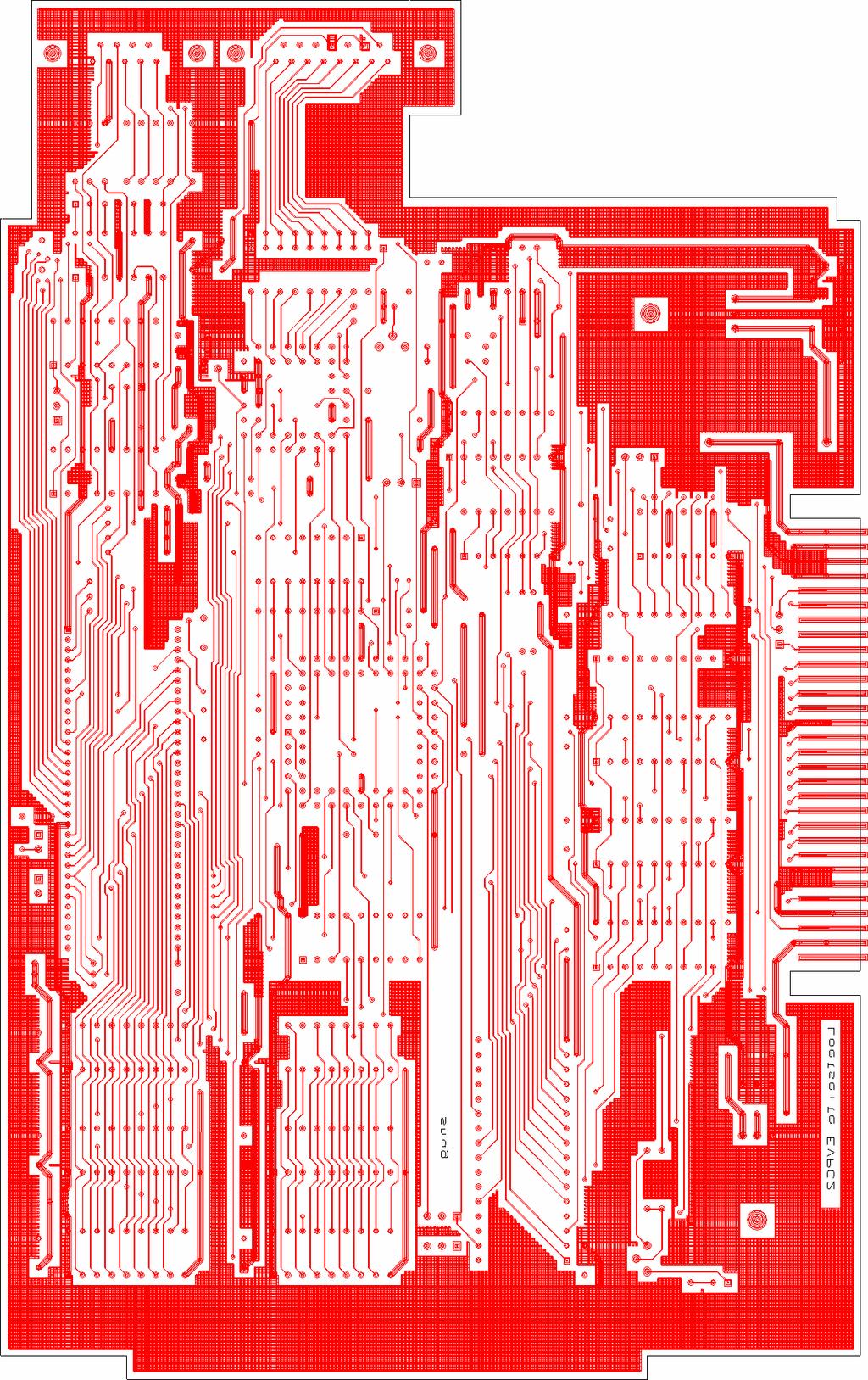
18 Layer
19 Drill Template
20 Schematic 1 (root)
21 Schematic 2 (Decoder and CRU Output)
22 Schematic 3 (Power supply)
23 Schematic 4 (output-multiplexer)
24 Schematic 5 (Enhanced Color Palette)
25 Schematic 6 (Flashrom/Eprom and NOVRAM)
26 Schematic 7 (Buss-Interface)
27 Schematic 8 (VDP, Video-RAM and Color buss)
28 Appendix C Pin-Assignment connector P2 Pin Name Description 1 GND Ground or Shield for sound 2 GND Ground or Shield for video 3 Red Analog RGB, red 4 Green Analog RGB, green 5 Blue Analog RGB, blue 6 Sound Sound output, analog 7 VCC +5 Volts 8 Sync Analog RGB, composite sync-signal 9 Mux Multiplexing for Pin 8, open or GND = Sync, +5V = FBAS How to connect a monitor to P2 The Output on connector P2 can support either analog monitors with RGB inputs or monitors with FBAS (also called composite-video ) input. See some examples below to connect a few common monitor types to your card (Phillips CM8802, CM8833 or 1084). Connect an analog RGB-Monitors with SCART (EURO-AV)-connector Pin Name Description SCART-Pin 1 GND Shield 21 2 GND Ground 4,5,9,13,18 3 Red Analog RGB, red 15 4 Green Analog RGB, green 11 5 Blue Analog RGB, blue 7 6 Sound Sound, analog 6, using 2-channel (CM8833 / 1084S) also SCART Not used, do not connect! 8 Sync Analog RGB, composite sync-signal Not used, do not connect! Connect an analog RGB-Monitors with Sub-Min-D9-connector Pin Name Description Monitor-Pin 1 GND Shield 1 2 GND Ground 2 3 Red Analog RGB, red 3 4 Green Analog RGB, green 4 5 Blue Analog RGB, blue 5 6 Sound Sound, analog Note: Must be wired externally. 7 VCC +5V Note: Monitor-Pin 6, if switching voltage needed. 8 Sync Analog RGB, composite sync-signal Not used, do not connect!
29 Connect an analog FBAS-Monitor with RCA (Cinch)-connector Pin Name Description RCA 1 GND Ground/Shield Shield FBAS-Jack (yellow) 2 GND Ground/Shield Shield Sound-Jack (white) 3 - Not used, do not connect! 4 - Not used, do not connect! 5 - Not used, do not connect! 6 Sound Sound, analog hot sound-jack (white) 7 VCC use resistor of Ohms connect to Pin 9 of P2 8 Sync Analog RGB, composite-video hot FBAS-Jack (yellow) 9 Mux as jumper wire! connect to Pin 7 vof P2 Note: modify DIP-switch on bare-board as described in DSR-manual!!! Available on V9938-cards only, V9958-cards do have RGB-output only! Pin-Assignment connector P1 (mouse/color-buss) Pin Name Description for V9938 for V C7 Color buss 2 C6 3 C5 4 C4 5 C3 6 C2 7 C1 8 C0 9 INT Interrupt-output 10 LPS/RDY LPS RDY 11 LPD/HRES LPD - 12 GND GND 13 SYCLK 447KHz output 14 GND GND 15 VCC +5V Note: V9958 will not support mouse/light-pen-interface (see Pin 10&11), color-buss only!!
30 Appendix D Technical Data connector P1 and P2 Analog RGB-Signals: 0,7Vpp/75Ω CVBS/FBAS (V9938 only): 1V +/- 0,5V/75Ω Video system: PAL/NTSC selected by software. Line-frequency : Hz fixed! Monitor must support this! For detailed information see technical Datasheet Yamaha V9938 or V9958! Sound: Digital Levels on P1: ca. 200mV/10KΩ TTL-Input, HC-MOS output
ONYX-MM-XT PC/104 Format Counter/Timer & Digital I/O Module
 ONYX-MM-XT PC/104 Format Counter/Timer & Digital I/O Module User Manual V1.4 Copyright 2009 Diamond Systems Corporation 1255 Terra Bella Avenue Mountain View, CA 94043 USA Tel (650) 810-2500 Fax (650)
SGCPU TI99/4P! Hardware Description. (Second-Generation-Central-Processing-Unit)...or otherwise:
...or otherwise:") (Second-Generation-Central-Processing-Unit)...or otherwise: TI99/4P! Hardware Description Last Manual Edit: 2017-10-17 Translation by Bob Carmany Actual versions at system-99 user-group Table of Contents
(Second-Generation-Central-Processing-Unit)...or otherwise: TI99/4P! Hardware Description Last Manual Edit: 2017-10-17 Translation by Bob Carmany Actual versions at system-99 user-group Table of Contents
CHAPTER Wi r i n g NOTICE:
 CHAPTER Wiring NOTICE: Information in this manual may change without notice. Midway Games West Inc. reserves the right to make improvements in equipment function, design, or components as progress in engineering
MMT-51/251 80C51/251 Microprocessor Board Rev. F HARDWARE / SOFTWARE USER'S REFERENCE MANUAL (c) 1996, 1999
 1996, 1999") MMT-51/251 80C51/251 Microprocessor Board Rev. F HARDWARE / SOFTWARE USER'S REFERENCE MANUAL (c) 1996, 1999 MIDWEST MICRO-TEK The information in this manual is subject to change without notice. Midwest
MMT-51/251 80C51/251 Microprocessor Board Rev. F HARDWARE / SOFTWARE USER'S REFERENCE MANUAL (c) 1996, 1999 MIDWEST MICRO-TEK The information in this manual is subject to change without notice. Midwest
University of Florida EEL 4744 Drs. Eric M. Schwartz, Karl Gugel & Tao Li Department of Electrical and Computer Engineering
 Page 1/9 Revision 1 OBJECTIVES In this document you will learn how to solder and to debug a board as you are building it. REQUIRED MATERIALS Website documents o UF 68HC12 Development Board Manual (board
Building and using JasperMIDI
 Building and using JasperMIDI Table of Contents Introduction... Bill Of Materials... 2 Building Choices... 3 Construction... 4 Installing in a Jasper enclosure... 5 Standalone use... 6 Using JasperMIDI...
CHAPTER TWELVE - Memory Devices
 CHAPTER TWELVE - Memory Devices 12.1 6x1,024 = 16,384 words; 32 bits/word; 16,384x32 = 524,288 cells 12.2 16,384 addresses; one per word. 12.3 2 16 = 65,536 words = 64K. Thus, memory capacity is 64Kx4.
PAS 9737/AI-SMT ENGINEERING SPECIFICATION
 Document PAS54 Spec Revision C (7/3/8) PAS 9737/AI-SMT ENGINEERING SPECIFICATION 64 CHANNEL, 6 BIT VME ANALOG INPUT CARD PCB Revision D (7/3/8) Additional copies of this manual or other Precision Analog
Technical Information Manual
 Technical Information Manual Revision n. 3 28 August 2002 MOD. V550 / V550 B MOD. V550 A / V550 AB 2 CHANNEL C-RAMS CAEN will repair or replace any product within the guarantee period if the Guarantor
Pmod I2S2 Reference Manual
 Pmod I2S2 Reference Manual The Digilent Pmod I2S2 (Revision A) features a Cirrus CS5343 Multi Bit Audio A/D Converter and a Cirrus CS4344 Stereo D/A Converter, each connected to one of two audio jacks.
MB68k-100 Motherboard Test Procedure, C
 MB68k-100 Motherboard Test Procedure, C Set Up Instructions:! DC power supply! Obtain 2 solid core jumper wires for testing o 1 length for pull-up wire, installing one end in A1CON161, pos 61 o 2 length
2. (2 pts) If an external clock is used, which pin of the 8051 should it be connected to?
 If an external clock is used, which pin of the 8051 should it be connected to?") ECE3710 Exam 2. Name _ Spring 2013. 5 pages. 102 points, but scored out of 100. You may use any non-living resource to complete this exam. Any hint of cheating will result in a 0. Part 1 Short Answer 1.
ECE3710 Exam 2. Name _ Spring 2013. 5 pages. 102 points, but scored out of 100. You may use any non-living resource to complete this exam. Any hint of cheating will result in a 0. Part 1 Short Answer 1.
References GESMEM-12D: Universal memory module, not equipped
 GESMEM-D MEMORY Revision.0 UNIVERSAL EPROM / RAM / EEPROM MEMORY MODULE UP TO MBYTES The GESMEM-D module is equipped with twelve -pin JEDEC sockets which accept memory devices from Kbits up to Mbits. The
KNJN I2C bus development boards
 KNJN I2C bus development boards 2005, 2006, 2007, 2008 KNJN LLC http://www.knjn.com/ Document last revision on December 5, 2008 R22 KNJN I2C bus development boards Page 1 Table of Contents 1 The I2C bus...4
USB-4303 Specifications
 Specifications Document Revision 1.0, February, 2010 Copyright 2010, Measurement Computing Corporation Typical for 25 C unless otherwise specified. Specifications in italic text are guaranteed by design.
Analog Current Input - 16 Channel IC693ALG223. Current Ranges. Power Requirements and LEDs. Location in System. Analog Input Modules
 Analog Input Modules Analog Current Input - 16 Channel IC693ALG223 The 16-Channel Analog Current Input module provides up to 16 single-ended input channels, each capable of converting an analog input signal
PVK40. User's manual. Feature Rich Development and Educational Kit for 40-pin Microchip PIC microcontrollers
 PVK40 User's manual Feature Rich Development and Educational Kit for 40-pin Microchip PIC microcontrollers CONTENTS PVK40 3 On-board peripherals: 3 Power supply 4 Microcontroller 4 Reset circuitry 4 Oscilator
FUNCTION. AVDD Port1. I/O Buffer AVDD AK4254
 [AKD-A]. AKD-A AK Evaluation Board Rev. GENERAL DESCRIPTION AKD-A is an evaluation board for AK that has : video switches. This board can achieve the interface with video systems via RCA connectors. Ordering
AIAO U CompactPCI Analog I/O Card. User Manual. 13 Altalef St. Yehud, Israel Tel: 972 (3) Fax: 972 (3)
 Fax: 972 (3)") AIAO-0700 3U CompactPCI Analog I/O Card User Manual 13 Altalef St. Yehud, Israel 56216 Tel: 972 (3) 632-0533 Fax: 972 (3) 632-0458 www.tenta.com 919 Kifer Road Sunnyvale, CA 94086 USA Tel: (408) 328-1370
AIAO-0700 3U CompactPCI Analog I/O Card User Manual 13 Altalef St. Yehud, Israel 56216 Tel: 972 (3) 632-0533 Fax: 972 (3) 632-0458 www.tenta.com 919 Kifer Road Sunnyvale, CA 94086 USA Tel: (408) 328-1370
CANopen Unit CANit-20
 General Description The CANit-20 is a low cost CANopen Unit with 16 digital inputs and 16 digital outputs suitable for DC 24 V. The I/O s are positive switching and optoisolated from the bus and the system
RPG 100 EVALUATION BOARD RPG100-TB(MB) User's manual
 User's manual") HM-RAE102-0312 RPG 100 EVALUATION BOARD RPG100-TB(MB) User's manual REV. 02 26/09/2003 revised http://www.fdk.co.jp Contents 1. RPG100 Evaluation Board composition Models: RPG100-TB and RPG100-MB 2. Descriptions
HM-RAE102-0312 RPG 100 EVALUATION BOARD RPG100-TB(MB) User's manual REV. 02 26/09/2003 revised http://www.fdk.co.jp Contents 1. RPG100 Evaluation Board composition Models: RPG100-TB and RPG100-MB 2. Descriptions
Carrier Board Socket Modem CAB/MOD1
 Carrier Board Socket Modem CAB/MOD1 User Manual Content 1 INTRODUCTION...3 1.1 Conventions used in this Document...3 1.2 Checklist...4 1.3 Main Features...5 2 BOARD LAYOUT...6 3 BOARD COMPONENTS...7 3.1
ACR8020 Hardware Manual
 p/n YPM08126 Automation ACR8020 Hardware Manual Effective: October 7, 2002 This page intentionally left blank. CHANGE NOTICE ACR8020 Hardware Manual P/N PM08126 Version Change: From: Version 1.00, Dated
CMS-8GP32. A Motorola MC68HC908GP32 Microcontroller Board. xiom anufacturing
 CMS-8GP32 A Motorola MC68HC908GP32 Microcontroller Board xiom anufacturing 2000 717 Lingco Dr., Suite 209 Richardson, TX 75081 (972) 994-9676 FAX (972) 994-9170 email: Gary@axman.com web: http://www.axman.com
Arduino Uno. Arduino Uno R3 Front. Arduino Uno R2 Front
 Arduino Uno Arduino Uno R3 Front Arduino Uno R2 Front Arduino Uno SMD Arduino Uno R3 Back Arduino Uno Front Arduino Uno Back Overview The Arduino Uno is a microcontroller board based on the ATmega328 (datasheet).
1%$6+2:7,0(*2/'(',7,21 1)/%/,7=*2/'(',7,21 &219(56,21.,7
/%/,7=*2/'(',7,21 &219(56,21.,7") 1%$6+2:7,0(*2/'(',7,21 1)/%/,7=*2/'(',7,21 &219(56,21.,7 C H A P T E R F I V E WIRING WARNING: Failure to reconnect ground wires or replace metal shields may result in radio frequency interference. NOTICE:
1%$6+2:7,0(*2/'(',7,21 1)/%/,7=*2/'(',7,21 &219(56,21.,7 C H A P T E R F I V E WIRING WARNING: Failure to reconnect ground wires or replace metal shields may result in radio frequency interference. NOTICE:
VLSI AppNote: VSx053 Simple DSP Board
 : VSx053 Simple DSP Board Description This document describes the VS1053 / VS8053 Simple DPS Board and the VSx053 Simple DSP Host Board. Schematics, layouts and pinouts of both cards are included. The
Evaluates: DS28E80. DS28E80 Evaluation System. General Description. Benefits and Features. EV Kit Contents
 General Description The DS28E80 evaluation system (EV system) consists of a single evaluation kit (EV kit) that includes a package of five DS28E80 devices in a 6-pin TDFN package, a DS9120Q+ socket board
U C H L T. DSP-Board C32F. Features for DSP Board C32F
 HOLE35 RS232 9600 BOD RS232 DSUB9M CONNECTOR 2X32 TI DSP LINK 10 MBOD HOLE35 R U C H DSP-Board C32F L T D (C) RUCH SYSTEM LTD., 1998. DSP SERVOCONTROLLER BOARD FOR EUROBUS. RS422R PAL EPROM 64K8-12V +12V
Goal: We want to build an autonomous vehicle (robot)
") Goal: We want to build an autonomous vehicle (robot) This means it will have to think for itself, its going to need a brain Our robot s brain will be a tiny computer called a microcontroller Specifically
Goal: We want to build an autonomous vehicle (robot) This means it will have to think for itself, its going to need a brain Our robot s brain will be a tiny computer called a microcontroller Specifically
PAS 9732/AI ENGINEERING SPECIFICATION
 Document PAS010 Revision C 8/27/03 PAS 9732/AI ENGINEERING SPECIFICATION 8 CHANNEL, 14 BIT, 3 MHz per CHANNEL VME ANALOG INPUT CARD Revision A (11/18/2000) Additional copies of this manual or other Precision

PCI to SH-3 AN Hitachi SH3 to PCI bus
 PCI to SH-3 AN Hitachi SH3 to PCI bus Version 1.0 Application Note FEATURES GENERAL DESCRIPTION Complete Application Note for designing a PCI adapter or embedded system based on the Hitachi SH-3 including:
TMC428 Evaluation Kit V2.0 Manual English
 TMC428 Evaluation Kit V2.0 Manual English Version: 2.01 July 30 th, 2002 2 TMC428 Evaluation Kit V2.01 Version Version Date Author Remarks 2.00 2002-07-29 OK Created from version 1.02 2.01 2002-07-30 OK
RapID Platform Network Interface Module Datasheet June 4, 2012
 RapID Platform Network Interface Module Datasheet 1 support@innovasic.com Copyright 2012 by Innovasic, Inc. Published by Innovasic, Inc. 5635 Jefferson St. NE, Suite A, Albuquerque, New Mexico 87109 USA
Owner s Hardware Service Manual Frank Control Computer System
 Owner s Hardware Service Manual Frank Control Computer System Revision 0105 ABOUT THIS MANUAL This section describes the contents of this manual and how to use this manual effectively. It was designed
ARDUINO MICRO WITHOUT HEADERS Code: A000093
 ARDUINO MICRO WITHOUT HEADERS Code: A000093 Arduino Micro is the smallest board of the family, easy to integrate it in everyday objects to make them interactive. The Micro is based on the ATmega32U4 microcontroller
CDN502 HIGH DENSITY I/O ADAPTER USER GUIDE
 CDN502 HIGH DENSITY I/O ADAPTER USER GUIDE 13050201 (c) Copyright DIP Inc., 1996 DIP Inc. P.O. Box 9550 MORENO VALLEY, CA 92303 714-924-1730 CONTENTS DN502 PRODUCT OVERVIEW 1 DN502 INSTALLATION 1 POWER
Lab3: I/O Port Expansion
 Page 1/6 Revision 0 26-Jan-16 OBJECTIVES Explore and understand the implementation of memory-mapped I/O. Add an 8-bit input port and an 8-bit output port. REQUIRED MATERIALS EEL 3744 (upad and upad Proto
PAS 9796/DIO ENGINEERING SPECIFICATION
 Document PAS018 DOC Revision C1 10/14/2009 PAS 9796/DIO ENGINEERING SPECIFICATION 160 CHANNEL VME DIGITAL INPUT / OUTPUT CARD Additional copies of this manual or other Precision Analog Systems (PAS) literature
ARDUINO LEONARDO WITH HEADERS Code: A000057
 ARDUINO LEONARDO WITH HEADERS Code: A000057 Similar to an Arduino UNO, can be recognized by computer as a mouse or keyboard. The Arduino Leonardo is a microcontroller board based on the ATmega32u4 (datasheet).
DEVBOARD3 DATASHEET. 10Mbits Ethernet & SD card Development Board PIC18F67J60 MICROCHIP
 DEVBOARD3 DATASHEET 10Mbits Ethernet & SD card PIC18F67J60 MICROCHIP Version 1.0 - March 2009 DEVBOARD3 Version 1.0 March 2009 Page 1 of 7 The DEVBOARD3 is a proto-typing board used to quickly and easily
AKD4220-A AK4220 Evaluation Board Rev.0
 AKD4220-A AK4220 Evaluation Board Rev.0 GENERAL DESCRIPTION AKD4220-A is an evaluation board for AK4220 that has various 7:3 audio and 6:3 video switches. This board can achieve the interface with AV systems
AN-HK-32. In-Circuit Programming of FLASH Memory in the MC68HC908GP32. nc... Freescale Semiconductor, I. PART 1 Introduction
 Order this document by AN-HK-32/H Rev. 2.0 AN-HK-32 In-Circuit Programming of FLASH Memory in the MC68HC908GP32 By T.C. Lun Applications Engineering Microcontroller Division Hong Kong PART 1 Introduction
UMBC. Select. Read. Write. Output/Input-output connection. 1 (Feb. 25, 2002) Four commonly used memories: Address connection ... Dynamic RAM (DRAM)
 Four commonly used memories: Address connection ... Dynamic RAM (DRAM)") Memory Types Two basic types: ROM: Read-only memory RAM: Read-Write memory Four commonly used memories: ROM Flash (EEPROM) Static RAM (SRAM) Dynamic RAM (DRAM) Generic pin configuration: Address connection
Memory Types Two basic types: ROM: Read-only memory RAM: Read-Write memory Four commonly used memories: ROM Flash (EEPROM) Static RAM (SRAM) Dynamic RAM (DRAM) Generic pin configuration: Address connection
3. The MC6802 MICROPROCESSOR
 3. The MC6802 MICROPROCESSOR This chapter provides hardware detail on the Motorola MC6802 microprocessor to enable the reader to use of this microprocessor. It is important to learn the operation and interfacing
8051 Microcontroller
 8051 Microcontroller The 8051, Motorola and PIC families are the 3 leading sellers in the microcontroller market. The 8051 microcontroller was originally developed by Intel in the late 1970 s. Today many
CEIBO FE-5111 Development System
 CEIBO FE-5111 Development System Development System for Atmel W&M T89C5111 Microcontrollers FEATURES Emulates Atmel W&M T89C5111 4K Code Memory Real-Time Emulation and Trace Frequency up to 33MHz/5V ISP
Nistune Type 1 Diagnostics Technical Notes V1.2 (JECS ECCS Legacy Engine Control Units)
") Nistune Type 1 Diagnostics Technical Notes V1.2 (JECS ECCS 1984-1989 Legacy Engine Control Units) Copyright 2004, 2005, 2006, 2014 Nistune Developments WARNING If your ECU pulses the fuel pump, injectors,
Nistune Type 1 Diagnostics Technical Notes V1.2 (JECS ECCS 1984-1989 Legacy Engine Control Units) Copyright 2004, 2005, 2006, 2014 Nistune Developments WARNING If your ECU pulses the fuel pump, injectors,
8051 INTERFACING TO EXTERNAL MEMORY
 8051 INTERFACING TO EXTERNAL MEMORY Memory Capacity The number of bits that a semiconductor memory chip can store Called chip capacity It can be in units of Kbits (kilobits), Mbits (megabits), and so on
DEMO9S08SH32/SG32 Demonstration Board for Freescale MC9S08SH32/SG32
 DOC-0421-010, REV A DEMO9S08SH32/SG32 Demonstration Board for Freescale MC9S08SH32/SG32 Axiom Manufacturing 2813 Industrial Lane Garland, TX 75041 Email: Sales@axman.com Web: http://www.axman.com CONTENTS
RapID Platform DLR Network Interface Module Datasheet January 9, 2013
 RapID Platform DLR Network Interface Module Datasheet 1 support@innovasic.com Copyright 2013 by Innovasic, Inc. Published by Innovasic, Inc. 5635 Jefferson St. NE, Suite A, Albuquerque, New Mexico 87109
F2MC MB90385 series Evaluation Board Documentation. Revision Date Comment V New document
 F2MC MB90385 series Evaluation Board Documentation Revision Date Comment V1.0 08.25.02 New document 1 Warranty and Disclaimer To the maximum extent permitted by applicable law, Fujitsu Microelectronics
DIGITAL COMPASS SOLUTION
 Features 5 Heading Accuracy, 0.5 Resolution 2-axis Capability Small Size (19mm x 19mm x 4.5mm), Light Weight Advanced Hard Iron Calibration Routine for Stray Fields and Ferrous Objects 0 to 70 C Operating
MOTENC-Lite 4-Axis PCI Motion & I/O Control Board. Reference Manual Rev 1.1, June 20, Copyright 2005 VITAL Systems Inc
 MOTENC-Lite 4-Axis PCI Motion & I/O Control Board Reference Manual Rev 1.1, June 20, 2005 Copyright 2005 VITAL Systems Inc www.vitalsystem.com This Page Intentionally Left Blank Table of Contents 1. OVERVIEW...
BlueTooth Carrier Board CAB/BT1
 BlueTooth Carrier Board CAB/BT1 User Manual Content 1 INTRODUCTION...4 1.1 Conventions used in this Document...4 1.2 Checklist...5 1.3 Main Features...6 2 BOARD LAYOUT...7 3 BOARD COMPONENTS...8 3.1 Reset
Mega128-DEVelopment Board Progressive Resources LLC 4105 Vincennes Road Indianapolis, IN (317) (317) FAX
 (317) FAX") Mega128-DEVelopment Board Progressive Resources LLC 4105 Vincennes Road Indianapolis, IN 46268 (317) 471-1577 (317) 471-1580 FAX http://www.prllc.com GENERAL The Mega128-Development board is designed for
Mega128-DEVelopment Board Progressive Resources LLC 4105 Vincennes Road Indianapolis, IN 46268 (317) 471-1577 (317) 471-1580 FAX http://www.prllc.com GENERAL The Mega128-Development board is designed for
SAB-QS Quick Start November 9, SAB-QS Quick Start SAB-QS TRANSDUCERS 1 X4. Figure 1: SAB-QS Connector and Jumper Placement
 SAB-QS Quick Start November, 000 SAB-QS Quick Start This document aims to provide a systematic setup procedure to enable you to setup and use your SAB-QS as easily as possible. This guide will concentrate
Test ROM for Zaccaria 1B1165 CPU Board
 Introduction Test ROM for Zaccaria 1B1165 CPU Board Version 1.2 13 June 2008 David Gersic http://www.zaccaria pinball.com One of the challenges to working on an unknown CPU board is that Zaccaria's software
Rapid40i PIC Prototyping PCB User Manual
 Description This is a PCB designed to facilitate the rapid prototyping of a device based on a 40 pin Microchip PIC microcontroller. To allow users to focus on their application, we take care of key housekeeping
OPERATIONAL UP TO. 300 c. Microcontrollers Memories Logic
 OPERATIONAL UP TO 300 c Microcontrollers Memories Logic Whether You Need an ASIC, Mixed Signal, Processor, or Peripheral, Tekmos is Your Source for High Temperature Electronics Using either a bulk silicon
keyestudio Keyestudio MEGA 2560 R3 Board
 Keyestudio MEGA 2560 R3 Board Introduction: Keyestudio Mega 2560 R3 is a microcontroller board based on the ATMEGA2560-16AU, fully compatible with ARDUINO MEGA 2560 REV3. It has 54 digital input/output
Address connections Data connections Selection connections
 Interface (cont..) We have four common types of memory: Read only memory ( ROM ) Flash memory ( EEPROM ) Static Random access memory ( SARAM ) Dynamic Random access memory ( DRAM ). Pin connections common
The pin details are given below: V cc, GND = +5V and Ground A 11 -A 0 = address lines. Fig.2.19 Intel 2716 Read Only Memory
 Lecture-8 Typical Memory Chips: In previous lecture, the different types of static memories were discussed. All these memories are random access memories. Any memory location can be accessed in a random
PmodJSTK2 Reference Manual. Overview. 1 Functional Descriptions. Revised July 19, 2016 This manual applies to the PmodJSTK2 rev. C
 1300 Henley Court Pullman, WA 99163 509.334.6306 www.digilentinc.com PmodJSTK2 Reference Manual Revised July 19, 2016 This manual applies to the PmodJSTK2 rev. C Overview The Digilent PmodJSTK2 (Revision
CAN EGT-8 Amplifier. About:
 CAN EGT-8 Amplifier About: 1. The amplifier supports up to eight K-Type temperature probes. 2. EGT temperatures are sent to engine management ECU via CAN Bus. 3. One volt input that can be used to send
Microprocessors/Microcontrollers
 Microprocessors/Microcontrollers A central processing unit (CPU) fabricated on one or more chips, containing the basic arithmetic, logic, and control elements of a computer that are required for processing
MicroBolt. Microcomputer/Controller Featuring the Philips LPC2106 FEATURES
 Microcomputer/Controller Featuring the Philips LPC2106 FEATURES Powerful 60 MHz, 32-bit ARM processing core. Pin compatible with 24 pin Stamp-like controllers. Small size complete computer/controller with
ARDUINO MEGA 2560 REV3 Code: A000067
 ARDUINO MEGA 2560 REV3 Code: A000067 The MEGA 2560 is designed for more complex projects. With 54 digital I/O pins, 16 analog inputs and a larger space for your sketch it is the recommended board for 3D
Arduino ADK Rev.3 Board A000069
 Arduino ADK Rev.3 Board A000069 Overview The Arduino ADK is a microcontroller board based on the ATmega2560 (datasheet). It has a USB host interface to connect with Android based phones, based on the MAX3421e
PCI-1751U. 48-bit Digital Input/Output Card with Universal PCI Bus. User Manual
 PCI-1751U 48-bit Digital Input/Output Card with Universal PCI Bus User Manual Copyright This documentation and the software included with this product are copyrighted 2006 by Advantech Co., Ltd. All rights
_ V Intel 8085 Family In-Circuit Emulation. Contents. Technical Notes
 _ V9.12. 225 Technical Notes Intel 8085 Family In-Circuit Emulation This document is intended to be used together with the CPU reference manual provided by the silicon vendor. This document assumes knowledge
ARDUINO LEONARDO ETH Code: A000022
 ARDUINO LEONARDO ETH Code: A000022 All the fun of a Leonardo, plus an Ethernet port to extend your project to the IoT world. You can control sensors and actuators via the internet as a client or server.
GPIO-MM User Manual. FPGA-based PC/104 Counter/Timer and Digital I/O Module. User Manual v1.0 Personality 0x22
 GPIO-MM User Manual FPGA-based PC/104 Counter/Timer and Digital I/O Module User Manual v1.0 Personality 0x22 Copyright 2006 1255 Terra Bella Ave. Mountain View, CA 94043 Tel (650) 810-2500 Fax (650) 810-2525
ARDUINO UNO REV3 Code: A000066
 ARDUINO UNO REV3 Code: A000066 The UNO is the best board to get started with electronics and coding. If this is your first experience tinkering with the platform, the UNO is the most robust board you can
T P G. Test Pattern Generator. Updated 7/12/ Firmware 03 (C) 2017 CraftyMech LLC.
 2017 CraftyMech LLC.") T P G Test Pattern Generator Updated 7/12/2017 - Firmware 03 (C) 2017 CraftyMech LLC http://craftymech.com Usage The Test Pattern Generator produces display patterns for use with Standard Resolution (15.7khz)
T P G Test Pattern Generator Updated 7/12/2017 - Firmware 03 (C) 2017 CraftyMech LLC http://craftymech.com Usage The Test Pattern Generator produces display patterns for use with Standard Resolution (15.7khz)
Manual iaq-engine Indoor Air Quality sensor
 Manual iaq-engine, Version 2.0 May 2011 (all data subject to change without notice) Manual iaq-engine Indoor Air Quality sensor Digital and analog I/O SMD type package Product summary iaq-engine is used
Product Specification for SAB-S-MODBUS
 SAB-S-MODBUS May 9, 2011 Product Specification for SAB-S-MODBUS The SAB-S-MODBUS is a two-channel module that measures single or multiple magnet transducer position and returns this information to a host
MICROCONTROLLER AND PLC LAB-436 SEMESTER-5
 MICROCONTROLLER AND PLC LAB-436 SEMESTER-5 Exp:1 STUDY OF MICROCONTROLLER 8051 To study the microcontroller and familiarize the 8051microcontroller kit Theory:- A Microcontroller consists of a powerful
TIP815. ARCNET Controller. Version 1.0. User Manual. Issue September 2009
 The Embedded I/O Company TIP815 ARCNET Controller Version 1.0 User Manual Issue 1.0.7 September 2009 TEWS TECHNOLOGIES GmbH Am Bahnhof 7 25469 Halstenbek, Germany Phone: +49 (0) 4101 4058 0 Fax: +49 (0)
GE Fanuc IC694ALG221. Rx3i PacSystem
 GE Fanuc IC694ALG221 http://www.pdfsupply.com/automation/ge-fanuc/rx3i-pacsystem/ic694alg221 Rx3i PacSystem Input module, analog 4 point current. IC694A IC694AL IC694ALG 919-535-3180 sales@pdfsupply.com
DS1870 LDMOS BIAS CONTROLLER EV KIT
 GENERAL DESCRIPTION The DS1870 EV Kit provides hardware and Window s compatible software to simplify the evaluation of the DS1870 LDMOS Bias Controller. FEATURES Includes test socket for solderless connectivity
E3940 Microprocessor Systems Laboratory. Introduction to the Z80
 E3940 Microprocessor Systems Laboratory Introduction to the Z80 Andrew T. Campbell comet.columbia.edu/~campbell campbell@comet.columbia.edu E3940 Microprocessor Systems Laboratory Page 1 Z80 Laboratory
Sidewinder Development Board rev 1.0
 33 Sidewinder Development Board rev 1.0 Features Altera MAX V CPLD 5M160ZT100C5 JTAG programmable USB programmable USB powered 12 On board LEDs 10 on board switches 3 RGB LEDs One 40 pin expansion headers
H89-Z37 DOUBLE-DENSITY FLOPPY CONTROLLER
 H8-Z37 DOUBLE DENSITY FLOPPY CONTROLLER 2015 H89-Z37 DOUBLE-DENSITY FLOPPY CONTROLLER Norberto Collado norby@koyado.com 6/6/2015 Revision History and Disclaimer Revision History Revision Date Comments
WIRING & CIRCUIT INFORMATION
 2))52$' 7+81'(5TM &+$37(5 WIRING & CIRCUIT INFORMATION WARNING: Failure to reconnect ground wires or replace metal shields may result in radio frequency interference. NOTICE: The term VGM refers to the
Lab 16: Data Busses, Tri-State Outputs and Memory
 Lab 16: Data Busses, Tri-State Outputs and Memory UC Davis Physics 116B Rev. 0.9, Feb. 2006 1 Introduction 1.1 Data busses Data busses are ubiquitous in systems which must communicate digital data. Examples
TUG Combo Board
 TUG Combo Board Overview These notes supplement the Combo Board Manual providing a functional overview of the description and operation of the board. (Note: This Version does not yet fully cover the 6116
Evaluation Board for 14-/16-Bit, Serial Input, VOUT NanoDACs EVAL-AD5040EB/EVAL-AD506xEB
 Evaluation Board for 14-/16-Bit, Serial Input, VOUT NanoDACs EVAL-AD5040EB/EVAL-AD506xEB FEATURES Full-featured evaluation board for the AD5040/AD506x Operates from single 2.7 V to 5.5 V supplies On-board
Slick Line Acquisition System Manual
 SCIENTIFIC DATA SYSTEMS, INC. SLICK LINE ACQUISITION BOX Slick Line Acquisition System Manual This document contains proprietary information. Copyright 2005 Scientific Data Systems, Inc. All rights reserved.
Homework 5: Circuit Design and Theory of Operation Due: Friday, February 24, at NOON
 Homework 5: Circuit Design and Theory of Operation Due: Friday, February 24, at NOON Team Code Name: Motion Tracking Laser Platform Group No.: 9 Team Member Completing This Homework: David Kristof NOTE:
EB-51 Low-Cost Emulator
 EB-51 Low-Cost Emulator Development Tool for 80C51 Microcontrollers FEATURES Emulates 80C51 Microcontrollers and Derivatives Real-Time Operation up to 40 MHz 3.3V or 5V Voltage Operation Source-Level Debugger
M68HC705L4 PROGRAMMER BOARD APPLICATION NOTE
 M68HC705L4PGMR JUNE 1992 M68HC705L4 PROGRAMMER BOARD (REVision A PWBs only) APPLICATION NOTE INTRODUCTION This application note describes the programming technique used to program and verify the XC68HC705L4
Display Real Time Clock (RTC) On LCD. Version 1.2. Aug Cytron Technologies Sdn. Bhd.
 On LCD. Version 1.2. Aug Cytron Technologies Sdn. Bhd.") Display Real Time Clock (RTC) On LCD PR12 Version 1.2 Aug 2008 Cytron Technologies Sdn. Bhd. Information contained in this publication regarding device applications and the like is intended through suggestion
Display Real Time Clock (RTC) On LCD PR12 Version 1.2 Aug 2008 Cytron Technologies Sdn. Bhd. Information contained in this publication regarding device applications and the like is intended through suggestion
Microcontroller Systems. ELET 3232 Topic 11: General Memory Interfacing
 Microcontroller Systems ELET 3232 Topic 11: General Memory Interfacing 1 Objectives To become familiar with the concepts of memory expansion and the data and address bus To design embedded systems circuits
Issue : 1.1 Date : 19/1/2004. Trigger IO. C-Cam Technologies. a division of. Vector International 1 / 6
 Trigger IO C-Cam Technologies a division of Vector International 1 / 6 1 Trigger IO connector Trigger IO connector Camera with LS interface Trigger IO connector Camera with USB interface 2 / 6 1.1 Pin
CDN503 HIGH DENSITY I/O ADAPTER USER GUIDE
 CDN503 HIGH DENSITY I/O ADAPTER USER GUIDE 13050301 (c) Copyright DIP Inc., 1996 DIP Inc. P.O. Box 9550 MORENO VALLEY, CA 92303 714-924-1730 CONTENTS DN503 PRODUCT OVERVIEW 1 DN503 INSTALLATION 1 POWER
This connector has been added along with the signals needed by the REEL SAFE system
 MODIFICATION TO AMS4A046 PANEL Modification adds the following three features: 1. CCL Detector and depth display The panel will now detect and display the depth where a collar was detected. The CCL signal
eip-10 Embedded TCP/IP 10-BaseT Network Module Features Description Applications
 Embedded TCP/IP 10-BaseT Network Module Features 8-bit reprogrammable Microcontroller with Enhanced Flash program memory, EEPROM and Static RAM data memory On board 10Mbps Ethernet controller, and RJ45
CPU369-Module Documentation. Fujitsu Microelectronics Europe GmbH Am Siebenstein Dreieich-Buchschlag, Germany
 CPU369-Module Documentation Fujitsu Microelectronics Europe GmbH Am Siebenstein 6-10 63303 Dreieich-Buchschlag, Germany History Revision Date Comment V1.0 08.03.01 New Document V1.1 17.10.03 Modifications