1. The card is inserted on the mainboard without CPU, or the CPU is not running. 2. When the RST LED is lit up (the tested mainboard is resetting).
|
|
|
- Christina Terry
- 6 years ago
- Views:
Transcription
1
2 Improvement Note As the 2-bit code cards diagnose the mainboard by BIOS (refer to the SYNOPSIS in chapter 1), the code should not be displayed in such following cases 1. The card is inserted on the mainboard without CPU, or the CPU is not running. 2. When the RST LED is lit up (the tested mainboard is resetting). In any case above, the card and LED doesn t light up or light up briefly; rule out the original code. If the code is not displayed beside cases above, the card is not compatible with the mainboard which is being tested. You just need a more advanced post card like PI0050.
3 CONTENT 1.Synopsis (1) 2.Obligatory content (1) 3.Hexadecimal character table (2) 4.Description of LED displays (2) 5.Flow chart (3) 6.Error code table (4) 7.Description of beep code (24) (1) BIOS beep codes (fatal error) (24) (2) BIOS beep codes (Non-fatal error). (24) (3) BIOS beep codes (24) (4) Phoenix BIOS beep codes (25) (5) IBM BIOS beep codes (27) 8.Corrective Action (27) (1) If I forget the password,what can I do? (27) ① Omnipotent password (27) Ⅰ. password (27) Ⅱ. password (28) Ⅲ. Others (28) ② Discharge by software (28) ③ Hardware jumper discharge to CMOS BIOS (29) ④ Get help from your dealer (2).How to enter CMOS SETUP? (29) (29) 9.If the code is not included in the book,what can I do? (30) 10.Answers of frequently- asked questions (30) Introduce of run LEDS (31)
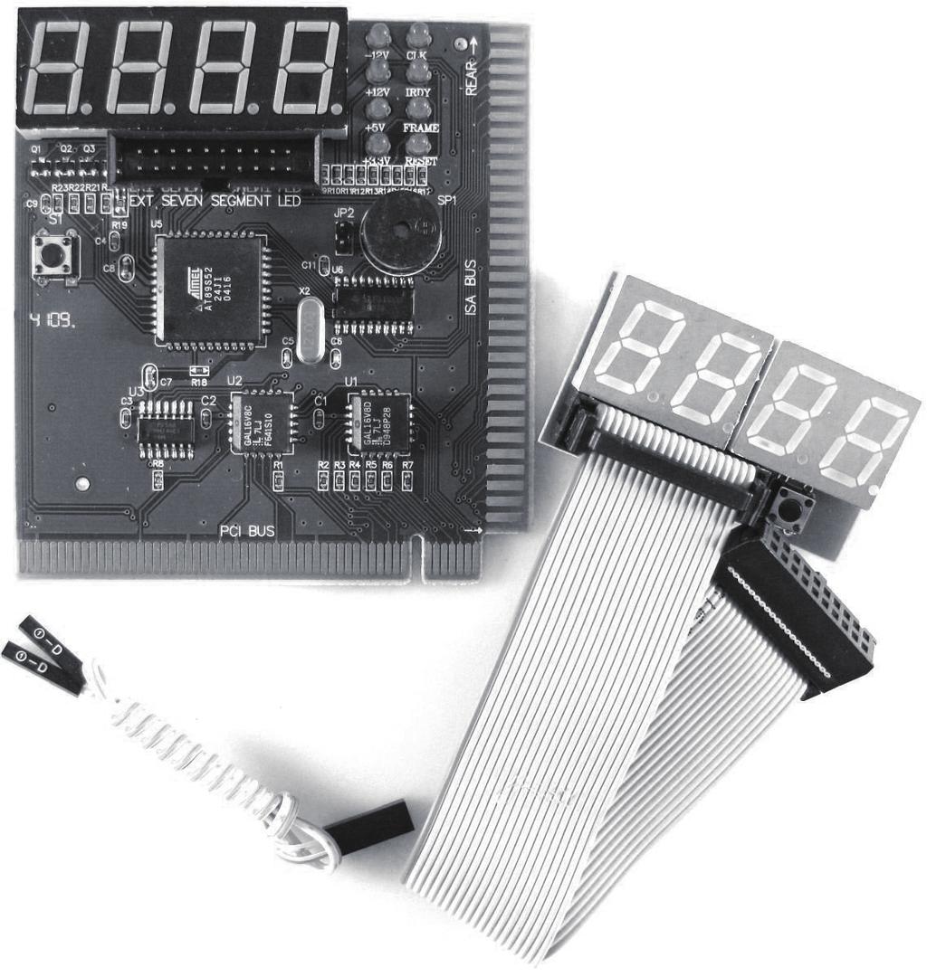
4 1.SYNOPSIS The card is named POST (Power On Self Test ) card too. It could display error code by the result of POST. Then you would soon determine the error in code table. Especially when the PC can t boot operating system, blank screen or the card and motherboard couldn t issue an audible beep. It is a powerful diagnostic tool. Now just use it. You ll get the result twice with half the effort. When the power is turned on, the BIOS would have a strict test with system circuit, memorizer, keyboard video hard disc and floppy drive. Then it would analyze the system configuration, initializing the basic I/O setup that already configured. Next, boot the operating system. By the trait of the card, you can determine the error easily like this. If the error occurs during the test of pivotal parts, it will halt the work and nothing appears on the screen. If the pivotal parts is OK, you can test the parts that s unimportant, this may not halt the work even if any error occurs. And the system reports an error message at the same time. Now when the computer goes wrong, especially the fateful error, and there is nothing appears on the screen, you can insert the card into the expansion slot. Refer to the error code table and the trouble is clear. 2.OBLIGATORY CONTENT ① The error code table is in the order of the code value that from small to big. The sequence that the code displays is decided by BIOS of the motherboard. ② that hasn t been defined is not included in table. ③ For the different BIOS (such as,, Phoenix), a code has different meanings. Refer to the user s guide, or see it on the BIOS IC on the motherboard. ④ There is only some codes displayed when you insert the card into the PCI slot on a few motherboards, but when it is plugged into the ISA slot, all the codes will be displayed. At present, it has been discovered that code is displayed when you insert the card into the PCI slot of several computers which has registered trade mark, but not ISA. So you d better try it on the other slot if the code is not displayed. In addition, on the different PCI slots of a board, some can display the code, for example, the code is displayed and goes from 00 to FF when you insert the card into the PCL slot, which is near the CPU on motherboard DELL810, but if in the other slot, the code would stop at the port 38. ⑤ The time that reset message output needed is not always in phase, so sometimes the code is displayed when in the card in the ISA, but it is stopped at the original code when in the PCI. ⑥ As there are more and more kinds motherboards, and the code of BIOS POST is updated ceaselessly, so the meanings of error codes are just for reference. 1
5 ⑦ According to experience: 2-bits code card is available in testing mainboard below Pil300, but not available in mainboard above Pil300, so it s better to buy 4-bits Pi0050 card. Furthermore, we haven t received any undesirable feedback from our buyer. 3. Hexadecimal character table. Decimalist Hexadecimal The POST card display A 11 B 12 C 13 D 14 E 15 F A B C D E F 4.Description of LED displays LED Type RUN Bus pulse CLK Bus clock IRDY Basic input/ output read Manager is ready OSC oscillation FRAME Frame periods RST Reset BIOS 12V Power -12V 5V -5V Power Power Power 3V3 Power Description If the LED lights, the mainboard has worked, no matter if the code changes. Lights when the power is applied to the empty board (even without CPU),or else there is no message. LED that turns on and off when the board is powered on, as CPU is reading to BIOS. LED that turns on and off when there is a message. Lights when the board is powered on, or else the crystal oscillation circuit is broken, and has no OSC message. Lights all the time. Turn on and off only when there is a circular frame message. Lights only for one half second when you slide the power switch or the reset switch. If it is lit all the time, please check the following: make sure that the reset pin is plugged properly, or the reset circuit is broken. Lights once the board is powered on. If it is not lit, which means the short circuit occurs on motherboard, or the voltage can not up to 12V. The same as 12V The same as 12V The same as 12V (-5V is output only in ISA slot.) Lights once the board is powered on, only in PCL slot there will be 3V3 output. As some motherboards voltage can t up to 3V, it could not light. 2
6 5. Flow chart Power off; remove all the cards that have been plugged in expansion slot. Insert the card into ISA or PCL slot. (Notice: the component side should face to the power pin, if it is plugged in the wrong direction, it could affect the proper functioning of motherboard although the card and motherboard is not broken.) Power on; make sure the LED runs properly. Refer to Description of LED displays Whether the error code is displayed According to the error code table Power off, insert the display card, I/O card, keyboard hard disk drive and expansion card. Power off, check the error according to the error code table. Power on, whether the error code is displayed. If it can t boot the operating system even though the result of the test is correct, may be the software, disc drive, disk controller, DMA or circuit is at fault. 3
7 6. Error code table Phoenix4.O/ Tandy3000 copying to specific areas is done. Passing control to INT 19h boot loader next. Processor Test 1, Processor status (1FLAGS) verification.test the following processor status flags: carry, zero, sign, overflow. The BIOS sets each flag, verifies that they are set. Then turns each flag off and verifies whether it is off. Test All CPU Registers Except SS, SP and BP with Data FF and 00. Disable NMI, PIE, AIE, UEI and SQWV. Disable video, parity checking, DMA. Reset math coprocessor. Clear all page registers, CMOS, shutdown byte. Initialize timer 0, 1, and 2, including setting EISA timer to a known state. Initialize DMA controllers 0 and 1. CPU is testing the register inside or failed, please change the CPU and check it. Verify Real Mode Disable NonDisable NMI, PIE, Maskable AIE UEI and SQ. The NMI is disabled. Interrupt(NMI) Next, check for a soft reset or a power on condition. Initialize interrupt controllers 0 and 1. Initialize EISA extended registers. RAM must be periodically refreshed to keep the memory from decaying. This refresh function is working properly. Get CPU type 4
8 The BIOS stack has been built. Next disable cache memory. Then uncompress the POST code. Next, initializing the CPU and the CPU data area Verifies CMOS is Working Correctly. Detects Bad Battery. Early chip set initialization Memory presence test A 0B Keyboard Controller Initialization The CMOS checksum calculation OEM chip set routines Initialized system hardware Disable shadow and execute code from the ROM Initialize chipset with initial POST values Clear low 64k memory Test first 64k memory Cyrix CPU Initialization Cache Initialization Cyrix CPU Initialization Cache Initialization Initialize first 120 interrupt vectors with SPURIOUSINT-HDLR and initialize INT 00h-1Fh according to INTTBL Set IN POST flag The CMOS checksum calculation is done. Initializing the CMOS status register for date and time next. Initialize CPU registers Test CMOS RAM Checksum. If Bad, or INS Key Pressed, Load Defaults The CMOS status register is Initialized. Next, perform any required initialization before the keyboard BAT command is issued. Enable CPU cache Detect the type of keyboard controller and The keyboard controller input butter is free. Next, issue the BAT command to the keyboard controller. Initialize caches to initial POST values 0C Set NUM LOCK Status Detect CPU Clock 0D Phonenix4.0/ Tandy3000 DMA Initialization in progress or failure Read CMOS location 14h to find out the type of video in use. Detect and initialize video adapter 5
9 0E Test Video Memory, and write a sign-on message to screen Setup shadow RAM. Enable shadow according to setup. The keyboard controller BAT command result has been verified. Next, perform any necessary initialization after the keyboard controller BAT command test. The initialization after the keyboard controller BAT command test is done. The keyboard command byte is written next. Initialize the local bus IDE 0F Test DMA Cont.0; BIOS Checksum Test Keyboard Detection and Initialization. Test DMA Controller1 Test DMA. The keyboard controller commend byte is written. Next, issue the Pin 23 and 24 blocking and unblocking command. Next, check if End or Ins keys were pressed during power on. Initialization CMOS RAM in every boot BIOS POST option was set in BCP or the End key was pressed. Next, disable DMA controllers 1 and 2 and interrupt controllers 1 and 2. Initialize Power Management 10 Test DMA Page Registers Test 8254 Timer 0 Counter 2 Phoenix4.0/ Tandy3000 Initialize 1/0 component The video display has been disabled. Port B has been initialized. Next, initialize the chipset. The 8254 timer test will begin next. Verify 8259 Channel 1 Interrupts by Turning Off and On the interrupt Lines Verify 8259 Channel 2 Interrupts by Turning Off and On the interrupt Lines Load alternate registers with initial POST values Restore CPU control word during warm boot Initialize PCL Bus Mastering devices Initialize keyboard controller BIOS ROM checksum 6
10 Display CPU clock 1A 1B 1C 1D 1E 1F Turn Off interrupts, then verify No Interrupt Mask Register is On Force an Interrupt and Verify the Interrupt Occurred Test Stuck NMI Bits; Verify NMI Can Be Cleared The memory refresh line is toggling. Check the 15 microseconds on/off time next Phoenix4.0/ Tandy3000 Initialize cache before memory Auto size 8524 timer initialization The 8254 timer test is over, starting the memory refresh test next 8237 DMA controller initialization Reset Programmable Interrupt Controller If EISA non-volatile memory checksum is good, then execute EISA initialization If not, execute ISA tests an clear EISA mode flag Test EISA configuration memory Integrity (checksum & communication interface) Initialize Slot O (System Board) Initialize Slot 1 Test DRAM refresh 7
11 22 Initialize Slot 2 Initialize Slot 3 Read the 8042 input port and disable the MEGAKEY Green PC feature. Next make the BIOS code segment writable and perform any necessary configuration before initializing the interrupt vectors. The configuration is required before the interrupt of vector initialization has completed. Interrupting vector initialization is about to begin. Interrupt vector initialization is done. Clear the password if the POST DIAG switch is on. 23 Initialize Slot 4 24 Initialize Slot Test the exceptional situation of protected mode, check the memory of CPU and mainboard. 2. No fateful trouble, VGA displayed normally. If nonfateful troubles occurred, then display error messages in VGA otherwise boot operating system, and code 26 is OK code, no any other codes to display. Initialize Slot7 Any initialization before seething video mode will be done next. Initialize Slot 8 Initialization before setting the video mode is complete. 8 Phoenix4.0/Tandy3000 Test 8742 keyboard controller Set ES segment register to 4 GB 1. Enable A20 address line, check the A20 pins of memory controlling chips, and check circuit, correlated to pins. In memory slot, may be A20pin and memory pins are not in contact, or memory A20 pins are bad. 2.Refer to the left. Auto size DRAM
12 29 Initialize Slot 10 2A Initialize Slot11 2B Initialize Slot 12 2C Initialize Slot 13 2D Initialize Slot 14 2E Initialize Slot 15 2F Initialize Slot 9 Size Base Memory From 256k to 640k and Extended Memory Above 1MB Size Base Memory From 256k to 640k and Extend Memory Above 1MB If EISA Mode, Test EISA Memory Found in slots Initialization Initialize the different bus system, static, and output devices, if present Passing control to the video ROM to perform any required configuration before the video POM test. All necessary processes before passing control to the video ROM are done. Next, look for the video ROM and pass control to it. The video ROM has returned control to BIOS POST. Performing any required processing after the video ROM had control. Completed pest-video ROM test processing. If the EGA/VGA controller is not found performing the display memory Read/ write test next. The EGA/VGA controller was not found. The display memory read / Write test is about to begin. The display memory read /write test6 passed. Look for retrace checking next. Phoenix4.0/ Tandy3000 Initialize POST Memory Manager Clear 512 KB base RAM RAM failure on address line * RAM failure on data bits * of memory bus Enable cache before system BIOS shadow The display memory read /write test or retrace checking failed. Next, perform the alternate display memory read/write test. The alternate display memory Test CPU Busread/write test passed. Next, look clock frequency for alternate display retrace checking. Initialize Phoenix Dispatch manager 9
13 A 3B Warm start and shut down The display mode is set. Display the power on message next. Initialize the bus input, IPL, general devices next, if present. Display bus initialization error messages. The new cursor position has been read and saved. Display the Hit (DEL) message next. The new (DEL) message is displayed. The protected mode memory test is about to start. Setup Enabled 3E 3F Shadow system BLOS ROM Auto size cache Advanced configuration of chipset registers Load alternate Registers with CMOS values 3C 3D Phoenix4.0/ Tandy3000 Video display checking is over. Set the display mode next. Detect if Mouse is present Initialize Mouse, Install interrupt Vectors Initialize Floppy Disk Drive Controller and Any Drives Display virus Protest Disable or Enable Initialize Hard Floppy Disk Drive Controller and Any Drives Preparing the4 descriptor tables next. Initialize Hard Disk Controller and Any Drives The descriptor tables are prepared Enteling protected mode for the memory test next. Detect and initialize Serial & Parallel Enter Protected mode. Enable interrupts for diagnostics mode next. 10 Initialize extended memory for Rompilot Disk Drive Controller and Any Drives interrupt vectors
14 Interrupts have been enabled(if the diagnostics switch is on, then Initialize date to check memory wraparound at 0:0) Detect and initialize Math Coprocessor Date initialized. Check for memory wraparound at 0:0 and finding the total system memory size. POST device initialization The memory wraparound text is done, Memory size has been calculated, which will be written into the patterns to test memory. The memory pattern has been written to extended memory. Write patterns to the base 640KB memory next. Patterns written in base memory. Determine the amount of above 1MB next. Check ROM copyright notice The amount of memory below 1MB has been found and verified. Determine the amount of memory above 1 MB next. 4A 4B 4C 4D Phoenix4.0/ Tandy The amount of memory above 1MB has been found verified. Check for a soft reset and clear the memory below 1MB for the soft reset. If this is a checkpoint situation, then go to checkpoint 4Eh. The memory below 1MB has been cleared via a soft reset. Clear the memory above 1 MB next. The memory above 1 MB has been cleared via a soft reset. Save the memory size next. Then going to checkpoint 52h. 11 Initialize 120 support Check video configuration against CMOS Initialize PCI bus and devices Initialize all video adapters in system QuletBoot start (optional) Shadow video BIOS ROM
15 4E 4F Reboot if Manufactruring Mode, if not Display Messages and Enter Setup Ask Password Security (optional) Write all CMOS Values back to RAM and clear Enable parity checker. Enable NMI and enable cache before boot Initialize Option ROMs from C8000h to EFFFFh or if FSCAN Enabled to F 7FFFh Initialize Time Value in 40h: BIOS Area The memory test started. but not as the result of a soft reset. Display the first 64KB memory size next. The memory size display has started. The display is updated during the memory test. Perform the sequential and random memory test next. The memory below 1MB has been tested and initialized. Adjust the displayed memory size for relocation and shadowing next. The memory size display was adjusted for relocation and shadowing next. Initialize Multiboot The memory above 1MB has been tested and initialized. Save the memory size information next. Test keyboard The memory size information and the CPU registers are saved. Enter real mode next. Shutdown was successful. The CPU is in real mode. Disable the Gate A20 line parity and the NMI next. 58 Display CPU type and speed Initialize EISA board Set key click if enabled Enable USB devices Phoenix4.0/ Tandy3000 Display BIOS copyright notice The A20 address line, parity and the NMI are disabled. Depending on relocation and shadowing, adjust the memory size next. The memory size was adjusted for relocation and shadowing. Clear the Hit (DEL)message next. 12 Test for unexpected interrupts
16 59 5A 5B 5C The Hit <DEL> message is cleared. The <WAIT...> message is displayed. Next start the DMA and interrupt controller test. Setup virus protection (boot sector protection) functionality according to setup setting Try to turn on level 2 cache (IF L2 cache already turned on in post 3D, this part will be skipped) Set to boot up speed according to setup setting Last chance for chipset initialization Last chance for power management initialization (Green BIOS Only) Phoenix4.0/ Tandy3000 Initialize POST display service Display prompt F2 to enter SETUP Disable CPU cache Test RAM between 512KB and 640KB The DMA page register test Test extended is passed. Perform the DMA memory Controller 1 base register test next. Show the system for power configuration table Setup NUM Lock Status According to Setup Values 62 Program the NUM lock typematic rate & typematic speed according to setup setting The DMA controller 1 base register test is passed. Perform the DMA controller the DMA controller 2 base register test next. 13 Test extended memory address lines
17 63 If there is any changes in the hardware configuration, please update the ESCD information (PnP BIOS only ) Clear memory that have been used Boot system via INT 19h Jump to User Patch Phoenix4.0/ Tandy3000 The DMA controller 2 base register test passed. Programming DMA controllers 1 and 2 next. Completed programming DMA controllers 1 and 2 initializing the 8259 interrupt controller initialization. Completed 8259 interrupt controller initialization A 6B 6C 6E 6F 14 Configure advanced cache registers Initialize Multi Processor APIC Enable external and CPU cache Setup system Management Mode (SMM)area Display external L2 cache size Load custom defaults (optional) Display shadow area message Display possible high address for UMB recovery
18 Check for configuration errors Check for keyboard errors Set up hardware interrupt vectors Initialize Intelligent System Monitoring Initialize coprocessor if present 76 7C 7D 7E 7F Phoenix4.0/ Tandy3000 Display error message Extended NMI source enabling is in progress. The keyboard test has started. Clear the output buffer and check for stuck keys. Issue the keyboard reset command next. A keyboard reset error or stuck key was found. Issue the keyboard controller interface test command next. The keyboard controller interface test is completed. Write the command byte and initialize the circular buffer next. The command byte was written and global data initialization has been completed. Check for a locked key next. Checking for locked key is over. Then check for a memory size mismatch with CMOS RAM data. The memory size check is done. Display a soft error and check for a password or bypass WINBIOS Setup next. The password was checked. Perform any required programming before WINBIOS setup next. 15 Disable onboard super I/O ports and IRQs Late POST install external RS232 ports Detect and install external RS232 ports Configure non-mcd IDE controllers Detect and install external parallel ports Initialize PCcompatible PnP ISA devices Re initialize onboard I/O ports
19 The programming before WIN-BOIS Setup has been completed. Uncompress the WIMBOIS setup code and execute the BIOS setup or WINBFOS setup utility next. Return from WINBOIS setup end clear the screen. Perform any necessary programming after WINBIOS setup next. The programming after WINBIOS setup has been completed. Display setup next. 8A 8B 8C 8D 8E The first screen message has been displayed. The <WAIT...> message is displayed. Perform the PS/BIOS mouse check and extend BIOS date area allocation check next. Program the WINBIOS setup options next. Initialize BIOS Data Area Enable NonMaskable Interrupts (NMIs) Initialize Extended BIOS Data Area Test and initialize PS/2 mouse Initialize floppy controller The WINBIOS setup options are programmed. Reset the hard disk controller next. The hard disk controller has been reset. Configure the floppy drive controller next. 8F Phoenix4.0/ Tandy3000 Configure Motherboard Configurable Devices (Optionai) The floppy drive controller has been configured. Configure the hard disk drive controller next Determine the number of ATA drives (0ptional) Initialize hard disk controllers Initialize local-bus hard disk controllers Jump to Userpatch2 Build MPTABLE for multi-processor boards
20 A 9B 9C 9D 9E Initialize bus adaptor ROMs from C8000. Initialize before passing control to the adaptor ROM at C800. Initialization before the C800 adaptor ROM gaining control has completed. Next check the adaptor ROM. The adaptor ROM had control and returned control to BIOS POST. performing any required process after the option ROM returned controi A. Any initialization required after the option ROM test has been completed. Configure the timer data area printer base address next. Set the timer and printer base addresses. Set the RS-223 base address next. Return after setting the RS 232 base address. Perform any required initialization before the Coprocessor test next. Require initialization before the Coprocessor test is over. Initialize the Coprocessor next. Coprocessor initialized. Perform any required initialization after the Coprocessor test next. Initialization after the Coprocessor test is completed. Next check the extended Num Lock key, and issue the keyboard ID command. Phoenix4.0/ Tandy3000 Install CD ROM for boot Clear huge ES segment register Fix up multi processor TABLE Search for option ROMs One long two short beeps on deck sum failure Check for SMART drive (optional) Shadow option ROMs Set up power Management Initialize security engine (optional) Enable hardware interrupts Determine number of ATA and SCSI drives Set time of day 9F A0 17
21 A1 A2 A3 A4 A5 A7 A8 A9 AA AB Display any soft error next. The soft error display has been completed. Set the keyboard typematic rate next. The keyboard typematic rate is set. Program the memory into waiting states next. Memory wait state programming is over. Next clear the screen and enable parity and the NMI. NMI and parity enabled. Perform any initialization requirement before passing control to the adaptor ROM at E000 next. Initialization before passing control to the adaptor. Passing control to the adaptor ROM at E000h next. Return from adaptor ROM at E000h control. Perform any initialization requirement after the E000 option ROM had control next. Initialization after E000 option ROM control has been completed. Displaying the system configuration next Uncompressing the DIM data and executing DIM POST initialization next. AC AE BO If interrupts The system configuration is displayed. occur in protected Mode 18 Phoenix4.0/Tandy3000 Check key lock Initialize typematic rate Erase F2 prompt Scan for F2 key stroke Enter SETUP Clear boot flag Check for error
22 B1 If Unmasked NMI Occurs Display press F1 to disable NMI, F2 boot Copying any code to specific areas B2 Phoenix4.0/ Tandy3000 Inform Rom pilot about the end of POST POST done prepare to boot operating system B3 1 One short beep before boot Terminate Quietboot (optional) Check password (optional) Initialize ACPIBIOS B4 B5 B6 B7 B8 B9 BA Prepare Boot Initialize SMBIOS Initialize Pnp Option ROMS Clear parity checker Display MultiBoot menu Clear screen (optional) BB BC BD BE BF Program chipset register with power on BIOS defaults Program the rest of the chipset s value according to setup (late setup value program) Check virus and backup reminders If auto configuration is enabled, programmed the chipset with predefined values in the MODBINable Auto Table 19
23 Turn off OEM specific cache shadow C0 C1 Initialize standard devices with default values; DMA controller (8237) ; Programmable interrupt controller (8259) ; Programmable interval Timer (8254); RTC chip. OEM specific-test to size On- Board Memory Initialize POST Error Manager (PEM) Initialize error logging Initialize system error display function C2 Test the first 256k DRAM C3 Expand the compressed codes into temporary DRAM area including the compresses system BIOS 8 Option ROMs. Initialize system error handler PnPnd dual CMOS (optional) C4 C5 C6 Phoenix4.0/ Tandy3000 Try to boot with INT 19 OEM Specific Early Shadow Enable for Fast Boot External cache size detection Initialize note dock (optional) Initialize note dock late Force check (optional) Extended checksum (optional0 Redirect Int 15h to enable remote keyboard C7 C8 C9 CA 20
24 CB CC CD CE D0 D1 D2 D3 D4 D5 Phoenix4.0/ Tandy3000 Redirect lnt 13h to memory technology devices, such as ROM ram PCMCI and serial disk Redirect lnt 10h to enable remote serial video Re map I/O and memory for PCMCIA Initialize digitizer and display message The NMI is disabled. Power delay is starting. Next, the initialization code checksum will be verified. Initialize the DMA controller. Perform the keyboard controller BAT test, and start memory 4GB fist mode next. Unknown interrupt Start memory sizing next. Return to real mode, execute any OEM patches and set the stack next. Pass control to the uncompressed code in shadow RAM at E000:000h. The initialization code is copied to segment 0 and control will be transferred to segment 0. 21
25 D6 E0 E1 E2 E3 E4 E5 E6 E7 E8 E9 EA EB E1 Setup-Page E1 E1 Setup-Page E2 Control is in segment 0. Next check if <Ctrl> and <home> was pressed and verify the system BOIS checksum. If either <Ctrl> and <home> was pressed or the system bois checksum is wrong. next go to checkpoint code Eoh. Otherwise, go to checkpoint code D7h. If the onboard floppy controller is initialized availably, then begin the base 512KB memory test. Initialize the interrupt vector table. Initialize the DMA and interrupt controllers. E1 Setup-Page E3 Phoenix4.0/ Tandy300 Initialize the chipset Initialize bridge Initialize the CPU Initialize system timer Initialize system I/O Check force recovery boot Checksum BIOS ROM Go to BIOS Set Huge segment Initialize Multi processor Initialize OEM special code Initialize PIC and DMA E1 Setup-Page E4 E1 Setup-Page E5 E1 Setup-Page E6 E1 Setup-Page E7 E1 Setup-Page E8 E1 Setup-Page E9 E1 Setup-Page EA E1 Setup-Page EB 22
26 EC ED EC Setup-Page EC EC Setup-Page ED EC Setup-Page EE EE EF EC Setup-Page EF F0 F1 F2 F3 F4 F5 F6 F7 FB FC FD Int 19 Boot Attempt FF Phoenix4.0/ Tandy300 Initialize Memory type Initialize the floppy drive Initialize Memory size Look for a floppy diskette in drive A; Shadow memory reading the first sector of the Block diskette. A read error occurred while reading System memory the floppy drive in drive A. test Search for the BOOT. ROM fine Initialize interrupt in the root directory. vectors Initialize Run The BOOT.ROM file is not in the root directory. Time Clock Read and analyze the floppy Initialize video diskette FAT to find the clusters occupied by the NOOT.ROM file. Read the BOOT.ROM file Initialize System cluster. Manegememt manager The NOOT.ROM file is not the Output one beep correct size. Disable internal cache memory. Clear Huge segment Boot to Mini DOS Boot to Full DOS Detect the type of flash ROM Erase the flash ROM Program the flash ROM Flash ROM programming was successful. Then restart the system BIOS. 23
27 7. Description of beep code (1) BIOS beep codes (fatal error) 1.beep 2.beeps 3.beeps 4.beeps 5.beeps 6.beeps 7.beeps 8.beeps 9.beeps 10.beeps 11.beeps DRAM Refresh Failure. Try reseating the memory first. If the error still occurs, replace the memory with known good chips. Parity Error in First 64K RAM. Try reseating the memory first. If the error still occurs, replace the memory with known good chips. Base 64k RAM Failure. Try reseating the memory first. If the error still occurs, replace the memory with known good chips. System timer failure Process failure Keyboard Controller Gate A20 Error. Try reseating the keyboard controller chip. If the error still occurs, replace the keyboard chips. If the error persists, check parts of the system relating to the keyboard, e.g; try another keyboard, check to see if the system has a keyboard fuse. Processor, Virtual Mode Exception Interrupt Error Display Memory Read/Write Test Failure (Non-fatal). Replace the video card or the memory on the video card. ROM BIOS Checksum(32k at F800:0) Failed. It is not likely that this error can be corrected by reseating the chips. Consult the motherboard supplier or an product distributor for replacement part(s). CMOS Shutdown Register Read/Write Error Cache Memory Error (2) BIOS beep codes (Non-fatal error) 2 short 1 long 2 short 1 long 3 short 1 long 8 short POST Failure-One or more of the hardware tests has failed. An error was encountered in the video BIOS ROM, or a horizontal retrace failure has been encountered. Conventional /Extended memory failure. Display/Retrace test failed. (3) BIOS beep codes 1 short 2 short 1 long 1 short 1 long 2 short 1 long 3 short 1 long 9 short Long beep No error during POST Any non-fatal error, enter CMOS SETUP to reset. RAM of motherboard error Video error, cannot initialize screen to display any information. Keyboard controller error Flash RAM/EPROM (which on the motherboard0 error(bios error). Memory bank is not plugged well, or broken. 24
28 (4)Phoenix BIOS beep codes Beep Description / What to Check Verify Real Mode Get CPU type Initialize system hardware Initialize chipset registers with initial POST values Set in POST flag Initialize CPU registers with initial POST values Initialize cache to initial POST values Initialize I/O Initialize Power Management Load alternate registers with initial POST values Jump to User Patch0 Initialize keyboard controller BIOS ROM checksum 8254 timer initialization 8237 DMA controller initialization Reset programmable interrupt controller Test DRAM refresh Test 8742 Keyboard controller Set ES segment to register to 4GB 28 Autosize DRAM Clear 512k base RAM Test 512K base address ;lines Test CPU bus clock frequency Reinitialize the chipset Shadow system BIOS ROM Reinitialize the cache Autosize cache Configure advanced chipset registers Load alternate registers with CMOS values 25
29 Set initial CPU speed Initialize interrupt vectors Initialize BIOS interrupt Check ROM copyright notice Initialize manage for PCI Options ROMs Check video configuration against CMOS Initialize PCL bus and devices Initialize all video adapters in system Shadow video BIOS ROM Display copyright notice Display CPU type and speed Test keyboard Set key click if enable 56 Enable keyboard Test for unexpected interrupts Display prompt Press F2 to enter SETUP Test RAM between 512 and 640K Test extended memory Test extended memory address lines Jump to User Path1 Configure advanced cache registers Enable external and CPU caches Display external cache size Display shadow message Check for keyboard errors Set up hardware interrupts vectors Test real time clock Check for keyboard errors Set up hardware interrupts vectors Test real time clock Check for keyboard errors Set up hardware interrupts vectors Test coprocessor ot present Disable onboard I/O ports Detect and install external Rs232 ports Detect and install external parallel ports Reinitialize BIOS Data Area Initialize Extended BIOS Data Area Initialize floppy controller 26
30 Initialize hard disk controller Initialize local bus hard disk controller Jump to User Patch2 Disable A20 address line Clear huge Es segment register Search for option ROMs (5)IBM BIOS beep codes Beep No Beeps 1.Short Beep 2.Short Beep Continuous Beep Repeating short Beep One Long and one short Beep One Long and two short Beeps One Long and Three short Beeps Three Long Beeps One Beep, Blank or incorrect Display Description No Power, Loose Card or short Normal POST, computer is OK POST error, review screen for error code No power Loose card or short No power, LOOSE card or short Motherboard issue Video (Mono/CGA Display Circuitry) issue Video (EGA)Display circuitry Keyboard /keyboard card error Video display Circuitry 8. Corrective Action (1) If I forget the password, what can I do? If you forgot your password, don t worry. The following will help you: ① Omnipotent password For the BIOS from different manufacturer, their password is different too. Both omnipotent password and password are able to unlock the computer. Try the abbreviation of manufacture or the character string which formed by the first letter of each word.. May be is the omnipotent password, for example: I. password A.M.L BIOS SW PASSWORD ammii amipswd LKWPETER Bios310 SMOSPWD SW Amidecod BIOSPASS 27 SW SETUP ami? amiami PSWD KILLCMOS Ami. kew.key
31 II. password PASSWORD AWARD SW AWARD? SW AWARD SW HLT ALFAROME biostar Jo9F J256 LKWPETER?award 1EAAh admin ally djonet G6pJ HELGA-S HLT III. Others Phoenix BIOS Phoenix Biostar Biostar:Q54arwms Compag : compag CTX international:ctx-123 Dell:Dell HP Vectra;hewipack IBM:IBM MBIUO sertafu Megastar : star Micron: sjdkj 754xyzall Micronies : dn 04rie Packard Bell: bell9 Siemets Nixdort:SKY FOX Tinys :tiny TMC:BIGO ② Discharge by software CMOS ROM can be discharged by software way. Then help you to solve the password problem. Follow these method, use the prompt De BUG, and all things will be easy. Ⅰ. Clear password C:\>DEBUQ or ff -q -q Ⅱ. Clear BIOS password C:\>DEBUG or q -q Note: the setup of CMOS BIOS will be erased during the discharge so the computer is able to run until you reset it. If it is a COMPAQ computer, get a floppy disk which store CMOS program first,then do the discharge, or else it is easy to discharge but hard to recover. 28
32 9. If the code is not included in the book, what can I do? As the mainboard manufacturer defines the code, some codes haven t been defined so you can get in touch with your dealer and find them. Also if you have the new code meaning, you can write them down in the following table: CODE Description BIOS type( ) Phoenix 10. Answers of frequently asked questions NOTE: 1. Don t go against the rules in motherboard quality guaranty during repairing the board. 2.Troubleshooting only when the power off. Error0 Memory Bank Memory slot or extended slot CPU description Memory bank is bad solutions Replace and try again Pin of memory bank is dirty It is not match the other bank Plugged in the wronng direction Clean it with student eraser and try again Insert the right memory bank Insert it property The slot is dirty or something in it Clean it Metallic spring stice in the slot is out shape or ruptured Metallic spring stice in the slot is rusty or mouldy CPU is bad Refit it s shape or replace it Wash with the pure alcohol inserts it and pull it out frequently after it is dry Replace it.(touch it to check if it does not generate heat or overheated) The jumper setup or CMOS setup Check the jumper, insert and of CPU is error pull out it frequency of CPU CPU pin is dirty Clean it with a small brush, insert the card and pull it out many times CPU is not plugged in wrong slot Check the CPU pin 30
33 ③ Hardware jumper discharge to CMOS BIOS All the computers could discharge to CMOS BIOS by switch or jumper, and clear any prompt (system booting prompt CMOS setup prompt, key lock clears any prompt) / There are examples for the particularity of CMOS of some original packaging computers: The discharge of COMPAQ and AST is finished by closing/ opening the switch but except the state power off, please follow these steps: a. When the external power is turned off, push SW1-2 to on. b. External power is turned on restart the computer. c. Turn off the computer after 1 to 5 minutes. d. Push SW1 and SW1-2to off. e. Turn on the computer, and enter CMOS setup to reset it. Most of motherboard discharge to CMOS by jumper, and for the different board, the pin is different. During the discharge, read the user s guide of motherboard first, and if the state of CMOS discharge jumper pin is not included in it, check that whether there are sighs on the motherboard, such as Exit Batter, Clean CMOS, CMOS ROM Reset. If you find these sign, connect the pin of switch, or else, remove the battery. ④. Get help from your dealer. If the problem is not solved still, please get in touch with you dealer. BIOS MR Quadtel COMPAQ AST Phoenix Hewlett Packard(HP) (2)How to enter CMOS SETUP? Key (Del) or (ESC) (Del) or (Ctrl)+(Alt)+(ESC) (Del) or (Ctrl)+(Alt)+(ESC) (F2) Press (F10) when the cursor display on top right screen (Del)+(Alt)+(S) (Del)+(Alt)+(S) (F2) 29 Screen instruction Displayed Displayed NONE Displayed NONE NONE NONE NONE
34 The pin is dirty Error of POST card or it plugged by error The POST card id plugged in wrong slot It is plugged in the wrong direction The POST card is bad Clean it with small br, insert tz the card and pull it out many times Distinguish carefully between ISA slot and PCL slot Make sure the component side should face to the power pin Get in touch from your dealer, Power on, the code is stopped The POST card is bad Check the power and CPU jumper POST tails minaway Motherboard error The motherboard send the error code to video display The is no code export to the bus Try the other slot. (see Obligatory slot in which the POST card insert content ) According to error codes Connect the video display. According to the message on the screen to check the error, then try again. Introduce of run LEDS Only by some units and a few mainboard slot message, it could runs normally, and it has a low error percentage. If the card is plugged into the bad slot, the code stop changing, or the other LEDs are not on, but the run LED is quite possible to run normally. You can solve the following problems by the result of if the run LED has lighted, the mainboard has ever ran : 1. The code of the card is bad. 2. The card is not fit for the mainboard which you are using. 3. PCI slot or ISA slot is bad. 4. The card is plugged incorrectly or pins of card are dirty, or pins in slot are rusted. 5. The mainboard stops working. 6. The mainboard is working on programs which is out of relation to codes. 31
DVD :50 PM Page 1 BIOS
 99 0789729741 DVD 3.07 06 09 2003 1:50 PM Page 1 BIOS 99 0789729741 DVD 3.07 06 09 2003 1:50 PM Page 2 2 BIOS AMI BIOS POST Checkpoint Codes Table 1 AMI BIOS POST Checkpoint Codes for All AMI BIOS Products
Manual: Errata 1 P R E L I M I N A R Y. Manual Index: 07. CP605 Manual: 25095
 CP605 Errata 1 Manual Index: 07 Table of Contents: 1. Reference: Page 5-3, Chapter 5, Phoenix BIOS... 1-3 ID 25095, Rev. 07 Errata 1-1 CP605 This page has been intentionally left blank. Errata 1-2 ID 25095,
Phoenix Technologies, Ltd.
 Phoenix Technologies, Ltd. AwardBIOS Version 4.51PG Post Codes & Error Messages Table of Contents POST Codes - 2 Error Messages - 7 ----------------------------------------------- Proprietary Notice and
QuickPCI POST Diagnostic Card USER MANUAL.
 QuickPCI POST Diagnostic Card USER MANUAL 2 Table of contents: Introduction...5 AWARD Elite (Version 4.51PG):...8 A WARD Version 6.0 (i810):...11 AMI Win BIOS:...18 AMI Ez-Flex BIOS:...22 Phoenix 4.0 BIOS:...27
BIOS UPDATES Click to scan for Bios Updates
 Phoenix BIOS Beep - BIOS Central 1 di 16 13/02/2012 19:45 Home Forums About Us Awards Contact Us Upgrade your BIOS BIOS UPDATES Click to scan for Bios Updates BIOS Post: Acer BIOS Post ALR BIOS Post AMIT/AMI
PC Notebook Diagnostic Card
 User s Guide PC Notebook Diagnostic Card User s Guide 1 User s Guide INTRODUCTION Notebook Diagnostic Card is a powerful diagnostic tool for technicians and administrators to troubleshoot various problems
PCI POST TESTER. Version 1.0. User s Guide
 PCI POST TESTER Version 1.0 User s Guide INTRODUCTION Diagnostic Card is a powerful diagnostic tool for technicians and administrators to troubleshoot various problems of IBM compatible PCs. It is easy
Troubleshooting & Repair
 Chapter Troubleshooting & Repair 6.1 Introduction This chapter provides the most common problem encountered with the M785 notebook computer and some troubleshooting means. Some of the common problems are:
BIOS Setup Information
 CHAPTER 4 BIOS Setup Information The ROBO-308 is equipped with the AMI BIOS stored in Flash ROM. This BIOS has a built-in Setup program that allows users to modify the basic system configuration easily.
AMIBIOS8 Check Point and Beep Code List
 AMIBIOS8 Check Point and Beep Code List Version 1.5, Last Updated July 10, 2003 Copyright (c) 2003 American Megatrends, Inc. All Rights Reserved. American Megatrends, Inc. 6145-F, Northbelt Parkway Norcross,
Computer Hardware Trouble Shooting or The computer won t work!!! Now what am I going to do?
 Computer Hardware Trouble Shooting or The computer won t work!!! Now what am I going to do? Basic steps for diagnosing computer problems: 1. Look and listen the computer will give you some hints about
EP-P80P. PCI Diagnostic & Troubleshooting Card. TRADEMARKS
 PCI Diagnostic & Troubleshooting Card. TRADEMARKS All products and company names are trademarks or registered trademarks of their respectives holders. These specifications are subject to change without
ROM (read-only memory) is a type of memory that stores data even when the main computer power is off.
 is a type of memory that stores data even when the main computer power is off.") ROM (read-only memory) is a type of memory that stores data even when the main computer power is off. This is necessary so that the system can access the data it needs to start up. When stored in ROM,
ROM (read-only memory) is a type of memory that stores data even when the main computer power is off. This is necessary so that the system can access the data it needs to start up. When stored in ROM,
AMIBIOS8 Check Point and Beep Code List
 AMIBIOS8 Check Point and Beep Code List Version 1.71 June 8, 2005 Copyright (c) 2005 American Megatrends, Inc. All Rights Reserved. American Megatrends, Inc. 6145-F, Northbelt Parkway Norcross, GA - 30071,
Diagnostic Card Laptop Dual Version 2.0
 User s Guide Diagnostic Card Laptop Dual Version 2.0 User s Guide Model: dual_20 For use only in a laptop model computer with mini-pci slot or LPT (printer port) connection. (Device must be powered by
GA-G1975X Post Code Definition
 GA-G1975X Post Code Definition AWARD Post Code Definition CFh Test CMOS R/W functionality. C0h Early chipset initialization: -Disable shadow RAM -Disable L2 cache (socket 7 or below) -Program basic chipset
AT&T Issue 1. StarServer S User's Guide
 AT&T 562-200-115 Issue 1 StarServer S User's Guide System Description 1 This chapter introduces the features and capabilities of the AT&T StarServer S. Before installing the StarServer S, please read this
Troubleshooting. Resetting the System. Problems Following Initial System Installation. First Steps Checklist CHAPTER
 CHAPTER 6 This chapter helps you identify and solve problems that might occur while you are using the Cisco CDE110. If you are unable to resolve your server problems on your own, contact Cisco Technical
PhoenixBIOS 4.0 Revision 6
 Phoenix Technologies Ltd. PhoenixBIOS 4.0 Revision 6 User's Manual Phoenix Technologies Ltd., 411 E. Plumeria, San Jose, CA 95134 Copyright Disclaimer Purpose of Document PhoenixBIOS 4.0 User's Manual
System CMOS/BIOS Configuration PC Diagnostics
 System CMOS/BIOS Configuration PC Diagnostics (POST; Error Messages and Error Codes) CMOS/BIOS Complementary Metal Oxide Substrate (CMOS) A part of the motherboard that maintains system variables in static
This chapter tells how to configure the system by setting the BIOS parameters. 3.1 Entering the AMI BIOS Setup
 Chapter 3 AMI BIOS This chapter tells how to configure the system by setting the BIOS parameters. 3.1 Entering the AMI BIOS Setup To enter the AMI BIOS Setup, press appears as shown below.. The AMI BIOS
User s Manual. MMX Enhanced MediaGX System Board. MMX Enhanced MediaGX System Board
 MMX Enhanced MediaGX System Board MMX Enhanced MediaGX System Board Trademarks and / or Registered trademarks are the properties of their respective owners. User s Manual IBM, PC/AT and PC/XT are trademarks
HP ProLiant DL185 Generation 5 Server. Software Configuration Guide
 HP ProLiant DL185 Generation 5 Server Software Configuration Guide Part number 452453-002 Second edition March 2012 Legal notices Copyright 2007, 2012 Hewlett-Packard Development Company, L.P. The information
Tech Note #51 Title: Setting BIOS settings in Orion Motion Controllers Date: April 24, 2003
 19 Linden Park, Rochester, NY 14625 (585) 385-3520 Fax (585) 385-5999 Tech Note #51 Title: Setting BIOS settings in Orion Motion Controllers Date: April 24, 2003 Orion motion controllers use a PC motherboard
MMX Enhanced. 586 GXM-AV Main Board. Trademarks and / or Registered trademarks are the properties of their respective owners.
 586 GXM-AV Main Board Trademarks and / or Registered trademarks are the properties of their respective owners. User s Manual Version 1.1 The Information presented in this publication has been carefully
BIOS. Chapter The McGraw-Hill Companies, Inc. All rights reserved. Mike Meyers CompTIA A+ Guide to Managing and Troubleshooting PCs
 BIOS Chapter 8 Overview In this chapter, you will learn how to Explain the function of BIOS Distinguish among various CMOS setup utility options Describe option ROM and device drivers Troubleshoot the
Introduction to Configuration. Chapter 4
 Introduction to Configuration Chapter 4 This presentation covers: > Qualities of a Good Technician > Configuration Overview > Motherboard Battery > Hardware Configuration Overview > Troubleshooting Configurations
Intel /100Mbps Ethernet Controller 32bit PCI Slot x2. ATI Rage XL Video Chip with 4MB Video RAM onboard 64bit PCI Slot x4
 PS/2 Mouse SPP/ECP/EPP Print Port USB RJ45 LAN JP0 CPU Terminator Jumper PS/2 Keyboard Port VGA BP (Backplane) 2 Port WOL (Wake On LAN) Intel 82559 0/00Mbps Ethernet Controller 32bit PCI Slot x2 ATI Rage
Keep the work area free of clutter and clean. Food and drinks are not allowed in the work area.
 29 Chapter 3 Computer Assembly Introduction This chapter addresses the process of the computer assembly process. The ability to successfully assemble a computer is a milestone for the PC Ttechnician. It
Magic Card User Manual
 Table of Contents Magic Card User Manual Magic Card Introduction 2 What is Magic card? 2 Magic Card Features 2 Working Modes 3 Magic card editions 3 Installation 4 System Requirements 4 Pre-installation
Computer Setup (F10) Utility Guide HP Business Desktops dx5150 model
 Utility Guide HP Business Desktops dx5150 model") Guide HP Business Desktops dx5150 model Document Part Number: 374172-001 December 2004 This guide provides instructions on how to use Computer Setup. This tool is used to reconfigure and modify computer
Guide HP Business Desktops dx5150 model Document Part Number: 374172-001 December 2004 This guide provides instructions on how to use Computer Setup. This tool is used to reconfigure and modify computer
How Hardware and Software Work Together
 C3_CH0_39 CHAPTER How Hardware and Software Work Together C In this chapter, you will learn: omputer systems contain both hardware and How an operating system manages software, and computer technicians
Troubleshooting the System Hardware
 CHAPTER 5 This chapter provides basic troubleshooting information to help you identify some common problems that might occur with your Wide Area Virtualization Engine (WAVE). This chapter contains the
Review Questions on Computer Basics
 Review Questions on Computer Basics 1. Distinguish between and define (see glossary in Maxfield and Brown s Bebop Bytes Back for the definition of terms not found in Andrews A Guide to Managing and Maintaining
EISA Series Desktop. Computer Specifications. Processor Board. Main System Board. Mass Storage Bays. EISA configuration.
 diskette release diskette release E latch button \ I I option slots Five 32-bit EISA expansion slots (l6-bit and 8-bit ISA compatible); bus-mastering option cards allowable in all slots Internal; operation
Computer Specifications
 hard disk diskette diskette drive power drive release access light light access light button power supply fan AC output socket \ voltage selector switch expansion card slots blank filer panels /c AC input
PC BIOS Settings: (22 Jan 2004) These settings will be required for either O.S. Installation or to improve the PC performance.
 These settings will be required for either O.S. Installation or to improve the PC performance.") PC BIOS Settings: (22 Jan 2004) These settings will be required for either O.S. Installation or to improve the PC performance. S.No. Standard Hard Disks Operation Reason 1. CMOS SETUP Keep Type setting
PC BIOS Settings: (22 Jan 2004) These settings will be required for either O.S. Installation or to improve the PC performance. S.No. Standard Hard Disks Operation Reason 1. CMOS SETUP Keep Type setting
BIOS Setup Information
 CHAPTER 4 BIOS Setup Information ROBO-605 is equipped with the AMI BIOS stored in Flash ROM. This BIOS has a built-in Setup program that allows users to modify the basic system configuration easily. This
Intel Corporation. About This Release MV85010A.86A.0069.P PXE 2.1 [Intel Boot Agent Version ] for ICH2 LAN Controller
![Intel Corporation. About This Release MV85010A.86A.0069.P PXE 2.1 [Intel Boot Agent Version ] for ICH2 LAN Controller](/thumbs/82/85680968.jpg "Intel Corporation. About This Release MV85010A.86A.0069.P PXE 2.1 [Intel Boot Agent Version ] for ICH2 LAN Controller") Intel Corporation DATE: April 21, 2003 SUBJECT: MV850.10A.86A Production BIOS P25-0069 About This Release MV85010A.86A.0069.P25.0304170949 PXE 2.1 [Intel Boot Agent Version 4.1.09] for ICH2 LAN Controller
Intel Corporation DATE: April 21, 2003 SUBJECT: MV850.10A.86A Production BIOS P25-0069 About This Release MV85010A.86A.0069.P25.0304170949 PXE 2.1 [Intel Boot Agent Version 4.1.09] for ICH2 LAN Controller
P4B533-X. Motherboard
 P4B533-X Motherboard C1458 2003 2 3 4 5 6 7 1 2 2 3 Jumper Mode Jumper Free (Default) 8 9 10 1-1 1-2 1-3 1-4 SB_PWR1 P4B533-X P4B533-X Onboard LED ON Standby Power OFF Powered Off 1-5 CPU_FAN1 ATX12V1
S Series BIOS BIOS SETUP UTILITY. Entering the BIOS Setup Utility. Entering the Setup Utility After a Configuration Change or System Failure
 BIOS SECTION S6130 LifeBook S Series Notebook BIOS S Series BIOS BIOS SETUP UTILITY The BIOS Setup Utility is a program that sets up the operating environment for your notebook. Your BIOS is set at the
Chapter 3: System Configuration
 Chapter 3: System Configuration Complete CompTIA A+ Guide to PCs, 6e How to make configuration changes to a computer The importance of BIOS and UEFI BIOS How to replace a motherboard battery What system
E Series BIOS BIOS SETUP UTILITY. Entering the BIOS Setup Utility. Entering the Setup Utility After a Configuration Change or System Failure
 BIOS SECTION E8020 LifeBook E Series BIOS E Series BIOS BIOS SETUP UTILITY The BIOS Setup Utility is a program that sets up the operating environment for your notebook. Your BIOS is set at the factory
DECpc 400 MT/MTE Series Service Guide
 System Description 1 of 2 DECpc 400 MT System Board CPU Intel 80486 DECpc 400 MTE System Board CPU Intel 80486 Clock Speed ROM BIOS 33 MHz DX, 50 MHz DX2, 66 MHz DX2 128 KB Clock Speed ROM BIOS 33 MHz
HP ProLiant DL140 Generation 3 Server
 HP ProLiant DL140 Generation 3 Server Software Configuration User Guide Part number: 416132-001 First edition: October 2006 Legal notices Copyright 2006 Hewlett-Packard Development Company, L.P. The information
Note: The configurations and factory defaults described here are for EPM-4 BIOS version
 EPM-4 CMOS SETUP PARAMETERS This article provides reference information and tips for setting CMOS Setup parameters on the EPM-4 (Lynx). Start CMOS Setup by pressing Delete during the early boot cycle.
S Series BIOS BIOS SETUP UTILITY
 BIOS SECTION S2110 LifeBook S Series Notebook BIOS S Series BIOS BIOS SETUP UTILITY The BIOS Setup Utility is a program that sets up the operating environment for your notebook. Your BIOS is set at the
I/O Built-in PCI LOCAL BUS SYSTEM BOARD
 PENTIUM I/O Built-in PCI LOCAL BUS SYSTEM BOARD Your User-friendly Guide! System Board Specification Supports Intel 75, 90, 100, 120, 133, 150, 166, 180, 200 MHz PENTIUM CPU. Flash BIOS architecture, can
PCS42. i MHz i MHz i MHz internal (25 MHz system) i MHz internal (33 MHz system) 25 MHz or 33 MHz
 i MHz internal (33 MHz system) 25 MHz or 33 MHz") PCS42 CHARACTERISTICS Microprocessor Clock Architecture i486 SX @ 25 MHz i486 SX @ MHz i486 DX @ MHz i486 DX2 @ 50 MHz internal (25 MHz system) i486 DX2 @ 66 MHz internal ( MHz system) 25 MHz or MHz ISA
PCS42 CHARACTERISTICS Microprocessor Clock Architecture i486 SX @ 25 MHz i486 SX @ MHz i486 DX @ MHz i486 DX2 @ 50 MHz internal (25 MHz system) i486 DX2 @ 66 MHz internal ( MHz system) 25 MHz or MHz ISA
BIOS Setup Information
 CHAPTER 4 BIOS Setup Information ACTI-788 is equipped with the AMI BIOS stored in Flash ROM. This BIOS has a built-in Setup program that allows users to modify the basic system configuration easily. This
Fujitsu LifeBook E Series
 Fujitsu LifeBook E Series BIOS Guide LifeBook E Series Models: E2010 Document Date: 02/05/03 Document Part Number: FPC58-0881-01 F U J I T S U P C C O R P O R A T I O N 1 LifeBook E Series BIOS E Series
ROBO-603. User's Manual
 ROBO-603 Embedded System Board User's Manual P/N: 861106030041 Version 1.0 Copyright Portwell, Inc., 2001. All rights reserved. All other brand names are registered trademarks of their respective owners.
Block Diagram. Block Diagram
 Block Diagram Block Diagram 28 6WXM7 Motherboard Suspend to RAM Installation (Optional) A.1 Introduce STR function: Suspend-to-RAM (STR) is a Windows 98 ACPI sleep mode function. When recovering from STR
Fujitsu LifeBook S Series
 Fujitsu LifeBook S Series BIOS Guide LifeBook S Series Model: S2020 Document Date: 10/30/03 Document Part Number: FPC58-1035-01 FUJITSU COMPUTER SYSTEMS 1 LifeBook S Series Notebook BIOS S Series BIOS
SATA DVD/CD Duplicator Controller User s Manual
 SATA DVD/CD Duplicator Controller User s Manual Version 2.0 TABLE OF CONTS Chapter 1 Introduction 1 10. Setup 11 11. HDD Manager 13 LCD Front Panel Overview 1 o Start-up Menu 11 o Select Image 13 Hardware
CMOS Setup for EPoX EP-3VWB Motherboard
 CMOS Setup for EPoX EP-3VWB Motherboard Immediately after the memory test, hit the [Delete] key to enter CMOS setup. (This must be done on a PC keyboard connected on the back of the RADAR.) 1. Choose Load
T Series BIOS BIOS SETUP UTILITY
 BIOS SECTION T4010 LifeBook T Series Tablet PC T Series BIOS BIOS SETUP UTILITY The BIOS Setup Utility is a program that sets up the operating environment for your tablet. Your BIOS is set at the factory
S Series BIOS BIOS SETUP UTILITY
 BIOS SECTION S7020 LifeBook S Series Notebook BIOS S Series BIOS BIOS SETUP UTILITY The BIOS Setup Utility is a program that sets up the operating environment for your notebook. Your BIOS is set at the
About the Presentations
 About the Presentations The presentations cover the objectives found in the opening of each chapter. All chapter objectives are listed in the beginning of each presentation. You may customize the presentations
Experiment #0. PC Hardware and Operating Systems
 Experiment #0 PC Hardware and Operating Systems Objective: The objective of this experiment is to introduce the operating systems and different hardware components of a microcomputer. Equipment: Microcomputer
EXP8049. User s Manual TABLE OF CONTENTS
 EXP8049 User s Manual TABLE OF CONTENTS CHAPTER INTRODUCTION.... OVERVIEW....2 SYSTEM FEATURES....3 SYSTEM SPECIFICATION... 2.4 SYSTEM PERFORMANCE... 2.5 EXP8049 BOARD LAYOUT... 3 CHAPTER 2 INSTALLATION...4
Fujitsu LifeBook T Series
 Fujitsu LifeBook T Series BIOS Guide LifeBook T Series Model: T3010/T3010D Document Date: 09/16/03 Document Part Number: FPC58-0992-01 FUJITSU PC CORPORATION 1 LifeBook T Series Tablet PC T Series BIOS
MITAC Desktop Board PD12TI Product Guide
 MITAC Desktop Board PD12TI Product Guide Desktop Board Features This chapter briefly describes the main features of MITAC Desktop Board PD12TI. Table 1 summarizes the features of the Desktop Board. Table
Computer Specifications. EPSON ActionNote 700 Series. Controllers. CPU and Memory. Interfaces. EPSON ActionNote 700 Series-l 4/94
 trackball hard disk drive Computer Specifications CPU and Memory CPU System speed Memory ROM Cyrix 32-bit, 3.3 volt Cx486DX-V33 microprocessor; includes built-in math coprocessor, 8KB of internal cache,
GOLD SERIES DVD/CD Duplicator Manual
 GOLD SERIES DVD/CD Duplicator Manual User s Manual Version 3.0 0 TABLE OF CONTENTS Introduction 2 Setup 11 LCD Front Panel Overview 2 o Auto Start Time 11 Menu Overview 3-5 o Display Mode 12 Functions
AX63 Pro Online Manual AX63 Pro
 AX63 Pro !"# $% $ $#$ #$#$$ % &$ $ #$ #$ ' $ $ #('$ ## $# 1)"* 2 )+# #,)- 3 " " 4 " ).$$#" 5 " / " 6 "!' " 7 01!)++ $ 8 + "* ( # 9 10 )$ +#,234-11 ) *# 56" "+! #0 &!)+ 7 2' 01!)+ +!01' 9 21 2' $1< 2 2'
Boot Sequence OBJECTIVES RESOURCES DISCUSSION PROCEDURE LAB PROCEDURE 2
 LAB PROCEDURE 2 Boot Sequence OBJECTIVES 1. Show the boot sequence of Marcraft 8000 Trainer. 2. See the extended memory count. 3. Change settings in CMOS. 4. See the LED sequence. 5. Detect hard disk drives.
Cisco MCS-78XX Boot Error Codes
 Page 1 of 13 Cisco MCS-78XX Boot Error Codes TAC Notice: What's Changing on TAC Web Contents Introduction Prerequisites Requirements Components Used Conventions POST POST Error Message NetPro Discussion
M54E2 PCI/EISA Dual Pentium Processor System Board Manual
 M54E2 PCI/EISA Dual Pentium Processor System Board Manual. M54E2 PCI/EISA Dual Pentium Processor System Board Manual Document Number: 06-00210-06, Rev. 2C June 1996 221 Warren Ave., Fremont, CA 94539-7085
TABLE OF CONTENTS 1. INTRODUCTION 2. SPECIFICATION 3. HARDWARE INSTALLATION 6BA
 6BA TABLE OF CONTENTS 1. INTRODUCTION 1.1. PREFACE...1-1 1.2. KEY FEATURES...1-1 1.3. PERFORMANCE LIST...1-2 1.4. BLOCK DIAGRAM...1-3 1.5. INTRODUCE THE Pentium II / III Processor...1-4 1.6. What is AGP?...1-5
Introduction to the Personal Computer
 Introduction to the Personal Computer 2.1 Describe a computer system A computer system consists of hardware and software components. Hardware is the physical equipment such as the case, storage drives,
Fujitsu LifeBook T Series
 Fujitsu LifeBook T Series BIOS Guide LifeBook T Series Model: T4020/T4020D Document Date: 08/08/2005 Document Part Number: FPC58-1407-01 FUJITSU COMPUTER SYSTEMS 1 LifeBook T Series Tablet PC T Series
TABLE OF CONTENTS 1. INTRODUCTION 2. SPECIFICATION 3. HARDWARE INSTALLATION 6BXDS 1.1. PREFACE KEY FEATURES...1-1
 6BXDS 1. INTRODUCTION TABLE OF CONTENTS 1.1. PREFACE...1-1 1.2. KEY FEATURES...1-1 1.3. PERFORMANCE LIST...1-2 1.4. BLOCK DIAGRAM...1-3 1.5. INTRODUCE THE Pentium II Processor...1-4 1.6. What is AGP?...1-6
Introduction CHAPTER 1
 CHAPTER 1 Introduction The ACTI-788 all-in-one single board computer is designed to fit a high performance Celeron based CPU and compatible for high-end computer system application with PCI/ISA bus architecture.
v02.54 (C) Copyright , American Megatrends, Inc.
 Copyright , American Megatrends, Inc.") 1 Main Smart Advanced H/W Monitor Boot Security Exit System Overview System Time System Date BIOS Version Processor Type Processor Speed Microcode Update: 100F22/1000083 L1 Cache Size : 384KB L2 Cache
1 Main Smart Advanced H/W Monitor Boot Security Exit System Overview System Time System Date BIOS Version Processor Type Processor Speed Microcode Update: 100F22/1000083 L1 Cache Size : 384KB L2 Cache
Phoenix BIOS Setup Utility
 Phoenix BIOS Setup Utility Important information: we continually strive to bring you the latest and proven features and technologies. As part of our drive to continually improve our products modifications
1. S Series BIOS BIOS SETUP UTILITY
 BIOS SECTION S6010 1. S Series BIOS BIOS SETUP UTILITY The BIOS Setup Utility is a program that sets up the operating environment for your notebook. Your BIOS is set at the factory for normal operating
Fujitsu LifeBook A Series
 Fujitsu LifeBook A Series BIOS Guide LifeBook A Series Model: A1010 Document Date: 05/20/02 Document Part Number: FPC58-0681-01 FUJITSU PC CORPORATION 1 LifeBook A Series Notebook BIOS A Series BIOS SYSTEM
MITAC Desktop Board PD10TI Product Guide
 MITAC Desktop Board PD10TI Product Guide Desktop Board Features This chapter briefly describes the main features of MITAC Desktop Board PD10TI. Table 1 summarizes the features of the Desktop Board. TABLE
CLK. Slot1 VIA ATX Mainboard. User s Manual 4
 2.1. Mainboard Layout Drawing CLK AGP 1 H14.318 Slot1 VIA693-133 ATX Mainboard ISA2 ISA1 User s Manual 4 2.2. Hardware Installation Steps 2.2.1. Installing System Memory The mainboard is equipped with
BIOS Setup DESKPOWER 5000
 BIOS Setup DESKPOWER 5000 1 Preface What is BIOS setup? BIOS setup is a program that helps the user set up a hardware environment, including memory, hard disks, and floppy disk drives. Minimum setup has
5-1 Backplane & Power Supply setup. Q : Which backplane does ACTI-777 support??
 CHAPTER 5 Troubleshooting This chapter provides you a few useful tips to quickly get your ACTI-777 running with no failure. As basic hardware installation has been addressed in Chapter 3, this chapter
Fujitsu LifeBook P Series
 Fujitsu LifeBook P Series BIOS Guide LifeBook P Series Model: P1120 Document Date: 10/30/02 Document Part Number: FPC58-0796-01 FUJITSU PC CORPORATION LifeBook P Series Notebook BIOS P Series BIOS BIOS
Note: The configurations and factory defaults described here are for BIOS version
 EBX-12 CMOS SETUP PARAMETERS This article provides reference information and tips for setting CMOS Setup parameters on the EBX-12 (Cobra). Start CMOS Setup by pressing Delete during the early boot cycle.
TABLE OF CONTENTS 1. INTRODUCTION 2. SPECIFICATION 3. HARDWARE INSTALLATION 6EX 1.1. PREFACE KEY FEATURES PERFORMANCE LIST...
 6EX TABLE OF CONTENTS 1. INTRODUCTION 1.1. PREFACE...1-1 1.2. KEY FEATURES...1-1 1.3. PERFORMANCE LIST...1-2 1.4. BLOCK DIAGRAM...1-3 1.5. INTRODUCE THE Pentium II Processor & AGP...1-4 1.6 What is AGP?...
Computer System Overview OPERATING SYSTEM TOP-LEVEL COMPONENTS. Simplified view: Operating Systems. Slide 1. Slide /S2. Slide 2.
 BASIC ELEMENTS Simplified view: Processor Slide 1 Computer System Overview Operating Systems Slide 3 Main Memory referred to as real memory or primary memory volatile modules 2004/S2 secondary memory devices
A+ Guide to Managing and Maintaining your PC, 6e. Chapter 8 Hard Drives
 A+ Guide to Managing and Maintaining your PC, 6e Chapter 8 Hard Drives Introduction Hard drive: most important secondary storage device Hard drive technologies have evolved rapidly Hard drive capacities
Network Application Platform. User s Manual
 525 Network Application Platform User s Manual Rev:1.0 Date:2012.03 CONTENTS CHAPTER 1 PACKAGE CONTENTS... 3 CHAPTER 2 INTRODUCTION... 4 CHAPTER 3 LAYOUT... 5 CHAPTER 4 REAR PANEL SKETCH MAP... 5 CHAPTER
A+ Guide to Hardware, 4e. Chapter 7 Hard Drives
 A+ Guide to Hardware, 4e Chapter 7 Hard Drives Objectives Learn how the organization of data on floppy drives and hard drives is similar Learn about hard drive technologies Learn how a computer communicates
ROBO-679 is a full-sized SBC, and therefore is able to run on any PICMG backplane, active or passive.
 CHAPTER 5 Troubleshooting This chapter provides you a few useful tips to quickly get your ROBO-679 running with no failure. As basic hardware installation has been addressed in Chapter 3, this chapter
Chapter 4 Using BIOS 1
 Chapter 1 Using BIOS 4 4.1 About the Setup Utility The computer uses the latest American Megatrends Inc. BIOS with support for Windows Plug and Play. The CMOS chip on the motherboard contains the ROM setup
TABLE OF CONTENTS 1. INTRODUCTION 2. SPECIFICATION 3. HARDWARE INSTALLATION 6EM 1.1. PREFACE KEY FEATURES PERFORMANCE LIST...
 6EM TABLE OF CONTENTS 1. INTRODUCTION 1.1. PREFACE...1-1 1.2. KEY FEATURES...1-1 1.3. PERFORMANCE LIST...1-2 1.4. BLOCK DIAGRAM...1-3 1.5. INTRODUCE THE Pentium II Processor & AGP...1-4 1.6 What is AGP?...1-6
Quick Setup & Getting Started Business PCs
 Quick Setup & Getting Started Business PCs Copyright 2008 Hewlett-Packard Development Company, L.P. The information contained herein is subject to change without notice. Microsoft, Windows, and Windows
M CHARACTERISTICS MOTHERBOARD 3 MB
 M300-04 CHARACTERISTICS Microprocessor Clock Architecture Memory Memory access Coprocessor Floppy Disk Hard Disk Streaming Tape Slots Video adapter HDU and FDU controller INTEL 386SX 0 MHz XT/AT with 3-bit
SQUARE ONE INDUSTRIES INC.
 SQUARE ONE INDUSTRIES INC. CM-588 Low Power 6x86 PC/104 CPU Module Reference Manual Revised December 2004 Legal Notice provides no warranty with regard to this manual or other information contained herein
Fujitsu LifeBook C Series
 Fujitsu LifeBook C Series BIOS Guide LifeBook C Series Model: C1320D Document Date: 09/06/2005 Document Part Number: FPC58-1401-01 FUJITSU COMPUTER SYSTEMS LifeBook C Series Notebook BIOS C Series BIOS
Date and Time The date is factory set to the date of the BIOS build. The date and time are editable. NumLock
 EPIC-2 CMOS SETUP PARAMETERS This article provides reference information and tips for setting CMOS Setup parameters on the EPIC-2 (Gecko). Start CMOS Setup by pressing Delete during the early boot cycle.
BIOS SECTION S6210/6220
 BIOS SECTION S6210/6220 LifeBook S Series Notebook BIOS S Series BIOS BIOS SETUP UTILITY The BIOS Setup Utility is a program that sets up the operating environment for your notebook. Your BIOS is set at
A+ Guide to Hardware: Managing, Maintaining, and Troubleshooting, 5e. Chapter 1 Introducing Hardware
 : Managing, Maintaining, and Troubleshooting, 5e Chapter 1 Introducing Hardware Objectives Learn that a computer requires both hardware and software to work Learn about the many different hardware components
Modulo L Series - P100/120/133 L
 Modulo L Series - P/0/ L CHARACTERISTICS Microprocessor Pentium ( MHz - MHz system) Pentium 0 (0 MHz - 0 MHz system) Pentium ( MHz - MHz system) Processor socket ZIF Processor Socket 7 (OverDrive for Socket