Intercom Subsystem Reference and Information Guide
|
|
|
- Coral McCoy
- 6 years ago
- Views:
Transcription

1 Intercom Subsystem Reference and Information Guide
2 Intercom Subsystem Reference and Information Guide. Introduction Configuration of the Intercom subsystem Configuration of the SIP-device Configuration of the GAI Tronics HelpPoint SIP-device Configuration of the LinkSys SPA-2102 SIP-device Configuration of the AxisQ7401 video server Configuration of the Intercom Subsystem of security intercom terminals Procedure of configuring the Intercom Subsystem Select disks for storing the archive of audio and video subsystem of security intercom terminals Configuration of SIP-devices in the Intellect software Procedure of configuring of SIP-devices in the Intellect software Configuration of the Video Capture Device object corresponding to the SIP-device Configuration of the SIP-device audio subsystem in the Intellect software Configuration of the Sensor object corresponding to the operator call button on the SIP-device Arm the SIP-device sensors Configuration of the security intercom terminals video subsystem in the Intellect software Configuration of the security intercom terminals monitoring in the Intellect software Configuration of the Intercom Subsytem system object Configuration of the Intercom object The Client configuration (operator workplace) Registration and configuration of interaction between Clients and Intercom Subsystem Configuration of the Client audio subsystem Configuration of the Client user interface Configuration of the typical interface objects in the intellect software Configuration of the Intercom Control Monitor interface object Create the Intercom Control Monitor object Set parameters of Intercom Control Monitor interface object Select Intercom Subsystems Configure displaying the list of calls Client configuration Configure the video transfer to the Intercom Subsystem through the gate Setting the operator rights for working with Intercom Subsystem Working with the Intercom Subsystem Calls acceptance Viewing the video image from video camera of security intercom terminal Modes of call processing Call of the SIP-device using the Video surveillance monitor Reports log Intercom Subsystem Reference and Information Guide. Postscript
3 5. Appendix. Hot keys at keyboard control
4 Intercom Subsystem Reference and Information Guide. Introduction On the page: Purpose of document Purpose and structure of the Intercom subsystem Purpose of document This Intercom Subsystem Reference and Information Guide is a reference manual designed for Intercom subsystem configuration technicians and operators. This subsystem built on the basis of the Intellect Software System. This Guide presents the following materials: General information about the Intercom subsystem; Configuration of the Intercom subsystem; Working with the Intercom subsystem. Purpose and structure of the Intercom subsystem The Intercom ubsystem built on the basis of the Intellect software system and designed for operative communication of people with Emergency Control Centre. The subsystem consists of following structure elements: security intercom terminal (security intercom terminal with installed SIP-devices); intercom subsystem Servers on the basis of Intellect software; operator workplaces (intercom subsystem Clients) on the basis of Intellect software. Principle of working with the Intercom subsystem is follows: The call is forwarding to the Intercom subsystem while clicking the button of emergency call on security intercom terminal. The record is automatically initiated to the archive of audio- and video information by call. Call is passed by SIP protocol using the TCP/IP network protocol. On the security intercom terminal the playback of audio record located in the «<Intellect installation directory>\wav\monitoring.wav» file on the security intercom terminal is also initiated. Playback is performed around a circle until the call receiving by operator. In the monitoring.wav file the single-channel PCM sound with frequency and depth of sampling equals to 8 khz and 16 khz correspondingly. 4
5 4. The call is displayed on Clients with video image from the camera in security intercom terminal. Operator processes the call in accordance with the established procedure and communicates with injured person. The police tour of duty is sent to the emergency site if it s needed. Configuration of the Intercom subsystem Attention! Time on all computers in the 4. Configuration of the SIP-device Intellect distributed system is to be synchronized. Otherwise, the following effects can occur: audio signal is not playback or delay on the workplace with Client configuration; video image from the camera on security intercom terminal is not displayed in the Intercom Control Monitor interface box; auto restart of Slave.exe application is disable (configuration of Client workplace); time past the call to Intercom Subsystem becomes negative in the Intercom Control Monitor box. SIP-devices of security intercom terminals are to be properly configured for correct working of the Intercom Subsystem. Note StreamLabs (jpg) and StreamLabs (wxv) vendors can be in use instead of SIP-devices (e.g. WaveServer WH1501 video server). The firmware of version and above is to be applied. 5
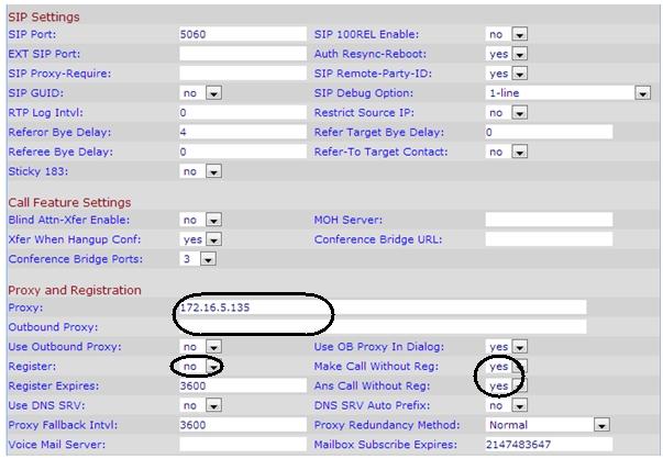
6 Configuring of SIP-devices is performed through the Web-interface. Information about configuring the SIP-device can be found in the official documentation for this device. Configuring of SIP-device is performed the following way: change IP-address of SIP-device if it s needed; set parameters of SIP protocol; add the Intercom Subsystem Server of security intercom terminals to the SIP-device contact list (for GAI Tronics HelpPoint); set the call direction (to the Intercom Subsystem Server) while clicking the call button on the SIP-device (for GAI Tronics HelpPoint); configure IP video server (for LinkSys SPA-2102). Configuration of the GAI Tronics HelpPoint SIP-device The GAI-Tronics HelpPoint SIP-device is configured through the Web-interface the following way: Change IP-address of SIP-device on the IP Settings tab if it s needed; Specify parameters of SIP protocol on the SIP Settings tab. 6
 User ID for connecting to the SIP-device 2 PROXY Empty field Proxy-server is not in use Call from the SIP-device readdresses directly to the Intercom Subsystem Server 3 REGISTRAR Empty field")
7 Parameter Parameter value Information 1 LOCALID Sequence of symbols (letters, digits etc.) User ID for connecting to the SIP-device 2 PROXY Empty field Proxy-server is not in use Call from the SIP-device readdresses directly to the Intercom Subsystem Server 3 REGISTRAR Empty field Readdress Server is not in use 4 USERNAME Sequence of symbols (letters, digits etc.) User name of SIP-device. Should coincide with LOCALID parameter value 7
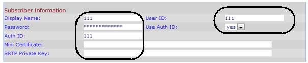
 Password to connect to the SIP-device 6 ENDPOINT ENABLED SIP-device activated Add the Intercom Subsystem Server of security intercom terminals to the contact list of SIP-device on page 1 «Memories")
8 5 PASSWORD Sequence of symbols (letters, digits etc.) Password to connect to the SIP-device 6 ENDPOINT ENABLED SIP-device activated Add the Intercom Subsystem Server of security intercom terminals to the contact list of SIP-device on page 1 «Memories & Comfort Strings» of the «Dialing & Memories» tab. 4. Parameter Parameter value Information 1 MEMORY sip:<name>@<ip address> SIP URL consists of two parts: <name> -user name. It is ignored while calling <IP address> - IP-address of Intercom Subsystem Server 2 COMFORT Sequence of numbers Use to configure calls addressing from SIP-device (see step 4) Set the call direction while clicking the call button on page 2 «Memory Lists» of the «Dialing & Memories» tab. 8
9 Parameter Parameter value Information 1 Number Sequence of numbers Number of required call button 2 WAKEANDIAL ON Includes the call addressing to the Intercom Subsystem Server while clicking the required button 3 LIST Sequence of numbers Should coincide with COMFORT parameter value, corresponding to the SIP URL of required Intercom Subsystem Server (see step 3). Configuring of the «GAI-Tronics HelpPoint» SIP-device through the Web-interface is completed. Configuration of the LinkSys SPA-2102 SIP-device The LinkSys SPA-2102 SIP-device is configured through the Web-interface the following way: The configuration is performed with connected SIP-device through the Ethernet port. Change IP-address of SIP-device on the Wan Setup tab if it s needed and allow its administrating from outside ( Enable WAN web server yes, disabled on default). 9

10 It is recommended to switch the internal Ethernet port of SIP-device which is in use to connect video server to the Bridge mode on the L AN Setup tab. The device administrating through this port is available only through the Internet port. To define the current IP address on the internal device port, connect the telephone to the Line1 port, listen to the voice answer and enter ****, then 210 and # in the tonal mode. To define the external IP address enter **** 110 #. Set parameters of the SIP protocol on the Line1 tab. 10
11 11
12 Configuring of the LinkSys SPA-2102 SIP-device through the Web-interface is completed. Configuration of the AxisQ7401 video server The AxisQ7401 video server is performed the following way: Go to the Setup > System Options > Ports & Devices > I/O Ports section. Set required port name, on which the call duplication DBL signal from security intercom terminal is connected. On default, port 0 for the Axis Q740 Set the type for it: input (Input) Normal State is: open circuit (open circuit state is normal short circuit of the port is performed by call initiation). 12
13 4. To check, assure that the port state is changed into the Active while the call button clicking on the Setup >System Options > Port & Devices > I/O Ports tab. This contact can be in use to show automatically the camera in full screen while the call receiving. Configuration of the Intercom Subsystem of security intercom terminals 13
 and 23 (telnet) are to be opened for correct working of Intercom Subsystem on the computer where the Intercom Subsystem object is created.")
14 Procedure of configuring the Intercom Subsystem Configuring the Intercom Subsystem is performed the following way: 4. Ports 80 (http) and 23 (telnet) are to be opened for correct working of Intercom Subsystem on the computer where the Intercom Subsystem object is created. Configure the Computer system object corresponding to the Intercom Subsystem in the Intellect software; Configure the SIP-device in the Intellect software; Configure the video subsystem of security intercom terminals in the Intellect software; Configure the monitoring of security intercom terminals in the Intellect software. Select disks for storing the archive of audio and video subsystem of security intercom terminals To select disks for storage the archive of video and audio subsystem of security intercom terminals, do the following: Go to the Hardware tab of System settings dialog box In object tree of the Hardware tab select the Computer object corresponding to the Intercom Subsystem Server (1). As a result the settings panel of selected object will display. Names of local disks available for storage the archive of video and audio subsystem of security intercom terminals are presented in the Disk column of Disks for storing the archive table. The corresponding disks spaces in gigabytes (Gb) are presented in the GB column (3). Set the checkbox in the Video column close to those disks which are to be selected for storing the video records archive and synchronous video and audio records (3). Set the checkbox in the Audio column close to those disks which are to be selected for storing the audio records archive (3). To save changes click Apply button (4). Disks selection for storing the archive of video and audio subsystem of security intercom terminal is completed. Configuration of SIP-devices in the Intellect software 14
15 Procedure of configuring of SIP-devices in the Intellect software To configure SIP-devices in the Intellect software, do the following: 4. Configure the Video Capture Device system object corresponding to the SIP-device. Configure audio subsystem of SIP-device in the Intellect software. Configure the Sensor object corresponding to the operator call button on the SIP-device. Arm the Sensor object. The Sensor object of SIP-device is program generated and is not connected directly with relay outputs of Axis video server, call button and call duplicate of security intercom terminal card. Configuration of the Video Capture Device object corresponding to the SIP-device To configure the Video Capture Device object corresponding to SIP-device, do the following: On the Hardware tab select the Computer object corresponding to the Intercom Subsystem Server. 15
. In the opened box set the number and name of Video Capture Device object and then click Apply button.")
16 Click the right mouse button on the Computer selected object and choose the Create object - > Video Capture Device item in the context menu). In the opened box set the number and name of Video Capture Device object and then click Apply button. 16
. In the IP-address and Port fields enter the IP-address and port of SIP-device (2).")
.")
17 4. As a result the settings panel of Video Capture Device object will display From the Type drop-down list select the SIP value (1). In the IP-address and Port fields enter the IP-address and port of SIP-device (2). In the Name and Password fields enter the user name and password to connect to the SIP-device (3). To save changes click Apply button (4). Create the Camera object on the basis of the Video Capture Device object even if camera is not connected to it. It is required for working with SIP-device audio subsystem. 17

18 10. Repeat steps 1-9 for all required SIP-devices. Configuring of Video Capture Device object corresponding to the SIP-device is completed. Configuration of the SIP-device audio subsystem in the Intellect software To configure the audio subsystem if SIP-device in the Intellect software, do the following: On the Hardware tab select the Computer object corresponding to the Intercom Subsystem Server. Click the right mouse button on the Computer selected object and choose the Create object - > Audio Card item from the context menu. In the opened box set the number and name of Audio Card object and then click Apply button. 18
. To save changes click Apply button (2).")
19 4. As a result the settings panel of Audio Card object will display From the Plate drop-down list select the IpCam SIP <IP-address> value where <IP-address> - IP-address of SIP-device (1). To save changes click Apply button (2). Create the Microphone object corresponding to the microphone of SIP-device. On the Hardware tab select the Audio Card object created on 1-6 steps. 19


20 8. 9. Click the right mouse button on selected Audio Card object and choose the Create object - > Microphone item from the context menu. In the opened box enter the number and name of Microphone object and then click Apply button. 10. As a result the settings panel of Microphone object will display. 20

21 From the Channel drop-down list select the IpCam SIP <IP-address> LineIn(#0) value, where <IP-address > - IP address of SIP-device. To save changes click Apply button. Create the virtual microphone for mixing audio stream from the microphone and audio stream receiving to speaker of SIP-device to the single audio stream. Repeat steps 7-10 for it. From the Channel drop-down list select the IpCam SIP <IP-address> LineIn(#1) value where <IP-address > - IP address of SIP-device and click Apply button. 15. Repeat steps 1-14 for all required SIP-devices. Configuring of SIP-devices audio subsystem in the Intellect software is completed. Configuration of the Sensor object corresponding to the operator call button on the SIP-device To configure the Sensor object corresponding to the operator call button on the SIP-device, do the following: On the Hardware tab select the Video Capture Device object corresponding to the SIP-device. Click the right mouse button on the selected Video Capture Device object and choose the Create object -> Sensor item from the context menu. 21


22 In the opened box enter the number and name of the Sensor object and then click Apply. 4. As a result the settings panel of Sensor object will display. 22

23 5. 6. Set the Alarm at switch on checkbox (1). To save changes click Apply button (2). Configuring of the Sensor object corresponding to the operator call button on SIP-device is completed. Arm the SIP-device sensors Sensors corresponding to the operator call button on SIP-devices are to be armed for correct working of Intercom Subsystem. Arming of SIP-device sensors is performed with the help of following objects: 4. The Sensor object of SIP-device is program generated and is not connected directly with relay outputs of Axis video server, call button and call duplicate of security intercom terminal card. Map (the Interface tab); Macro (the Programming tab); Program (the Programming tab); Scrypt (the Programming tab). Working with these objects and sensors arming is described in detail in Administrator s Guide, and Operator s Guide. Configuration of the security intercom terminals video subsystem in the Intellect software Configuring the video subsystem of security intercom terminals in the Intellect software is performed by standard configuring procedure of acceptance and processing video signals from IP-devices (see Administrator's Guide). IP-devices of all security intercom terminals which are to be monitored are registered on the computer where the Intercom Subsystem object is created (Intercom 23

24 Subsystem Server). Specify the corresponding settings on settings panel of the Camera object for synchronous record of mixed audio stream and video signal from security intercom terminals. From the R ecording audio drop-down list select the name of Microphone object corresponding to virtual microphone of security intercom terminals. Configuration of the security intercom terminals monitoring in the Intellect software Configuration of security intercom terminals monitoring in the Intellect software is performed the following way: Configure the Intercom Subsystem object. Create and configure the Intercom object on the basis of Intercom Subsystem object. Configuration of the Intercom Subsytem system object To configure the Intercom Subsytem system object, do the following: On the Hardware tab select the Computer object corresponding to the Intercom Subsytem Server. 24


25 Click the right mouse button on the selected Computer object and choose the Create object - > Intercom Subsytem item from the context menu. In the opened box enter the number and name of Intercom Subsytem object and then click Apply button. 4. As a result the settings panel of the Intercom Subsytem object will display. 25
26 5. 6. In the Timeout (sec): field enter the time in seconds after which the call from SIP-device will be deleted from the processing queue (1). To save changes click Apply button (2). Configuration of the Intercom Subsytem object is completed. Configuration of the Intercom object The Intercom performs the following functions: provides the interaction between the security intercom terminals and the Intellect software; provides the coordinated functioning of devices installed on the security intercom terminals: 1 microphone of SIP-device; 2 speakers of SIP-device; 3 operator call button on SIP-device; 4 IP-video camera. Intercom is created and configured separately for each security intercom terminal which is to be connected to the Intercom Subsystem. To configure the Intercom, do the following: Select the Intercom Subsystem on the Hardware tab. 26


27 Click the right mouse button on the selected Intercom and choose the Create object - > Intercom item from the context menu. In the opened box enter the number and name of Intercom and then click Apply button. 4. As a result the settings panel of Intercom will display. 27
.")
28 From the Sensor drop-down list select the Sensor object corresponding to the operator call button on SIP-device of security intercom terminals (1). From the Camera drop-down list select the Camera object corresponding to the video camera of security intercom terminal (2). From the Microphone drop-down list select the Microphone object corresponding to the microphone on SIP-device of security intercom terminals. From the Commutable output line adapter drop-down list select the Microphone object corresponding to the virtual microphone mixer of audio streams of SIP-device (see the Configuration of the SIP-device audio subsystem in the Intellect software section) - 4). To save changes click Apply button (5). Repeat steps 1-9 for all required security intercom terminals. Configuration of the Intercom is completed. The Client configuration (operator workplace) Procedure of the Client configuration is follows: In the Intellect software register Clients including to the sub-network as the computer where the Intercom Subsystem object is created. On the Architecture tab configure the interaction between the computer where the Intercom Subsystem object is created and Clients. Configure the Client audio subsystem. Configure the Client user interface. Configure the operator rights for working with Intercom Subsystem (optionally). Registration and configuration of interaction between Clients and Intercom Subsystem Registration and configuration of the interacting between Clients and Intercom Subsystem is performed by standard procedure of configuring the distributed system (see the Administra tor's Guide document). Example of configuring the distributed system of security intercom terminals monitoring with one Server and two Clients is follows. 28

29 Configuration of the Client audio subsystem To configure the Client audio subsystem, do the following: Detail information about audio subsystem configuration can be found in the Administrator's Guide document. On the Intercom Subsystem Server of security intercom terminal go to the Hardware tab of System settings dialog box. 29

30 4. 5. Select the Computer object corresponding to the configured Client from the object tree on the Hardware tab. On the basis of this object create and configure the Audio card object corresponding to the audio card installed on the Client. On the basis of Audio Card object create and configure the Microphone object corresponding to the Client microphone which will be in use while communication sessions with SIP-device. Repeat steps 1-4 for all required Clients. Configuration of the Client audio subsystem is completed. Configuration of the Client user interface Procedure of configuring the Client user interface is follows: Create the Display interface object on the computer corresponding to the Intercom Subsystem Server. 4. The Display object is created on the Server for each Client separately. In the basis of Display object create and configure the Monitor interface object on which the video image from video camera of security intercom terminal will display while calling. On the basis of Display object create and configure the Audio player interface object for audio signals record and playback. On the basis of Display object create and configure the Intercom Control Monitor interface object. It s needed to create Monitor, Audio player and Intercom Control Monitor interface objects on the basis of Display object available for the selected Client. Avoid intercrossing of windows of Monitor, Audio player and Intercom Control Monitor interface objects for efficient operator working. 5. Repeat steps 2-4 for all required Clients. 30

31 Configuration of the typical interface objects in the intellect software The following typical interface objects are in use for monitoring of security intercom terminal: Typical objects of the Intellect software are widely used objects in digital systems of video surveillance and audio control built on the basis of Intellect software. Display displays components of user interface which are in use for security intercom terminals; Monitor displays video from the video camera of security intercom terminals while calling; Audio player records and playbacks audio signals from the operator and/or SIP-device. Configuration of typical interface objects in the Intellect software is performed as follows: Detail information about typical interface objects configuration can be found in the Administrator's Guide document. Attention! Display 4321, Monitor 4321 and Audio player 4321 names are reserved for objects which are in use to view the archive by calls from the Reports wizard for security intercom terminal window (see the Report log). It is not recommended to use these names for typical interface objects configuration to avoid the incorrect working of the system. Create the Display object on the Intercom Subsystem Server. On settings panel of the Display object set the checkbox close to a Client for which this object will be available. On the basis of Display object create the Monitor object on which video from the video camera of security intercom terminals while calling will display. Add video cameras which are to be monitored to the List table. 31

32 Create the Audio player object on the basis of the Display object. From the Name column select the Microphone object corresponding to the Client microphone for which the Display object is available. Then select Microphone objects corresponding to physical and virtual microphones of all SIP-devices connected to the Intercom Subsystem Server. Voice notification of the Audio player is to be enabled because it is in use for notification of operator. Configuration of typical interface objects of the Intellect software is completed. Configuration of the Intercom Control Monitor interface object Procedure of configuring the Intercom Control Monitor interface object is follows: Create the Intercom Control Monitor object on the basis of Display object. Set parameters of Intercom Control Monitor interface object. Select Intercom Subsystems with which the Client will interact. Configure displaying the list of calls in the Intercom Control Monitor interface object. Build the Client configuration. Configure the video transfer to the Intercom Subsystem through the video gate. Create the Intercom Control Monitor object To create the Intercom Control Monitor object, do the following: Select the Display object on the Interface tab of the System settings dialog box. 32


33 Click the right mouse button on the selected Display object and choose the Create objects - > Intercom Control Monitor item from context menu. In the opened box enter the number and name of the Intercom Control Monitor object and then click Apply. As a result the settings panel of created object will display. Creation of the Intercom Control Monitor object is completed. Set parameters of Intercom Control Monitor interface object It is possible to configure the following parameters of the Intercom Control Monitor interface object: coordinates of the window; 33
34 size of the window. To set parameters of the Intercom Control Monitor interface object, do the following: Go to the settings panel of the Intercom Control Monitor interface object Set the coordinates of the left upper corner of the Intercom Control Monitor interface window: field «X» (horizontal indent from the left border of the computer s screen) and «Y» (vertical indent from the upper border of the computer s screen) (1-2). Coordinates are set in percentage in according to screen s size horizontally and vertically respectively. Set the sizes of the Intercom Control Monitor interface component: fields «W» (component s width) and «H» (component s height) (3-4). Coordinates are set in percentage in according to screen s size horizontally and vertically respectively. Set the Allow moving checkbox to allow moving of the Intercom Control Monitor interface window. To save changes click Apply button (6). Setting parameters of the Intercom Control Monitor interface object is completed. Select Intercom Subsystems To select Intercom Subsystems for working with Client, do the following: Go to the settings panel of the Intercom Control Monitor interface object. 34

35 4. From the drop-down list in the Number column of Servers group select the number of required Intercom Subsystem object. As a result the name of selected object will automatically display in the Server column of Servers group. Repeat steps 2-3 for all required Intercom Subsystem objects. To clear the table, click the Clear button. To select all registered Intercom Subsystems in the system, click the All button. 5. To save changes click the Apply button. Selecting of Intercom Subsystems for working with Client is completed. Configure displaying the list of calls To configure displaying the list of calls from security intercom terminals in the Intercom Control Monitor interface object, do the following: Go to the settings panel of the Intercom Control Monitor interface object. 35
. 4. 5. 6. 7. 8. 9. 10. 1 1 1 14.")
36 Choose the selection color of accepted call by operator in the Intercom Control Monitor interface object. Double-click the left mouse button on the Processed field of the Sig nalization display group (1) The Processed term means that connection between operator and person which use the SIP-device of security intercom terminal established. In the opened Windows OS standard dialog box select the required color and click OK. Choose the selection color of suspended call by operator in the Intercom Control Monitor interface object. Double-click the left mouse button on the Suspended field of the Sig nalization display group (2). In the opened Windows OS standard dialog box select the required color and click OK. Choose the selection color of a call received by another operator in the Intercom Control Monitor interface object. Double-click the left mouse button on the Another operator: Processed field of the Signalization display group (3). In the opened Windows OS standard dialog box select the required color and click OK. Choose the selection color of a call suspended by another operator in the Intercom Control Monitor interface object. Double-click the left mouse button on the Another operator:suspended field of the Signalization display group (4). In the opened Windows OS standard dialog box select the required color and click OK. Choose the selection color of a call processed in half-duplex mode (audio signal transmitting only in Termina l -> Operator direction). Double-click the left mouse button on the Channel Operator -> communication terminal disabled field of the Signalization display group (5). In the opened Windows OS standard dialog box select the required color and click OK. In the Displayed signalizations field enter the number of calls (waiting for, received, suspended) displayed in the list of the Intercom Control Monitor interface object. Set the Request to confirm Delete operation checkbox if it s needed to confirm the deleting if call from the list. To save changes click Apply button. Configuration of displaying the list of calls from security intercom terminals in the Intercom Control Monitor interface object is completed. Client configuration To configure the Client, do the following: 36
37 Go to the settings panel of the Intercom Control Monitor interface object From the Monitor drop-down list select the Monitor object available for this Client (1). From the Audio player drop-down list select the Audio player object available for this Client (). From the Microphone drop-down list select the Microphone object corresponding to the Client microphone which will be in use during the communication sessions with SIP-device (3). To save changes click Apply button (4). The Client configuration is completed. Configure the video transfer to the Intercom Subsystem through the gate To configure the video transfer to the Intercom Subsystem through the video gate, do the following: Go to the settings panel of the Intercom Control Monitor interface object. 37
38 4. From the Number drop-down list of Cameras table select the number of video camera from which the video image is to transferred to the Intercom Subsystem through the gate (1). As a result the name of selected video camera will automatically display in the Camera column of Cameras table (2). From the Gate drop-down list select the name of required Video gate object (3) Detail information about the Video gate object can be found in the Administrator's Guide document. Repeat steps 2-4 for all required video cameras of security intercom terminals. To save changes click the Apply button (4). Configuring the video transfer to the Intercom Subsystem through the gate is completed. Setting the operator rights for working with Intercom Subsystem It is recommended to restrict the operator rights for the following actions: Select microphones for listening to sound; Control the record of video and audio archive; Change the system settings (in case of Server configuration of Intellect software is in use on the Client). Detail information about administrating the user rights can be found in the Administrator's Guide document. Working with the Intercom Subsystem The following interface objects are used to work with the Intercom Subsystem: Monitor; 38

39 Audio player; Intercom Control Monitor Information about working with these interface objects is presented in the Operator's Guide. Calls acceptance Acceptance of calls received on the Intercom Subsystem is performed in the Intercom Control Monitor interface object. Calls in the Intercom Control Monitor interface object are displayed as a list. Completed calls are not displayed. The Intercom Control Monitor is activated while the new call receipt. One of the following statuses can be assigned to the received call: Call status Status description Waiting Accepted Accepted by another operator Call is received to the Intercom Subsystem but is not accepted by operator. Assigns automatically while the call receipt to the Intercom Subsystem. Call on which the operator is communicating the current moment Call on which another operator is communicating the current moment 39
40 Suspended Suspended by another operator Completed Call which was accepted by operator but lately was suspended for a time Call which was accepted by another operator but lately was suspended for a time Call on which the operator broke the connection or finished the communicating Operator can accept the following calls: 4. waiting; suspended; suspended by another operator. Operator can complete the following calls: waiting; suspended; suspended by another operator; accepted. It is impossible to change the status of call accepted by another operator. The operator hears the repeated audio record stored in the «<Intellect installation directory>\wav\client.wav file if only waiting, suspended and/or suspended by another operator calls are present. If there is the accepted call this audio record is not playback. Parameters of «client.wav» and «monitoring.wav» files («<Intellect installation directory>\wav» folder) are coinciding: one channel (15kbit/s) PCM sound with the frequency and discretization depth equals to 8kHz and 16 bits correspondingly is stored in files. The time interval in seconds between two sequent repeats of «client.wav» audio record is specified as a value of «notification_repeat_delay» string parameter in the «HKLM\SOFTWARE\ITV\Intellect\MonitoringCenter» registry key of OS Windows. The call displaying for different statuses. The color of the frame corresponds to his status and depends on settings of Intercom Control Monitor object (see the Configure displaying the list of calls section). 40
41 Functions of call displaying elements are presented in the table. Executed function Information 1 The field displays the video image from the video camera of security intercom terminal The video image frequency is 1 fps 2 The field displays the time of call receiving to the Intercom Subsystem - 3 The field displays the time from the moment of call receipt - 4 The field displays the name of Intercom object corresponding to the security intercom terminal - 5 To accept the call Displays for waiting and suspended calls 6 To complete the call - 7 The field displays the name of Intercom Control Monitor object in which the call was received Displays for accepted calls 8 The field displays the name of user who accepted the call Displays for accepted calls in case of users have rights and passwords for authorization in the Intellect software 9 To assign the Suspended status to accepted call Displays for accepted calls Viewing the video image from video camera of security intercom terminal For the accepted call the video image from video camera of security intercom terminal is automatically displayed on the Video surveillance monitor. It is possible to view the video image from video camera manually without change the call status to the Accepted. This possibility is enabled for the following calls: How to assign user rights and passwords for authorization in the Intellect software is described in the Intellect Software System: Administrator's Guide. While clicking the Close button the following dialog box can be displayed (this function depends on the system settings see the Configure displaying the list of calls section). To complete the call click Yes, to cancel the operation click No button. waiting; suspended; suspended by another operator; 41
42 4. accepted by another operator. To view the video image from video camera of security intercom terminal, do the following: Double-click the left mouse button on the field with video image of corresponding call in the Intercom Control Monitor interface window. As a result the video image from the video camera of security intercom terminal will display in the Monitor interface window. Viewing the video image from video camera of security intercom terminal is completed. Modes of call processing There are two modes of call processing: Duplex mode. Simultaneous translation of audio signal in Operator - Security intercom terminal and Security intercom terminal - Operator directions. Half-duplex mode. Translation of audio signal only in Security intercom terminal - Operator direction is enabled. To switch over the modes click the Space key. Color of frame for selection the call processing in a half-duplex mode is specified on the settings panel of the Intercom Control Monitor object (see the Configure displaying the list of calls section). Call of the SIP-device using the Video surveillance monitor It is possible to send a call to the SIP-device of security intercom terminal using the Video surveillance monitor. To call the SIP-device, do the following: Open the functional menu of the Video surveillance monitor corresponding to the video camera of security intercom terminal. 42

43 4. Select the Call the SIP-device item in the opened functional menu. As a result the call will be sent to the security intercom terminal. Communication between the operator and security intercom terminal is established after the clicking of call button on the security intercom terminal. Receiving and processing of this call is performed in the Intercom Control Monitor window according to Calls acceptance andcall of the SIP-device using the Video surveillance monitor sections. The SIP-device call is completed. Reports log Reports log displays information about working of Intercom Subsystem for the specified time period. It is possible to form the following reports: By calls. Contains detail information about each call for the specified period. By security intercom terminal. Contains detail statistics by calls from each security intercom terminal for the specified period. Working with the reports log is performed the following way: This function is available on the Intercom Subsystem Server only. 43
44 Go to the settings panel of the Intercom Subsystem object for which the report is to be created. To start the reports wizard click the Start Reports wizard button. As a result the Reports wizard for security intercom terminal dialog box will display. 44
. To create the report click the Count button (3).")
45 From the General report: drop-down list select the required report type (1). Select borders of time period for which the report is to be created in calendars available in from and to drop-down lists of Period group (2). To create the report click the Count button (3). As a result the general report will be displayed as a table. To view the archive data by calls double-click the corresponding table line. As a result the Display 4321 interface object with located Monitor 4321 and Audio player 4321 objects will be activated. Playback of archive video record starts automatically. Display 4321, Monitor 4321 and Audio player 4321 objects are automatically created and configured at the first view of archive. 45

46 To export and print the report click the Report button. To close the Reports wizard for security intercom terminal dialog box click the Exit button. Working with the reports log is completed. Intercom Subsystem Reference and Information Guide. Postscript More detailed information on the Intellect software package is presented in the documents titled: Administrator s Guide; Operator s Guide; Installing and configuring security system components guide; Programming Guide (JScript). If while operating the given software product you have faced difficulties and problems, you are welcome to contact us. However before addressing us, we kindly ask you to answer the following questions: What is the problem? When did the problem occurr and what had happened before it occurred? 46
47 Which conditions gave rise to the problem? Remember, that the more detailed and precise information you give us, the faster our experts will resolve your problem. We are striving to improve the quality of our products, and hence welcome any proposals and suggestions how to improve our software and documentation. Please forward your suggestions to the following addresses: Appendix. Hot keys at keyboard control Description of hot keys at control the Intercom Control Monitor interface object using the keyboard is presented in the table. «Hot» keys NumPad 8 Activates the Executed function Main method of function implementation Type of hot key Intercom Control Monitor interface window Via a mouse click Global for Intellect software (function is implemented at some active window) Space For transfer from half-duplex mode of calls processing to duplex mode and v.v. - Local (function is implemented if the Intercom Control Monitor window is active) Enter For assigning the Receive or Suspend status to the selected call depending on its current status Receive and Suspend buttons in the Intercom Control Monitor interface window Local (function is implemented if the Intercom Control Monitor window is active) Esc For finishing the selected call Close button in the Intercom Control Monitor interface window. Local (function is implemented if the Intercom Control Monitor window is active) Detail information about duplex and half-duplex modes can be found in the Modes of call processing section. 47
Face Intellect Software Package
 AxxonSoft Face Intellect Software Package Administrator s Guide Version 1.0.5 Moscow 2011 1 Contents CONTENTS... 2 1 INTRODUCTION... 4 1.1 The purpose and structure of the Guide... 4 1.2 Purpose of Face
POS-Intellect Software Package
 AxxonSoft POS-Intellect Software Package Administrator s Guide Version 2.3 Moscow 2012 1 Contents CONTENTS... 2 1 INTRODUCTION... 5 1.1 The purpose and structure of the Guide... 5 1.2 The purpose of the
ivms320 Platform User Manual
 ivms320 Platform User Manual Version: 9.1.8.5 Table of Contents Chapter 1 Overview... 4 1.1. Description... 4 1.2. Installation... 4 1.3. Uninstallation... 10 1.4. Log in... 13 1.4.1. First Login... 13
IMS Client Operation Guide Version V1.1 Date
 Version V1.1 Date 2015-10-20 About This Document About This Document About This User Manual Please note the following points before using this user manual: This user manual is intended for persons who
PONEMAH V5.30 WITH NOLDUS MEDIA RECORDER 4.0 QUICK START GUIDE
 TECHNICAL NOTE PONEMAH V5.30 WITH NOLDUS MEDIA RECORDER 4.0 QUICK START GUIDE DSI has partnered with Noldus Information Technology, the leading solution provider for human and animal behavioral research
Android Mobile Client. User Guide. Version 2.9.1
 Android Mobile Client. User Guide Version 2.9.1 1. General information about the Android mobile client..................... 3 2. Connecting to the server and working with servers in the Android client........
Axxon Next software package QUICK START GUIDE
 Axxon Next software package QUICK START GUIDE Version 1.2 AxxonSoft Moscow 2012 1 Contents CONTENTS... 1 1 INTRODUCTION... 3 1.1 Document purpose... 3 1.2 Purpose of the Axxon Next software package...
Contents. 1 Introduction... 4
 DMS64 User Manual Contents 1 Introduction... 4 1.1 Summary... 4 1.2 System Requirements... 4 1.3 Installing Guide... 5 1.4 Reinstalling Guide... 8 1.5 Device Register... 10 1.6 DMS64 Display Mode... 16
Quick Start Guide (V1.03) UD.6L0201B1064A01
 UD.6L0201B1064A01") ivms-4200 PCNVR Quick Start Guide (V1.03) UD.6L0201B1064A01 Thank you for purchasing our product. If there is any question or request, please do not hesitate to contact the dealer. This manual applies
ivms-4200 PCNVR Quick Start Guide (V1.03) UD.6L0201B1064A01 Thank you for purchasing our product. If there is any question or request, please do not hesitate to contact the dealer. This manual applies
UC Desktop Client Feature Guide
 1.1 Installation The Quick Start Guide contains the essential information for getting started with the Oxford Networks BroadTouch Business Communicator. Once you receive an email indicating you have been
Android Mobile Client. User Guide. Версия 2.1.0
 Android Mobile Client. User Guide Версия 2.1.0 1. General information about the Android mobile client..................... 3 2. Connecting to the server and working with servers in the Android client........
CMS PRO Software Manual - Beta. Copyright Digimerge 2010
 CMS PRO Software Manual - Beta Copyright Digimerge 2010 [CMS] Manual (Revision Record) Revision Record Date Description Author Version 2010. 02. 05 Development Version 2/66 [CMS] Manual (Contents) Contents
HIP2P Network Video Camera Client Terminal User Manual
 HIP2P Network Video Camera Client Terminal User Manual Document version:5.1 Page 1 of 34 } Preface Thank you for using our company's products. The network video camera client terminal is used to implement
FREUND SIP SW - V SIP-server setup
 FREUND SIP SW - V1.7.13 SIP-server setup Content 1. Product Setup 4 2. Log in and Home 5 3. Menu 9 3.1 Tools 9 3.1.1 Dashboard 9 3.1.2 Extensions 10 3.1.3 Trunks 14 3.1.4 Groups 18 3.1.5 Ring groups 20
W Box VMS BOX T E C H N O L O G I E S.
 W Box VMS BOX T E C H N O L O G I E S www.wboxtech.eu Contents Contents... 1 Overview... 3 1.1 Description... 3 1.2 Running Environment... 3 1.3 Function Modules... 3 Live view... 6 2.1 User Registration
EASI MP-X Series. User Manual EASI MPR. Workstation. MPR Workstation user manual, , rev003
 EASI MP-X Series User Manual EASI MPR Workstation MPR Workstation user manual, 59300234, rev003 Contents MPR Workstation Introduction...1 General...1 Software version...1 Structure of the Network...1 Workstation
CyberData SIP Intercom Integration with 8x8
 CyberData SIP Intercom Integration with 8x8 This document covers the integration of CyberData s SIP Intercom with 8x8. This document was written for 8x8 and the following CyberData Products: 011214 SIP
Configuration and Operation Manual for the SALTO
 AxxonSoft Configuration and Operation Manual for the SALTO Integration Module Version 1.2 Moscow, 2011 Contents CONTENTS... 2 1 LIST OF TERMS... 3 2 INTRODUCTION... 4 2.1 Purpose of document... 4 2.2 Structure
Quick Operation Guide of ivms-4200
 Quick Operation Guide of ivms-4200 V1.02 2012-02-22 Description ivms-4200 is a video management software using a distributed structure to manage all the connectable devices. It can manage the NVR, DVR,
Lorex Client 7.0 & Lorex Message Master
 Lorex Client 7.0 & Lorex Message Master Software Manual English Version 1.0 MODELS: L19WD Series www.lorexcctv.com Includes L19WD800 & L19WD1600 Copyright 2008 Lorex Technology Inc. Table of Contents Table
CMS User's Manual. Version 1.9
 CMS User's Manual Version 1.9 Introduction 0 Introduction [ Principal function ] This CMS Interlocked with megapixel camera. This CMS supports easy connection and registration of the site(camera) This
Mirasys NVR. User s Guide
 Mirasys NVR User s Guide CONTENTS Contents... 2 Before you start... 3 Introduction... 6 Logging in... 9 User interface... 13 Navigator... 16 Cameras... 25 Video outputs... 41 Digital outputs... 46 Digital
VMS-A1 Client Software. User Manual
 VMS-A1 Client Software User Manual Contents Contents... 2 Chapter1. Overview... 4 1.1 Description... 4 1.2 Features & Functions... 4 Chapter2. Update Info... 6 Chapter3. Starting VMS-A1... 7 3.1 Installing
SecuGuard. Basic 5.0. User s manual. Dec Version: 5.0.x
 SecuGuard Basic 5.0 User s manual Dec. 2009 Version: 5.0.x SecuGuard Basic System Requirement...5 Installation...6 Before Installing the Software... 6 Starting the Installation... 6 Quick Start...9 Install
Copy9 USER GUIDE For Android OS 1.5, 1.6
 Copy9 USER GUIDE For Android OS 1.5, 1.6 1/16 Table of Contents 1. BEFORE USE THIS DOCUMENT...3 2. Download....3 2.1. Download with a PC....3 2.2. Download directly to your smartphone...6 3. Installation....6
NVMS User Manual
 NVMS-1000 User Manual Contents 1 Software Introduction...1 1.1 Summary... 1 1.2 Operation Environment... 1 1.3 Install and Uninstall... 2 1.3.1 Install the Software... 2 1.3.2 Uninstall the Software...
VoIP Overview. Device Setup The device is configured via the VoIP tab of the devices Device Properties dialog in Integration Designer.
 VoIP Overview DESCRIPTION: RTI devices with VoIP (Voice over IP) support currently support peer-to-peer communication with other RTI devices and 3rd party devices that support the SIP protocol. Audio is
Ver HDxViewer. Manual
 Ver. 13.09.06 HDxViewer Manual Symbols and Letters used in this Manual Importance mark : Arrangement of items to be considered for completing work Additional information or tip to avoid in order to completing
IP WEB User Manual V2.0
 IP WEB User Manual V2.0 Please read carefully before installing or contacting your supplier. The information contained at the time of printing is correct, but is subject to change without notice. This
Movi for Mac: Learning a step by step setup for remote MAC users, and MOVI.
 Movi for Mac: Learning a step by step setup for remote MAC users, and MOVI. 1. You can download the program and installation instructions from the following location: http://ilocker.bsu.edu/users/vnic/world_shared/movi4-2.zip
Manual Version: V1.01. ISS Manager Video Management Software User Manual
 Manual Version: V1.01 ISS Manager Video Management Software User Manual Notice The information in this manual is subject to change without notice. Every effort has been made in the preparation of this
DCMS. User Manual. Version V1.0
 DCMS User Manual Version V1.0 About This Document About This Document About This User Manual Please note the following points before using this user manual: This user manual is intended for persons who
Table of Contents Surveillance Center Overview...3 Log...30 Live Camera Panel...31 Live Camera Panel Explained I...32
 Surveillance Center Overview...3 Introduction...3 System Requirements... 4 Features... 5 Checking the Hardware Requirements... 6 Installing and Accessing the Module... 8 Connecting a Camera to the Network...
Test Delivery System. Test Administrator User Guide LOUISIANA ELPS and ELPT. Published July 6, Updated October 12, 2018
 LOUISIANA ELPS and ELPT Test Delivery System Test Administrator User Guide 2018-2019 Published July 6, 2018 Updated October 12, 2018 Prepared by the American Institutes for Research Descriptions of the
AVerMedia. CM3000 Central Management System. User Manual
 AVerMedia CM3000 Central Management System User Manual DISCLAIMER No warranty or representation, either expressed or implied, is made with respect to the contents of this documentation, its quality, performance,
MagicInfo VideoWall Author
 MagicInfo VideoWall Author MagicInfo VideoWall Author User Guide MagicInfo VideoWall Author is a program designed to construct a VideoWall layout and create VideoWall content by adding various elements
STORM Video Management Software User s Manual
 STORM Video Management Software User s Manual Version 2.0.1 Table of Contents 1. OVERVIEW AND ENVIRONMENT... 1 1.1 Overview... 1 1.2 STORM Interface... 1 2. LOGIN... 5 2.1 Initialize Device... 5 2.2 Login
Instruction Manual. Software for managing the By-Me system using Microsoft Media Center. Installer Manual
 Instruction Manual Software for managing the By-Me system using Microsoft Media Center Installer Manual Vimar End-User License Contract VIMAR SPA located in Marostica (VI), Viale Vicenza n. 14, sole owner
USER MANUAL. Mac Version
 USER MANUAL Mac Version Contents 1 Software Introduction... 1 1.1 Summary... 1 1.2 Install and Uninstall... 1 1.2.1 Install the Software... 1 2 Login Software... 3 2.1 Login... 3 2.2 Control Panel Instruction...
HikCentral Control Client. User Manual
 HikCentral Control Client User Manual Legal Information User Manual 2018 Hangzhou Hikvision Digital Technology Co., Ltd. About this Manual This Manual is subject to domestic and international copyright
NVMS User Manual. Version 2.1.0
 NVMS-1000 User Manual Version 2.1.0 Contents 1 Software Introduction... 1 1.1 Summary... 1 1.2 Operation Environment... 1 1.3 Install and Uninstall... 2 1.3.1 Install the Software... 2 1.3.2 Uninstall
DiViS Net (Integration)
") DiViS Net (Integration) Installation and User s Guide Ver 12.00.1 Digital Video Security System Digital Video Recorder www.divisdvr.com Chance-i USA Corp. *All contents of this document may change without
DiViS Net (Integration) Installation and User s Guide Ver 12.00.1 Digital Video Security System Digital Video Recorder www.divisdvr.com Chance-i USA Corp. *All contents of this document may change without
Centralized monitoring software Monas-NET
 Communications for security Centralized monitoring software Monas-NET (Version 1.56) User guide Content 1. Application of the programme MONAS-NET 3 2. Security of the programme 3 3. Programme components
Changing Settings for ViewMail for Outlook (Version 8.0 Only)
") Changing Settings for ViewMail for Outlook Note This content applies to ViewMail for Outlook version 8.0 only. For later ViewMail versions, see the Quick Start Guide for Cisco ViewMail for Microsoft Outlook
Changing Settings for ViewMail for Outlook Note This content applies to ViewMail for Outlook version 8.0 only. For later ViewMail versions, see the Quick Start Guide for Cisco ViewMail for Microsoft Outlook
Operation Guide. ismartviewplus V1.0.2 (For windows) July, 2017 Rev1.0
 July, 2017 Rev1.0") Operation Guide ismartviewplus V1.0.2 (For windows) July, 2017 Rev1.0 Statement If the user manual doesn t help you to resolve the problem, please contact us via our website for technical support. Notice
Operation Guide ismartviewplus V1.0.2 (For windows) July, 2017 Rev1.0 Statement If the user manual doesn t help you to resolve the problem, please contact us via our website for technical support. Notice
SecuGuard. Basic 5.0. Version: xxx
 SecuGuard Basic 5.0 Ł` ˆª Ø Version: 5.0.2.xxx SecuGuard Basic ` Ø ˆ ˆ...6 ˆ Ø...7 Ł ˆ Ø»ˆÆ ˆ`... 7 ˆŁ` ˆ Ø»ˆÆ ˆ`... 7 Ø Æ Ł...10 Ø IP Camera(s)... 10 Ł` IP Camera(s)... 10 ˆ Ø Ł ˆ ˆ :... 14 Playback:...
CommPortal Communicator Desktop End User Guide 19 Feb 2014
 End User Guide 19 Feb 2014 Integra Hosted Voice Service PC Communicator Desktop End User Guide 19 Feb 2014 21 Feb 20134 End User Guide Contents 1 Introduction... 1-1 1.1 Using this End User Guide... 1-2
TruVision DVR 30 Quick Start Guide
 TruVision DVR 30 Quick Start Guide Content Contact information 1 Package contents 1 Installation environment 1 Setting up the TVR 30 1 Connecting the devices 2 Turning on the TVR 30 2 Operating the TVR
NVMS User Manual
 NVMS-1000 User Manual Contents 1 Software Introduction...1 1.1 Summary... 1 1.2 Operation Environment... 1 1.3 Install and Uninstall... 2 1.3.1 Install the Software... 2 1.3.2 Uninstall the Software...
Data Maintenance Tool
 DT700 Series Data Maintenance Tool User's Guide A50-017029-001 Ver. 1.2 June 2009 Notice (1) Information in this guide is subject to change without notice. (2) If you find any unclear or incorrect description
Guarding Expert Client Software. User Manual UD02162N
 Guarding Expert Client Software User Manual UD02162N User Manual About this Manual This Manual is applicable to Guarding Expert Client Software. The Manual includes instructions for using and managing
RemoteManager Software
 RMS RemoteManager Software User Manual Contents of this user manual are protected under copyrights and computer program laws. Functions or configurations are subject to be changed or modified without prior
NVMS1000. User Manual
 NVMS1000 User Manual Contents 1 Software Introduction... 1 1.1 Summary... 1 1.2 Operation Environment... 1 1.3 Install and Uninstall... 2 1.3.1 Install the Software... 2 1.3.2 Uninstall the Software...
TRIDENT - CMS Plus. 64CH Central Management System Software
 TRIDENT - CMS Plus 64CH Central Management System Software Please read instructions thoroughly before operation and retain it for future reference. For video demonstration about CMS Lite operation, please
Central Management Software. Cam Viewer 3 Lite. User Manual
 Central Management Software Cam Viewer 3 Lite User Manual Version 1.0.0 Table of Contents 1. System Requirement...4 2. Software Installation...5 3. Configuration Wizard...9 3.1 Channel...10 3.1.1 Adding
IS-381 / IS-382 IP Audio gateway. User Manual
 IS-381 / IS-382 IP Audio gateway User Manual IS-381 IS-382 PORTech Communications Inc. Content 1. Introduction... 1 2. Functions... 1 3. Parts list... 2 4.Main body size... 2 5.Panel description... 3 6.Link
Video recorders DX Series
 Page: 1 AHD DVR cameras, analog, IP CMS Program Manual How to install and use the client program to the DVR Page: 2 Contents of this handbook This manual describes how to install and use the CMS program
truvision DVR 31 Quick Start Guide
 truvision DVR 31 Quick Start Guide Content Contact information 1 Package contents 1 Installation environment 1 Setting up the DVR 31 1 Connecting the devices 2 Turning on the DVR 31 2 Operating the DVR
AT&T Connect Participant Application User Guide Integrated Edition Version 8.9 January 2010
 AT&T Connect Participant Application User Guide Integrated Edition Version 8.9 January 2010 at&t 2009 2010 AT&T Intellectual Property. All rights reserved. AT&T and the AT&T logo are trademarks of AT&T
GV-VMS. New Feature Guide V VMSV FG-B
 GV-VMS New Feature Guide V15.10.1.0 VMSV151010-FG-B 2016 GeoVision, Inc. All rights reserved. Under the copyright laws, this manual may not be copied, in whole or in part, without the written consent of
Senstar Symphony. 7.1 User Guide
 Senstar Symphony 7.1 User Guide Contents Contents Introduction...5 Network configuration... 5 Getting started...6 Symphony Server... 8 Log in to the server configuration interface...8 Devices...8 Cameras...
Troubleshooting and Getting Help
 CHAPTER 16 This section provides troubleshooting information for common Cisco Unified MeetingPlace Express issues. How to Get Help, page 16-1 How to Resolve Log In Problems, page 16-2 How to Resolve Schedule
TS View Client Software. User Manual
 TS View Client Software User Manual 2016-03-03 User Manual About this Manual This Manual is applicable to TS View Client Software. The Manual includes instructions for using and managing the product. Pictures,
Digital Video Surveillance Center Management Software
 Digital Video Surveillance Center Management Software NVClient User Manual Revision: V3.2 Updated: 12-2011 Contents Chapter I General...- 3-1.1 INTRODUCTION... - 3-1.2 MAIN FUNCTIONS... - 3 - Chapter II
Sipelia User Guide 2.0 GA. Click here for the most recent version of this document.
 Sipelia User Guide 2.0 GA Click here for the most recent version of this document. Copyright notice 2015 Genetec Inc. All rights reserved. Genetec Inc. distributes this document with software that includes
INSTRUCTION MANUAL. ATVision IP. Please read this manual thoroughly before use, and keep it handy for future reference.
 INSTRUCTION MANUAL ATVision IP Please read this manual thoroughly before use, and keep it handy for future reference. Table of Contents Chapter 1 Introduction... 1 1.1 Features... 1 1.2 System Requirements...
Digital Voice Softphone User Guide Version 2.0. Digital Voice Softphone User Guide Version 2.0
 Digital Voice Softphone User Guide 1 TABLE OF CONTENTS 1. Set-up... 3 1.1. Using the Digital Voice Softphone... 3 1.2. Digital Voice Softphone Set-up... 3 1.3. System Requirements... 4 1.4. Installing
Quick Start Guide 4/8/16/24-Ch DVR
 Quick Start Guide 4/8/16/24-Ch DVR 1.1 Install Hard Drive 4/8/16/24-CH DVR Quick Start Guide Notice: 1.4/3/16-ch DVR supports one SATA hard drive. 24-ch DVR supports three SATA hard drives. Please use
WV-NS202. Network Operating Instructions. Network Camera. Model No.
 Network Camera Network Operating Instructions Model No. WV-NS202 LOCK OPEN WV-NS202 Before attempting to connect or operate this product, please read these instructions carefully and save this manual for
DiViS Net (Integration)
") DiViS Net (Integration) Installation and User s Guide Ver 11.02.2 Digital Video Security System Digital Video Recorder www.divisdvr.com *All contents of this document may change without prior notice. CHANCE-i
DiViS Net (Integration) Installation and User s Guide Ver 11.02.2 Digital Video Security System Digital Video Recorder www.divisdvr.com *All contents of this document may change without prior notice. CHANCE-i
User s Manual of DVR ULTIMAX. Remote Client Software V wersja 2.40
 User s Manual of DVR ULTIMAX Remote Client Software V 4.0.1 ULTIMAX-304 ULTIMAX-308 ULTIMAX-316 ULTIMAX-504 ULTIMAX-508 ULTIMAX-516 ULTIMAX-704 ULTIMAX-708 ULTIMAX-716 wersja 2.40 Index 1 Software Install,
LOREX CLIENT Remote Agent Software
 LOREX CLIENT Remote Agent Software Instruction Manual English Version 1.0 MODEL: L500 Series www.lorexcctv.com Copyright 2006 LOREX Technology Inc. Table of Contents Table of Contents About the Lorex Client...
Quick Start Guide 4/8/16-CH DVR.
 Quick Start Guide 4/8/16-CH DVR 1. Install Hard Drive &DVD Writer 1.1 Install Hard Drive Notice: 1. Support two SATA hard drives. Please use the hard drive the manufacturers recommend specially for security
APPAREO TRANSFER UTILITY USER GUIDE
 APPAREO TRANSFER UTILITY USER GUIDE Document revision 2.13 Last revised: August 31, 2018 Appareo Transfer Utility User Guide 2009-2018 Appareo Systems, LLC. All Rights Reserved. Appareo Transfer Utility
NVMS7000 Client Software
 NVMS7000 Client Software User Manual User Manual About this Manual This Manual is applicable to NVMS7000 Client Software. The Manual includes instructions for using and managing the product. Pictures,
Accession Communicator for Desktop User Guide Hosted IP Phone System
 Download Accession Communicator: Go to: http://portal.popp.com Number: end user s 10-digit phone number Password: initial password provided by POPP [Login] [Downloads] at the bottom of the screen [View
Index. Guide. Camera Detect Event Guide. AcuraVision
 Index Guide of Camera Detect Events in AcuraVision How to use Motion Detection... 2 How to use Missing & Left Object Detection... 4 How to use Secure Zone Detection... 6 How to use Flow Counting feature...
WebEx Recorder and Player
 WebEx Recorder and Player User s Guide Version 2.8.4902 Copyright WebEx Communications, Inc. and Cisco Systems, Inc. reserve the right to make changes in the information contained in this publication without
Controls. Assisted. Audio ACTION. Captivate your. Connect. This. From. audio STEP Provider drop-down. menu and. field. just Op Assisted.
 USE R GUIDE Adobe Connect Operator Assisted Audio Controls Guide forr Hosts Captivate your audience by integrating Operator Assisted audio conferencing service with the cutting edge Adobe Connect online
Voyant Connect User Guide
 Voyant Connect User Guide WELCOME TO VOYANT CONNECT 3 INSTALLING VOYANT CONNECT 3 MAC INSTALLATION 3 WINDOWS INSTALLATION 4 LOGGING IN 4 WINDOWS FIRST LOGIN 6 MAKING YOUR CLIENT USEFUL 6 ADDING CONTACTS
X30 SIP Paging Gateway User Guide. Software version v1.0.1
 X30 SIP Paging Gateway User Guide Software version v1.0.1 This document is subject to change without notice. The latest electronic version of this user guide is available for downloading here: http://www.zycoo.com/home-download-index-catid-55.html
Railroad Crossing Pilot Study Video System User s Guide. Provided by:
 Railroad Crossing Pilot Study Video System User s Guide Provided by: 1 Table of Contents Installation and Login... 4 Minimum System Requirements... 4 Installation... 4 Logging in with the Ocularis Client...
Blackboard Collaborate Classroom in D2L Brightspace Daylight Experience
 Blackboard Collaborate Classroom in D2L Brightspace Daylight Experience Moderators Guide University Information Technology Services Learning Technology, Training, Audiovisual, and Outreach Copyright 2018
Quick Start Guide GV-VMS
 Quick Start Guide GV-VMS Thank you for purchasing GV-VMS. This guide is designed to assist the new user in getting immediate results from the GV-VMS. For advanced information on how to use the GV-VMS,
Contents Getting Started GV-LPR Application Controls Installation Guidelines
 Table of Contents Getting Started 2 Check Package Contents...........................................2 Requirements....................................................2 Installations......................................................3
Table of Contents: General Settings... 26
 Table of Contents: 1. Software Installation... 1 2. Observer... 2 2.1 Quick Access Panel... 3 2.2 Right Mouse Button Menu... 4 2.3 User Actions... 4 2.4 Connect to Servers... 5 2.5 Choose Screen Division...
Quick Start Guide 4/8/16-Ch DVR
 Quick Start Guide 4/8/16-Ch DVR 1 1. Install Hard Drive &DVD Writer 1.1Install Hard Drive Notice: 1. Support two SATA hard drives. Please use the hard drive the manufacturers recommend specially for security
DMP 128 Plus C V DMP 128 Plus C V AT
 DMP 128 Plus C V DMP 128 Plus C V AT Interactive Intelligence Configuration Guide REVISION: 1.0.1 DATE: MARCH 7 TH 2018 Revision Log Date Version Notes Feb 9 th 2018 1.0 First Release: Applies to Firmware
Unofficial IRONTON ITSP Setup Guide
 September 13 Unofficial IRONTON ITSP Setup Guide Author: Zultys Technical Support This unofficial configuration guide was created to assist knowledgeable vendors with configuring the Zultys MX Phone System
i-phonenet X-Lite (ver 3.0) SoftPhone Setup June 2006 ver 1.0
 SoftPhone Setup June 2006 ver 1.0") i-phonenet X-Lite (ver 3.0) SoftPhone Setup June 2006 ver 1.0 TABLE OF CONTENT 1. REQUIREMENTS AND INSTALLATION...2 2. INSTALLING X-LITE (ONE TIME)...3 3. X-LITE SOFTPHONE SETUP...4 4. QUICK USER GUIDE...9
i-phonenet X-Lite (ver 3.0) SoftPhone Setup June 2006 ver 1.0 TABLE OF CONTENT 1. REQUIREMENTS AND INSTALLATION...2 2. INSTALLING X-LITE (ONE TIME)...3 3. X-LITE SOFTPHONE SETUP...4 4. QUICK USER GUIDE...9
GOM Cam User Guide. Please visit our website (cam.gomlab.com) regularly to check out our. latest update.
 regularly to check out our. latest update.") GOM Cam User Guide Please visit our website (cam.gomlab.com) regularly to check out our latest update. From screen recording to webcam video and gameplay recording GOM Cam allows you to record anything
GOM Cam User Guide Please visit our website (cam.gomlab.com) regularly to check out our latest update. From screen recording to webcam video and gameplay recording GOM Cam allows you to record anything
DiViS Net (Integration)
") DiViS Net (Integration) Installation and User s Guide Ver 12.12.0 Digital Video Security System Digital Video Recorder www.divisdvr.com DiViS DVR.com *All contents of this document may change without prior
DiViS Net (Integration) Installation and User s Guide Ver 12.12.0 Digital Video Security System Digital Video Recorder www.divisdvr.com DiViS DVR.com *All contents of this document may change without prior
Central Management System User s Manual
 Central Management System User s Manual Version 1.4.0 Table of Contents 1. Overview...3 1.1 System Requirement...4 1.2 Supported IP Camera...5 2. Software Installation...6 3. Software Upgrade...10 4. Start
The Intelligent Surveillance Solution. NVR/DVR/Hybrid NDVR Quick User Manual. Ver B
 NVR/DVR/Hybrid NDVR Quick User Manual Ver. 99.350. B0430.001 INSTALLATION The Installation CD contains the software you need to run the complete system. After inserting the CD, you should be able to see
for Windows
 JabberVideo@Facegate for Windows Prerequisites See PC requirements for detail on what is required for your computer to run Cisco Jabber Video for TelePresence (hereafter referred to as Jabber Video). A
BEWARD Record Center
 2011 BEWARD Co., LTD BEWARD Record Center User manual Ver. 1.13 www.beward.net Table of contents Table of contents CHAPTER 1. GENERAL INFORMATION... 3 1.1. BEWARD RECORD CENTER BUNDLED SOFTWARE REVIEW......
i-phonenet X-Lite SoftPhone Setup Mar 2005 ver 1.0
 i-phonenet X-Lite SoftPhone Setup Mar 2005 ver 1.0 TABLE OF CONTENT 1. REQUIREMENTS AND INSTALLATION...2 2. INSTALLING X-LITE (ONE TIME)...3 3. X-LITE SOFTPHONE SETUP...4 4. QUICK USER GUIDE...10 5. TROUBLESHOOTING...11
Two-way Audio IP Cam w/night-vision Software User Guide
 Two-way Audio IP Cam w/night-vision Software User Guide Version 1.0 Contents Introduction...2 Installation...3 Using Ultra View...6 To launch the program...6 Item features...7 To add a camera... 12 To
ntouch for Mac User Guide for Apple OS X Version 3.0 Table of Contents Introducing ntouch for Mac... 2 Quick App Overview... 3
 ntouch for Mac for Apple OS X User Guide Version 3.0 Table of Contents Introducing ntouch for Mac... 2 Quick App Overview... 3 Make and Receive Calls... 10 Use 1-Line Voice Carry Over... 18 Send Deaf SignMail...
For Organizers (Hosts) at OSU
 at OSU") Adobe Connect Pro 8.2 Overview For Organizers (Hosts) at OSU Getting Started 1. Access Adobe Connect Pro Central via this URL: http://oregonstate.adobeconnect.com 2. Login using your email address and
Adobe Connect Pro 8.2 Overview For Organizers (Hosts) at OSU Getting Started 1. Access Adobe Connect Pro Central via this URL: http://oregonstate.adobeconnect.com 2. Login using your email address and