Engine Plant Model Development and Controller Calibration using Powertrain Blockset TM
|
|
|
- Cameron Brown
- 5 years ago
- Views:
Transcription


1 Engine Plant Model Development and Controller Calibration using Powertrain Blockset TM Brad Hieb Scott Furry Application Engineering Consulting Services 2017 The MathWorks, Inc. 1


2 Key Take-Away s Engine model parameterization is a very nontrivial task Engine controller calibration is a very non-trivial task MathWorks has tools to help make these two tasks more manageable 2
3 Problem Statement How do I use the Powertrain Blockset engine and controller models for my application so I can: Design engine controls? Perform fuel economy and emissions studies? Create and validate dynamometer test plans? 3
4 What we ll Cover Today Parameterizing a Powertrain Blockset engine model Workflow Example: parameterizing a mapped engine model Calibrating a Powertrain Blockset engine controller Workflow Example: calibrating an engine controller 4


5 What are we Parameterizing and Calibrating? 5
6 What we ll Cover Today Parameterizing a Powertrain Blockset engine model Workflow Example: parameterizing a mapped engine model Calibrating a Powertrain Blockset engine controller Workflow Example: calibrating an engine controller 6

7 Powertrain Blockset Si Mapped Engine Model Contains 2D LUT s for each model output Easy to parameterize Great for system level design and development 7
8 Parameterizing an Engine Model - Workflow Model-Based Calibration Toolbox provides tools for the process: Design of Experiments Creating the Design of Experiments CAE Engine Model Data Modeling Engine Dynamometer Parameter Generation Results Optimal Engine Calibration Parameters Fast, Accurate Engine Model for HIL and System Simulation 8

9 Parameterizing an Engine Model - Workflow Model-Based Calibration Toolbox provides tools for the process: Design of Experiments Creating the Design of Experiments CAE Engine Model Engine Dynamometer Gather the data Data Modeling Parameter Generation Results Optimal Engine Calibration Parameters Fast, Accurate Engine Model for HIL and System Simulation 9

10 Parameterizing an Engine Model - Get the data as calibrated Measurements Air Flow Fuel Flow Exhaust Temp Emissions BSFC Dynamometer Control (Steady State) Speed Cmd Measurements Torque Cmd. Speed Measured Speed Measured Data Logger Engine System (Change operating points, fixed calibration) Crankshaft Dynamometer Torque Measured 10
11 Parameterizing an Engine Model - Workflow Model-Based Calibration Toolbox provides tools for the process: Design of Experiments Creating the Design of Experiments Gather the data CAE Engine Model Data Modeling Engine Dynamometer Fitting response surface models (RSM, statistical) to the data Parameter Generation Results Optimal Engine Calibration Parameters Fast, Accurate Engine Model for HIL and System Simulation 11
12 Parameterizing an Engine Model - Workflow Model-Based Calibration Toolbox provides tools for the process: Design of Experiments Creating the Design of Experiments Gather the data Fitting response surface models Developing engine performance maps from RSM s CAE Engine Model Engine Dynamometer Data Modeling Parameter Generation Results Optimal Engine Calibration Parameters Fast, Accurate Engine Model for HIL and System Simulation 12
13 Parameterizing an Engine Model - Workflow Model-Based Calibration Toolbox provides tools for the process: Design of Experiments Creating the Design of Experiments Gather the data Fitting response surface models Developing engine performance maps CAE Engine Model Engine Dynamometer Data Modeling Parameter Generation Validate the result Results Optimal Engine Calibration Parameters Fast, Accurate Engine Model for HIL and System Simulation 13

14 Launch MBC Toolbox From Apps tab From command line >> mbcmodel 14

15 Launch MBC Toolbox 15

16 Parameterizing a Mapped Engine Model - Importing existing data Mapped engine model workflow: Design of Experiments Importing existing data CAE Engine Model Engine Dynamometer Data Modeling Parameter Generation Results Optimal Engine Calibration Parameters Fast, Accurate Engine Model for HIL and System Simulation 16

17 Import Data - Inspect the data Look for anomalies or gaps Filter data to remove anomalies Add derived quantities and unit conversions Graphical views speed inspection 17
18 Parameterizing a Mapped Engine Model - Fitting response surface models Mapped engine model workflow: Design of Experiments Importing existing data CAE Engine Model Engine Dynamometer Fitting response surface models (RSM, statistical) to the data Data Modeling Parameter Generation Results Optimal Engine Calibration Parameters Fast, Accurate Engine Model for HIL and System Simulation 18

19 Fitting Models to the Data - Generate response surface models Default models automatically fitted to all responses Inspect quality of fit Try out alternatives 19
20 Parameterizing a Mapped Engine Model - Developing engine performance maps Mapped engine model workflow: Design of Experiments Importing existing data Fitting response surface models CAE Engine Model Engine Dynamometer Developing engine performance maps from RSM s Data Modeling Parameter Generation Results Optimal Engine Calibration Parameters Fast, Accurate Engine Model for HIL and System Simulation 20
21 Calibration Generation Tool Fill tables Export cal tables 21
22 Calibration Generation Tool - Generating look up tables 22

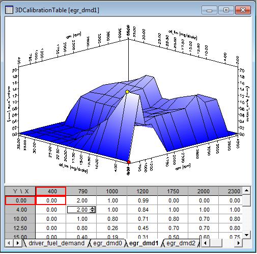
23 Calibration Generation Tool - Fill tables Inspect surfaces Adjust table values in extrapolation areas Export to MATLAB, Excel or Cal tool 23
24 Parameterizing a Mapped Engine Model - Export and validate result Mapped engine model workflow: Importing existing data Fitting response surface models Developing engine performance maps Design of Experiments CAE Engine Model Engine Dynamometer Data Modeling Export and validate the result Parameter Generation Results Optimal Engine Calibration Parameters Fast, Accurate Engine Model for HIL and System Simulation 24


25 Export Tables to MATLAB 25

26 Validate the Result 26
27 Validate the Result Accuracy for 1200 sec of FTP75 sim: % diff in FE was 0.31% Run time for 1200 sec of FTP75 sim: PTBS Mapped engine model 28.4 sec GT Power FRM engine model 1449 sec Mapped engine model sim ~51x faster 27
28 Parameterizing a Mapped Engine Model - Summary Mapped engine model workflow: Design of Experiments Importing existing data CAE Engine Model Engine Dynamometer Fitting response surface models (RSM, statistical) to the data Developing engine performance maps from RSM s Data Modeling Parameter Generation Results Validate the result Optimal Engine Calibration Parameters Fast, Accurate Engine Model for HIL and System Simulation 28
29 What we ll Cover Today Parameterizing a Powertrain Blockset engine model Workflow Example: parameterizing a mapped engine model Calibrating a Powertrain Blockset engine controller Workflow Example: calibrating an engine controller 29
30 What are we Parameterizing and Calibrating? 30
31 What are we Calibrating? Throttle area percent (TAP) Wastegate Fraction Lambda Spark Advance Intake Cam Advance Exhaust Cam Retard 31
32 Calibrating Optimal Base Engine Control Tables - Workflow Model-Based Calibration Toolbox provides tools for the process: Design of Experiments Creating the Design of Experiments CAE Engine Model Engine Dynamometer Gather the data Fitting response surface models (RSM, statistical) to the data Data Modeling Calibration Generation Results Developing optimal base calibration tables Optimal Engine Calibration Parameters Fast, Accurate Engine Model for HIL and System Simulation Export calibration to controller 32
33 Calibrating Optimal Base Engine Control Tables - Creating the DoE Optimal base engine control calibration workflow: Design of Experiments Creating the Design of Experiments CAE Engine Model Data Modeling Engine Dynamometer Calibration Generation Results Optimal Engine Calibration Parameters Fast, Accurate Engine Model for HIL and System Simulation 33
34 Calibrating Optimal Base Engine Control Tables - Creating the DoE I/O of Turbocharged Direct-Injection 1.5L DOHC Engine Model with Dual-Independent Continuously Variable Cam Phasing Table Breakpoints Optimal Tables RPM Load ICP ECP Minimum BSFC Objective Exhaust Temperature Turbocharger Speed Knock limit Residual Fraction AFR Spark Advance Waste-gate area TAP Intake Manifold Pressure Auxiliary Table Constraints Optimal Tables 34


35 Calibrating Optimal Base Engine Control Tables - Creating the DoE 35
36 Calibrating Optimal Base Engine Control Tables - Gather the data Optimal base engine control calibration workflow: Design of Experiments Creating the Design of Experiments CAE Engine Model Engine Dynamometer Gather the data Data Modeling Calibration Generation Results Optimal Engine Calibration Parameters Fast, Accurate Engine Model for HIL and System Simulation 36


37 Calibrating an Optimal Base Cal Table - Get the data from CAE engine models 37
")


38 Calibrating Optimal Base Engine Control Tables - Get the data from calibration sweeps Dynamometer Control (Steady State) Speed Cmd Actuator Cmds. Torque Cmd. Speed Measured Measurements Air Flow Fuel Flow Exhaust Temp Emissions (EO/TP) MAP Measurements MAT A/F Turbo Speed Turbine press ratio Compressor press ratio Speed Measured Turbine temp out Compressor temp out EGR pct. EGR cooler temp out Intercooler temp out Data Logger Actuator Commands Throttle Intake cam Wastegate Exhaust cam Injector EGR valve Spark Turbo Engine (Change operating points and sweep Actuator Cmds) Crankshaft Dynamometer Torque Measured 38
39 Calibrating Optimal Base Engine Control Tables - Fitting response surface models Optimal base engine control calibration workflow: Design of Experiments Creating the Design of Experiments Gather the data Fitting response surface models (RSM, statistical) to the data CAE Engine Model Engine Dynamometer Data Modeling Calibration Generation Results Optimal Engine Calibration Parameters Fast, Accurate Engine Model for HIL and System Simulation 39

40 Calibrating Optimal Base Engine Control Tables - Generate response surface models from data Default models automatically fitted to all responses Inspect quality of fit Try out alternatives 40
41 Calibrating Optimal Base Engine Control Tables - Develop optimal base calibration tables Optimal base engine control calibration workflow: Design of Experiments Creating the Design of Experiments Gather the data Fitting response surface models Developing optimal base calibration tables from RSMs CAE Engine Model Engine Dynamometer Data Modeling Calibration Generation Results Optimal Engine Calibration Parameters Fast, Accurate Engine Model for HIL and System Simulation 41
42 Calibrating Optimal Base Engine Control Tables - Developing calibration tables Import response surface models Run optimizations Analyze tradeoffs and sensitivity Fill tables Export cal tables 42
43 Calibrating Optimal Base Engine Control Tables - Developing calibrations from response surface models Import response surface models Run optimizations Analyze tradeoffs and sensitivity Fill tables Export cal tables 43

44 Calibrating Optimal Base Engine Control Tables - Run optimizations Define objective Define constraints Determine operating point weights 44

45 How to calculate the weights for a sum optimization Use MATLAB to calculate weights for a drive cycle Drive cycle data Weights as % from total time MATLAB program reads measurements from Excel measurement file and calculate weights automatically Histogram 45

46 Calibrating Optimal Base Engine Control Tables - Run optimizations Evaluate optimization results Diagnose optimization convergence issues 46

47 Calibrating Optimal Base Engine Control Tables - Analyze tradeoffs and sensitivity Evaluate local sensitivity Determine if tradeoffs are needed 47

48 Calibration Generation Tool - Fill tables Inspect surfaces Export to MATLAB, Excel or Cal tool 48
49 Optimal Base Calibrations Completed Throttle area percent (TAP) Wastegate Fraction Lambda Spark Advance Intake Cam Advance Exhaust Cam Retard 49
50 Calibrating Optimal Base Engine Control Tables - Export and validate the result Optimal base engine control calibration workflow: Design of Experiments Creating the Design of Experiments Gather the data Fitting response surface models Developing optimal base calibrations CAE Engine Model Engine Dynamometer Data Modeling Calibration Generation Export calibration to controller Results Optimal Engine Calibration Parameters Fast, Accurate Engine Model for HIL and System Simulation 50


51 Export Tables to Calibration Tool 51
52 Calibrating Optimal Base Engine Control Tables - Summary Optimal base engine control calibration workflow: Design of Experiments Creating the Design of Experiments CAE Engine Model Engine Dynamometer Gather the data Fitting response surface models Developing optimal base calibrations Export calibration to controller Optimal Engine Calibration Parameters Data Modeling Calibration Generation Results Fast, Accurate Engine Model for HIL and System Simulation 52
53 Key Take-Away s Engine model parameterization is a very nontrivial task Engine controller calibration is a very non-trivial task MathWorks has tools to help make these two tasks more manageable 53
54 Contact us to Learn More Scott Furry Brad Hieb Design of Experiments CAE Engine Model Engine Dynamometer Data Modeling Calibration Generation Results Optimal Engine Calibration Parameters Fast, Accurate Engine Model for HIL and System Simulation 54

55 Q & A?? 55
Engine Calibration Process for Evaluation across the Torque- Speed Map
 Engine Calibration Process for Evaluation across the Torque- Speed Map Brian Froelich Tara Hemami Manish Meshram Udaysinh Patil November 3, 2014 Outline : Background Objective Calibration process for torque
Creation and Validation of a High-Accuracy, Real-Time-Capable Mean-Value GT-POWER Model
 1 Creation and Validation of a High-Accuracy, Real-Time-Capable Mean-Value GT-POWER Model Tim Prochnau Advanced Analysis and Simulation Department Engine Group International Truck and Engine Corporation
Demonstration of the DoE Process with Software Tools
 Demonstration of the DoE Process with Software Tools Anthony J. Gullitti, Donald Nutter Abstract While the application of DoE methods in powertrain development is well accepted, implementation of DoE methods
Objective Determination of Minimum Engine Mapping Requirements for Optimal SI DIVCP Engine Calibration
 Copyright 2009 SAE International 2009-01-0246 Objective Determination of Minimum Engine Mapping Requirements for Optimal SI DIVCP Engine Calibration Peter J. Maloney The MathWorks, Inc. ABSTRACT In response
ONE DIMENSIONAL (1D) SIMULATION TOOL: GT-POWER
 SIMULATION TOOL: GT-POWER") CHAPTER 4 ONE DIMENSIONAL (1D) SIMULATION TOOL: GT-POWER 4.1 INTRODUCTION Combustion analysis and optimization of any reciprocating internal combustion engines is too complex and intricate activity. It
CHAPTER 4 ONE DIMENSIONAL (1D) SIMULATION TOOL: GT-POWER 4.1 INTRODUCTION Combustion analysis and optimization of any reciprocating internal combustion engines is too complex and intricate activity. It
Controller Calibration using a Global Dynamic Engine Model
 23.09.2011 Controller Calibration using a Global Dynamic Engine Model Marie-Sophie Vogels Johannes Birnstingl Timo Combé CONTENT Introduction Description of Global Dynamic Model Concept Controller Calibration
Transient engine model for calibration using two-stage regression approach
 Loughborough University Institutional Repository Transient engine model for calibration using two-stage regression approach This item was submitted to Loughborough University's Institutional Repository
Model-based Calibration of HD Engines. Benjamin Tilch, Rico Möllmann, Axel Steinmann, Dr. Reza Rezaei GT-SUITE Conference, Frankfurt, October 2014
 Model-based Calibration of HD Engines Benjamin Tilch, Rico Möllmann, Axel Steinmann, Dr. Reza Rezaei GT-SUITE Conference, Frankfurt, October 2014 Model-based Calibration of HD Engines Contents Introduction
INTRODUCTION. Warning: it is strongly recommended to always verify whether the ECU needs specific software settings to export data.
 Link G4 ECU INTRODUCTION AIM has developed special applications for many of the most common ECUs: by special applications we mean user-friendly systems which allow to easily connect your ECU to our hi-tech
Vi-PEC V44 and V88 ECU
 Vi-PEC V44 and V88 ECU INTRODUCTION Vi-PEC V44 and V88 No Adapter ECU AIM has developed special applications for many of the most common ECUs: by special applications we mean user-friendly systems which
Needless Torque Calibrations
 Needless Torque Calibrations Basic Instructions for Export/Loading tunes and Datalogging. Note: These instructions will NOT cover COM port setup or general PC skills Basic custom tune instructions: Predator/Trinity
Subject: 1999 Nissan Maxima A32, VQ30DE, USA OBD2 Compliant, Consult Data Registers
 Subject: 1999 Nissan Maxima A32, VQ30DE, USA OBD2 Compliant, Consult Data Registers This vehicle has a J1962F 16 pin OBD2 connector as well as a 14 pin Consult connector for data communication ports to
Case Study: Hybrid Networking - Applications, Growth, Cost Control, and Security
 Case Study: Hybrid Networking - Applications, Growth, Cost Control, and Security Mark Williams Senior Manager, Global Networks, Security, and Mobility April 5, 2016 Agenda BorgWarner At a Glace. Planning
Table of Contents MOTOROLA SEQUENTIAL MOTOROLA BACKWARD APPENDIX C. PIN CONNECTIONS SERIAL DATA OUT CONNECTOR...
 Table of Contents INTRODUCTION... 3 PARTS SUPPLIED... 3 BEFORE YOU BEGIN... 3 DESCRIPTION OF OPERATION... 4 RT MESSAGE... 4 CAN ID LENGTH... 4 CAN ID... 5 FILTER LOCATION... 5 FILTER VALUE... 5 START BIT...
INTRODUCTION. Warning: it is strongly recommended to always verify whether the ECU needs specific software settings to export data.
 Link G4 ECU INTRODUCTION AIM has developed special applications for many of the most common ECUs: by special applications we mean user-friendly systems which allow to easily connect your ECU to our hi-tech
Model Based Systems Engineering Engine Control: from concept to validation. Jan Smolders Technical Account Manager
 Model Based Systems Engineering Engine Control: from concept to validation Jan Smolders Technical Account Manager Table of Content Model Driven Development MiL SiL HiL Model adaptation to Real-Time Towards
Vi-PEC V44 and V88 ECU
 Vi-PEC V44 and V88 ECU Vi-PEC V44 and V88 ECU INTRODUCTION AIM has developed special applications for many of the most common ECUs: by special applications we mean user-friendly systems which allow to
Trajectory Optimization with Memetic Algorithms: Time-to-Torque Minimization of Turbocharged Engines
 Trajectory Optimization with Memetic Algorithms: Time-to-Torque Minimization of Turbocharged Engines Dan Simon *, Yan Wang **, Oliver Tiber *, Dawei Du *, Dimitar Filev **, John Michelini ** * Cleveland
SF-901 WINDYN DATA ACQUISITION SYSTEM
 SF-901 WINDYN DATA ACQUISITION SYSTEM Update your SF-901 engine dyno with SuperFlow's advanced WinDyn 3.2 Data Acquisition System and take advantage of the latest software and data acquisition features
Crank Angle-resolved Realtime Engine Simulation for the Optimization of Control Strategies. Engine Management
 Development Engine Management Crank Angle-resolved Realtime Engine Simulation for the Optimization of Control Strategies An engine simulation model permits new control strategies to be optimized at an
An automated approach to derive combustionand NOx-models for GT-POWER simulations
 An automated approach to derive combustionand NOx-models for GT-POWER simulations Dr.-Ing. Jan Boyde, Dr.-Ing. Claus-Oliver Schmalzing Outline Motivation Automated cylinder pressure analysis Generation
ECU Hardware-in-Loop Simulation System Design for Gas Engine based on Virtual Instruments
 ECU Hardware-in-Loop Simulation System Design for Gas Engine based on Virtual Instruments Zheng Minggang* School of Mechanical and Electrical Engineering Shandong Jianzhu University, Jinan 250101, China
Polaris RZR 900 Turbo Control Box Operation Instructions. RZR Turbo 900 SEL
 Start up Screen and Basic Function When the control box is powered up the Start Up Screen will be displayed. Boondocker RZR Turbo 900 5B2QBD2Q SEL There are five buttons used to navigate through the Boondocker
AiM Infotech. MoTec CAN Custom Data Set1. Release 1.01
 AiM Infotech MoTec CAN Custom Data Set1 Release 1.01 This tutorial explains how to connect MoTec and AiM devices. 1 Software Setup MoTec devices need to be set up via MoTec ECU Manager software. Run it
/04/$ AACC
 Optimization and scheduling for automotive powertrains M. Jankovic, S. Magner Ford Research & Advanced Engineering 0 Village Road, MD 036 SRL Dearborn, MI 48-053, USA Abstract Addition of devices intended
LabVIEW FPGA in Hardware-in-the-Loop Simulation Applications
 LabVIEW FPGA in Hardware-in-the-Loop Simulation Applications Publish Date: Dec 29, 2008 38 Ratings 4.16 out of 5 Overview Hardware-in-the-loop (HIL) simulation is achieving a highly realistic simulation
Modeling and control of wastegate equipped turbocharged engines
 University of New Mexico UNM Digital Repository Mechanical Engineering ETDs Engineering ETDs 9-9-2010 Modeling and control of wastegate equipped turbocharged engines Isaac H. Brito Follow this and additional
PROPULSION CI. Continuous integration and continuous validation with explorative tests for propulsion controls and calibration
 PROPULSION CI Continuous integration and continuous validation with explorative tests for propulsion controls and calibration 1 In the beginning Started 2002 10 model developers SourceSafe/Vault Used as
Display & Log Unit. Mikael Larsmark. November 22, 2006
 Display & Log Unit Mikael Larsmark November 22, 2006 1 Contents 1 Introduction 3 2 Installation 4 2.1 Hardware.................................... 4 2.2 Software..................................... 4
Using MasterTune and DataMaster to Tune Harley-Davidson Motorcycles The Turbo Shop Inc.
 Using MasterTune and DataMaster to Tune Harley-Davidson Motorcycles The Turbo Shop Inc. Revision 1.35 1 Apr 08, 2013 Copyright and Disclaimer Notice The MasterTune Tuning Guide is Copyright The Turbo Shop,
Real-Time Execution in NI VeristandTM
 High-Performance Physical Modeling and Simulation Mean-Value Internal Combustion Engine Model: Real-Time Execution in NI VeristandTM Introduction The development of high-fidelity predictive models of vehicle
FMI WORKSHOP. INCOSE International Workshop, Los Angeles, CA, Contents. Introduction
 FMI WORKSHOP INCOSE International Workshop, Los Angeles, CA, 2015 Contents Introduction...1 Model Overview...2 Model Systems...2 Model Features...3 Key Parameters...6 File Structure...6 Demonstration:
O2 sensor signal for A/F ratio - higher values indicate more rich. Boost pressure. Air flow from AFM - lower values indicate more airflow.
 The objective was to design a way to monitor various engine parameters and log them using a serial port to a laptop or other serial device. This was attempted before using an 8051 type board. See ECU project.
Table of Contents. Part I USB Communication. Part II User Interface. Part III User Settings (Tab Control) DFS-1000 Dataview. 2 File Menu.
 DFS-1000 Dataview. 2 File Menu.") 2 Table of Contents Part I USB Communication 3 1 Important... Information 3 2 Connecting... Controller 3 Part II User Interface 4 1 Overview... 4 2 File Menu... 5 3 Options... Menu 6 4 Help Menu... 6 5
2 Table of Contents Part I USB Communication 3 1 Important... Information 3 2 Connecting... Controller 3 Part II User Interface 4 1 Overview... 4 2 File Menu... 5 3 Options... Menu 6 4 Help Menu... 6 5
AiM Infotech. Marelli SRA SRAE SRT small version ECU. Release 1.01
 AiM Infotech Marelli SRA SRAE SRT small version ECU Release 1.01 1 Supported models This tutorial explains how to connect Marelli ECUs to AiM devices. Supported models are: SRA SRAE SRT small version small
Power and Performance on Demand.
 Power and Performance on Demand. KOHLER Command PRO 17- HP air-cooled, vertical- and horizontal-shaft, V-twin engines. KOHLER COMMAND PRO SPECIALLY DESIGNED OIL COOLER All KOHLER Command PRO 17- HP vertical
DIRECT LINK FLASH TUNER
 DIRECT LINK FLASH TUNER Installation and User Manual Rev 3.0 This Guide is intended to answer basic Direct Link tuning questions and to act as a Quick Start Guide. It is not intended to be encyclopedic
WELCOME TO DYNOJET WINPV SOFTWARE
 WELCOME TO DYNOJET WINPV SOFTWARE The Software Engineers at Dynojet understand your need to attain the maximum performance from the Harley Davidson motorcycles you evaluate and tune. For this reason, they
How Combustion CFD Makes Design More Robust and Reduces Costs
 How Combustion CFD Makes Design More Robust and Reduces Costs 2018 European Converge User Conference, Bologna March 21, 2018 A. Raulot, C. Ferreira Full Digital Ambition Digital Validation Boost Present
Accelerating Simulink Optimization, Code Generation & Test Automation Through Parallelization
 Accelerating Simulink Optimization, Code Generation & Test Automation Through Parallelization Ryan Chladny Application Engineering May 13 th, 2014 2014 The MathWorks, Inc. 1 Design Challenge: Electric
Real-Time Execution in LabVIEWTM
 4 High-Performance Physical Modeling and Simulation Mean-Value Internal Combustion Engine Model: Real-Time Execution in LabVIEWTM Introduction The development of high-fidelity predictive models of vehicle
INSITE What s New?
 INSITE 7.6.1 - What s New? Electronic Service Tools What s New Topics? Installation Operating Systems Supported New Engines Supported New Features Supported New ECM Diagnostic Test Supported What s New
A Study Model Predictive Control for Spark Ignition Engine Management and Testing
 Clemson University TigerPrints All Dissertations Dissertations 8-2015 A Study Model Predictive Control for Spark Ignition Engine Management and Testing Qilun Zhu Clemson University Follow this and additional
Soft-Engine - Data store software: Version 8
 Soft-Engine - Data store software: Version 8 Software description INERTIAL 8 BRAKER 8 is a new generation software for dynamometers. This is very a very and very performant software, but easy to use. Braker
Application Protocol of CAN
 Application Protocol of CAN -for ECOTRONS UAV EFI V1.5 COPY RIGHTS ECOTRONS LLC ALL RIGHTS RESERVED Http://www.ecotrons.com Note: If you are not sure about any specific details, please contact us at info@ecotrons.com.
Plant Modeling for Powertrain Control Design
 Plant Modeling for Powertrain Control Design Modelica Automotive Workshop Dearborn, MI November 19, 2002 Dr. Larry Michaels GM Powertrain Controls Engineering Challenges in PT Control Design Control System
To develop a research engine control unit (ECU) that
 that") APPLICATIONS OF CONTROL «Motorcycle Control Prototyping Using an FPGA-Based Embedded Control System CARROLL DASE, JEANNIE SULLIVAN FALCON, and BRIAN MACCLEERY To develop a research engine control unit
APPLICATIONS OF CONTROL «Motorcycle Control Prototyping Using an FPGA-Based Embedded Control System CARROLL DASE, JEANNIE SULLIVAN FALCON, and BRIAN MACCLEERY To develop a research engine control unit
V3 Accessport Subaru User Manual
 V3 Accessport Subaru User Manual Accessport User Guide Subaru Turbo Models (North American Models Only) Product Introduction Supported Vehicle List In-Box Contents Mounting Options Pre-Installation Screen
Accessport. User Guide Subaru Turbo Models (North American Models Only)
") Accessport User Guide Subaru Turbo Models (North American Models Only) Contents Product Introduction... 3 Supported Vehicle List... 3 In-Box Contents... 5 Accessport Installation... 7 Mounting Options...
Accessport User Guide Subaru Turbo Models (North American Models Only) Contents Product Introduction... 3 Supported Vehicle List... 3 In-Box Contents... 5 Accessport Installation... 7 Mounting Options...
DataMaster-OBD1 Operating Manual The Turbo Shop Inc.
 DataMaster-OBD1 Operating Manual The Turbo Shop Inc. Version 4.1 i Copyright and Disclaimer Notice The DataMaster-OBD1 manual is Copyright The Turbo Shop, Inc. 1996-2014 with all rights reserved. The information
Simulation-Guided Verification & Validation for Large-Scale Automotive Control Systems
 MathWorks Automotive Conference 1 Simulation-Guided Verification & Validation for Large-Scale Automotive Control Systems Hisahiro Isaac Ito, Jim Kapinski, Jyotirmoy Deshmukh, Xiaoqing Jin, Ken Butts May
Table of Contents. WinTEC v4 Software User s Guide
 Table of Contents Requirements... 2 Using WinTEC v4... 3 Installing the software... 3 Configuring the software... 3 Selecting your Serial Port... 3 Changing the Dashboard appearance... 4 User Interface
Master Class: Diseño de Sistemas Mecatrónicos
 Master Class: Diseño de Sistemas Mecatrónicos Luis López 2015 The MathWorks, Inc. 1 Key Points Create intuitive models that all teams can share Requirements 1. Mechanical System Simulate system in one
Part Number N AEM 4-CH WIDEBAND UEGO CONTROLLER WITH NASCAR SPEC ECU CAN CONFIGURATION
 Part Number 30-2340-N AEM 4-CH WIDEBAND UEGO CONTROLLER WITH NASCAR SPEC ECU CAN CONFIGURATION FIGURE 1. WIRING DIAGRAM AEM 4 CH UEGO Controller Parts 1 x 35-2340 4 CH UEGO Module 1 x 35-2908 Wiring Harness
WHIPPLE FLARE FLASH Instruction Manual
 WHIPPLE FLARE FLASH Instruction Manual 2015 AND UP Ford MUSTANG/F150 WHIPPLE SUPERCHARGERS 3292 NORTH WEBER AVE FRESNO, CA 93722 TEL 559.442.1261 FAX 559.442.4153 A color PDF of this manual is available,
Appendix 6: New Features in Version 3.4
 Appendix 6: New Features in Version 3.4 Here is a brief listing of some of the features new in Version 3.4: General Operation: The program now requires you to 'Allow' it to run in Vista and Windows 7 (same
Wagner Smart Screen Service/Troubleshooting Screens
 Section 7-2 Wagner Smart Screen Service/Troubleshooting Screens Menu Button PIN code login When you fi rst click on the Menu button, you will be prompted for a PIN code. Enter 0070 and click the check
BIOGEOGRAPHY-BASED OPTIMIZATION OF A VARIABLE CAMSHAFT TIMING SYSTEM GEORGE THOMAS
 BIOGEOGRAPHY-BASED OPTIMIZATION OF A VARIABLE CAMSHAFT TIMING SYSTEM GEORGE THOMAS Bachelor of Electrical Engineering Cleveland State University December, 2012 submitted in partial fulfillment of requirements
Appendix 11: New Features in v 3.9 A
 Appendix 11: New Features in v 3.9 A Engine Analyzer Pro has had many updates since this user manual was written for the original v2.1 for Windows. These include v2.1 B, v2.1c, v2.1d, v3.3, v3.5 and now
WHIPPLE FLARE FLASH Instruction Manual
 WHIPPLE FLARE FLASH Instruction Manual 2015 AND UP Ford MUSTANG/F150 WHIPPLE SUPERCHARGERS 3292 NORTH WEBER AVE FRESNO, CA 93722 TEL 559.442.1261 FAX 559.442.4153 A color PDF of this manual is available,
Data Acquisition Instructions
 Page 1 of 26 Form DAQ2_A 01/23/2007 Superchips Inc. Superchips flashpaq Data Acquisition Instructions Visit Flashpaq.com for downloadable updates & upgrades to your existing tuner. Page 2 of 26 Form DAQ2_A
Using Model-Based Design to Accelerate FPGA Development for Automotive Applications
 2009-01-0519 Using Model-Based Design to Accelerate FPGA Development for Automotive Applications Copyright 2009 SAE International Sudhir Sharma The MathWorks Wang Chen The MathWorks ABSTRACT A recent Gartner
AiM Infotech. Hondata KPro4. Release 1.01
 AiM Infotech Hondata KPro4 Release 1.01 1 Supported model This tutorial explains how to connect Hondata ECU to AiM devices. Supported model is: Hondata K-Pro4 to AiM devices. 2 Software setup The ECU comes
CENTURION DIAGNOSTIC SOFTWARE
 CENTURION DIAGNOSTIC SOFTWARE Quick Start Guide This Guide is intended to answer Centurion U/M/S questions and to act as a Quick Start Guide. It is not intended to be encyclopedic on the diagnostic/repair
Micro Tuner model S Dodge Ram 5,9L 24 Valves Cummins Diesel Engine. Instruction Manual
 Micro Tuner model S-03 1998 2002 Dodge Ram 5,9L 24 Valves Cummins Diesel Engine Instruction Manual PLEASE READ THIS ENTIRE INSTRUCTION MANUAL BEFORE PROCEEDING www.madselectronics.com Rev. 1.24B Page 1
Plug and Play FT500 Harness. Installation and Operation Guide
 Plug and Play FT500 Harness Installation and Operation Guide PRO wiring harness 1. Index 2. Presentation... 4 3. Warranty terms... 5 4. Specifications:... 6 5. Overview... 7 5.1 PRO16 Wiring harness...
MathWorks Technology Session at GE Physical System Modeling with Simulink / Simscape
 SimPowerSystems SimMechanics SimHydraulics SimDriveline SimElectronics MathWorks Technology Session at GE Physical System Modeling with Simulink / Simscape Simscape MATLAB, Simulink September 13, 2012
Installing Dynomation6 And Cam/Lobe Libraries
 Installing Dynomation6 And Cam/Lobe Libraries NOTE: This QuickStart guide is designed to help you quickly install and use Dynomation6 and Cam File Libraries. When you have time, please review the main
Click to edit Master title style SECRET
 Click to edit Master title style SECRET Enabling Model-Based Design: Robust Collaborative Development of Embedded Systems William P. Milam, Ford Eileen Davidson, Ford John Mills, SimuQuest Agenda Click
Ignitus - ECU Tuning Software USER MANUAL
 Ignitus - ECU Tuning Software USER MANUAL IMPORTANT NOTICE: Ignitus is a tuning software for use with FGK a retrofit fuel injection system developed by Apt Touch. Apt Touch will not be responsible for
Mitsubishi Testing Engine, Transmission, ABS, and SRS Systems
 Mitsubishi This chapter contains information for testing Mitsubishi vehicles with the Asian Import Vehicle Communication Software (VCS). The following Mitsubishi systems may be available for testing: Engine
WinTEC3 v3.0.0 Software User s Guide
 WinTEC3 Engine Management Software WinTEC3 v3.0.0 Software User s Guide Contents Working With The WinTEC3 3.0.0 Engine Tuning Software... 4 System Requirements...4 TEC 3 Firmware WT300T3...4 WinTEC3 Software...4
PRESSURE DROP AND FLOW UNIFORMITY ANALYSIS OF COMPLETE EXHAUST SYSTEMS FOR DIESEL ENGINES
 PRESSURE DROP AND FLOW UNIFORMITY ANALYSIS OF COMPLETE EXHAUST SYSTEMS FOR DIESEL ENGINES André Bergel 1 Edson L. Duque 2 General Motors Global Propulsion Systems South America 12 E-mail: andrebergel84@yahoo.com.br
Service Tools New Product Releases. January 2013
 Service Tools New Product Releases January 2013 Service Tools Mechanical Tools Part Number Part Description Engine Family Tool Type/ Source Estimated Effective Date Product Manager 491950800 Protective
PRODUCT DATA. PULSE Indoor Pass-by Noise Testing Type 7793 with Optional Exterior Noise Contribution Analysis. Uses and Features
 PRODUCT DATA PULSE Indoor Pass-by Noise Testing Type 7793 with Optional Exterior Noise Contribution Analysis Pass-by measurements are mandatory for automotive manufacturers for product certification and
Release Notes Chrysler Group Release Date
 Release Notes Chrysler Group LLC witech TM Diagnostic Application Version witech TM POD Operating System Version witech TM MicroPOD II Operating System Version Release Date 14.03.20 4.2.1 1.5.1 March 15th,
USING THE MATLAB TOOLSET TO IMPROVE EFFICIENCY IN THE EOBD CALIBRATION PROCESS
 1 USING THE MATLAB TOOLSET TO IMPROVE EFFICIENCY IN THE EOBD CALIBRATION PROCESS and Ford Motor Company Limited, UK Agenda 2 Introductions and Agenda Background Historical Calibration Process New Calibration
Installation and User Manual Centurion Diagnostic Software
 Installation and User Manual Centurion Diagnostic Software This Guide is intended to answer Centurion U/UI/M/I/S/HD questions and to act as a Quick Start Guide. It is not intended to be encyclopedic on
AUTOMOTIVE DYNAMOMETER HARDWARE AND SOFTWARE
 AUTOMOTIVE DYNAMOMETER HARDWARE AND SOFTWARE DYNOWARE RT DYNAMOMETER HARDWARE DYNOWARE RT THE NEXT GENERATION OF DYNOJET DYNAMOMETER ELECTRONICS AND SOFTWARE HAS ARRIVED. DynoWare RT is the next generation
Automotive Dynamometer
 Automotive Dynamometer hardware and software DynoWaRe Rt DYNAMOMETER HARDWARE DynoWare rt THe next GeneraTion of DynoJeT DynamomeTer electronics and software Has arrived. DynoWare RT is the next generation
Data Analytics of High Frequency Engine Rotational Speed Using MATLAB
 Data Analytics of High Frequency Engine Rotational Speed Using MATLAB AINA JAIN MEENAKSHI NISHIT JAIN SANDEEP MANDAL Maruti Suzuki India Ltd. AGENDA Engine Management System (EMS) and its components Acquisition
ECUs F42. F88 Series. F90 Series
 ECUs F42 The F42 ECU is a powerful yet compact unit with all of the same LR features used on our existing families. Designed specifically where cost is paramount, this ECU can control engines from one
Flow in an Intake Manifold
 Tutorial 2. Flow in an Intake Manifold Introduction The purpose of this tutorial is to model turbulent flow in a simple intake manifold geometry. An intake manifold is a system of passages which carry
SURFACE VEHICLE RECOMMENDED PRACTICE
 400 Commonwealth Drive, Warrendale, PA 15096-0001 SURFACE VEHICLE RECOMMENDED PRACTICE Submitted for recognition as an American National Standard J1587 REV. Prop Dft. OCT1998 Issued 1988-01 Revised 1998-10
DPF Removal And Procedure Guide
 DPF Removal And Procedure Guide Here you will find a general guide to the process of removing a DPF (Diesel Particulate Filter) from a vehicle. A vehicle must be diagnosed correctly, selling DPF removal
ENGINE IDLE SPEED SYSTEM CALIBRATION AND OPTIMIZATION USING LEAST SQUARES SUPPORT VECTOR MACHINE AND GENETIC ALGORITHM
 F2008-SC-008 ENGINE IDLE SPEED SYSTEM CALIBRATION AND OPTIMIZATION USING LEAST SQUARES SUPPORT VECTOR MACHINE AND GENETIC ALGORITHM 1 Li, Ke *, 1 Wong, Pakkin, 1 Tam, Lapmou, 1 Wong, Hangcheong 1 Department
Instantaneous Cylinder Pressure Estimation
 Instantaneous Cylinder Pressure Estimation JING WU, DANIEL LLAMOCCA, BRIAN SANGEORZAN Electrical and Computer Engineering Department, Oakland University October 30 th, 2017 Outline Introduction Model for
2007 Electronic Tools for DDEC VI
 2006 Detroit Diesel Corporation and Technical Support. All Rights Reserved. Filename/6/6/2008 2007 Electronic Tools for DDEC VI 1 Using DDDL 7.0 I. The 2007 Electronic Tools Family of Products 2 3 Different
MS3-PNP version Toyota Supra 1JZ-GTE / 7M-GTE. User Manual for MS3-PNP version 2 only
 MS3-PNP version 2 1989-1992 Toyota Supra 1JZ-GTE / 7M-GTE User Manual for MS3-PNP version 2 only Table of content Installation of TunerStudio and MegaLogViewer (for Windows, Mac and Linux)... 3 Software
MHD FLASHER F-Series USER GUIDE
 MHD FLASHER F-Series USER GUIDE Program Creator/Developer: MHD Tuning Guide Creator: MHD Tuning DESCRIPTION: MHD Flasher is the first Android handheld application to bring ECU tuning and monitoring to
Toyota MR-S & Celica User Manual Questions? Version 4:01 (13-August-03)
") Toyota MR-S & Celica User Manual http://www.fc-datalogit.co.nz Version 4:01 (13-August-03) MR-S, ZZW30, 1ZZ-FE & Celica, ZZT231, 2ZZ-GE Contents I- Introduction. FC- FC-Edit Opening page screen capture.
Toyota MR-S & Celica User Manual http://www.fc-datalogit.co.nz Version 4:01 (13-August-03) MR-S, ZZW30, 1ZZ-FE & Celica, ZZT231, 2ZZ-GE Contents I- Introduction. FC- FC-Edit Opening page screen capture.
Coarse Mesh CFD: Trend Analysis In a Fraction of the Time
 Coarse Mesh CFD: Trend Analysis In a Fraction of the Time Y. He, C. J. Rutland, Z. Nagel, R. P. Hessel, R. D. Reitz, D.E. Foster Engine Research Center, University of Wisconsin-Madison In an effort to
PORTFOLIO APPROACH BENEFITS AT A GLANCE SIMULATION SOLUTIONS TEST SYSTEM SOLUTIONS TESTING EQUIPMENT. TESTING Battery EQUIPMENT SIMULATION TOOLS
 SIMULATION SOLUTIONS TEST SYSTEM SOLUTIONS Electrification TESTING Battery EQUIPMENT E-Motor SIMULATION Power Electronics TOOLS Component TESTING TOOLS MBD Testbed on Automation the virtual testbed Powertrain
Explicit Nonlinear Model Predictive Control of the Air Path of a Turbocharged Spark-Ignited Engine
 Explicit Nonlinear Model Predictive Control of the Air Path of a Turbocharged Spark-Ignited Engine Jamil El Hadef, Sorin Olaru, Pedro Rodriguez-Ayerbe, Guillaume Colin, Yann Chamaillard, Vincent Talon
VALCON EasyWriter Ver1.0E Manual
 VALCON EasyWriter Ver1.0E Manual E05172-K00022-00 Published Dec.2010 Ver3-1.03 HKS Co., Ltd. Revision History Revision Date 2008/12/10 First Edition (Ver3-1.01) 2010/4/2 Second Edition (Ver3-1.02) 2010/12/22
Cold Flow Simulation Inside an SI Engine
 Tutorial 12. Cold Flow Simulation Inside an SI Engine Introduction The purpose of this tutorial is to illustrate the case setup and solution of the two dimensional, four stroke spark ignition (SI) engine
Heterogeneous Modeling: Hybrid Systems
 Heterogeneous Modeling: Hybrid Systems Hybrid Models Automotive Powertrain Languages and Verification Problems Simulink and StateFlow CheckMate Charon Masaccio Motivation Hybrid Systems are becoming a
PLEASE CHECK YOUR LAMBDA TABLES AFTER UPGRADE!
 Version 2.071, 24-04-2018 Gear calculation strategy rewritten. Now tolerance means percentage of ratio to the next gear ratio. Gear detection delay added Alternator control signal can be inverted Boost
Automotive Fluid-Structure Interaction (FSI) Concepts, Solutions and Applications. Laz Foley, ANSYS Inc.
 Concepts, Solutions and Applications. Laz Foley, ANSYS Inc.") Automotive Fluid-Structure Interaction (FSI) Concepts, Solutions and Applications Laz Foley, ANSYS Inc. Outline FSI Classifications FSI Solutions FSI Modeling Approaches ANSYS Workbench for FSI System
Automotive Fluid-Structure Interaction (FSI) Concepts, Solutions and Applications Laz Foley, ANSYS Inc. Outline FSI Classifications FSI Solutions FSI Modeling Approaches ANSYS Workbench for FSI System
CAUTION: CAREFULLY READ INSTRUCTIONS BEFORE PROCEEDING.
 Twin Tec User Instructions for CAUTION: CAREFULLY READ INSTRUCTIONS BEFORE PROCEEDING. OVERVIEW The is 50 states street legal (ARB E.O. No. D-641) for 2001-2008 H-D Twin Cam models with the 36 pin Delphi