Basic Radiation Oncology Physics
|
|
|
- Buddy Norman
- 6 years ago
- Views:
Transcription


1 Basic Radiation Oncology Physics T. Ganesh, Ph.D., DABR Chief Medical Physicist Fortis Memorial Research Institute Gurgaon Acknowledgment: I gratefully acknowledge the IAEA resources of teaching slides for this presentation. Entire credit belongs to IAEA.
2 Penetration of photon beams into patient A photon beam propagating through air or vacuum is governed by the inverse square law. A photon beam propagating through a phantom or patient is affected not only by the inverse square law but also by the attenuation and scattering of the photon beam inside the phantom or patient. The three effects make the dose deposition in a phantom or patient a complicated process and its determination a complex task. 2
3 Need for dosimetric functions We need to know dose distribution within target volume and in the surrounding tissues One cannot measure dose at all points Several dosimetric functions link the dose at any arbitrary point inside the patient to the known dose at the beam calibration (or reference) point in a phantom. 3
4 Dosimetric functions are measured in reference conditions Dosimetric functions are usually measured with suitable radiation detectors in tissue equivalent phantoms. Dose or dose rate at the reference point is determined for, or in, water phantoms for a specific set of reference conditions, such as: Depth in phantom z Field size A Source-surface distance (SSD) 4
5 Central axis depth dose (CADD) Typical dose distribution for an external photon beam follows a known general pattern: Surface dose D s Rapid buildup of dose beneath the surface - reaches a maximum value at a depth z max - decreases almost exponentially - reaches a value D ex at the patient s exit point. 5
 than the maximum dose at z max.")

6 Surface dose Surface dose: For megavoltage x-ray beams the surface dose is generally much lower (skin sparing effect) than the maximum dose at z max. For superficial and orthovoltage beams z max = 0 and the surface dose equals the maximum dose. Typical values of surface dose: 100%for superficial and orthovoltage 30% for cobalt-60 gamma rays 15% for 6 MV x-ray beams 10% for18 MV x-ray beams 6
7 Depth of dose maximum depends on. Photon beam energy (main effect) Field size (secondary effect) For a given field size: z max increases with photon beam energy. For 5x5 cm 2 fields, the nominal values of z max are: Energy 100 kv p 350 kv p Co-60 4 MV 6 MV 10 MV 18 MV z max (cm)
8 Radiation treatment parameters The main parameters in external beam dose delivery with photon beams are: Depth of treatment z Fields size A Source-skin distance (SSD) in SSD setups Source-axis distance (SAD) in SAD setups Photon beam energy Number of beams used in dose delivery to the patient Treatment time for orthovoltage and teletherapy machines Number of monitor units (MUs) for linacs 8

9 Radiation treatment parameters Point P is at z max on central axis. Point Q is arbitrary point at depth z on the central axis. Field size A is defined on patient s surface. A Q is the field size at point Q. SSD = source-skin distance. SCD = source-collimator distance 9
10 Radiation field size Radiation fields are divided into two categories: geometric and dosimetric (physical). According to the ICRU, the geometric field size is defined as the projection of the distal end of the machine collimator onto a plane perpendicular to the central axis of the radiation beam as seen from the front center of the source. The dosimetric field size (also called the physical field size) is defined by the intercept of a given isodose surface (usually 50%) with a plane perpendicular to the central axis of the radiation beam at a defined distance from the source. 10
11 Equivalent field size Equivalent square for rectangular field: An arbitrary rectangular field with sides a and b will be approximately equal to a square field with side a eq when both fields have the same area/perimeter ratio (Day s rule). 2 ab 2(a + b) = a eq 4a eq a eq = 2ab a + b 11
 = 100 Q = & Q D D& & Q P D Q and D are the dose and dose rate, respectively, at arbitrary point Q at depth z on the beam central")
12 Percentage depth dose Central axis dose distributions inside the patient are usually normalized to D max = 100% at the depth of dose maximum z max and then referred to as percentage depth dose (PDD) distributions PDD is thus defined as follows: D D PDD( z, A, f, hν ) = 100 Q = & Q D D& & Q P D Q and D are the dose and dose rate, respectively, at arbitrary point Q at depth z on the beam central axis. D P and D& P are the dose and dose rate, respectively, at reference point P at depth z max on the beam central axis. 12 P

13 Dose at any point is due to both primary & scatter The dose at point Q in the patient consists of two components: primary component and scatter component. D Q = D pri + D sca As the depth increases, the relative contribution of D pri decreases and that of D sca increases At low energies, this effect is predominant 13
 = D Q D Qref D Q is the dose at point Q at depth z D Qref is the dose at depth z ref.")
14 Tissue-phantom ratio (TPR) For isocentric setups with megavoltage photon energies the concept of tissue-phantom ratio TPR was developed. Similarly to TAR the TPR depends upon z, A Q, and energy. TPR is defined as: TPR(z,A Q,hν) = D Q D Qref D Q is the dose at point Q at depth z D Qref is the dose at depth z ref. Tissue-maximum ratio TMR is a special TPR for z ref = z max. 14

15 Off-axis beam profiles Combining a central axis dose distribution with offaxis data results in a volume dose matrix. 2-D and 3-D information on the dose distribution in the patient The off-axis ratio OAR is defined as the ratio of dose at an off-axis point to the dose on the central beam axis at the same depth in a phantom 15

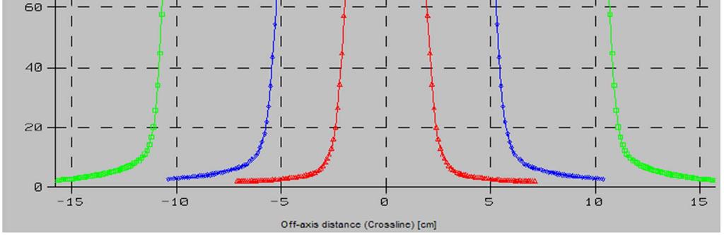
16 Off-axis or cross-beam beam profiles 16
17 Field size Geometric or nominal field size is: Indicated by the optical light field of the treatment machine. Usually defined as the separation between the 50% dose level points on the beam profile measured at the depth of dose maximum z max (dosimetric field size) 17


18 Penumbra The total penumbra is referred to as the physical penumbra and consists of three components: Geometric penumbra results from the finite source size. Scatter penumbra results from in-patient photon scatter originating in the open field. Transmission penumbra results from beam transmitted through the collimation device. 18


19 Flatness & Symmetry 19
20 Isodose chart & isodose curves An isodose chart for a given single beam consists of a family of isodose curves usually drawn at regular increments of PDD. Two normalization conventions are in use: For SSD set-ups, all isodose values are normalized to 100% at point of dose maximum on the central beam axis. For SAD set-ups, the isodose values are normalized to 100% at the isocentre 20
21 Normalization at dose maximum For SSD set-ups, all isodose values are normalized to 100% at point P on the central beam axis (point of dose maximum at depth z max ). 21
22 Normalization at isocentre For SAD set-ups, the isodose values are normalized to 100% at the isocentre. 22


23 Different type of normalization Different normalizations for a single 18 MV photon beam incident on a patient contour Isodose curves for a fixed SSD beam normalized at depth of dose maximum Isodose curves for an isocentric beam normalized at the isocenter 23
24 Isodose curves are affected by Beam quality Source size Beam collimation Field size Source-skin distance Source-collimator distance 24

25 Isodose curves for different energies Isodose distributions for various photon radiation beams: orthovoltage x rays, cobalt-60 gamma rays, 4 MV x rays, 10 MV x rays 25

26 Ears in an isodose chart: Have you ever noticed? From: Dr. Palta, Univ of Florida 26
27 Ears in an isodose chart: Have you ever noticed? Contaminant electrons contribute to dose outside the field at shallow depths. The magnitude and extent of the dose outside the geometric edge of a field at shallow depths increases with beam energy Does your TPS model this phenomenon? From: Dr. Palta, Univ of Florida 27
28 Corrections for contour irregularities Measured dose distributions apply to a flat radiation beam incident on a flat homogeneous water phantom. To relate such measurements to the actual dose distribution in a patient, corrections for irregular surface and tissue inhomogeneities have to be applied. Three methods for contour correction are used: (1) the (manual) isodose shift method; (2) the effective attenuation coefficient method; (3) the TAR method. 28
29 Corrections for contour irregularities Grid lines are drawn parallel to the central beam axis all across the field. The tissue deficit (or excess) h is the difference between the SSD along a gridline and the SSD on the central axis. k is an energy dependent parameter given in the next slide. The isodose distribution for a flat phantom is aligned with the SSD central axis on the patient contour. For each gridline, the overlaid isodose distribution is shifted up (or down) such that the overlaid SSD is at a point k h above (or below) the central axis SSD. (1) Manual isodose shift method 29
30 Corrections for contour irregularities Parameter k used in the isodose shift method Photon energy (MV) k (approximate) < Co >
31 Corrections for contour irregularities (2) Effective attenuation coefficient method The correction factor is determined from the attenuation factor exp(-µx), where x is the depth of missing tissue above the calculation point, and µ is the linear attenuation coefficient of tissue for a given energy. For simplicity the factors are usually pre-calculated and supplied in graphical or tabular form. 31
32 Corrections for contour irregularities (3) TAR method The tissue-air ratio (TAR) correction method is also based on the attenuation law, but takes the depth of the calculation point and the field size into account. Generally, the correction factor C F as a function of depth z, thickness of missing tissue h, and field size f, is given by: C F TAR( z h, f ) = TAR( z, f ) TMRs / TPRs also can be used in place of TAR 32
33 Corrections for tissue inhomogeneities Radiation beams used in patient treatment traverse various tissues that may differ from water in density and atomic number. This may result in isodose distributions that differ significantly from those obtained with water phantoms. The effects of inhomogeneities on the dose distributions depend upon: Amount, density and atomic number of the inhomogeneity. Quality of the radiation beam. 33
 beyond the inhomogeneity: TAR method Power law TAR method Equivalent TAR method Isodose shift method")
34 Corrections for tissue inhomogeneities Four empirical methods have been developed for correcting the water phantom dose to obtain the dose at points P 3 in region (3) beyond the inhomogeneity: TAR method Power law TAR method Equivalent TAR method Isodose shift method 34
35 Best way to account for inhomogeneities Model based algorithms Convolution-superposition method Monte Carlo method 35
36 General considerations for photon beams Almost a dogma in external beam radiotherapy: Successful radiotherapy requires a uniform dose distribution within the target (tumor). External photon beam radiotherapy is usually carried out with multiple radiation beams in order to achieve a uniform dose distribution inside the target volume and a dose as low as possible in healthy tissues surrounding the target. 36
.")
37 Criteria of a uniform dose distribution within the target Recommendations regarding dose uniformity, prescribing, recording, and reporting photon beam therapy are set forth by the International Commission on Radiation Units and Measurements (ICRU). The ICRU report 50 recommends a target dose uniformity within +7% and 5% relative to the dose delivered to a well defined prescription point within the target. 37
38 Methods of beam setup Photon beam radiotherapy is carried out under two setup conventions constant Source-Surface Distance (SSD technique) isocentric setup with a constant Source- Axis Distance (SAD technique). 38


39 SSD technique The distance from the source to the surface of the patient is kept constant for all beams. 39


40 SAD technique The center of the target volume is placed at the machine isocenter, i.e. the distance to the target point is kept constant for all beams. Note: In contrast to SSD technique, the SAD technique requires no adjustment of the patient setup when turning the gantry to the next field. 40
41 SSD vs. SAD technique: Which is better? There is little difference between fixed SSD techniques and isocentric (SAD) techniques with respect to the dose: Fixed SSD arrangements are usually at a greater SSD than isocentric beams because the machine isocenter is on the patient skin. They have therefore a slightly higher PDD at depth. Additionally, beam divergence is smaller with SSD due to the larger distance. 41


42 SSD vs. SAD technique: Which is better? These dosimetric advantages of SSD technique are small. With the exception of very large fields exceeding 40x40 cm 2, the advantages of using a single set-up point (i.e., the isocenter) greatly outweigh the dosimetric advantage of SSD beams 42
43 Dose specification Parameters to characterize the dose distribution within a volume and to specify the dose are: Minimum target dose Maximum target dose Mean target dose A reference dose at a representative point within the volume The ICRU has given recommendations for the selection of a representative point (the so-called ICRU reference point). 43
44 Dose specification The ICRU reference dose point is located at a point chosen to represent the delivered dose using the following criteria: The point should be located in a region where the dose can be calculated accurately (i.e., no build-up or steep gradients). The point should be in the central part of the PTV. For multiple fields, the isocenter (or beam intersection point) is recommended as the ICRU reference point. 44

 point is located at the")
45 Dose specification ICRU reference point for multiple fields Example for a 3 field prostate boost treatment with an isocentric technique The ICRU (reference) point is located at the isocenter 45
46 ICRU Reference point Specific recommendations are made with regard to the position of the ICRU (reference) point for particular beam combinations: For single beam: the point on central axis at the center of the target volume. For parallel-opposed equally weighted beams: the point on the central axis midway between the beam entrance points. For parallel-opposed unequally weighted beams: the point on the central axis at the centre of the target volume. For other combinations of intersecting beams: the point at the intersection of the central axes (insofar as there is no dose gradient at this point). 46
47 Beam combinations and clinical application Single photon beams are of limited use in the treatment of deep-seated tumors, since they give a higher dose near the entrance at the depth of dose maximum than at depth. 47

48 Beam combinations and clinical application Single fields are often used for palliative treatments or for relatively superficial lesions (depth < 5-10 cm, depending on the beam energy). For deeper lesions, a combination of two or more photon beams is usually required to concentrate the dose in the target volume and spare the tissues surrounding the target as much as possible. 48
49 Beam combinations and clinical application Normalization Dose distributions for multiple beams can be normalized to 100% just as for single beams: at z max for each beam, at isocenter for each beam. This implies that each beam is equally weighted. 49
50 Beam combinations and clinical application Weighting and normalization A beam weighting may additionally applied at the normalization point for the given beam. Example: Two beams with z max normalization weighted as 100 : 50% will show one beam with the 100% isodose at z max and the other one with 50% at z max. A similar isocentric weighted beam pair would show the 150% isodose at the isocenter. 50
51 Beam combinations and clinical application Parallel opposed beams Equally weighted Example: A parallel-opposed beam pair is incident on a patient. Note the large rectangular area of relatively uniform dose (<15% variation). The isodoses have been normalized to 100% at the isocenter. This beam combination is well suited to a large variety of treatment sites (e.g., lung, brain, head and neck). 51
52 Beam combinations and clinical application Parallel opposed beams Unequally weighted When? Target volume is one sided, but at a larger depth Single beam will give very high entry dose Equally weighted opposing beams will give high dose throughout the volume Give more weight to the beam from target side & less to the other Remember, it is NOT a magic solution Isocenter can be at mid-plane or at center of tumor ratio of weights will differ 52
53 Beam combinations and clinical application Parallel opposed beams Equally weighted Weight - 100:100 at iso At iso, it is now 200% Tumor is covered by 187% What does this mean? Beam 1 Beam Tumor 187 cgy 100 cgy 100 cgy Tumor 300 cgy We need to deliver this cgy at the iso of each beam 53

54 Beam combinations and clinical application Parallel opposed beams Unequally weighted Weight - 100:200 at iso (AP:PA) At iso, it is now 300% Tumor is covered by 282% What does this mean? Beam 1 Beam Tumor 282 cgy 100 cgy 200 cgy Tumor 300 cgy We need to deliver cgy & cgy at the iso of AP & PA beams respectively 54


55 Beam combinations and clinical application Multiple co-planar beams Multiple coplanar beams allows for a higher dose in the beam intersection region. Two examples: 4-field box 3-field technique using wedges 55


56 Beam combinations and clinical application Multiple co-planar beams 4 field box A 4-field box allows for a very high dose to be delivered at the intersection of the beams. 56

57 Beam combinations and clinical application Multiple co-planar beams 3-field technique using wedges A 3-field technique requires the use of wedges to achieve a similar result. Note that the latter can produce significant hot spots near the entrance of the wedged beams and well outside the targeted area

58 Beam combinations and clinical application 3-field technique using wedges Equally weighted Weight 100:100:100 at iso At iso it is now 300% Target covered by 290% Beam 1 Beam 2 Beam 3 Target 290 cgy 100 cgy 100 cgy 100 cgy 290 Target 200 cgy We have to deliver 69 cgy at the iso of each beam Note: For the wedged beams, we need to take into account the wedge attenuation factor (transmission factor) while calculating time or MUs 58
59 Beam combinations and clinical application 3-field technique using wedges Unequally weighted Weight 60:110:120 at iso (AP:RL:LL) At iso it is now 290% Target covered by 270% Beam 1 Beam 2 Beam 3 Target 270 cgy 60 cgy 110 cgy 120 cgy 270 Target 200 cgy We have to deliver 44.4 cgy, 81.5 cgy & 88.9 cgy at the iso of AP, RL and LL beams respectively. 59
60 Normalization Weight 60:110:120 at iso (AP:RL:LL) At iso it is now 290% Target covered by 270% We normalize 290% to 100% Target is covered by 270% or [100/290]*[270] = 93.1% The question is: are you going to prescribe your dose to 100%? or to 93.1%? Prescribing at 100% - tumor receives a minimum dose of 93.1% of your prescription dose Prescribing at 93.1% - tumor receives your FULL prescription dose, but some part is overdosed by 7.4% (or even more)


61
62 62
Dose Distributions. Purpose. Isodose distributions. To familiarize the resident with dose distributions and the factors that affect them
 Dose Distributions George Starkschall, Ph.D. Department of Radiation Physics U.T. M.D. Anderson Cancer Center Purpose To familiarize the resident with dose distributions and the factors that affect them
Photon beam dose distributions in 2D
 Photon beam dose distributions in 2D Sastry Vedam PhD DABR Introduction to Medical Physics III: Therapy Spring 2014 Acknowledgments! Narayan Sahoo PhD! Richard G Lane (Late) PhD 1 Overview! Evaluation
A SYSTEM OF DOSIMETRIC CALCULATIONS
 A SYSTEM OF DOSIMETRIC CALCULATIONS INTRODUCTION Dose calculation based on PDD and TAR have Limitations The dependence of PDD on SSD Not suitable for isocentric techniques TAR and SAR does not depend on
EXTERNAL PHOTON BEAMS: PHYSICAL ASPECTS
 EXTERNAL PHOTON BEAMS: PHYSICAL ASPECTS E.B. PODGORSAK Department of Medical Physics, McGill University Health Centre, Montreal, Quebec, Canada 6.1. INTRODUCTION Radiotherapy procedures fall into two main
Basics of treatment planning II
 Basics of treatment planning II Sastry Vedam PhD DABR Introduction to Medical Physics III: Therapy Spring 2015 Dose calculation algorithms! Correction based! Model based 1 Dose calculation algorithms!
Proton dose calculation algorithms and configuration data
 Proton dose calculation algorithms and configuration data Barbara Schaffner PTCOG 46 Educational workshop in Wanjie, 20. May 2007 VARIAN Medical Systems Agenda Broad beam algorithms Concept of pencil beam
Machine and Physics Data Guide
 WWW..COM Machine and Physics Data Guide STANDARD IMAGING, INC. 3120 Deming Way Middleton, WI 53562-1461 May / 2008 2008 Standard Imaging, Inc. TEL 800.261.4446 TEL 608.831.0025 FAX 608.831.2202 www.standardimaging.com
Transitioning from pencil beam to Monte Carlo for electron dose calculations
 Transitioning from pencil beam to Monte Carlo for electron dose calculations Jessie Huang-Vredevoogd (jyhuang4@wisc.edu) University of Wisconsin NCC AAPM October 12, 2019 1 Topics to cover Background RayStation
CLINICAL ASPECTS OF COMPACT GANTRY DESIGNS
 CLINICAL ASPECTS OF COMPACT GANTRY DESIGNS J. Heese, J. Wulff, A. Winnebeck, A. Huggins, M. Schillo VARIAN PARTICLE THERAPY JUERGEN HEESE New gantry developments Viewpoint from user and vendor perspective
An Investigation of a Model of Percentage Depth Dose for Irregularly Shaped Fields
 Int. J. Cancer (Radiat. Oncol. Invest): 96, 140 145 (2001) 2001 Wiley-Liss, Inc. Publication of the International Union Against Cancer An Investigation of a Model of Percentage Depth Dose for Irregularly
How would, or how does, the patient position (chin extended) affect your beam arrangement?
 affect your beam arrangement?") 1 Megan Sullivan Clinical Practicum II Parotid Lab July 29, 2016 PLAN 1: IPSILATERAL WEDGE PAIR TECHNIQUE The ipsilateral wedge pair technique consisted of an anterior oblique field at 45 degrees and a
1 Megan Sullivan Clinical Practicum II Parotid Lab July 29, 2016 PLAN 1: IPSILATERAL WEDGE PAIR TECHNIQUE The ipsilateral wedge pair technique consisted of an anterior oblique field at 45 degrees and a
Tomotherapy Physics. Machine Twinning and Quality Assurance. Emilie Soisson, MS
 Tomotherapy Physics Machine Twinning and Quality Assurance Emilie Soisson, MS Tomotherapy at UW- Madison Treating for nearly 5 years Up to ~45 patients a day on 2 tomo units Units twinned to facilitate
Investigation of tilted dose kernels for portal dose prediction in a-si electronic portal imagers
 Investigation of tilted dose kernels for portal dose prediction in a-si electronic portal imagers Krista Chytyk MSc student Supervisor: Dr. Boyd McCurdy Introduction The objective of cancer radiotherapy
NEW METHOD OF COLLECTING OUTPUT FACTORS FOR COMMISSIONING LINEAR ACCELERATORS WITH SPECIAL EMPHASIS
 NEW METHOD OF COLLECTING OUTPUT FACTORS FOR COMMISSIONING LINEAR ACCELERATORS WITH SPECIAL EMPHASIS ON SMALL FIELDS AND INTENSITY MODULATED RADIATION THERAPY by Cindy D. Smith A Thesis Submitted to the
A secondary monitor unit calculation algorithm using superposition of symmetric, open fields for IMRT plans
 Louisiana State University LSU Digital Commons LSU Master's Theses Graduate School 2013 A secondary monitor unit calculation algorithm using superposition of symmetric, open fields for IMRT plans Adam
The MSKCC Approach to IMRT. Outline
 The MSKCC Approach to IMRT Spiridon V. Spirou, PhD Department of Medical Physics Memorial Sloan-Kettering Cancer Center New York, NY Outline Optimization Field splitting Delivery Independent verification
IMSURE QA SOFTWARE FAST, PRECISE QA SOFTWARE
 QA SOFTWARE FAST, PRECISE Software for accurate and independent verification of monitor units, dose, and overall validity of standard, IMRT, VMAT, SRS and brachytherapy plans no film, no phantoms, no linac
Analysis of Radiation Transport through Multileaf Collimators Using BEAMnrc Code
 American Journal of Biomedical Engineering 216, 6(4): 124-131 DOI: 1.5923/j.ajbe.21664.3 Analysis of Radiation Transport through Multileaf Collimators Using BEAMnrc Code Ankit Kajaria 1,*, Neeraj Sharma
IAEA-TECDOC-1583 Commissioning of Radiotherapy Treatment Planning Systems: Testing for Typical External Beam Treatment Techniques
 IAEA-TECDOC-1583 Commissioning of Radiotherapy Treatment Planning Systems: Testing for Typical External Beam Treatment Techniques Report of the Coordinated Research Project (CRP) on Development of Procedures
Acknowledgments. Ping Xia, Ph.D., UCSF. Pam Akazawa, CMD, UCSF. Cynthia Chuang, Ph.D., UCSF
 Page 1 Quality Assurance of IMRT Delivery Systems - Siemens Lynn J. Verhey, Ph.D. Professor and Vice-Chair UCSF Dept. of Radiation Oncology AAPM 22 Annual Meeting, Montreal Acknowledgments Ping Xia, Ph.D.,
4 Measurement. and Analysis. 4.1 Overview and Underlying Principles 4-1
 Measurement and Analysis.1 Overview and Underlying Principles.1.1 Introductory Remarks The physics and setup for film dosimetry have been described in the previous chapters. The measurement setup for IMRT
Dose Calculations: Where and How to Calculate Dose. Allen Holder Trinity University.
 Dose Calculations: Where and How to Calculate Dose Trinity University www.trinity.edu/aholder R. Acosta, W. Brick, A. Hanna, D. Lara, G. McQuilen, D. Nevin, P. Uhlig and B. Slater Dose Calculations - Why
A DOSIMETRIC MODEL FOR SMALL-FIELD ELECTRON RADIATION THERAPY A CREATIVE PROJECT (3 SEMESTER HOURS) SUBMITTED TO THE GRADUATE SCHOOL
 SUBMITTED TO THE GRADUATE SCHOOL") A DOSIMETRIC MODEL FOR SMALL-FIELD ELECTRON RADIATION THERAPY A CREATIVE PROJECT (3 SEMESTER HOURS) SUBMITTED TO THE GRADUATE SCHOOL IN PARTIAL FULFILLMENT OF THE REQUIREMENTS FOR THE DEGREE MASTER OF
A DOSIMETRIC MODEL FOR SMALL-FIELD ELECTRON RADIATION THERAPY A CREATIVE PROJECT (3 SEMESTER HOURS) SUBMITTED TO THE GRADUATE SCHOOL IN PARTIAL FULFILLMENT OF THE REQUIREMENTS FOR THE DEGREE MASTER OF
Photon Dose Algorithms and Physics Data Modeling in modern RTP
 Photon Dose Algorithms and Physics Data Modeling in modern RTP Niko Papanikolaou, PhD Professor and Director of Medical Physics University of Texas Health Science Center of San Antonio Cancer Therapy &
A software tool for the quantitative evaluation of 3D dose calculation algorithms
 A software tool for the quantitative evaluation of 3D dose calculation algorithms William B. Harms, Sr., Daniel A. Low, John W. Wong, a) and James A. Purdy Washington University School of Medicine, Mallinckrodt
Hugues Mailleux Medical Physics Department Institut Paoli-Calmettes Marseille France. Sunday 17 July 2016
 Hugues Mailleux Medical Physics Department Institut Paoli-Calmettes Marseille France Sunday 17 July 2016 AGENDA 1. Introduction 2. Material 3. Optimization process 4. Results 5. Comments 6. Conclusion
FAST, precise. qa software
 qa software FAST, precise Software for accurate and independent verification of monitor units, dose, and overall validity of standard, IMRT, rotational or brachytherapy plans no film, no phantoms, no linac
Clinical implementation of photon beam flatness measurements to verify beam quality
 JOURNAL OF APPLIED CLINICAL MEDICAL PHYSICS, VOLUME 16, NUMBER 6, 2015 Clinical implementation of photon beam flatness measurements to verify beam quality Simon Goodall, a Nicholas Harding, Jake Simpson,
IMRT site-specific procedure: Prostate (CHHiP)
") IMRT site-specific procedure: Prostate (CHHiP) Scope: To provide site specific instructions for the planning of CHHIP IMRT patients Responsibilities: Radiotherapy Physicists, HPC Registered Therapy Radiographers
IMRT site-specific procedure: Prostate (CHHiP) Scope: To provide site specific instructions for the planning of CHHIP IMRT patients Responsibilities: Radiotherapy Physicists, HPC Registered Therapy Radiographers
Electron Dose Kernels (EDK) for Secondary Particle Transport in Deterministic Simulations
 for Secondary Particle Transport in Deterministic Simulations") Electron Dose Kernels (EDK) for Secondary Particle Transport in Deterministic Simulations A. Al-Basheer, G. Sjoden, M. Ghita Computational Medical Physics Team Nuclear & Radiological Engineering University
Electron Dose Kernels (EDK) for Secondary Particle Transport in Deterministic Simulations A. Al-Basheer, G. Sjoden, M. Ghita Computational Medical Physics Team Nuclear & Radiological Engineering University
THE SIMULATION OF THE 4 MV VARIAN LINAC WITH EXPERIMENTAL VALIDATION
 2007 International Nuclear Atlantic Conference - INAC 2007 Santos, SP, Brazil, September 30 to October 5, 2007 ASSOCIAÇÃO BRASILEIRA DE ENERGIA NUCLEAR - ABEN ISBN: 978-85-99141-02-1 THE SIMULATION OF
Chapter 9 Field Shaping: Scanning Beam
 Chapter 9 Field Shaping: Scanning Beam X. Ronald Zhu, Ph.D. Department of Radiation Physics M. D. Anderson Cancer Center Houston, TX June 14-18, 2015 AAPM - Summer School 2015, Colorado Spring Acknowledgement
Effects of the difference in tube voltage of the CT scanner on. dose calculation
 Effects of the difference in tube voltage of the CT scanner on dose calculation Dong Joo Rhee, Sung-woo Kim, Dong Hyeok Jeong Medical and Radiological Physics Laboratory, Dongnam Institute of Radiological
IMRT and VMAT Patient Specific QA Using 2D and 3D Detector Arrays
 IMRT and VMAT Patient Specific QA Using 2D and 3D Detector Arrays Sotiri Stathakis Outline Why IMRT/VMAT QA AAPM TG218 UPDATE Tolerance Limits and Methodologies for IMRT Verification QA Common sources
CHAPTER 9 INFLUENCE OF SMOOTHING ALGORITHMS IN MONTE CARLO DOSE CALCULATIONS OF CYBERKNIFE TREATMENT PLANS: A LUNG PHANTOM STUDY
 148 CHAPTER 9 INFLUENCE OF SMOOTHING ALGORITHMS IN MONTE CARLO DOSE CALCULATIONS OF CYBERKNIFE TREATMENT PLANS: A LUNG PHANTOM STUDY 9.1 INTRODUCTION 9.1.1 Dose Calculation Algorithms Dose calculation
VALIDATION OF A MONTE CARLO DOSE CALCULATION ALGORITHM FOR CLINICAL ELECTRON BEAMS IN THE PRESENCE OF PHANTOMS WITH COMPLEX HETEROGENEITIES
 VALIDATION OF A MONTE CARLO DOSE CALCULATION ALGORITHM FOR CLINICAL ELECTRON BEAMS IN THE PRESENCE OF PHANTOMS WITH COMPLEX HETEROGENEITIES by Shayla Landfair Enright A Thesis Submitted to the Faculty
Monte Carlo methods in proton beam radiation therapy. Harald Paganetti
 Monte Carlo methods in proton beam radiation therapy Harald Paganetti Introduction: Proton Physics Electromagnetic energy loss of protons Distal distribution Dose [%] 120 100 80 60 40 p e p Ionization
MCNP4C3-BASED SIMULATION OF A MEDICAL LINEAR ACCELERATOR
 Computational Medical Physics Working Group Workshop II, Sep 3 Oct 3, 7 University of Florida (UF), Gainesville, Florida USA on CD-ROM, American Nuclear Society, LaGrange Park, IL (7) MCNP4C3-BASED SIMULATION
Acceptance Testing and Commissioning of Monte Carlo Dose Calculation Systems. Bruce Curran University of Michigan Medical Center Ann Arbor, MI
 Acceptance Testing and Commissioning of Monte Carlo Dose Calculation Systems Bruce Curran University of Michigan Medical Center Ann Arbor, MI Disclosure Some of the work discussed in this talk was supported
Influence of electron density spatial distribution and X-ray beam quality during CT simulation on dose calculation accuracy
 JOURNAL OF APPLIED CLINICAL MEDICAL PHYSICS, VOLUME 12, NUMBER 3, summer 2011 Influence of electron density spatial distribution and X-ray beam quality during CT simulation on dose calculation accuracy
The IORT Treatment Planning System. radiance. GMV, 2012 Property of GMV All rights reserved
 The IORT Treatment Planning System radiance Property of GMV All rights reserved WHY RADIANCE? JUSTIFICATION Property of GMV All rights reserved ADVANTAGES OF IORT PRECISION: RT guided by direct vision.
Monte Carlo Simulation for Neptun 10 PC Medical Linear Accelerator and Calculations of Electron Beam Parameters
 Monte Carlo Simulation for Neptun 1 PC Medical Linear Accelerator and Calculations of Electron Beam Parameters M.T. Bahreyni Toossi a, M. Momen Nezhad b, S.M. Hashemi a a Medical Physics Research Center,
Assesing multileaf collimator effect on the build-up region using Monte Carlo method
 Pol J Med Phys Eng. 2008;14(3):163-182. PL ISSN 1425-4689 doi: 10.2478/v10013-008-0014-0 website: http://www.pjmpe.waw.pl M. Zarza Moreno 1, 2, N. Teixeira 3, 4, A. P. Jesus 1, 2, G. Mora 1 Assesing multileaf
Development a simple point source model for Elekta SL-25 linear accelerator using MCNP4C Monte Carlo code
 Iran. J. Radiat. Res., 2006; 4 (1): 7-14 Development a simple point source model for Elekta SL-25 linear accelerator using MCNP4C Monte Carlo code. Mesbahi * Department of Medical Physics, Medical School,
Volumetric Modulated Arc Therapy - Clinical Implementation. Outline. Acknowledgement. History of VMAT. IMAT Basics of IMAT
 Volumetric Modulated Arc Therapy - Clinical Implementation Daliang Cao, PhD, DABR Swedish Cancer Institute, Seattle, WA Acknowledgement David M. Shepard, Ph.D. Muhammad K. N. Afghan, Ph.D. Fan Chen, Ph.D.
Monitor Unit (MU) Calculation
 Calculation") Monitor Unit (MU) Calculation Timothy C. Zhu 1, Haibo Lin 1, and JiaJian Shen 2 1 University of Pennsylvania, Philadelphia, PA 2 Mayo Clinic, Phoenix, AZ Introduction Pencil-beam based dose/mu algorithms
Monitor Unit (MU) Calculation Timothy C. Zhu 1, Haibo Lin 1, and JiaJian Shen 2 1 University of Pennsylvania, Philadelphia, PA 2 Mayo Clinic, Phoenix, AZ Introduction Pencil-beam based dose/mu algorithms
Dynalog data tool for IMRT plan verification
 Dynalog data tool for IMRT plan verification Poster No.: R-0051 Congress: 2014 CSM Type: Scientific Exhibit Authors: V. Sashin; FOOTSCRAY/AU Keywords: Computer applications, Radiation physics, Experimental,
Implementation of the EGSnrc / BEAMnrc Monte Carlo code - Application to medical accelerator SATURNE43
 International Journal of Innovation and Applied Studies ISSN 2028-9324 Vol. 6 No. 3 July 2014, pp. 635-641 2014 Innovative Space of Scientific Research Journals http://www.ijias.issr-journals.org/ Implementation
7/31/2011. Learning Objective. Video Positioning. 3D Surface Imaging by VisionRT
 CLINICAL COMMISSIONING AND ACCEPTANCE TESTING OF A 3D SURFACE MATCHING SYSTEM Hania Al-Hallaq, Ph.D. Assistant Professor Radiation Oncology The University of Chicago Learning Objective Describe acceptance
C a t p h a n / T h e P h a n t o m L a b o r a t o r y
 C a t p h a n 5 0 0 / 6 0 0 T h e P h a n t o m L a b o r a t o r y C a t p h a n 5 0 0 / 6 0 0 Internationally recognized for measuring the maximum obtainable performance of axial, spiral and multi-slice
8/4/2016. Emerging Linac based SRS/SBRT Technologies with Modulated Arc Delivery. Disclosure. Introduction: Treatment delivery techniques
 Emerging Linac based SRS/SBRT Technologies with Modulated Arc Delivery Lei Ren, Ph.D. Duke University Medical Center 2016 AAPM 58 th annual meeting, Educational Course, Therapy Track Disclosure I have
New Technology in Radiation Oncology. James E. Gaiser, Ph.D. DABR Physics and Computer Planning Charlotte, NC
 New Technology in Radiation Oncology James E. Gaiser, Ph.D. DABR Physics and Computer Planning Charlotte, NC Technology s s everywhere From the imaging chain To the planning system To the linac To QA..it..it
Automated Image Analysis Software for Quality Assurance of a Radiotherapy CT Simulator
 Automated Image Analysis Software for Quality Assurance of a Radiotherapy CT Simulator Andrew J Reilly Imaging Physicist Oncology Physics Edinburgh Cancer Centre Western General Hospital EDINBURGH EH4
Data. ModuLeaf Mini Multileaf Collimator Precision Beam Shaping for Advanced Radiotherapy
 Data ModuLeaf Mini Multileaf Collimator Precision Beam Shaping for Advanced Radiotherapy ModuLeaf Mini Multileaf Collimator Precision Beam Shaping for Advanced Radiotherapy The ModuLeaf Mini Multileaf
Follow this and additional works at:
 The University of Toledo The University of Toledo Digital Repository Theses and Dissertations 2010 Implementation of the Dosimetry Check software package in computing 3D patient exit dose through generation
ICARO Vienna April Implementing 3D conformal radiotherapy and IMRT in clinical practice: Recommendations of IAEA- TECDOC-1588
 ICARO Vienna April 27-29 2009 Implementing 3D conformal radiotherapy and IMRT in clinical practice: Recommendations of IAEA- TECDOC-1588 M. Saiful Huq, Ph.D., Professor and Director, Dept. of Radiation
Raising the Bar in IMRT QA
 MapCHECK 2TM Raising the Bar in IMRT QA The leader in quick and precise measurement of modulated radiotherapy beams Benefits Proven solution for film-less rotational delivery and IMRT QA - More than 1500
Integrated proton-photon treatment planning
 Pinnacle 3 Proton Planning Integrated proton-photon treatment planning Philips Pinnacle 3 Proton Planning specifications Pinnacle 3 Proton Planning is designed to simplify treatment planning for proton
Accuracy of treatment planning calculations for conformal radiotherapy van 't Veld, Aart Adeodatus
 University of Groningen Accuracy of treatment planning calculations for conformal radiotherapy van 't Veld, Aart Adeodatus IMPORTANT NOTE: You are advised to consult the publisher's version (publisher's
DOSE-CALCULATION ALGORITHMS USED IN RADIATION TREATMENT PLANNING MANUEL SALGADO FERNÁNDEZ
 Hospital do Meixoeiro DOSE-CALCULATION ALGORITHMS USED IN RADIATION TREATMENT PLANNING MANUEL SALGADO FERNÁNDEZ Servicio de Radíofísica y Protección Radiológica Galaria. Hospital do Meixoeiro. Av. Meixoeiro
REAL-TIME ADAPTIVITY IN HEAD-AND-NECK AND LUNG CANCER RADIOTHERAPY IN A GPU ENVIRONMENT
 REAL-TIME ADAPTIVITY IN HEAD-AND-NECK AND LUNG CANCER RADIOTHERAPY IN A GPU ENVIRONMENT Anand P Santhanam Assistant Professor, Department of Radiation Oncology OUTLINE Adaptive radiotherapy for head and
Michael Speiser, Ph.D.
 IMPROVED CT-BASED VOXEL PHANTOM GENERATION FOR MCNP MONTE CARLO Michael Speiser, Ph.D. Department of Radiation Oncology UT Southwestern Medical Center Dallas, TX September 1 st, 2012 CMPWG Workshop Medical
Creating a Knowledge Based Model using RapidPlan TM : The Henry Ford Experience
 DVH Estimates Creating a Knowledge Based Model using RapidPlan TM : The Henry Ford Experience Karen Chin Snyder, MS, DABR AAMD Region V Meeting October 4, 2014 Disclosures The Department of Radiation Oncology
I Introduction 2. IV Relative dose in electron and photon beams 26 IV.A Dose and kerma per unit incident fluence... 27
 Notes on the structure of radiotherapy depth-dose distributions David W O Rogers Carleton Laboratory for Radiotherapy Physics Physics Department, Carleton University, Ottawa, Canada drogers at physics.carleton.ca
DOSIMETRY/ RADIATION THERAPY TERMS
 DOSIMETRY/ RADIATION THERAPY TERMS BENJAMIN RODRIGUEZ CLINICAL TRAINING RTH 290 1. Digital Reconstructed Radiograph (DRR) Is based on acquired CT information, these are images that render a beam s eye
MapCHECK 2 & 3DVH. The Gold Standard for 2D Arrays
 MapCHECK 2 & 3DVH The Gold Standard for 2D Arrays Your Most Valuable QA and Dosimetry Tools THE GOLD STANDARD FOR 2D ARRAYS The MapCHECK 2 is the world s most selected independent 2D measurement array.
ROBUST OPTIMIZATION THE END OF PTV AND THE BEGINNING OF SMART DOSE CLOUD. Moe Siddiqui, April 08, 2017
 ROBUST OPTIMIZATION THE END OF PTV AND THE BEGINNING OF SMART DOSE CLOUD Moe Siddiqui, April 08, 2017 Agenda Background IRCU 50 - Disclaimer - Uncertainties Robust optimization Use Cases Lung Robust 4D
MapCHECK 2 & 3DVH The Gold Standard for 2D Arrays
 MapCHECK 2 & 3DVH The Gold Standard for 2D Arrays Your Most Valuable QA and Dosimetry Tools THE GOLD STANDARD FOR 2D ARRAYS The MapCHECK 2 is the world s most selected independent 2D measurement array.
Use of Monte Carlo modelling in radiotherapy linac design. David Roberts, PhD Senior Physicist Elekta
 Use of Monte Carlo modelling in radiotherapy linac design David Roberts, PhD Senior Physicist Elekta Contents Overview of Elekta What we do Where we use Monte Carlo Codes and resources Example : Agility
Calculating percent depth dose with the electron pencilbeam redefinition algorithm
 JOURNAL OF APPLIED CLINICAL MEDICAL PHYSICS, VOLUME 8, NUMBER 2, SPRING 2007 Calculating percent depth dose with the electron pencilbeam redefinition algorithm Michael J. Price, 1,2,a Kenneth R. Hogstrom,
Preface. Med. Phys. 35(9), , Mechanical QA. Radiation Survey Mechanical tests Light radiation Table, Collimator, Gantry Jaws.
, , Mechanical QA. Radiation Survey Mechanical tests Light radiation Table, Collimator, Gantry Jaws.") AAPM-SAM-2012-Das (1) Beam Data Collection and Commissioning for Linear Accelerators: Technical Considerations and Recommendations Preface Indra J. Das, PhD, FAAPM, FACR, FASTRO Department of Radiation
AAPM-SAM-2012-Das (1) Beam Data Collection and Commissioning for Linear Accelerators: Technical Considerations and Recommendations Preface Indra J. Das, PhD, FAAPM, FACR, FASTRO Department of Radiation
Disclosure. Outline. Acknowledgments. Ping Xia, Ph.D., Page 1. LINAC and MLC QA for IMRT. Received research support from Siemens Medical Solutions
 LINAC and MLC QA for IMRT Ping Xia, Ph.D., Department of Radiation Oncology Disclosure Received research support from Siemens Medical Solutions University of California San Francisco Therapy Series (SAM)
Monaco Concepts and IMRT / VMAT Planning LTAMON0003 / 3.0
 and IMRT / VMAT Planning LTAMON0003 / 3.0 and Planning Objectives By the end of this presentation you can: Describe the cost functions in Monaco and recognize their application in building a successful
UNCOMPROMISING QUALITY
 ION CHAMBERS UNCOMPROMISING QUALITY Designed with over 30 years of scientific integrity for a broad range of dosimetry measurements in diverse radiation beams Farmer-type Chambers For absolute dosimetry
Design and performance characteristics of a Cone Beam CT system for Leksell Gamma Knife Icon
 Design and performance characteristics of a Cone Beam CT system for Leksell Gamma Knife Icon WHITE PAPER Introduction Introducing an image guidance system based on Cone Beam CT (CBCT) and a mask immobilization
On compensator design for photon beam intensity-modulated conformal therapy
 On compensator design for photon beam intensity-modulated conformal therapy Steve B. Jiang a) and Komanduri M. Ayyangar Department of Radiation Therapy, Medical College of Ohio, 3000 Arlington Avenue,
S. Guru Prasad, Ph.D., DABR
 PURPOSE S. Guru Prasad, Ph.D., DABR Director of Medical Physics IAEA Consultant NorthShore University Health System and University of Chicago, Pritzker School of Medicine Current TPS utilize more information
Hidenobu Tachibana The Cancer Institute Hospital of JFCR, Radiology Dept. The Cancer Institute of JFCR, Physics Dept.
 2-D D Dose-CT Mapping in Geant4 Hidenobu Tachibana The Cancer Institute Hospital of JFCR, Radiology Dept. The Cancer Institute of JFCR, Physics Dept. Table of Contents Background & Purpose Materials Methods
THE WIRELESS PHANTOM PERFORM ACCURATE PATIENT QA IN LESS TIME THAN EVER!
 THE WIRELESS PHANTOM PERFORM ACCURATE PATIENT QA IN LESS TIME THAN EVER! Confidence in complex treatments Modern radiation therapy uses complex plans with techniques such as IMRT, VMAT and Tomotherapy.
Ch. 4 Physical Principles of CT
 Ch. 4 Physical Principles of CT CLRS 408: Intro to CT Department of Radiation Sciences Review: Why CT? Solution for radiography/tomography limitations Superimposition of structures Distinguishing between
2D DOSE MEASUREMENT USING A FLAT PANEL EPID
 2D DOSE MEASUREMENT USING A FLAT PANEL EPID by Seng Boh Lim B.A.Sc. (Hons.), University of British Columbia, 1994 M.A.Sc., University of British Colombia, 1996 M.Eng, University of British Columbia, 2002
ELECTRON DOSE KERNELS TO ACCOUNT FOR SECONDARY PARTICLE TRANSPORT IN DETERMINISTIC SIMULATIONS
 Computational Medical Physics Working Group Workshop II, Sep 30 Oct 3, 2007 University of Florida (UF), Gainesville, Florida USA on CD-ROM, American Nuclear Society, LaGrange Park, IL (2007) ELECTRON DOSE
Measurement of Skin Dose
 Measurement of Skin Dose Sources of Uncertainty Kenneth A. Fetterly, Ph.D. William Pavlicek, Ph.D. Dan Bednarek, PhD 2014 AAPM Annual Meeting, Austin Texas 2013 MFMER slide-1 Purpose 1. Present a framework
Dose Calculation and Optimization Algorithms: A Clinical Perspective
 Dose Calculation and Optimization Algorithms: A Clinical Perspective Daryl P. Nazareth, PhD Roswell Park Cancer Institute, Buffalo, NY T. Rock Mackie, PhD University of Wisconsin-Madison David Shepard,
Radiation therapy treatment plan optimization
 H. Department of Industrial and Operations Engineering The University of Michigan, Ann Arbor, Michigan MOPTA Lehigh University August 18 20, 2010 Outline 1 Introduction Radiation therapy delivery 2 Treatment
Monaco VMAT. The Next Generation in IMRT/VMAT Planning. Paulo Mathias Customer Support TPS Application
 Monaco VMAT The Next Generation in IMRT/VMAT Planning Paulo Mathias Customer Support TPS Application 11.05.2011 Background What is Monaco? Advanced IMRT/VMAT treatment planning system from Elekta Software
JOURNAL OF APPLIED CLINICAL MEDICAL PHYSICS, VOLUME 7, NUMBER 3, SUMMER 2006
 JOURNAL OF APPLIED CLINICAL MEDICAL PHYSICS, VOLUME 7, NUMBER 3, SUMMER 2006 Evaluation of dosimetric effect of leaf position in a radiation field of an 80-leaf multileaf collimator fitted to the LINAC
Advanced Radiotherapy
 Advanced Radiotherapy IBA Concept for IMRT Verification Dr. Lutz Müller 1 IMRT Verification BIS BIS ADAS Fluence Model Delivered fluence Target Volume Constraints Inverse Backprojection Fluence Map Leaf
A Novel Technique to Irradiate Surgical Scars using Dynamic Electron Arc Radiotherapy. Johannes Addido
 A Novel Technique to Irradiate Surgical Scars using Dynamic Electron Arc Radiotherapy By Johannes Addido Graduate Program in Medical Physics Duke Kunshan University and Duke University Date: Approved:
A Customized Bolus Produced Using a 3-Dimensional Printer for Radiotherapy
 A Customized Bolus Produced Using a 3-Dimensional Printer for Radiotherapy Shin-Wook Kim, Hun-Joo Shin, Chul Seung Kay, Seok Hyun Son* Radiation Oncology, Incheon St. Mary s Hospital, College of Medicine,
Comparison of absorbed dose distribution 10 MV photon beam on water phantom using Monte Carlo method and Analytical Anisotropic Algorithm
 Journal of Physics: Conference Series PAPER OPEN ACCESS Comparison of absorbed dose distribution 1 MV photon beam on water phantom using Monte Carlo method and Analytical Anisotropic Algorithm To cite
COMPARISON OF DOSE CALCULATION ALGORITHMS FOR LEKSELL GAMMA KNIFE PERFEXION USING MONTE CARLO VOXEL PHANTOMS
 COMPARISON OF DOSE CALCULATION ALGORITHMS FOR LEKSELL GAMMA KNIFE PERFEXION USING MONTE CARLO VOXEL PHANTOMS Jan Pipek 1, Josef Novotný Jr. 1,2,3, Josef Novotný 1, Petra Kozubíková 1 1 Faculty of Nuclear
Quality assurance of a helical tomotherapy machine
 INSTITUTE OF PHYSICS PUBLISHING Phys. Med. Biol. 49 (2004) 2933 2953 PHYSICS IN MEDICINE AND BIOLOGY PII: S0031-9155(04)71892-8 Quality assurance of a helical tomotherapy machine J D Fenwick 1,2,WATomé
Measurement of depth-dose of linear accelerator and simulation by use of Geant4 computer code
 reports of practical oncology and radiotherapy 1 5 (2 0 1 0) 64 68 available at www.sciencedirect.com journal homepage: http://www.rpor.eu/ Original article Measurement of depth-dose of linear accelerator
3DVH FAQs. What is PDP questions
 3DVH FAQs What is PDP questions 1. Explain the PDP in layman terms. How does PDP work? a. Very simply, PDP uses measured diode data, and compares it to the expected treatment plan data. The differences
VALIDATION OF DIR. Raj Varadhan, PhD, DABMP Minneapolis Radiation Oncology
 VALIDATION OF DIR Raj Varadhan, PhD, DABMP Minneapolis Radiation Oncology Overview Basics: Registration Framework, Theory Discuss Validation techniques Using Synthetic CT data & Phantoms What metrics to
axis, and wavelength tuning is achieved by translating the grating along a scan direction parallel to the x
 Exponential-Grating Monochromator Kenneth C. Johnson, October 0, 08 Abstract A monochromator optical design is described, which comprises a grazing-incidence reflection and two grazing-incidence mirrors,
TESTING THE EFFECT OF DIFFERENT CALCULATION GRIDS ON THE ACCURACY OF INTENSITY MODULATED RADIATION THERAPY PLANS A RESEARCH PAPER (3 SEMESTER HOURS)
") TESTING THE EFFECT OF DIFFERENT CALCULATION GRIDS ON THE ACCURACY OF INTENSITY MODULATED RADIATION THERAPY PLANS A RESEARCH PAPER (3 SEMESTER HOURS) SUBMITTED TO THE GRADUATE SCHOOL IN PARTIAL FULFILLMENT
TESTING THE EFFECT OF DIFFERENT CALCULATION GRIDS ON THE ACCURACY OF INTENSITY MODULATED RADIATION THERAPY PLANS A RESEARCH PAPER (3 SEMESTER HOURS) SUBMITTED TO THE GRADUATE SCHOOL IN PARTIAL FULFILLMENT
Analysis of Dose Calculation Accuracy in Cone Beam Computed Tomography with Various Amount of Scattered Photon Contamination
 International Journal of Medical Physics, Clinical Engineering and Radiation Oncology, 2017, 6, 233-251 http://www.scirp.org/journal/ijmpcero ISSN Online: 2168-5444 ISSN Print: 2168-5436 Analysis of Dose
Verification of dose calculations with a clinical treatment planning system based on a point kernel dose engine
 JOURNAL OF APPLIED CLINICAL MEDICAL PHYSICS, VOLUME 3, NUMBER 2, SPRING 2002 Verification of dose calculations with a clinical treatment planning system based on a point kernel dose engine Lars Weber*