COMPUTER ORGANIZATION AND DESIGN The Hardware/Software Interface 5 th Edition. Chapter 4. The Processor
|
|
|
- Dinah Sherman
- 6 years ago
- Views:
Transcription

1 COMPUTER ORGANIZATION AND DESIGN The Hardware/Software Interface 5 th Edition Chapter 4 The Processor

2 The Processor? Chapter 4 The Processor 2
3 Introduction We will learn How the ISA determines many aspects of the implementation How the choice of various implementation strategies affects the clock rate and CPI for the computer We will examine two MIPS implementations A simplified version A more realistic pipelined version Simple subset, shows most aspects Memory reference: lw, sw Arithmetic/logical operation: add, sub, and, or, slt Program flow control: beq, j 4.1 Introduction Chapter 4 The Processor 3
4 Instruction Cycle Instruction Fetch Instruction Decode Operand Fetch Execute Result Store Next Instruction For every instruction, the first three phases are identical: Instruction fetch: send PC to the memory and fetch the instruction from the memory Instruction decode and operand fetch: read one or two registers, using fields of the instruction to select the register from the register file (RF) Use ALU, depending on instruction class, to calculate Arithmetic result Memory address for load/store Branch target address Access data memory only for load/store Write the ALU or memory back into a register, using fields of the instruction to select the register PC target address or PC + 4 Chapter 4 The Processor 4
5 Datapath vs Control Datapath Controller signals Control Points Datapath: Storage, FU, interconnect sufficient to perform the desired functions Inputs are Control Points Outputs are signals Controller: State machine to orchestrate/control operation on the data path Based on desired function and signals Chapter 4 The Processor 5
6 Five Steps to Implement a Processor 1. Analyze the instruction set (datapath requirements) The meaning of each instruction is given by the register transfers Datapath must include storage element Datapath must support each register transfer 2. Select set of datapath components and establish clocking methodology 3. Assemble datapath meeting the requirements 4. Analyze the implementation of each instruction to determine setting of control points effecting register transfer 5. Assemble the control logic Chapter 4 The Processor 6
7 Step 1: Analyze the Instruction Set All MIPS instructions are 32 bits long with 3 formats: R-type: I-type: J-type: op rs rt rd shamt funct 6 bits 5 bits 5 bits 5 bits 5 bits 6 bits op rs rt immediate 6 bits 5 bits 5 bits 16 bits 26 op target address 6 bits 26 bits The different fields are: op: operation of the instruction rs, rt, rd: source and/or destination register shamt: shift amount funct: selects variant of the op field address / immediate target address: target address of jump
8 Step 1: Analyze the Instruction Set Arithmetic/logical operation: add rd, rs, rt sub rd, rs, rt and rd, rs, rt op rs rt rd shamt funct or rd, rs, rt 6 bits 5 bits 5 bits 5 bits 5 bits 6 bits slt rd, rs, rt Load/Store: lw rt,rs,imm16 op rs rt immediate sw rt,rs,imm16 6 bits 5 bits 5 bits 16 bits Imm operand: addi rt,rs,imm16 Branch: beq rs,rt,imm16 Jump: j target op address 6 bits 26 bits Chapter 4 The Processor 8
9 Logical Register-Transfer Level (RTL) RTL is a design abstraction, which gives the hardware description of the instructions MEM[ PC ] = op rs rt rd shamt funct or = op rs rt Imm16 or = op Imm26 (added at the end) Inst Register transfers ADD R[rd] <- R[rs] + R[rt]; PC <- PC + 4 SUB R[rd] <- R[rs] - R[rt]; PC <- PC + 4 LOAD R[rt] <- MEM[ R[rs] + sign_ext(imm16)]; PC <- PC + 4 STORE MEM[ R[rs] + sign_ext(imm16) ] <-R[rt]; PC <- PC + 4 ADDI R[rt] <- R[rs] + sign_ext(imm16)]; PC <- PC + 4 BEQ if (R[rs] == R[rt]) then PC <- PC sign_ext(imm16)] 00 else PC <- PC + 4 J PC <- PC[31..28] Imm Chapter 4 The Processor 9
10 Fig. 4.1 MIPS Datapath (Simplified) Chapter 4 The Processor 10


11 Multiplexers Can t just join wires together Use multiplexers Chapter 4 The Processor 11


12 Control Chapter 4 The Processor 12
13 Step 2: Datapath Elements Information encoded in binary Low voltage = 0, High voltage = 1 One wire per bit; Multi-bit data encoded on bus Two different types of datapath elements Combinational elements For computation, the output depends only on the current inputs The output is a function of the input(s) State (sequential) elements For storing state/information The output depends on both the input(s) and the contents of the internal state 4.2 Logic Design Conventions Chapter 4 The Processor 13
14 Combinational Elements Example of combinational logic elements : A B Adder Adder CarryIn 32 A B Sum Carry ALU control ALU ALU 4 32 Select A 32 Y 32 B 32 Result MUX MUX
15 Sequential Elements (1) D-type flip-flop: stores data in a circuit Uses a clock signal to determine when to update the stored value Edge-triggered: update when Clk changes from 0 to 1 D Clk Q Clk D Q Chapter 4 The Processor 15
16 Sequential Elements (2) Registers (or register file) and Memory with write control Only updates on clock edge when write_enable control input is 1 Used when stored value is required later Clk D Write Clk Q Write D Q Chapter 4 The Processor 16


17 Clocking Methodology A clocking methodology defines when signals can be read and when they can be written Combinational logic transforms data during clock cycles Between clock edges (edge-triggered clocking methodology) Input from state elements, output to state element Longest delay determines clock period May be encountered a race problem Chapter 4 The Processor 17
18 Step 3: Building a Datapath Datapath Elements that process data and addresses in the CPU 4.3 Building a Datapath Registers, ALUs, mux s, memories, We will build a MIPS datapath incrementally Refining the overview design Chapter 4 The Processor 18
19 Instruction Fetch Unit Instruction fetch unit is used by other parts of the datapath Fetch the instruction: mem[pc] Update the program counter: Sequential code: PC <- PC + 4 Branch and Jump: PC <- Something else Add 32-bit register PC Read address Instruction memory 4 Instruction Increment by 4 for next instruction


20 Step 3a: R-Format Instructions Read two register operands Perform arithmetic/logical operation Write register result Chapter 4 The Processor 20
21 Add and Subtract R[rd] <- R[rs] op R[rt] Ex: add rd, rs, rt Ra, Rb, Rw come from inst. s rs, rt, and rd fields ALU and RegWrite: control logic after decode 31 Two read ports and one write port Instruction op rs rt rd shamt funct 6 bits 5 bits 5 bits 5 bits 5 bits 6 bits rs rt rd Read register 1 Read register 2 Registers Write register Write data Read data 1 Read data 2 RegWrite Ra Rb Zero ALU ALU result 0 ALU operation(funct) Rw


22 Load/Store Instructions Read register operands Calculate address using 16-bit offset Use ALU, but sign-extend offset Load: Read memory and update register Store: Write register value to memory Chapter 4 The Processor 22
23 Step 3b: Store/Load Operations R[rt]<-Mem[ R[rs]+SignExt[imm16] ] Ex: lw rt,rs,imm op rs rt immediate 6 bits 5 bits 5 bits 16 bits 16 0 Instruction rs rt rt Read register 1 Read register 2 Registers Write register Write data RegWrite Read data 1 Read data 2 43 ALU operation Zero ALU ALU result Address Write data MemWrite Data memory Read data 16 Sign 32 extend MemRead

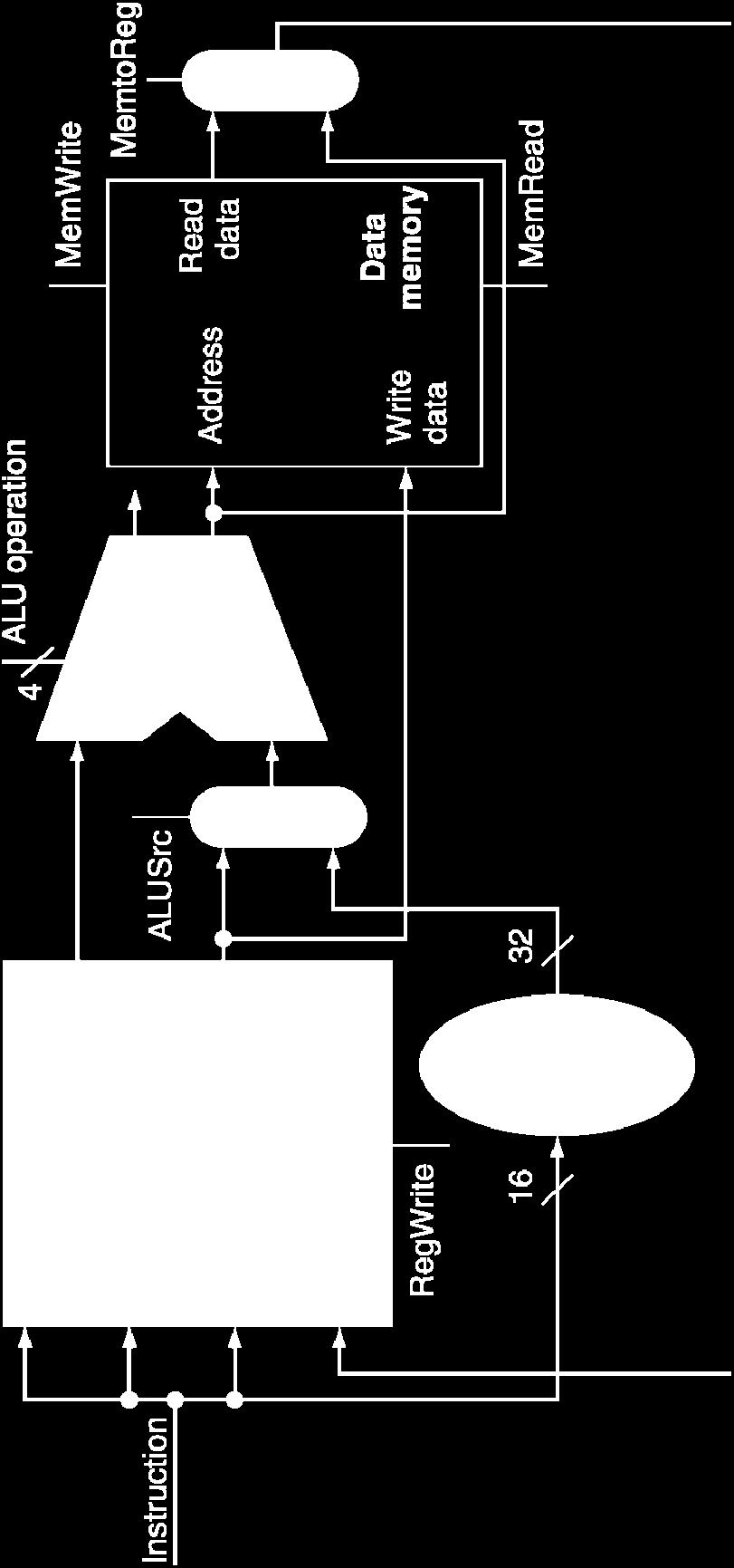
24 R-Type/Load/Store Datapath Chapter 4 The Processor 24
25 Recall Branch Operations beq rs, rt, imm op rs rt immediate 6 bits 5 bits 5 bits 16 bits 0 mem[pc] Fetch inst. from memory COND <- R[rs] == R[rt] Calculate branch condition if (COND == 0) Calculate next inst. address PC <- PC ( SignExt(imm16) x 4 ) else PC <- PC + 4 Chapter 4 The Processor 25
26 Branch Instructions Read register operands Compare operands Use ALU, subtract and check Zero output Calculate target address Sign-extend displacement Shift left 2 places (word displacement) Add to PC + 4 Already calculated by instruction fetch Chapter 4 The Processor 26


27 Step 3c: Branch Instructions Just re-routes wires Sign-bit wire replicated Chapter 4 The Processor 27
28 Composing the Elements First-cut data path does an instruction in one clock cycle Each datapath element can only do one function at a time Hence, we need separate instruction and data memories Use multiplexers where alternate data sources are used for different instructions Chapter 4 The Processor 28
29 A Single Cycle Full Datapath PCSrc 4 Add RegWrite Shift left 2 Add ALU result 1 M u x 0 PC Read address Instruction [31 0] Instruction memory Instruction [25 21] Instruction [20 16] 1 M u Instruction [15 11] x 0 RegDst Instruction [15 0] Read register 1 Read register 2 Write register Write data Read data 1 Read data 2 Registers 16 Sign 32 extend ALUSrc 1 M u x 0 ALU control ALU Zero ALU result MemWrite Address Write data Data memory MemRead Read data MemtoReg 1 M u x 0 Instruction [5 0] ALUOp Chapter 4 The Processor 29
30 Clocking Methodology Define when signals are read and written Assume edge-triggered (synchronous design): Values in storage (state) elements updated only on a clock edge => clock edge should arrive only after input signals stable Any combinational circuit must have inputs from and outputs to storage elements Clock cycle: time for signals to propagate from one storage element, through combinational circuit, to reach the second storage element A register can be read, its value propagated through some combinational circuit, new value is written back to the same register, all in same cycle => no feedback within a single cycle Chapter 4 The Processor 30
31 Register-Register Timing Clk PC Rs, Rt, Rd, Op, Func ALUctr Old Value Clk-to-Q New Value Old Value Old Value Instruction Memory Access Time New Value Delay through Control Logic New Value RegWr Old Value New Value busa, B busw Old Value Old Value Register File Access Time New Value ALU Delay New Value Clk PC Ideal Instruction Memory 32 RegWr busw 32 Clk Rd Rs Rt Rw Ra Rb bit Registers busa 32 busb 32 ALUctr ALU Register Write Occurs Here 32 Result
32 The Critical Path Register file and ideal memory: During read, behave as combinational logic: Address valid => Output valid after access time Instruction Address Next Address Clk Ideal Instruction Memory PC 32 Rd 5 Clk Instruction Rs 5 Rt 5 Rw Ra Rb bit Registers Imm 16 A 32 B 32 Critical Path (Load Operation) = PC s Clk-to-Q + Instruction memory s Access Time + Register file s Access Time + ALU to Perform a 32-bit Add + Data Memory Access Time + Setup Time for Register File Write + Clock Skew ALU 32 Data Address Data In Clk Ideal Data Memory
33 Clk PC Worst Case Timing (Load) Rs, Rt, Rd, Op, Func ALUctr Clk-to-Q New Value Old Value Instruction Memoey Access Time New Value Delay through Control Logic New Value RegWr Old Value New Value busa busb Old Value Old Value ExtOp Old Value New Value ALUSrc Old Value New Value MemtoReg Old Value New Value Old Value Delay through Extender & Mux Old Value Register Write Occurs Register File Access Time New Value New Value ALU Delay Address Old Value New Value Data Memory Access Time busw Old Value New
34 Step 4: Control Points and Signals Inst. Memory Addr Instruction<31:0> <21:25> OpFunct Rt <21:25> <16:20> Rs Rd <11:15> <0:15> Imm16 To select the operations to perform To control the flow of data Control PCsrc RegDst ALUSrc MemWr RegWr MemRd ALUct r MemtoReg Equal Datapath Chapter 4 The Processor 34

35 7 Control Signals Chapter 4 The Processor 35
36 ALU Control ALU used for Load/Store: F = add Branch: F = subtract R-type: F depends on funct field ALU control Function 0000 AND 0001 OR 0010 add 0110 subtract 0111 set-on-less-than 1100 NOR 4.4 A Simple Implementation Scheme Chapter 4 The Processor 36
37 ALU Control Assume 2-bit ALUOp derived from opcode Combinational logic derives ALU control opcode ALUOp Operation funct ALU function ALU control lw 00 load word XXXXXX add 0010 sw 00 store word XXXXXX add 0010 beq 01 branch equal XXXXXX subtract 0110 R-type 10 add add 0010 subtract subtract 0110 AND AND 0000 OR OR 0001 set-on-less-than set-on-less-than 0111 Chapter 4 The Processor 37
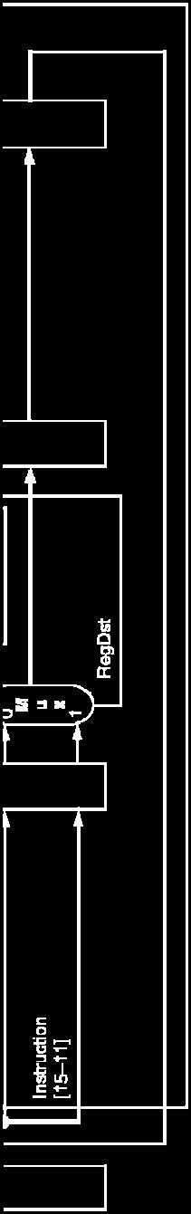
38 The Main Control Unit Control signals derived from instruction R-type Load/ Store Branch 0 rs rt rd shamt funct 31:26 25:21 20:16 15:11 10:6 5:0 35 or 43 rs rt address 31:26 25:21 20:16 15:0 4 rs rt address 31:26 25:21 20:16 15:0 opcode always read read, except for load write for R-type and load sign-extend and add Chapter 4 The Processor 38
39 Designing Main Control Some observations: opcode (Op[5-0]) is always in bits two registers to be read are always in rs (bits 25-21) and rt (bits 20-16) (for R-type, beq, sw) base register for lw and sw is always in rs (25-21) 16-bit offset for beq, lw, sw is always in 15-0 destination register is in one of two positions: lw: in bits (rt) R-type: in bits (rd) => need a multiplex to select the address for written register Chapter 4 The Processor 39
40 Datapath with Mux and Control PCSrc 4 Add RegWrite Shift left 2 Add ALU result 1 M u x 0 PC Read address Instruction [31 0] Instruction memory Instruction [25 21] Instruction [20 16] 1 M u Instruction [15 11] x 0 RegDst Instruction [15 0] Read register 1 Read register 2 Write register Write data Read data 1 Read data 2 Registers 16 Sign 32 extend ALUSrc 1 M u x 0 ALU control ALU Zero ALU result MemWrite Address Write data Data memory MemRead Read data MemtoReg 1 M u x 0 Control point Instruction [5 0] ALUOp Chapter 4 The Processor 40

41 Datapath With Control Chapter 4 The Processor 41

42 R-Type Instruction Chapter 4 The Processor 42
43 Load Instruction Chapter 4 The Processor 43


44 Branch-on-Equal Instruction Chapter 4 The Processor 44
45 Implementing Jumps Jump 2 address 31:26 25:0 Jump looks somewhat like a branch, but always computes the target PC (i.e. not conditional) Jump uses word address Update PC with concatenation of top 4 bits of old PC, 26-bit jump address, and 00 2 Need an extra control signal decoded from opcode Chapter 4 The Processor 45


46 Datapath With Jumps Added Chapter 4 The Processor 46
47 Concluding Remarks Not feasible to vary clock period for different instructions Longest delay determines clock period Critical path: load instruction Instruction memory register file ALU data memory register file Making the common case fast cannot improve the worst-case delay Single cycle implementation violates the design principle We will improve performance by pipelining Chapter 4 The Processor 47
48 Pipelining Implementation Critical path reduction storage element storage element Acyclic Combinational Logic ==> Acyclic Combinational Logic (A) storage element storage element Acyclic Combinational Logic (B) storage element


49 Pipelining Analogy Pipelined laundry: overlapping execution Parallelism improves performance Four loads: Speedup = 8/3.5 = 2.3 Non-stop: Speedup = 2n/0.5n = number of stages 4.5 An Overview of Pipelining Chapter 4 The Processor 49
50 Steps for Designing a Pipelined Processor Examine the datapath and control diagram Starting with single cycle datapath Partition datapath into stages: IF (instruction fetch), ID (instruction decode and register file read), EX (execution or address calculation), MEM (data memory access), WB (write back) Associate resources with stages Ensure that flows do not conflict, or figure out how to resolve Assert control in appropriate stage Chapter 4 The Processor 50
51 Partition Single-Cycle Datapath Add registers between smallest steps Ins. fetch RF access ALU operation memory access Write back PCSrc 4 Add Shift left 2 Add ALU result M u x PC Read address Instruction Instruction memory Read register 1 Read register 2 Write register Write data Registers Read data 1 Read data 2 RegWrite 16 Sign 32 extend ALUSrc M u x 4 3 ALU operation Zero ALU ALU result Address Write data MemRead MemWrite Read data Data memory MemtoReg M u x
52 5-Stage MIPS Pipeline Five steps, one stage per step 1. IF: Instruction fetch from memory 2. ID: Instruction decode & register read 3. EX: Execute operation or calculate address 4. MEM: Access memory operand 5. WB: Write result back to register Chapter 4 The Processor 52
53 Pipeline Performance Assume time for stages is 100ps for register read or write 200ps for other stages Compare pipelined datapath with single-cycle datapath Instr Instr fetch Register read ALU op Memory access Register write Total time lw 200ps 100 ps 200ps 200ps 100 ps 800ps sw 200ps 100 ps 200ps 200ps 700ps R-format 200ps 100 ps 200ps 100 ps 600ps beq 200ps 100 ps 200ps 500ps Chapter 4 The Processor 53

 Chapter 4 The")
54 Pipeline Performance Single-cycle (T c = 800ps) Pipelined (T c = 200ps) Chapter 4 The Processor 54
55 Pipeline Speedup If all stages are balanced i.e., all take the same time Time between instructions pipelined = Time between instructions nonpipelined Number of stages If not balanced, speedup is less Speedup due to increased throughput Latency (time for each instruction) does not decrease Chapter 4 The Processor 55
56 Pipelining Lessons Doesn t help latency of single task, but throughput of entire Pipeline rate limited by slowest stage Multiple tasks working at same time using different resources Potential speedup = Number pipe stages Unbalanced stage length; time to fill & drain the pipeline reduce speedup Stall for dependences or pipeline hazards 56
57 MIPS ISA Designed for Pipelining All instructions are 32-bits Easier to fetch and decode in one cycle c.f. x86: 1- to 17-byte instructions Few and regular instruction formats Can decode and read registers in one step Load/store addressing Can calculate address in 3 rd stage, access memory in 4 th stage Alignment of memory operands Memory access takes only one cycle Chapter 4 The Processor 57
58 Pipelined Datapath Use registers between stages to carry data and control 0 M u x 1 Pipeline registers (latches) IF/ID ID/EX EX/MEM MEM/WB Add 4 Shift left 2 Add Add result PC Address Instruction memory Instruction Read register 1 Read data 1 Read register 2 Registers Read data 2 Write register Write data 0 M u x 1 Zero ALU ALU result Address Write data Data memory Read data 1 M u x 0 16 Sign extend 32 Lecture06 - pipelining (cwliu@twins.ee.nctu.edu.tw) 58
59 Consider Load Instruction Cycle 1 Cycle 2 Cycle 3 Cycle 4 Cycle 5 Load Ifetch Reg/Dec Exec Mem Wr IF: Instruction Fetch Fetch the instruction from the Instruction Memory ID: Instruction Decode Registers fetch and instruction decode EX: Calculate the memory address MEM: Read the data from the Data Memory WB: Write the data back to the register file 59
60 Pipelining lw Instructions Clock Cycle 1 Cycle 2 Cycle 3 Cycle 4 Cycle 5 Cycle 6 Cycle 7 1st lw Ifetch Reg/Dec Exec Mem Wr 2nd lw Ifetch Reg/Dec Exec Mem Wr 3rd lw Ifetch Reg/Dec Exec Mem Wr 5 functional units in the pipeline datapath are: Instruction Memory for the Ifetch stage Register File s Read ports (busa and busb) for the Reg/Dec stage ALU for the Exec stage Data Memory for the MEM stage Register File s Write port (busw) for the WB stage 60
61 The Four Stages of R-type Instruction Cycle 1 Cycle 2 Cycle 3 Cycle 4 R-type Ifetch Reg/Dec Exec Wr IF: fetch the instruction from the Instruction Memory ID: registers fetch and instruction decode EX: ALU operates on the two register operands WB: write ALU output back to the register file Lecture06 - pipelining (cwliu@twins.ee.nctu.edu.tw) 61
62 Hazard Problem Clock Cycle 1 Cycle 2 Cycle 3 Cycle 4 Cycle 5 Cycle 6 Cycle 7 Cycle 8 Cycle 9 R-type Ifetch Reg/Dec Exec Wr Ops! We have a problem! R-type Ifetch Reg/Dec Exec Wr Load Ifetch Reg/Dec Exec Mem Wr R-type Ifetch Reg/Dec Exec Wr R-type Ifetch Reg/Dec Exec Wr We have a structural hazard: Two instructions try to write to the RF at the same time, but only one write port! Lecture06 - pipelining (cwliu@twins.ee.nctu.edu.tw) 62
63 Pipeline Hazards Situations that prevent starting the next instruction in the next cycle Structure hazard A required resource is busy Data hazard Need to wait for previous instruction to complete its data read/write Control hazard Deciding on control action depends on previous instruction Several ways to solve: forwarding, adding pipeline bubble, making instructions same length Chapter 4 The Processor 63
64 Structure Hazards Conflict for use of a resource In MIPS pipeline with a single memory Load/store requires data access Instruction fetch would have to stall for that cycle Would cause a pipeline bubble Hence, pipelined datapaths require separate instruction/data memories Or separate instruction/data caches Chapter 4 The Processor 64
65 Structural Hazard Solution: Seperate I/D Memory Time I n s t r. O r d e r Load Instr 1 Instr 2 Instr 3 Instr 4 ALU Mem Reg Mem ALU Reg Mem Reg Mem Reg Mem Reg Mem Reg ALU Mem Reg ALU Mem Reg ALU Mem Reg Mem Reg 1. I/D separate memory: data memory and instruction memory 2. First half cycle for write and the second half cycle for read Lecture06 - pipelining (cwliu@twins.ee.nctu.edu.tw) 65
66 Structural Hazard Solution: Delay R-type s Write Delay R-type s register write by one cycle: R-type also use Reg File s write port at Stage 5 MEM is a NOP stage: nothing is being done. R-type Ifetch Reg/Dec Exec Mem Wr R-type also has 5 stages Cycle 1 Cycle 2 Cycle 3 Cycle 4 Cycle 5 Cycle 6 Cycle 7 Cycle 8 Cycle 9 Clock R-type Ifetch Reg/Dec Exec Mem Wr R-type Ifetch Reg/Dec Exec Mem Wr Load Ifetch Reg/Dec Exec Mem Wr R-type Ifetch Reg/Dec Exec Mem Wr R-type Ifetch Reg/Dec Exec Mem Wr Lecture06 - pipelining (cwliu@twins.ee.nctu.edu.tw) 66
67 The Four Stages of sw Cycle 1 Cycle 2 Cycle 3 Cycle 4 Store Ifetch Reg/Dec Exec Mem Wr IF: fetch the instruction from the Instruction Memory ID: registers fetch and instruction decode EX: calculate the memory address MEM: write the data into the Data Memory Add an extra stage: WB: NOP Lecture06 - pipelining (cwliu@twins.ee.nctu.edu.tw) 67
68 The Three Stages of beq Cycle 1 Cycle 2 Cycle 3 Cycle 4 Beq Ifetch Reg/Dec Exec Mem Wr IF: fetch the instruction from the Instruction Memory ID: registers fetch and instruction decode EX: compares the two register operand select correct branch target address latch into PC Add two extra stages: MEM: NOP WB: NOP Lecture06 - pipelining (cwliu@twins.ee.nctu.edu.tw) 68


69 Data Hazards An instruction depends on completion of data access by a previous instruction add $s0, $t0, $t1 sub $t2, $s0, $t3 Chapter 4 The Processor 69
70 Types of Data Hazards Three types: (inst. i1 followed by inst. i2) RAW (read after write): True data dependency i2 tries to read operand before i1 writes it WAR (write after read): Name dependency i2 tries to write operand before i1 reads it Gets wrong operand, e.g., autoincrement addr. Can t happen in MIPS 5-stage pipeline because: All instructions take 5 stages, and reads are always in stage 2, and writes are always in stage 5 WAW (write after write): i2 tries to write operand before i1 writes it Leaves wrong result ( i1 s not i2 s); occur only in pipelines that write in more than one stage Can t happen in MIPS 5-stage pipeline because: RAR? Name dependency All instructions take 5 stages, and writes are always in stage 5 No dependency Chapter 4 The Processor 70
71 Handling Data Hazards Use simple, fixed designs Eliminate WAR by always fetching operands early (ID) in pipeline Eliminate WAW by doing all write backs in order (last stage, static) These features have a lot to do with ISA design Internal forwarding in register file: Write in first half of clock and read in second half Read delivers what is written, resolve hazard between sub and add Detect and resolve remaining ones Compiler inserts NOP, or reorders the code sequence Forward Stall Chapter 4 The Processor 71


72 Forwarding (aka Bypassing) Use result when it is computed Don t wait for it to be stored in a register Requires extra connections in the datapath Hardware complexity Chapter 4 The Processor 72
73 Example Consider the following code sequence sub $2, $1, $3 and $12, $2, $5 or $13, $6, $2 add $14, $2, $2 sw $15, 100($2) Chapter 4 The Processor 73
74 Data Hazards Solution: Inserting NOPs by Software Time (in clock cycles) Value of register $2: Program execution order (in instructions) sub $2, $1,$3 CC 1 CC 2 CC 3 CC 4 CC 5 CC 6 IM Insert two nops Reg CC 7 CC 8 CC / DM Reg and $12, $2, $5 IM Reg DM Reg or $13, $6, $2 IM Reg DM Reg add $14, $2, $2 IM Reg DM Reg sw $15, 100($2) IM Reg DM Reg Lecture06 - pipelining (cwliu@twins.ee.nctu.edu.tw) 74
75 Data Hazards Solution: Internal Forwarding Logic Use temporary results, e.g., those in pipeline registers, don t wait for them to be written Time (in clock cycles) CC 1 CC 2 CC 3 CC 4 CC 5 CC 6 CC 7 CC 8 CC 9 Value of register $2 : / Value of EX/MEM : X X X 20 X X X X X Value of MEM/WB : X X X X 20 X X X X Program execution order (in instructions) sub $2, $1, $3 IM Reg DM Reg and $12, $2, $5 IM Reg DM Reg or $13, $6, $2 IM Reg DM Reg add $14, $2, $2 IM Reg DM Reg sw $15, 100($2) IM Reg DM Reg
76 HW Change for Forwarding Additional hardware is required. NextPC Registers ID/EX mux mux ALU EX/MEM Data Memory MEM/WR Immediate mux Chapter 4 The Processor 76


77 Load-Use Data Hazard Can t always avoid stalls by forwarding If value not computed when needed Can t forward backward in time! Software Check or Hardware Handling How to insert a bubble??? Chapter 4 The Processor 77
78 Rescheduling Code to Avoid Stalls Compiler reorders the code sequence to avoid use of load result in the next instruction C code for A = B + E; C = B + F; stall stall lw $t1, 0($t0) lw $t2, 4($t0) add $t3, $t1, $t2 sw $t3, 12($t0) lw $t4, 8($t0) add $t5, $t1, $t4 sw $t5, 16($t0) 13 cycles lw $t1, 0($t0) lw $t2, 4($t0) lw $t4, 8($t0) add $t3, $t1, $t2 sw $t3, 12($t0) add $t5, $t1, $t4 sw $t5, 16($t0) 11 cycles Chapter 4 The Processor 78
79 Control Hazard on Branches 10: beq r1,r3,36 Ifetch Reg ALU DMem Reg 14: and r2,r3,r5 Ifetch Reg ALU DMem Reg 18: or r6,r1,r7 Ifetch Reg ALU DMem Reg 22: add r8,r1,r9 Ifetch Reg ALU DMem Reg 36: xor r10,r1,r11 Ifetch Reg ALU DMem Reg What do you do with the 3 instructions in between? The simplest solution is to stall the pipeline as soon as a branch instruction is detected Chapter 4 The Processor 79
80 Branch Stall Impact If CPI = 1, 30% branch, Stall 3 cycles => new CPI = 1.9! Two-part solution: Determine branch taken or not sooner, AND Compute taken branch address earlier MIPS branch tests if register = 0 or 0 MIPS Solution: Move Zero test to ID/RF stage Adder to calculate new PC in ID/RF stage 1 clock cycle penalty for branch versus 3 Chapter 4 The Processor 80


81 Stall on Branch Wait until branch outcome determined before fetching next instruction How to add a stall cycle? Chapter 4 The Processor 81
82 Four Alternatives for Control Hazard #1: Stall until branch direction is clear #2: Predict Branch Not Taken Execute successor instructions in sequence Squash instructions in pipeline if branch actually taken Advantage of late pipeline state update PC+4 already calculated, so use it to get next instruction #3: Predict Branch Taken But haven t calculated branch target address in MIPS, it still incurs 1 cycle branch penalty Advantage of branch target is known before outcome Chapter 4 The Processor 82
83 Four Alternatives for Control Hazard #4: Delayed Branch make the stall cycle useful Define branch to take place AFTER a following instruction branch instruction sequential successor 1 sequential successor 2... sequential successor n branch target if taken Branch delay of length n These insts. are executed!! 0-cycle latency, if all the stall cycles are useful Chapter 4 The Processor 83
84 Handling Branch Hazard Moving branch execution earlier in the pipeline Move up branch address calculation to ID Check branch equality at ID (using XOR for zero test) by comparing the two registers read during ID Branch decision made at ID => one instruction to flush Add a control signal, IF.Flush, to zero instruction field of IF/ID => making the instruction an NOP (i.e. bubble instruction) (Static) Predict branch always not taken Need to add hardware for flushing inst. if wrong Compiler rescheduling and delay branch (discussed later) Dynamic branch prediction (discussed later) Chapter 4 The Processor 84


85 MIPS with Predict Not Taken Prediction correct Prediction incorrect Chapter 4 The Processor 85
86 More-Realistic Branch Prediction Static n-bit branch prediction Based on typical branch behavior Example: loop and if-statement branches Predict backward branches taken Predict forward branches not taken Dynamic branch prediction Hardware measures actual branch behavior e.g., record recent history of each branch Assume future behavior will continue the trend When wrong, stall while re-fetching, and update history Chapter 4 The Processor 86
87 Pipeline Operation Cycle-by-cycle flow of instructions through the pipelined datapath Single-clock-cycle pipeline diagram Shows pipeline usage in a single cycle Highlight resources used c.f. multi-clock-cycle diagram Graph of operation over time Chapter 4 The Processor 87
88 Recall: Steps for Designing a Pipelined Processor Examine the datapath and control diagram Starting with single cycle datapath Partition datapath into stages: IF (instruction fetch), ID (instruction decode and register file read), EX (execution or address calculation), MEM (data memory access), WB (write back) Associate resources with stages 4.6 Pipelined Datapath and Control Ensure that flows do not conflict, or figure out how to resolve Assert control in appropriate stage Chapter 4 The Processor 88


89 MIPS Single-Cycle Datapath Two right-to-left flows MEM Right-to-left flows lead to hazards WB Chapter 4 The Processor 89
90 Pipeline Registers Use registers between stages to carry data and control 0 M u x 1 Pipeline registers (latches) IF/ID ID/EX EX/MEM MEM/WB Add 4 Shift left 2 Add Add result PC Address Instruction memory Instruction Read register 1 Read data 1 Read register 2 Registers Read data 2 Write register Write data 0 M u x 1 Zero ALU ALU result Address Write data Data memory Read data 1 M u x 0 16 Sign extend 32 Chapter 4 The Processor 90
91 MIPS ISA Micro-Operations One way to show what happens in pipelined execution Step name Instruction fetch Instruction decode/register fetch Action for R-type instructions Action for memory-reference Action for instructions branches IR = Memory[PC] PC = PC + 4 A = Reg [IR[25-21]] B = Reg [IR[20-16]] ALUOut = PC + (sign-extend (IR[15-0]) << 2) Action for jumps Execution, address ALUOut = A op B ALUOut = A + sign-extend if (A ==B) then PC = PC [31-28] II computation, branch/ (IR[15-0]) PC = ALUOut (IR[25-0]<<2) jump completion Memory access or R-type Reg [IR[15-11]] = Load: MDR = Memory[ALUOut] completion ALUOut or Store: Memory [ALUOut] = B Memory read completion Load: Reg[IR[20-16]] = MDR Chapter 4 The Processor 91
92 MIPS ISA Micro-Operations Step name Instruction fetch Action for R-type instructions IR = Memory[PC] PC = PC + 4 Action for memory-reference instructions Action for branches Action for jumps Instruction decode & register fetch Execution/ address ALUOut = A op B A = Reg [IR[25-21]]; B = Reg [IR[20-16]] if (A ==B) then, ALUOut = PC + (sign-extend (IR[15-0]) << 2) ALUOut = A + sign-extend PC = PC [31-28] II computation (IR[15-0]) (IR[25-0]<<2) Memory access or R-type completion Memory read completion/ Reg [IR[15-11]] = R-type completion ALUOut Load: MDR = Memory[ALUOut] or Store: Memory [ALUOut] = B Load: Reg[IR[20-16]] = MDR Chapter 4 The Processor 92
93 Pipeline Operation Cycle-by-cycle flow of instructions through the pipelined datapath Shows pipeline usage in a single cycle (stage) Highlight resources used We ll look at single-clock-cycle diagrams for load instruction Chapter 4 The Processor 93
94 IF Stage of lw Ex: lw rt,rs,imm16 lw Instruction fetch 0 M u x 1 IR, PC+4 IF/ID ID/EX EX/MEM MEM/WB Add 4 Shift left 2 Add Add result PC Address Instruction memory Instruction Read register 1 Read data 1 Read register 2 Registers Read data 2 Write register Write data 0 M u x 1 Zero ALU ALU result Address Data memory Write data Read data 1 M u x 0 16 Sign extend 32 Chapter 4 The Processor 94
95 ID Stage of lw Ex: lw rt,rs,imm16 A = Reg[IR[25-21]]; 0 M u x 1 lw Instruction decode IF/ID ID/EX EX/MEM MEM/WB Add 4 Shift left 2 Add Add result PC Address Instruction memory Instruction Read register 1 Read Read data 1 register 2 Registers Read data 2 Write register Write data 0 M u x 1 Zero ALU ALU result Address Data memory Write data Read data 1 M u x 0 16 Sign extend 32 Chapter 4 The Processor 95
96 EX Stage of lw Ex: lw rt,rs,imm16 ALUout = A + sign-ext(ir[15-0]) 0 M u x 1 lw Execution IF/ID ID/EX EX/MEM MEM/WB Add 4 Shift left 2 Add Add result PC Address Instruction memory Instruction Read register 1 Read data 1 Read register 2 Registers Read data 2 Write register Write data 0 M u x 1 Zero ALU ALU result Address Data memory Write data Read data 1 M u x 0 16 Sign extend 32 Chapter 4 The Processor 96
97 MEM State of lw Ex: lw rt,rs,imm16 MDR = mem[aluout] 0 M u x 1 lw Memory IF/ID ID/EX EX/MEM MEM/WB Add 4 Shift left 2 Add Add result PC Address Instruction memory Instruction Read register 1 Read Read data 1 register 2 Registers Read data 2 Write register Write data 0 M u x 1 Zero ALU ALU result Address Data memory Write data Read data 1 M u x 0 16 Sign extend 32 Chapter 4 The Processor 97
98 WB Stage of lw Ex: lw rt,rs,imm16 Reg[IR[20-16]] = MDR 0 M u x 1 Who will supply this address? lw Write back IF/ID ID/EX EX/MEM MEM/WB Add 4 Shift left 2 Add Add result PC Address Instruction memory Instruction Read register 1 Read data 1 Read register 2 Registers Read data 2 Write register Write data 0 M u x 1 Zero ALU ALU result Address Data memory Write data Read data 1 M u x 0 16 Sign extend 32
99 Pipelined Datapath 0 M u x 1 IF/ID ID/EX EX/MEM MEM/WB Add 4 Shift left 2 Add result Add PC Address Instruction memory Instruction Read register 1 Read data 1 Read register 2 Registers Read data 2 Write register Write data 0 M u x 1 Zero ALU ALU result Address Write data Data memory Read data 1 M u x 0 16 Sign extend 32 Chapter 4 The Processor 99


100 Pipeline Diagram Multi-clock-cycle pipeline diagram Chapter 4 The Processor 100


101 Pipeline diagram Single-clock-cycle diagram in a given cycle cc5 Chapter 4 The Processor 101
 single-cycle datapath Use the same")

102 Pipelined Control (1) Start with the (simplified) single-cycle datapath Use the same ALU control logic, branch logic, destination-registernumber MUX, and control lines Chapter 4 The Processor 102
103 Pipelined Control (2) To specify control for the pipeline, we need to set control values during each pipeline stage. The simplest implementation way is data stationary pipelined control: to extend the pipeline registers to include control information Chapter 4 The Processor 103


104 Data Stationary Pipelined Control Control signals derived from instruction Main control generates control signals during ID Pass control signals along just like the data Chapter 4 The Processor 104
105 Data Stationary Control Signals for EX (ExtOp, ALUSrc,...) are used 1 cycle later Signals for MEM (MemWr, Branch) are used 2 cycles later Signals for WB (MemtoReg, MemWr) are used 3 cycles later ID EX MEM WB ExtOp ExtOp ALUSrc ALUSrc IF/ID Register Main Control ALUOp RegDst MemWr Branch MemtoReg ID/Ex Register ALUOp RegDst MemWr Branch MemtoReg Ex/MEM Register MemW Branch MemtoReg MEM/WB Register MemtoReg RegWr RegWr RegWr RegWr Lecture06 - pipelining (cwliu@twins.ee.nctu.edu.tw) 105


106 Pipelined Control Chapter 4 The Processor 106
107 Hazard Detection We can resolve hazards with forwarding, but how do we detect when to forward? RAW (WAR, WAW) dependence check i.e. to compare register number between instructions Pass register numbers along pipeline ID/EX.RegisterRs = register number for Rs sitting in ID/EX pipeline register e.g. ALU operand register numbers in EX stage are given by ID/EX.RegisterRs, ID/EX.RegisterRt Data hazards when 1a. EX/MEM.RegisterRd = ID/EX.RegisterRs 1b. EX/MEM.RegisterRd = ID/EX.RegisterRt 2a. MEM/WB.RegisterRd = ID/EX.RegisterRs 2b. MEM/WB.RegisterRd = ID/EX.RegisterRt 4.7 Data Hazards: Forwarding vs. Stalling Chapter 4 The Processor 107
108 Detecting the Need to Forward Not always do fordward if true data hazard But only if forwarding instruction will write to a register! EX/MEM.RegWrite, MEM/WB.RegWrite And only if Rd for that instruction is not $zero EX/MEM.RegisterRd 0, MEM/WB.RegisterRd 0 Chapter 4 The Processor 108


109 Forwarding Paths Chapter 4 The Processor 109
110 Forwarding Conditions EX hazard if (EX/MEM.RegWrite and (EX/MEM.RegisterRd 0) and (EX/MEM.RegisterRd = ID/EX.RegisterRs)) ForwardA = 10 if (EX/MEM.RegWrite and (EX/MEM.RegisterRd 0) and (EX/MEM.RegisterRd = ID/EX.RegisterRt)) ForwardB = 10 MEM hazard if (MEM/WB.RegWrite and (MEM/WB.RegisterRd 0) and (MEM/WB.RegisterRd = ID/EX.RegisterRs)) ForwardA = 01 if (MEM/WB.RegWrite and (MEM/WB.RegisterRd 0) and (MEM/WB.RegisterRd = ID/EX.RegisterRt)) ForwardB = 01 Chapter 4 The Processor 110
111 Double Data Hazard Consider the sequence: add $1,$1,$2 add $1,$1,$3 add $1,$1,$4 Both hazards occur Want to use the most recent Revise MEM hazard condition Only forward if EX hazard condition isn t true Chapter 4 The Processor 111
112 Revised Forwarding Condition MEM hazard if (MEM/WB.RegWrite and (MEM/WB.RegisterRd 0) and not (EX/MEM.RegWrite and (EX/MEM.RegisterRd 0) and (EX/MEM.RegisterRd = ID/EX.RegisterRs)) and (MEM/WB.RegisterRd = ID/EX.RegisterRs)) ForwardA = 01 if (MEM/WB.RegWrite and (MEM/WB.RegisterRd 0) and not (EX/MEM.RegWrite and (EX/MEM.RegisterRd 0) and (EX/MEM.RegisterRd = ID/EX.RegisterRt)) and (MEM/WB.RegisterRd = ID/EX.RegisterRt)) ForwardB = 01 Chapter 4 The Processor 112


113 Datapath with Forwarding Chapter 4 The Processor 113

114 Load-Use Data Hazard Need to stall for one cycle Chapter 4 The Processor 114
115 Load-Use Hazard Detection Check when using instruction is decoded in ID stage ALU operand register numbers in ID stage are given by IF/ID.RegisterRs, IF/ID.RegisterRt Load-use hazard when ID/EX.MemRead and ((ID/EX.RegisterRt = IF/ID.RegisterRs) or (ID/EX.RegisterRt = IF/ID.RegisterRt)) If detected, stall and insert bubble Chapter 4 The Processor 115
116 How to Stall the Pipeline Force control values in ID/EX register to 0 EX, MEM and WB do nop (no-operation) Prevent update of PC and IF/ID register Using instruction is decoded again Following instruction is fetched again 1-cycle stall allows MEM to read data for lw Can subsequently forward to EX stage Chapter 4 The Processor 116


117 Stall/Bubble in the Pipeline Stall inserted here Chapter 4 The Processor 117


118 Stall/Bubble in the Pipeline Or, more accurately Chapter 4 The Processor 118


119 Datapath with Hazard Detection Chapter 4 The Processor 119
120 Stalls and Performance The BIG Picture Stalls reduce performance But are required to get correct results Compiler can arrange code to avoid hazards and stalls Requires knowledge of the pipeline structure Chapter 4 The Processor 120
121 Branch Hazards If branch outcome determined in MEM 4.8 Control Hazards Original Datapath Flush these instructions (Set control values to 0) PC Chapter 4 The Processor 121


122 Reducing Branch Delay Move hardware to determine outcome to ID stage Target address adder Register comparator additional hardware Chapter 4 The Processor 122
123 Data Hazards for Branch -- I If a comparison register is a destination of 2 nd or 3 rd preceding ALU instruction add $1, $2, $3 IF ID EX MEM WB add $4, $5, $6 IF ID EX MEM WB beq $1, $4, target IF ID EX MEM WB IF ID EX MEM WB Can resolve using forwarding, but need 1 stall cycle Chapter 4 The Processor 123
124 Data Hazards for Branch -- I 1 stall cycle + forwarding for ALU results lw $1, addr IF ID EX MEM WB add $4, $5, $6 IF ID EX MEM WB beq stalled IF ID beq $1, $4, target ID EX MEM WB Chapter 4 The Processor 124
125 Data Hazards for Branch -- II If a comparison register is a destination of immediately preceding load instruction Can resolve using forwarding, but need 2 stall cycles lw $1, addr IF ID EX MEM WB beq stalled IF ID beq stalled ID beq $1, $0, target ID EX MEM WB Chapter 4 The Processor 125
126 Delayed Branch Predict-not-taken + branch decision at ID => the following instruction is always executed => branches take effect 1 cycle later I n s t r. O r d e r add beq misc lw Time (clock cycles) ALU Mem Reg Mem Reg ALU Mem Reg Mem Reg Mem ALU Reg Mem Reg Mem ALU Reg Mem Reg 0 clock cycle penalty per branch instruction if can find instruction to put in slot Lecture06 - pipelining (cwliu@twins.ee.nctu.edu.tw) 126
127 Scheduling the Branch Delay Slot A is the best choice, fills delay slot & reduces instruction count (IC) In B, the sub instruction may need to be copied, increasing IC In B and C, must be okay to execute sub when branch fails Chapter 4 The Processor 127
128 Delay-Branch Scheduling Schemes Scheduling Strategy From before Requirements Branch must not depend on the rescheduled instructions Improve Performance When? Always From target From fall through Must be OK to execute rescheduled instructions if branch is not taken. May need to duplicate instructions Must be OK to execute instructions if branch is taken When branch is taken. May enlarge program if instructions are duplicated When branch is not taken. CA-Lec4 128
129 Dynamic Branch Prediction In deeper and superscalar pipelines, branch penalty is more significant Use dynamic branch prediction Branch prediction buffer (aka branch history table) Indexed by recent branch instruction addresses Stores outcome (taken/not taken) To execute a branch Check table, expect the same outcome Start fetching from fall-through or target If wrong, flush pipeline and flip prediction 1-bit predictor Chapter 4 The Processor 129
130 Shortcoming for 1-Bit Predictor Inner loop branches mispredicted twice! outer: inner: beq,, inner beq,, outer T NT Mispredict as taken on last iteration of inner loop Then mispredict as not taken on first iteration of inner loop next time around Chapter 4 The Processor 130


131 2-Bit Predictor Only change prediction on two successive mispredictions Chapter 4 The Processor 131
132 Calculating the Branch Target Address Even with predictor, still need to calculate the target address 1-cycle penalty for a taken branch in 5-stage MIPS processor Branch target buffer (discussed in CA course) Cache of target addresses Indexed by PC when instruction fetched If hit and instruction is branch predicted taken, can fetch target immediately 0-cycle penalty Chapter 4 The Processor 132

133 Exceptions and Interrupts Unexpected events requiring change in flow of control Different ISAs use the terms differently 4.9 Exceptions Exception: Arises within the CPU e.g., undefined opcode, overflow, syscall, Interrupt: From an external I/O controller Dealing with execeptions without sacrificing performance is hard Chapter 4 The Processor 133
134 Handling Exceptions in MIPS In MIPS, exceptions managed by a System Control Coprocessor (CP0) 1. Save PC of offending (or interrupted) instruction in Exception Program Counter (EPC) 2. Save indication of the problem in Cause register Must know the reason for the exception Cause is a status register We ll assume 1-bit 0 for undefined opcode, 1 for overflow 3. Save registers in memory (similar to procedure call) 4. Jump to exception handler at Chapter 4 The Processor 134
135 An Alternate Mechanism Vectored Interrupts Handler address determined by the cause Example: Undefined opcode: C Overflow: C : C Instructions either Deal with the interrupt, or Jump to real handler Chapter 4 The Processor 135
136 Handler Actions Read cause, and transfer to relevant handler Determine action required If restartable Take corrective action Must subtract 4 from EPC use EPC to return to program (also need to restore the saved registers from memory) Otherwise Terminate program Report error using EPC, cause, Chapter 4 The Processor 136
137 Exceptions in a Pipeline Another form of control hazard Consider overflow on add in EX stage add $1, $2, $1 Prevent $1 from being clobbered Complete previous instructions Flush add and subsequent instructions Set Cause and EPC register values Transfer control to handler Similar to mispredicted branch Use much of the same hardware Chapter 4 The Processor 137


138 Pipeline with Exceptions Zeros control signals for flushing Chapter 4 The Processor 138
139 Exception Summary Restartable exceptions Pipeline can flush the instruction Handler executes, then returns to the instruction Refetched and executed from scratch PC saved in EPC register Identifies causing instruction Actually PC + 4 is saved Handler must adjust Chapter 4 The Processor 139
140 Exception Example Exception on add in 40 sub $11, $2, $4 44 and $12, $2, $5 48 or $13, $2, $6 4C add $1, $2, $1 50 slt $15, $6, $7 54 lw $16, 50($7) Handler sw $25, 1000($0) sw $26, 1004($0) Chapter 4 The Processor 140


141 Exception Example 4C h + 4 = 50 h saved in EPC Clock 6 Chapter 4 The Processor 141


142 Exception Example The add and following instructions are flushed Clock 7 Chapter 4 The Processor 142
143 Multiple Exceptions Pipelining overlaps multiple instructions Could have multiple exceptions at once Simple approach: deal with exception from earliest instruction Flush subsequent instructions Precise exceptions In complex pipelines Multiple instructions issued per cycle Out-of-order completion Maintaining precise exceptions is difficult! (discussed in CA course) Chapter 4 The Processor 143
144 Imprecise Exceptions Just stop pipeline and save state Including exception cause(s) Let the handler work out Which instruction(s) had exceptions Which to complete or flush May require manual completion Simplifies hardware, but more complex handler software Not feasible for complex multiple-issue out-of-order pipelines Chapter 4 The Processor 144
145 Instruction-Level Parallelism (ILP) Pipelining: executing multiple instructions in parallel To increase ILP Deeper pipeline (increase clock rate) Less work per stage shorter clock cycle Multiple issue (using multiple ALUs) Replicate pipeline stages multiple pipelined datapaths Start multiple instructions per clock cycle CPI < 1, so use Instructions Per Cycle (IPC) E.g., 4GHz 4-way multiple-issue (upto 4 parallel instructions) 16 BIPS, peak CPI = 0.25, peak IPC = 4, ideally But dependencies reduce this in practice 4.10 Parallelism via Instructions Chapter 4 The Processor 145
146 Multiple Issue Processor Static multiple issue or VLIW processor Compiler solves hazards, groups instructions to be issued together, and packages them into issue slots Compiler detects and avoids hazards Dynamic multiple issue or Superscalar processor CPU examines instruction stream and chooses instructions to issue each cycle Compiler can help by reordering instructions CPU resolves hazards using advanced techniques at runtime Rescheduling and loop unrolling techniques for multiple issue processors Chapter 4 The Processor 146
147 MIPS with Static Dual Issue Two-issue packets One for ALU/branch instruction and the other for load/store instruction 64-bit aligned, 2-issue slot Pad an unused instruction with nop Peak IPC = 2 Address Instruction type Pipeline Stages n ALU/branch IF ID EX MEM WB n + 4 Load/store IF ID EX MEM WB n + 8 ALU/branch IF ID EX MEM WB n + 12 Load/store IF ID EX MEM WB n + 16 ALU/branch IF ID EX MEM WB n + 20 Load/store IF ID EX MEM WB Chapter 4 The Processor 147
148 Code Rescheduling Loop: lw $t0, 0($s1) addu $t0, $t0, $s2 sw $t0, 0($s1) addi $s1, $s1, -4 bne $s1, $zero, Loop After code rescheduling: Loop: lw $t0, 0($s1) addi $s1, $s1, -4 addu $t0, $t0, $s2 sw $t0, 4($s1) bne $s1, $zero, Loop Chapter 4 The Processor 148
149 Loop Unrolling Replicate loop body to expose more parallelism Reduces loop-control overhead Use different registers per replication Called register renaming Avoid loop-carried anti-dependencies Store followed by a load of the same register Aka name dependence Reuse of a register name Chapter 4 The Processor 149
 Assume the loop index is a multiple of four After four-times loop")
 Closer to 2, but at cost of registers and code size Chapter 4 The")
150 Multiple-Issue Code Scheduling 2-issue processor CPI: 4/5 = 0.8 (or IPC = 1.25) Assume the loop index is a multiple of four After four-times loop unrolling and code scheduling Blank is nop CPI: 8/14 = 0.57 (or IPC = 1.75) Closer to 2, but at cost of registers and code size Chapter 4 The Processor 150
151 Static Multiple Issue Processor Compiler must remove some/all hazards Reorder instructions into issue packets No dependencies with a packet Possibly some dependencies between packets Varies between ISAs; compiler must know! Insert nop(s), if necessary Software complexity Hardware complexity Chapter 4 The Processor 151


152 Two-Issue MIPS VLIW Processor Chapter 4 The Processor 152
153 Dynamic Multiple Issue Processor CPU decides whether to issue 0, 1, 2, each cycle (out-of-order execution and completion) Avoiding structural and data hazards Avoids the need for compiler scheduling Though it may still help Code semantics ensured by the CPU Old code still run May not re-compile the code for new version Hardware complexity Software complexity Chapter 4 The Processor 153


154 Superscalar Processor Preserves dependencies Hold pending operands Results also sent to any waiting reservation stations Reorders buffer for register writes Can supply operands for issued instructions Chapter 4 The Processor 154
155 Speculation Predict and continue to do with an instruction Start operation as soon as possible Check whether guess was right If so, complete the operation If not, roll-back and do the right thing Common to static and dynamic multiple issue Examples Speculate on branch outcome Roll back if path taken is different Speculate on load Roll back if location is updated Chapter 4 The Processor 155
156 Compiler/Hardware Speculation Compiler can reorder instructions e.g., move load before branch Can include fix-up instructions to recover from incorrect guess Hardware can look ahead for instructions to execute Buffer results until it determines they are actually needed Flush buffers on incorrect speculation Chapter 4 The Processor 156
157 Speculation and Exceptions What if exception occurs on a speculatively executed instruction? e.g., speculative load before null-pointer check Static speculation Can add ISA support for deferring exceptions Dynamic speculation Can buffer exceptions until instruction completion (which may not occur) Chapter 4 The Processor 157
158 Does Multiple Issue Work? The BIG Picture Yes, but not as much as we d like Programs have real dependencies that limit ILP Some dependencies are hard to eliminate e.g., pointer aliasing Some parallelism is hard to expose Limited window size during instruction issue Memory delays and limited bandwidth Hard to keep pipelines full Speculation can help if done well Chapter 4 The Processor 158
COMPUTER ORGANIZATION AND DESIGN
 COMPUTER ORGANIZATION AND DESIGN 5 Edition th The Hardware/Software Interface Chapter 4 The Processor 4.1 Introduction Introduction CPU performance factors Instruction count CPI and Cycle time Determined
COMPUTER ORGANIZATION AND DESIGN The Hardware/Software Interface. 5 th. Edition. Chapter 4. The Processor
 COMPUTER ORGANIZATION AND DESIGN The Hardware/Software Interface 5 th Edition Chapter 4 The Processor Introduction CPU performance factors Instruction count Determined by ISA and compiler CPI and Cycle
Chapter 4. The Processor
 Chapter 4 The Processor Introduction CPU performance factors Instruction count Determined by ISA and compiler CPI and Cycle time Determined by CPU hardware We will examine two MIPS implementations A simplified
Full Datapath. Chapter 4 The Processor 2
 Pipelining Full Datapath Chapter 4 The Processor 2 Datapath With Control Chapter 4 The Processor 3 Performance Issues Longest delay determines clock period Critical path: load instruction Instruction memory
Department of Computer and IT Engineering University of Kurdistan. Computer Architecture Pipelining. By: Dr. Alireza Abdollahpouri
 Department of Computer and IT Engineering University of Kurdistan Computer Architecture Pipelining By: Dr. Alireza Abdollahpouri Pipelined MIPS processor Any instruction set can be implemented in many
Chapter 4. The Processor
 Chapter 4 The Processor Recall. ISA? Instruction Fetch Instruction Decode Operand Fetch Execute Result Store Next Instruction Instruction Format or Encoding how is it decoded? Location of operands and
Computer Architecture Computer Science & Engineering. Chapter 4. The Processor BK TP.HCM
 Computer Architecture Computer Science & Engineering Chapter 4 The Processor Introduction CPU performance factors Instruction count Determined by ISA and compiler CPI and Cycle time Determined by CPU hardware
Determined by ISA and compiler. We will examine two MIPS implementations. A simplified version A more realistic pipelined version
 MIPS Processor Introduction CPU performance factors Instruction count Determined by ISA and compiler CPI and Cycle time Determined by CPU hardware We will examine two MIPS implementations A simplified
COMPUTER ORGANIZATION AND DESIGN
 COMPUTER ORGANIZATION AND DESIGN The Hardware/Software Interface 5 th Edition Chapter 4 The Processor Introduction CPU performance factors Instruction count Determined by ISA and compiler CPI and Cycle
Chapter 4. The Processor
 Chapter 4 The Processor Introduction CPU performance factors Instruction count Determined by ISA and compiler CPI and Cycle time Determined by CPU hardware We will examine two MIPS implementations A simplified
LECTURE 3: THE PROCESSOR
 LECTURE 3: THE PROCESSOR Abridged version of Patterson & Hennessy (2013):Ch.4 Introduction CPU performance factors Instruction count Determined by ISA and compiler CPI and Cycle time Determined by CPU
Chapter 4. The Processor
 Chapter 4 The Processor 4.1 Introduction Introduction CPU performance factors Instruction count CPI and Cycle time Determined by CPU hardware We will examine two MIPS implementations Determined by ISA
Chapter 4 The Processor 1. Chapter 4A. The Processor
 Chapter 4 The Processor 1 Chapter 4A The Processor Chapter 4 The Processor 2 Introduction CPU performance factors Instruction count Determined by ISA and compiler CPI and Cycle time Determined by CPU hardware
Chapter 4. The Processor
 Chapter 4 The Processor Introduction CPU performance factors Instruction count Determined by ISA and compiler CPI and Cycle time Determined by CPU hardware We will examine two MIPS implementations A simplified
EIE/ENE 334 Microprocessors
 EIE/ENE 334 Microprocessors Lecture 6: The Processor Week #06/07 : Dejwoot KHAWPARISUTH Adapted from Computer Organization and Design, 4 th Edition, Patterson & Hennessy, 2009, Elsevier (MK) http://webstaff.kmutt.ac.th/~dejwoot.kha/
Chapter 4. The Processor
 Chapter 4 The Processor 1 Introduction CPU performance factors Instruction count Determined by ISA and compiler CPI and Cycle time Determined by CPU hardware We will examine two MIPS implementations A
Computer Architecture Computer Science & Engineering. Chapter 4. The Processor BK TP.HCM
 Computer Architecture Computer Science & Engineering Chapter 4 The Processor Introduction CPU performance factors Instruction count Determined by ISA and compiler CPI and Cycle time Determined by CPU hardware
COMPUTER ORGANIZATION AND DESI
 COMPUTER ORGANIZATION AND DESIGN 5 Edition th The Hardware/Software Interface Chapter 4 The Processor 4.1 Introduction Introduction CPU performance factors Instruction count Determined by ISA and compiler
Computer Organization and Structure. Bing-Yu Chen National Taiwan University
 Computer Organization and Structure Bing-Yu Chen National Taiwan University The Processor Logic Design Conventions Building a Datapath A Simple Implementation Scheme An Overview of Pipelining Pipelined
Pipelining Analogy. Pipelined laundry: overlapping execution. Parallelism improves performance. Four loads: Non-stop: Speedup = 8/3.5 = 2.3.
 Pipelining Analogy Pipelined laundry: overlapping execution Parallelism improves performance Four loads: Speedup = 8/3.5 = 2.3 Non-stop: Speedup =2n/05n+15 2n/0.5n 1.5 4 = number of stages 4.5 An Overview
Lecture 3: The Processor (Chapter 4 of textbook) Chapter 4.1
 Chapter 4.1") Lecture 3: The Processor (Chapter 4 of textbook) Chapter 4.1 Introduction Chapter 4.1 Chapter 4.2 Review: MIPS (RISC) Design Principles Simplicity favors regularity fixed size instructions small number
Lecture 3: The Processor (Chapter 4 of textbook) Chapter 4.1 Introduction Chapter 4.1 Chapter 4.2 Review: MIPS (RISC) Design Principles Simplicity favors regularity fixed size instructions small number
Thomas Polzer Institut für Technische Informatik
 Thomas Polzer tpolzer@ecs.tuwien.ac.at Institut für Technische Informatik Pipelined laundry: overlapping execution Parallelism improves performance Four loads: Speedup = 8/3.5 = 2.3 Non-stop: Speedup =
COMPUTER ORGANIZATION AND DESIGN. 5 th Edition. The Hardware/Software Interface. Chapter 4. The Processor
 COMPUTER ORGANIZATION AND DESIGN The Hardware/Software Interface 5 th Edition Chapter 4 The Processor Introduction CPU performance factors Instruction count Determined by ISA and compiler CPI and Cycle
CSEE 3827: Fundamentals of Computer Systems
 CSEE 3827: Fundamentals of Computer Systems Lecture 21 and 22 April 22 and 27, 2009 martha@cs.columbia.edu Amdahl s Law Be aware when optimizing... T = improved Taffected improvement factor + T unaffected
Chapter 4. Instruction Execution. Introduction. CPU Overview. Multiplexers. Chapter 4 The Processor 1. The Processor.
 COMPUTER ORGANIZATION AND DESIGN The Hardware/Software Interface 5 th Edition COMPUTER ORGANIZATION AND DESIGN The Hardware/Software Interface 5 th Edition Chapter 4 The Processor The Processor - Introduction
COMPUTER ORGANIZATION AND DESIGN. 5 th Edition. The Hardware/Software Interface. Chapter 4. The Processor
 COMPUTER ORGANIZATION AND DESIGN The Hardware/Software Interface 5 th Edition Chapter 4 The Processor COMPUTER ORGANIZATION AND DESIGN The Hardware/Software Interface 5 th Edition The Processor - Introduction
Pipeline Hazards. Jin-Soo Kim Computer Systems Laboratory Sungkyunkwan University
 Pipeline Hazards Jin-Soo Kim (jinsookim@skku.edu) Computer Systems Laboratory Sungkyunkwan University http://csl.skku.edu Hazards What are hazards? Situations that prevent starting the next instruction
The Processor. Z. Jerry Shi Department of Computer Science and Engineering University of Connecticut. CSE3666: Introduction to Computer Architecture
 The Processor Z. Jerry Shi Department of Computer Science and Engineering University of Connecticut CSE3666: Introduction to Computer Architecture Introduction CPU performance factors Instruction count
Processor (II) - pipelining. Hwansoo Han
 - pipelining. Hwansoo Han") Processor (II) - pipelining Hwansoo Han Pipelining Analogy Pipelined laundry: overlapping execution Parallelism improves performance Four loads: Speedup = 8/3.5 =2.3 Non-stop: 2n/0.5n + 1.5 4 = number
Processor (II) - pipelining Hwansoo Han Pipelining Analogy Pipelined laundry: overlapping execution Parallelism improves performance Four loads: Speedup = 8/3.5 =2.3 Non-stop: 2n/0.5n + 1.5 4 = number
Full Datapath. Chapter 4 The Processor 2
 Pipelining Full Datapath Chapter 4 The Processor 2 Datapath With Control Chapter 4 The Processor 3 Performance Issues Longest delay determines clock period Critical path: load instruction Instruction memory
Chapter 4. The Processor. Jiang Jiang
 Chapter 4 The Processor Jiang Jiang jiangjiang@ic.sjtu.edu.cn [Adapted from Computer Organization and Design, 4 th Edition, Patterson & Hennessy, 2008, MK] Chapter 4 The Processor 2 Introduction CPU performance
The Processor (3) Jinkyu Jeong Computer Systems Laboratory Sungkyunkwan University
 Jinkyu Jeong Computer Systems Laboratory Sungkyunkwan University") The Processor (3) Jinkyu Jeong (jinkyu@skku.edu) Computer Systems Laboratory Sungkyunkwan University http://csl.skku.edu EEE3050: Theory on Computer Architectures, Spring 2017, Jinkyu Jeong (jinkyu@skku.edu)
The Processor (3) Jinkyu Jeong (jinkyu@skku.edu) Computer Systems Laboratory Sungkyunkwan University http://csl.skku.edu EEE3050: Theory on Computer Architectures, Spring 2017, Jinkyu Jeong (jinkyu@skku.edu)
Chapter 4 The Processor 1. Chapter 4B. The Processor
 Chapter 4 The Processor 1 Chapter 4B The Processor Chapter 4 The Processor 2 Control Hazards Branch determines flow of control Fetching next instruction depends on branch outcome Pipeline can t always
Outline Marquette University
 COEN-4710 Computer Hardware Lecture 4 Processor Part 2: Pipelining (Ch.4) Cristinel Ababei Department of Electrical and Computer Engineering Credits: Slides adapted primarily from presentations from Mike
4. The Processor Computer Architecture COMP SCI 2GA3 / SFWR ENG 2GA3. Emil Sekerinski, McMaster University, Fall Term 2015/16
 4. The Processor Computer Architecture COMP SCI 2GA3 / SFWR ENG 2GA3 Emil Sekerinski, McMaster University, Fall Term 2015/16 Instruction Execution Consider simplified MIPS: lw/sw rt, offset(rs) add/sub/and/or/slt
COMP303 - Computer Architecture Lecture 8. Designing a Single Cycle Datapath
 COMP33 - Computer Architecture Lecture 8 Designing a Single Cycle Datapath The Big Picture The Five Classic Components of a Computer Processor Input Control Memory Datapath Output The Big Picture: The
Computer and Information Sciences College / Computer Science Department Enhancing Performance with Pipelining
 Computer and Information Sciences College / Computer Science Department Enhancing Performance with Pipelining Single-Cycle Design Problems Assuming fixed-period clock every instruction datapath uses one
Chapter 4. The Processor
 Chapter 4 The Processor Introduction CPU performance factors Instruction count Determined by ISA and compiler CPI and Cycle time Determined by CPU hardware 4.1 Introduction We will examine two MIPS implementations
Lecture 2: Processor and Pipelining 1
 The Simple BIG Picture! Chapter 3 Additional Slides The Processor and Pipelining CENG 6332 2 Datapath vs Control Datapath signals Control Points Controller Datapath: Storage, FU, interconnect sufficient
Chapter 4. The Processor. Computer Architecture and IC Design Lab
 Chapter 4 The Processor Introduction CPU performance factors CPI Clock Cycle Time Instruction count Determined by ISA and compiler CPI and Cycle time Determined by CPU hardware We will examine two MIPS
CSCI 402: Computer Architectures. Fengguang Song Department of Computer & Information Science IUPUI. Today s Content
 3/6/8 CSCI 42: Computer Architectures The Processor (2) Fengguang Song Department of Computer & Information Science IUPUI Today s Content We have looked at how to design a Data Path. 4.4, 4.5 We will design
Processor (I) - datapath & control. Hwansoo Han
 - datapath & control. Hwansoo Han") Processor (I) - datapath & control Hwansoo Han Introduction CPU performance factors Instruction count - Determined by ISA and compiler CPI and Cycle time - Determined by CPU hardware We will examine two
Processor (I) - datapath & control Hwansoo Han Introduction CPU performance factors Instruction count - Determined by ISA and compiler CPI and Cycle time - Determined by CPU hardware We will examine two
Full Datapath. CSCI 402: Computer Architectures. The Processor (2) 3/21/19. Fengguang Song Department of Computer & Information Science IUPUI
 3/21/19. Fengguang Song Department of Computer & Information Science IUPUI") CSCI 42: Computer Architectures The Processor (2) Fengguang Song Department of Computer & Information Science IUPUI Full Datapath Branch Target Instruction Fetch Immediate 4 Today s Contents We have looked
CSCI 42: Computer Architectures The Processor (2) Fengguang Song Department of Computer & Information Science IUPUI Full Datapath Branch Target Instruction Fetch Immediate 4 Today s Contents We have looked
The Big Picture: Where are We Now? EEM 486: Computer Architecture. Lecture 3. Designing a Single Cycle Datapath
 The Big Picture: Where are We Now? EEM 486: Computer Architecture Lecture 3 The Five Classic Components of a Computer Processor Input Control Memory Designing a Single Cycle path path Output Today s Topic:
COMPUTER ORGANIZATION AND DESIGN
 ARM COMPUTER ORGANIZATION AND DESIGN Edition The Hardware/Software Interface Chapter 4 The Processor Modified and extended by R.J. Leduc - 2016 To understand this chapter, you will need to understand some
Lecture 7 Pipelining. Peng Liu.
 Lecture 7 Pipelining Peng Liu liupeng@zju.edu.cn 1 Review: The Single Cycle Processor 2 Review: Given Datapath,RTL -> Control Instruction Inst Memory Adr Op Fun Rt
Major CPU Design Steps
 Datapath Major CPU Design Steps. Analyze instruction set operations using independent RTN ISA => RTN => datapath requirements. This provides the the required datapath components and how they are connected
Chapter 4. The Processor
 Chapter 4 The Processor Introduction CPU performance factors Instruction count Determined by ISA and compiler CPI and Cycle time Determined by CPU hardware We will examine two MIPS implementations A simplified
361 datapath.1. Computer Architecture EECS 361 Lecture 8: Designing a Single Cycle Datapath
 361 datapath.1 Computer Architecture EECS 361 Lecture 8: Designing a Single Cycle Datapath Outline of Today s Lecture Introduction Where are we with respect to the BIG picture? Questions and Administrative
Design a MIPS Processor (2/2)
") 93-2Digital System Design Design a MIPS Processor (2/2) Lecturer: Chihhao Chao Advisor: Prof. An-Yeu Wu 2005/5/13 Friday ACCESS IC LABORTORY Outline v 6.1 An Overview of Pipelining v 6.2 A Pipelined Datapath
93-2Digital System Design Design a MIPS Processor (2/2) Lecturer: Chihhao Chao Advisor: Prof. An-Yeu Wu 2005/5/13 Friday ACCESS IC LABORTORY Outline v 6.1 An Overview of Pipelining v 6.2 A Pipelined Datapath
COMPUTER ORGANIZATION AND DESIGN. The Hardware/Software Interface. Chapter 4. The Processor: A Based on P&H
 COMPUTER ORGANIZATION AND DESIGN The Hardware/Software Interface Chapter 4 The Processor: A Based on P&H Introduction We will examine two MIPS implementations A simplified version A more realistic pipelined
CPU Organization (Design)
") ISA Requirements CPU Organization (Design) Datapath Design: Capabilities & performance characteristics of principal Functional Units (FUs) needed by ISA instructions (e.g., Registers, ALU, Shifters, Logic
ISA Requirements CPU Organization (Design) Datapath Design: Capabilities & performance characteristics of principal Functional Units (FUs) needed by ISA instructions (e.g., Registers, ALU, Shifters, Logic
14:332:331 Pipelined Datapath
 14:332:331 Pipelined Datapath I n s t r. O r d e r Inst 0 Inst 1 Inst 2 Inst 3 Inst 4 Single Cycle Disadvantages & Advantages Uses the clock cycle inefficiently the clock cycle must be timed to accommodate
CENG 3420 Lecture 06: Pipeline
 CENG 3420 Lecture 06: Pipeline Bei Yu byu@cse.cuhk.edu.hk CENG3420 L06.1 Spring 2019 Outline q Pipeline Motivations q Pipeline Hazards q Exceptions q Background: Flip-Flop Control Signals CENG3420 L06.2
CpE242 Computer Architecture and Engineering Designing a Single Cycle Datapath
 CpE242 Computer Architecture and Engineering Designing a Single Cycle Datapath CPE 442 single-cycle datapath.1 Outline of Today s Lecture Recap and Introduction Where are we with respect to the BIG picture?
Outline. A pipelined datapath Pipelined control Data hazards and forwarding Data hazards and stalls Branch (control) hazards Exception
 hazards Exception") Outline A pipelined datapath Pipelined control Data hazards and forwarding Data hazards and stalls Branch (control) hazards Exception 1 4 Which stage is the branch decision made? Case 1: 0 M u x 1 Add
Outline A pipelined datapath Pipelined control Data hazards and forwarding Data hazards and stalls Branch (control) hazards Exception 1 4 Which stage is the branch decision made? Case 1: 0 M u x 1 Add
5 th Edition. The Processor We will examine two MIPS implementations A simplified version A more realistic pipelined version
 COMPUTER ORGANIZATION AND DESIGN The Hardware/Software Interface Chapter 4 5 th Edition Introduction CPU performance factors Instruction count Determined by ISA and compiler CPI and Cycle time Determined
Processor (IV) - advanced ILP. Hwansoo Han
 - advanced ILP. Hwansoo Han") Processor (IV) - advanced ILP Hwansoo Han Instruction-Level Parallelism (ILP) Pipelining: executing multiple instructions in parallel To increase ILP Deeper pipeline Less work per stage shorter clock cycle
Processor (IV) - advanced ILP Hwansoo Han Instruction-Level Parallelism (ILP) Pipelining: executing multiple instructions in parallel To increase ILP Deeper pipeline Less work per stage shorter clock cycle
Pipelined Datapath. Reading. Sections Practice Problems: 1, 3, 8, 12 (2) Lecture notes from MKP, H. H. Lee and S.
 Lecture notes from MKP, H. H. Lee and S.") Pipelined Datapath Lecture notes from KP, H. H. Lee and S. Yalamanchili Sections 4.5 4. Practice Problems:, 3, 8, 2 ing (2) Pipeline Performance Assume time for stages is ps for register read or write
Pipelined Datapath Lecture notes from KP, H. H. Lee and S. Yalamanchili Sections 4.5 4. Practice Problems:, 3, 8, 2 ing (2) Pipeline Performance Assume time for stages is ps for register read or write
DEE 1053 Computer Organization Lecture 6: Pipelining
 Dept. Electronics Engineering, National Chiao Tung University DEE 1053 Computer Organization Lecture 6: Pipelining Dr. Tian-Sheuan Chang tschang@twins.ee.nctu.edu.tw Dept. Electronics Engineering National
Lecture 9. Pipeline Hazards. Christos Kozyrakis Stanford University
 Lecture 9 Pipeline Hazards Christos Kozyrakis Stanford University http://eeclass.stanford.edu/ee18b 1 Announcements PA-1 is due today Electronic submission Lab2 is due on Tuesday 2/13 th Quiz1 grades will
3/12/2014. Single Cycle (Review) CSE 2021: Computer Organization. Single Cycle with Jump. Multi-Cycle Implementation. Why Multi-Cycle?
 CSE 2021: Computer Organization. Single Cycle with Jump. Multi-Cycle Implementation. Why Multi-Cycle?") CSE 2021: Computer Organization Single Cycle (Review) Lecture-10b CPU Design : Pipelining-1 Overview, Datapath and control Shakil M. Khan 2 Single Cycle with Jump Multi-Cycle Implementation Instruction:
CSE 2021: Computer Organization Single Cycle (Review) Lecture-10b CPU Design : Pipelining-1 Overview, Datapath and control Shakil M. Khan 2 Single Cycle with Jump Multi-Cycle Implementation Instruction:
Pipelined Datapath. Reading. Sections Practice Problems: 1, 3, 8, 12
 Pipelined Datapath Lecture notes from KP, H. H. Lee and S. Yalamanchili Sections 4.5 4. Practice Problems:, 3, 8, 2 ing Note: Appendices A-E in the hardcopy text correspond to chapters 7- in the online
The Processor: Improving the performance - Control Hazards
 The Processor: Improving the performance - Control Hazards Wednesday 14 October 15 Many slides adapted from: and Design, Patterson & Hennessy 5th Edition, 2014, MK and from Prof. Mary Jane Irwin, PSU Summary
Systems Architecture
 Systems Architecture Lecture 15: A Simple Implementation of MIPS Jeremy R. Johnson Anatole D. Ruslanov William M. Mongan Some or all figures from Computer Organization and Design: The Hardware/Software
COMPUTER ORGANIZATION AND DESIGN. 5 th Edition. The Hardware/Software Interface. Chapter 4. The Processor
 COMPUTER ORGANIZATION AND DESIGN The Hardware/Software Interface 5 th Edition Chapter 4 The Processor Introduction CPU performance factors Instruction count Determined by ISA and compiler CPI and Cycle
The Processor: Instruction-Level Parallelism
 The Processor: Instruction-Level Parallelism Computer Organization Architectures for Embedded Computing Tuesday 21 October 14 Many slides adapted from: Computer Organization and Design, Patterson & Hennessy
Lecture Topics. Announcements. Today: Data and Control Hazards (P&H ) Next: continued. Exam #1 returned. Milestone #5 (due 2/27)
 Next: continued. Exam #1 returned. Milestone #5 (due 2/27)") Lecture Topics Today: Data and Control Hazards (P&H 4.7-4.8) Next: continued 1 Announcements Exam #1 returned Milestone #5 (due 2/27) Milestone #6 (due 3/13) 2 1 Review: Pipelined Implementations Pipelining
Lecture Topics Today: Data and Control Hazards (P&H 4.7-4.8) Next: continued 1 Announcements Exam #1 returned Milestone #5 (due 2/27) Milestone #6 (due 3/13) 2 1 Review: Pipelined Implementations Pipelining
COSC 6385 Computer Architecture - Pipelining
 COSC 6385 Computer Architecture - Pipelining Fall 2006 Some of the slides are based on a lecture by David Culler, Instruction Set Architecture Relevant features for distinguishing ISA s Internal storage
The Processor (1) Jinkyu Jeong Computer Systems Laboratory Sungkyunkwan University
 Jinkyu Jeong Computer Systems Laboratory Sungkyunkwan University") The Processor (1) Jinkyu Jeong (jinkyu@skku.edu) Computer Systems Laboratory Sungkyunkwan University http://csl.skku.edu EEE3050: Theory on Computer Architectures, Spring 2017, Jinkyu Jeong (jinkyu@skku.edu)
The Processor (1) Jinkyu Jeong (jinkyu@skku.edu) Computer Systems Laboratory Sungkyunkwan University http://csl.skku.edu EEE3050: Theory on Computer Architectures, Spring 2017, Jinkyu Jeong (jinkyu@skku.edu)
CS61C : Machine Structures
 inst.eecs.berkeley.edu/~cs61c CS61C : Machine Structures Lecture #19 Designing a Single-Cycle CPU 27-7-26 Scott Beamer Instructor AI Focuses on Poker CS61C L19 CPU Design : Designing a Single-Cycle CPU
The Processor: Datapath and Control. Jin-Soo Kim Computer Systems Laboratory Sungkyunkwan University
 The Processor: Datapath and Control Jin-Soo Kim (jinsookim@skku.edu) Computer Systems Laboratory Sungkyunkwan University http://csl.skku.edu Introduction CPU performance factors Instruction count Determined
MIPS Pipelining. Computer Organization Architectures for Embedded Computing. Wednesday 8 October 14
 MIPS Pipelining Computer Organization Architectures for Embedded Computing Wednesday 8 October 14 Many slides adapted from: Computer Organization and Design, Patterson & Hennessy 4th Edition, 2011, MK
Advanced d Instruction Level Parallelism. Computer Systems Laboratory Sungkyunkwan University
 Advanced d Instruction ti Level Parallelism Jin-Soo Kim (jinsookim@skku.edu) Computer Systems Laboratory Sungkyunkwan University http://csl.skku.edu ILP Instruction-Level Parallelism (ILP) Pipelining:
CS 61C: Great Ideas in Computer Architecture. MIPS CPU Datapath, Control Introduction
 CS 61C: Great Ideas in Computer Architecture MIPS CPU Datapath, Control Introduction Instructor: Alan Christopher 7/28/214 Summer 214 -- Lecture #2 1 Review of Last Lecture Critical path constrains clock
Real Processors. Lecture for CPSC 5155 Edward Bosworth, Ph.D. Computer Science Department Columbus State University
 Real Processors Lecture for CPSC 5155 Edward Bosworth, Ph.D. Computer Science Department Columbus State University Instruction-Level Parallelism (ILP) Pipelining: executing multiple instructions in parallel
Computer Architecture
 Lecture 3: Pipelining Iakovos Mavroidis Computer Science Department University of Crete 1 Previous Lecture Measurements and metrics : Performance, Cost, Dependability, Power Guidelines and principles in
EITF20: Computer Architecture Part2.2.1: Pipeline-1
 EITF20: Computer Architecture Part2.2.1: Pipeline-1 Liang Liu liang.liu@eit.lth.se 1 Outline Reiteration Pipelining Harzards Structural hazards Data hazards Control hazards Implementation issues Multi-cycle
CS 61C: Great Ideas in Computer Architecture Datapath. Instructors: John Wawrzynek & Vladimir Stojanovic
 CS 61C: Great Ideas in Computer Architecture Datapath Instructors: John Wawrzynek & Vladimir Stojanovic http://inst.eecs.berkeley.edu/~cs61c/fa15 1 Components of a Computer Processor Control Enable? Read/Write
ECE468 Computer Organization and Architecture. Designing a Single Cycle Datapath
 ECE468 Computer Organization and Architecture Designing a Single Cycle Datapath ECE468 datapath1 The Big Picture: Where are We Now? The Five Classic Components of a Computer Processor Control Input Datapath
Advanced Instruction-Level Parallelism
 Advanced Instruction-Level Parallelism Jinkyu Jeong (jinkyu@skku.edu) Computer Systems Laboratory Sungkyunkwan University http://csl.skku.edu EEE3050: Theory on Computer Architectures, Spring 2017, Jinkyu
CPU Design Steps. EECC550 - Shaaban
 CPU Design Steps 1. Analyze instruction set operations using independent RTN => datapath requirements. 2. Select set of datapath components & establish clock methodology. 3. Assemble datapath meeting the
MIPS An ISA for Pipelining
 Pipelining: Basic and Intermediate Concepts Slides by: Muhamed Mudawar CS 282 KAUST Spring 2010 Outline: MIPS An ISA for Pipelining 5 stage pipelining i Structural Hazards Data Hazards & Forwarding Branch
Outline. EEL-4713 Computer Architecture Designing a Single Cycle Datapath
 Outline EEL-473 Computer Architecture Designing a Single Cycle path Introduction The steps of designing a processor path and timing for register-register operations path for logical operations with immediates
Chapter 4. The Processor Designing the datapath
 Chapter 4 The Processor Designing the datapath Introduction CPU performance determined by Instruction Count Clock Cycles per Instruction (CPI) and Cycle time Determined by Instruction Set Architecure (ISA)
Some material adapted from Mohamed Younis, UMBC CMSC 611 Spr 2003 course slides Some material adapted from Hennessy & Patterson / 2003 Elsevier
 Some material adapted from Mohamed Younis, UMBC CMSC 611 Spr 2003 course slides Some material adapted from Hennessy & Patterson / 2003 Elsevier Science 6 PM 7 8 9 10 11 Midnight Time 30 40 20 30 40 20
ELEC 5200/6200 Computer Architecture and Design Spring 2017 Lecture 4: Datapath and Control
 ELEC 52/62 Computer Architecture and Design Spring 217 Lecture 4: Datapath and Control Ujjwal Guin, Assistant Professor Department of Electrical and Computer Engineering Auburn University, Auburn, AL 36849
Pipelining. CSC Friday, November 6, 2015
 Pipelining CSC 211.01 Friday, November 6, 2015 Performance Issues Longest delay determines clock period Critical path: load instruction Instruction memory register file ALU data memory register file Not
EITF20: Computer Architecture Part2.2.1: Pipeline-1
 EITF20: Computer Architecture Part2.2.1: Pipeline-1 Liang Liu liang.liu@eit.lth.se 1 Outline Reiteration Pipelining Harzards Structural hazards Data hazards Control hazards Implementation issues Multi-cycle
EECS150 - Digital Design Lecture 10- CPU Microarchitecture. Processor Microarchitecture Introduction
 EECS150 - Digital Design Lecture 10- CPU Microarchitecture Feb 18, 2010 John Wawrzynek Spring 2010 EECS150 - Lec10-cpu Page 1 Processor Microarchitecture Introduction Microarchitecture: how to implement
Chapter 4. The Processor. Instruction count Determined by ISA and compiler. We will examine two MIPS implementations
 Chapter 4 The Processor Part I Introduction CPU performance factors Instruction count Determined by ISA and compiler CPI and Cycle time Determined by CPU hardware We will examine two MIPS implementations
Homework 5. Start date: March 24 Due date: 11:59PM on April 10, Monday night. CSCI 402: Computer Architectures
 Homework 5 Start date: March 24 Due date: 11:59PM on April 10, Monday night 4.1.1, 4.1.2 4.3 4.8.1, 4.8.2 4.9.1-4.9.4 4.13.1 4.16.1, 4.16.2 1 CSCI 402: Computer Architectures The Processor (4) Fengguang
CS 110 Computer Architecture. Pipelining. Guest Lecture: Shu Yin. School of Information Science and Technology SIST
 CS 110 Computer Architecture Pipelining Guest Lecture: Shu Yin http://shtech.org/courses/ca/ School of Information Science and Technology SIST ShanghaiTech University Slides based on UC Berkley's CS61C
Pipeline design. Mehran Rezaei
 Pipeline design Mehran Rezaei How Can We Improve the Performance? Exec Time = IC * CPI * CCT Optimization IC CPI CCT Source Level * Compiler * * ISA * * Organization * * Technology * With Pipelining We
Lecture 3. Pipelining. Dr. Soner Onder CS 4431 Michigan Technological University 9/23/2009 1
 Lecture 3 Pipelining Dr. Soner Onder CS 4431 Michigan Technological University 9/23/2009 1 A "Typical" RISC ISA 32-bit fixed format instruction (3 formats) 32 32-bit GPR (R0 contains zero, DP take pair)
Ch 5: Designing a Single Cycle Datapath
 Ch 5: esigning a Single Cycle path Computer Systems Architecture CS 365 The Big Picture: Where are We Now? The Five Classic Components of a Computer Processor Control Memory path Input Output Today s Topic:
Pipeline Overview. Dr. Jiang Li. Adapted from the slides provided by the authors. Jiang Li, Ph.D. Department of Computer Science
 Pipeline Overview Dr. Jiang Li Adapted from the slides provided by the authors Outline MIPS An ISA for Pipelining 5 stage pipelining Structural and Data Hazards Forwarding Branch Schemes Exceptions and
COMP303 Computer Architecture Lecture 9. Single Cycle Control
 COMP33 Computer Architecture Lecture 9 Single Cycle Control A Single Cycle Datapath We have everything except control signals (underlined) RegDst busw Today s lecture will look at how to generate the control
EI338: Computer Systems and Engineering (Computer Architecture & Operating Systems)
") EI338: Computer Systems and Engineering (Computer Architecture & Operating Systems) Chentao Wu 吴晨涛 Associate Professor Dept. of Computer Science and Engineering Shanghai Jiao Tong University SEIEE Building
EI338: Computer Systems and Engineering (Computer Architecture & Operating Systems) Chentao Wu 吴晨涛 Associate Professor Dept. of Computer Science and Engineering Shanghai Jiao Tong University SEIEE Building
Chapter 4 (Part II) Sequential Laundry
 Sequential Laundry") Chapter 4 (Part II) The Processor Baback Izadi Division of Engineering Programs bai@engr.newpaltz.edu Sequential Laundry 6 P 7 8 9 10 11 12 1 2 A T a s k O r d e r A B C D 30 30 30 30 30 30 30 30 30 30
Chapter 4 (Part II) The Processor Baback Izadi Division of Engineering Programs bai@engr.newpaltz.edu Sequential Laundry 6 P 7 8 9 10 11 12 1 2 A T a s k O r d e r A B C D 30 30 30 30 30 30 30 30 30 30