Table of Contents 1 ABOUT THIS DOCUMENT GENERAL COPYRIGHT INFORMATION TERMS ABOUT THE GATEWAY PRODUCT FUNCTIO
|
|
|
- Judith Lambert
- 5 years ago
- Views:
Transcription
1 DeviceNet/PROFIBUS-DP Adapter - User Manual REV 4.0 SiboTech Automation Co., Ltd. Technical Support: gt@sibotech.net
2 Table of Contents 1 ABOUT THIS DOCUMENT GENERAL COPYRIGHT INFORMATION TERMS ABOUT THE GATEWAY PRODUCT FUNCTION FEATURE TECHNICAL SPECIFICATION ATTENTION RELATED PRODUCT HARDWARE DESCRIPTION PRODUCT APPEARANCE INDICATORS CONFIGURATION SWITCH LED INTERFACE DeviceNet Interface Wiring Instructions PROFIBUS-DP Interface RS232 Interface Power Interface RUN QUICK APPLICATION GUIDE GATEWAY CONFIGURATION INSTRUCTIONS SETTING HYPER TERMINAL MAIN MENU Show the Current Configuration Set Input and Output Bytes Set Status Word Setting Data Exchange Methods Setting Operation Modes Update Firmware DEVICENET NETWORK CONFIGURATION INSTRUCTIONS EDS REGISTER DEVICENET PARAMETERS INFORMATION CONFIGURE PLC S I/O SCAN LIST SELECT ONLINE PATH PROFIBUS-DP NETWORK CONFIGURATION INSTRUCTION HOW STEP7 READ AND WRITE GATEWAY DATA INSTALLATION MECHANICAL SIZE INSTALLATION
3 1 About This Document 1.1 General This document describes every parameters of the gateway - and provides using methods and some announcements that help users use the gateway. Please read this document before using the gateway. 1.2 Copyright Information Copyright of this document reserved. SiboTech maybe upgrades the product without notifying users. is the registered trade mark of SiboTech Automation Co., Ltd. 1.3 Terms DeviceNet: DeviceNet Protocol, accord with DeviceNet Protocol Release 2.0 PROFIBUS-DP: PROFIBUS-DP Protocol 2
4 2 About the Gateway 2.1 Product Function - exchanges data between DeviceNet and PROFIBUS-DP. It can connect a master device with DeviceNet interface to PROFIBUS-DP master. Note: The order number is - when DeviceNet port acts as a slave, and the order number is -100 when DeviceNet port acts as a master. 2.2 Feature Widely Used: Achieve the direct connection between DeviceNet network and PROFIBUS-DP network. Such as: Establish the communication between Rockwell, Omron PLC and Siemens S7 PLC. Easy Implementation: Referring to the manual and the examples provided, users can establish the connection quickly. Transparent Communication User can accord the mapping relationship between PROFIBUS communication data area and DeviceNet communication data area to achieve the transparent communication between PROFIBUS and DeviceNet. 2.3 Technical Specification [1] PROFIBUS DP/V0 slave; Follow EN50170 and JB/T : The chapter 3 of measurement and control of digital data communications Industrial Control System: PROFIBUS standard; [2] Up to 224 bytes input and 224 bytes output, user can also select 32, 96, 48, 112, 72, 160, 192 bytes; [3] PROFIBUS-DP interface and DeviceNet interface have independent 2.5KVphotoelectric isolation; [4] Act as a slave at the side of DeviceNet, and support Poll I/O; [5] DeviceNet baudrate: 125K, 250K, 500Kbps and Auto baudrate; [6] Supply many LED status lights indicating network status; [7] Power: DC 11-26V; 4W@24V; [8] Operating temperature: -40 ~ 60 ; Humidity: 5 to 95% (No Condensing); [9] Mechanical Dimension: 125mm (H) 40mm (W) 110mm (D); [10] Installation: 35mm rail; [11] Protection Level: IP20; 3
5 2.4 Attention To prevent stress, prevent module panel damage; To prevent bump, module may damage internal components; Power supply voltage control in the prospectus, within the scope of the requirements to burn module; To prevent water, water module will affect the normal work; Please check the wiring, before any wrong or short circuit. 2.5 Related Product Other related products in SiboTech: -100 and so on. If you want to gain some products instructions above, please visit our website or call technical support hot line: Hardware Description 3.1 Product Appearance Power Interface LED Indicators RS232 LED: Display network status and address Rotary Switch: Set PROFIBUS-DP address PROFIBUS-DP Interface DeviceNet Interface DIP Switch: Set DeviceNet address and baudrate 4
 Status Description Off DeviceNet")
6 3.2 Indicators DeviceNet Module Status Indicator (MS) Status Description Always Green Without power supply or indicator may be bad Work properly Green Blinking Incorrect configuration, or in baud rate interception Off status Red Blinking Recoverable fault Always Red Unrecoverable fault Red Green Blinking Self testing DeviceNet network status indicator (NS) Status Description Off DeviceNet without power Green Blinking Device is online, but not connection Always Green Device is online and there is a connection Red Blinking One or more connection timeout Always Red Device detects an unrecoverable fault, and can not communicate, For example, DeviceNet address repeat RS232 interface indicator (SE) Status Description TX Off Serial has no data sent TX Red Blinking Serial is sending data RX Off Serial has no data received RX Green Blinking Serial is receiving data PROFIBUS-DP network status indicator (PB) 5

7 Status Description PBF Off Communication is OK PBF Always Red PROFIBUS-DP communication fails STA Off PROFIBUS-DP is not communicating STA Green Blinking PROFIBUS-DP is communicating 3.3 Configuration Switch Setting switch of PROFIBUS-DP address: PROFIBUS-DP address is calculated as: A B PROFIBUS-DP Address= A 10 + B 1 Description of DIP switch being used setting DeviceNet address and baud rate : 3-8 bits switches are the DeviceNet address setting switches, and they correspond with DeviceNet address #1bit # 6bit. They use binary coding (On is 1,Off is 0). 1 and 2 bits are used setting DeviceNet baudrate: 6
8 3.4 LED The main contents of LED include: DeviceNet address and PROFIBUS-DP address. After power on, LED successively display "pb", the current PROFIBUS-DP address, "dn" and the current DeviceNet address. 3.5 Interface DeviceNet Interface Wiring Instructions 5-pin connector at the side of DeviceNet: 1 GND 5 CAN_L CAN_H V+ SHIELD 1-pin GND 2-pin CAN_L 3-pin Shield 4-pin CAN_H 5-pin +24V 7
9 Note: V+, GND of DeviceNet interface interlinks V+, GND of power interface. So an external power supply only one interface can be connect, can not simultaneously connected to the two interface power supply PROFIBUS-DP Interface PROFIBUS-DP wiring description show as follow: DB9 Pin Functions NC No connect NC PROFI_B(Must be connected), Data positive RTS GND PROFI_5V NC PROFI_A(Must be connected), Data negative NC RS232 Interface Configuration interface, and after connecting with computer, users can modify - configuration parameters through Hyper Terminal. Specific configuration steps, see Chapter Power Interface Pin 1 2 Function GND NC, no connection 8
10 3 24V+, Positive 24V DC Note: This interface of the V +, GND and DeviceNet interface in the V +, GND are internally connected. So an external power supply only one interface can be connect, can not simultaneously connected to the two interface power supply. 9
11 4 Run The data converter of - between DeviceNet and PROFIBUS can be made by mapping. There are two data buffers in gateway, one is PROFIBUS Network Input Buffer, and the other is PROFIBUS Network output buffer. DeviceNet writes data which has been read from devices into Network Input Buffer, and write data to DeviceNet device through POLL I/O write commands from Network Output Buffer. Input Buffer Output Buffer - not only act as a DeviceNet slave node, as well as a PROFIBUS-DP slave node, and need to take up a node address. 10
12 5 Quick Application Guide Use the following steps to apply your -: 1) According to the configuration steps configure gateway, refer to chapter 6. 2) Setting PROFIBUS-DP address through the rotary switch of the gateway, refer to chapter ) Setting DeviceNet address and baud rate through the DIP switch under of the gateway, refer to chapter ) Correctly wiring in accordance with the instruction, refer to chapter3.5. 5) Install EDS file to DeviceNet configuration software (such as RSNetWorx), and configure DeviceNet Network. The user can configure the DeviceNet scan commands and the data mapping from DeviceNet to PROFIBUS-DP, refer to chapter7. 6) Install GSD file to PROFIBUS-DP configuration software (such as STEP 7), and map the PROFIBUS-DP input-output to the PLC or other devices, refer to chapter 8. 11
13 6 Gateway Configuration Instructions Users can connect the gateway to PC through Gateway s RS232 interface and 232 direct cable (Together with the - to the client, one terminal end is 3-pin connector, and the other end is the DB9 connector) and configure the gateway through Hyper Terminal. Take all DIP switches of the gateway to off, and the value of the rotary code switches to 0, re-power the gateway and the gateway enter the configuration mode. 6.1 Setting Hyper Terminal You can find the Hyper-Terminal in Windows Start All programs Accessories Communications Hyper Terminal. Select the port being connected to -, and the port settings are shown as follows: 9600, 8, None, 1 None. 6.2 Main Menu After setting the Hyper-Terminal, power on the module, STA always Green, PBF always Red, MS always Green, and the main menu will be displayed. As the following picture shows: 12
: Open or close the DeviceNet network status word.")
14 Item (1): Set input and output bytes length of PROFIBUS-DP and DeviceNet. 32, 96, 48, 112, 72, 160, 192, 224bytes can be selected and the default is 48 bytes; Item (2): Open or close the DeviceNet network status word. When you select Open, the last two bytes of the network input data is the status word. You can select Clear Data or Keep Last Data the input data when a network breaks. Item (3): Set data exchange mode, No swapping, Two bytes swapping, and Four bytes swapping; Item (4): Set operating mode, Compatible mode (Support -V31) and Normal mode(-v41). Item (5): Display the current settings. Input and output bytes length of PROFIBUS-DP and DeviceNet, Use the status word or not, Data exchange mode and product serial number, hardware version, firmware version; Item (6): Update the firmware Show the Current Configuration Select 5 in the configuration main page, and it will show all current configuration. For the first time into the Hyper-Terminal configuration page, can view the configuration by selecting the option to determine what needs to be modified: Set Input and Output Bytes Select 1 in the configuration main page and it will show the current number of input and output bytes and other options. As shown below: 13
15 When you need to change the settings, you can set input and output bytes through inserting the different number of bytes. The figure chooses 3, namely 48-byte input and output Set Status Word Select 2 in the configuration main page and it will show status word set options and current configurations. As shown below: 14

16 When you need to change the settings, you can follow the prompts, enter y for using status word, that is, the last two bytes of input data show the network status of another network. Enter "n" to disable it. When you enter "y, it will pop-up "clear or not" option: Option 1: Clear Data; Option 2: Keep Last Data. Note: When choose not to use status words, input data of breaking network will be cleared forcibly. As shown below: 15

17 6.2.4 Setting Data Exchange Methods Selected 3 in the configuration main page, shows data exchange options and all current configurations. As shown below: Option 1: No swapping; Option 2: Two bytes swapping; Option 3: Four bytes swapping; Configuration options as shown below: 16
18 6.2.5 Setting Operation Modes Selected 4 in the configuration main page, shows operation mode options and current configurations. Option 1: Compatible mode (Support -V31 and user can use EDS file and GSD file of -V31) Option 2: Normal mode (-V41) Configuration options as shown below: 17
19 When select 2, it select Normal mode. As the following picture shows: 18

20 6.2.6 Update Firmware Select 5 in the configuration main page, it shows "Press y to enter the mode to update the firmware. Press any other key to exit". At this moment, enter "y" to enter the updating firmware mode, enter the other value can exit updating firmware. Enter "y", it will show "Please close the serial port and start the firmware upgrading program", show as below: Follow the prompts, after disconnecting with the Hyper Terminal, the updating firmware operation can be carried out. Note 1: After disconnecting with the Hyper Terminal and before updating the firmware, the keyboard can not be entered any values to prevent these values affect the product firmware via the serial port. Note 2: Number of input and output bytes of PROFIBUS-DP and DeviceNet and data swapping methods which is set in Hyper Terminal can be also configured in the fieldbus network, specifically in the chapter 7and 8. Note 3: To exit configuration mode, you just need to set dial switches and rotary switches to a non-zero value, re-power the gateway and the gateway go into the normal operating state. 19

21 7 DeviceNet Network Configuration Instructions After register the.eds in the CD-ROM to DeviceNet configuration software, users can configure via the software. 7.1 EDS Register EDS Electronic Data Sheet is comprehensive description which supports DeviceNet network function. It equals to equipment s driver of Windows. Users need install EDS files to DeviceNet network configuration software, such as RSNetWorx and so on, and then the configuration can be going on through network configuration software. Here we take Rockwell's RSNetWorx for example (edition ), and explain how to install. For further details, please refer to the network configuration software instructions. Step1: Create a new network configuration profile Step2: Select EDS operation guide, select Tools and then EDS-Wizard, you will see that: 20


22 Step3: Select NEXT, as follow: Step4: Install gateway - Shown as above, select Register an EDS file, as follow: Please register -.EDS file we provided, according to the place where you save EDS file, and select the file. 21


23 Step 5 Select the file registering to choose Click NEXT : 22


24 Step 6: Select the icon. Following network configuration software will prompt you the equipment category in equipment storehouse, you may choose icon in this process. 23

25 Here, the device has successfully registered to the icon library location of configuration software s equipment storehouse. Registration location of gateway EDS Then, you should connect gateway - to DeviceNet network, click SCAN button of RSNetWorx, or select Network-Online in menu bar, your gateway will be scanned by system and identified exactly. 7.2 DeviceNet Parameters Information You can configurate devices online or offline. For details, please refer RSNetWorx manual. The following configuration demonstrates are in "Offline" status. 24

26 From the device catalog, you can find the "DeviceNet / PROFIBUS-DP Gateway" in "Vendor" (manufacturing number) and "Shanghai Sibotech Automation Co. Ltd." directory, and drag it into the editing area, select the device address matching with the actual address, then double-click the device, you will see the following screen: You can also modify the device address. Click the "Parameter", then you can enter the parameter interface: 25

27 This is DeviceNet network configuration parameters interface of a device in RSNetWorx (- default configuration). Note: If you modify number of I/O bytes in the interface, you need re-power the gateway to take the modification effect. The first parameter is "PROFIBUS status", it shows the current PROFIBUS-DP state; The second parameter is the "I / O bytes", it shows the DeviceNet input and output bytes, 32, 96, 48, 112, 72, 160, 192, 224 bytes are optional, and the default is 48 bytes. You need to restart the gateway after re-setting the parameter and downloading. Users can accord the actual needs of bytes to choose the length of input and output bytes. After modifying the parameter; users need to pay attention to configure the scan list in 1756-DNB module (DeviceNet Master Module), which is the same with the parameter "I / O bytes". Note: If you modify DeviceNet input and output bytes here, you have to modify the PROFIBUS-DP input and output bytes in PROFIBUS-DP configuration interface (PROFIBUS-DP master configuration software)! If you set the parameter is 48/48 bytes here, you must choose "48 byte input 48 byte output" at the PROFIBUS-DP side. The third parameter is "Swapping Data", it shows whether to swap sequencing of the two networks when exchange data, you can select "No swapping" (not swap), "Two bytes swapping" (double-byte swap) and "Four bytes 26
28 swapping" (4 bytes swap). After downloading the parameters, with immediate effect, power-down can be saved. The default is double-byte swap. Note: If the mapping data is multi-byte variable, which being transmitted by PROFIBUS-DP is high-byte first, while being transmitted by DeviceNet is low-byte first, you need exchange the sequence of bytes. Some devices, such as PLC of GE which has data swapping function. Users can turn on this function according to their needs. - also has data swapping function; you can choose "No swapping", "Two bytes swapping" or "Four bytes swapping". For example: Select the Two bytes swapping DeviceNet output: Input data of PROFIBUS-DP. For example: Select the Four bytes swapping DeviceNet side output: Input data of PROFIBUS-DP. Note: If the mapping data is multi-byte variable, which being transmitted by PROFIBUS-DP is high-byte first, while being transmitted by DeviceNet is low-byte first. This is determined by protocol. Users may need to exchange data sequence. Note: When the fourth parameter is Using status word, the last two bytes of the input data is the status word. The last two bytes do not exchange sequence. The fourth parameter is "Using Status Word", whether to use the status word or not: "Yes" shows using the status word, "No shows not using the status word. The default is "No. The fifth parameter is the "Clear Data", whether to clear input-data of breaking network or not: "Clear Data" shows that it will clear the input-data of breaking network, "Keep Last Data" shows that it will not clear the input-data of breaking network. The default is "Clear Data". 27

29 Note: When the fourth parameter is "No", the fifth parameter is forced to "Clear Data, which is clearing input-data of breaking network. At this point, if the choice is "Keep Last Data", download and re-upload, the parameter is still "Clear Data". 7.3 Configure PLC s I/O Scan List This section briefly describes how to configure scanning parameters list of RSLogix / DNB through RSNetWorx. PLC platform: Rockwell s ControlLogix5555 DeviceNet interface card: 1756DNB Configuration software: RSNetWorx Step one: Open the parameters page of 1756DNB and go into the "Scan list" tab. Click Step two: In this interface, select the device being added to the scanning list, then click the arrow button, and then you can see: 28

30 Device is in the scan list of 1756-DNB DeviceNet Master. If you know how to configure the DeviceNet, you can click on the "Edit I / O Parameters..." and modify parameters, or click the confirmation directly, and add all the devices to the scan list. After clicking the "Edit the I/O Parameters...", you will see the diagram below, users can set the I/O data input and output mode: Polling, Cyclic, Change of state and so on. Users can also select the input / output bytes. Note: The number of input and output bytes is a key! PLC / DeviceNet master will check input and output bytes here with the actual response of the device when establish a connection. If the number of bytes is not the same, the DeviceNet I / O connectivity can not be established, it can not be input and output. 29

31 Step three: Confirm input and output mapping. Users can see Input and Output Properties page; here is the settings on how DeviceNet I / O information of device be associated with 1756DNB memory. Generally use the default settings (Auto-map). 30

32 Step Four: Download the appropriate scan list to 1756DNB according to the prompts. Step Five: Preparing corresponding program, download it to ControlLogix, then change the PLC state to run, if the be in the programming status, PLC take DeviceNet I / O scanning, can not output data (IDLE), but only can input data. Note: When 1756DNB is in developing PLC program, you need to set a run control bit of 1756DNB to 1.If the module's position in the rack is 1, the bit is Local: 1: O.CommandRegister.Run. Ladder Example: 31

33 7.4 Select Online Path From offline to online, users need to select the path. According to actual configuration options, users can select the path, the next map is using serial port (DF1). 32

34 Users have any further questions, please reference RSNetWorx user manual. 33

35 8 PROFIBUS-DP Network Configuration Instruction The following content explains how to use STEP7 to set -. First, copy *.gsd file to the following path Step7\S7data\gsd\ 1. Open SIMATIC Manager : 2. Click File->New, create a new file: 34

 ->Hardware,")
36 3. Insert->Station->SIMATIC 300 Station: Open S7 PLC hardware configuration: SIMATIC 300(1) ->Hardware, double-click: 35


37 4. Click Options-> Install GSD File, and install GSD of -: Copy the GSD file in the relevant directory, select and register, you can find your registered device in the hardware configuration interface, the right the window of the hardware configuration interface/ PROFIBUS DP / Additional Field Devices/Converter/-, as shown as below: 36


38 5. Set PLC rack, double-click Hardware Catalog\SIMATIC 300\RACK-300\Rail : 6. Set CPU module, choose the corresponding device types and the occupied slots; 37


39 7. Create PROFIBUS-DP network, set PROFIBUS-DP: New->Network settings, choose DP, choose a kind of baudrate as 187.5Kbps, then click OK. Double-click it: 8. Choose address of PROFIBUS Master station: 38
, the mouse will change sharp, it means you can move it in.")
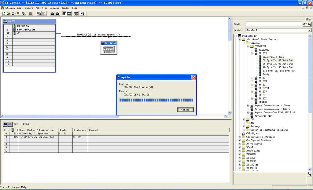
40 9. Configure - to PROFIBUS Network, and map the I/O module to S7-300 or other controller s memory. Move the data block to the left and down table. Operation include two steps. The first step is moving - to the left and up area, (PROFIBUS-DP bus), the mouse will change sharp, it means you can move it in. The second step is moving data to left and down data mapping table, (PLC memory). Note: Number of - can be 32-byte input and output, 96-byte input and output, 48-byte input and output and 112-byte input and output. If the gateway is configured to 48 bytes input / output in Hyper Terminal or DeviceNet configuration interface, you need take "48 Byte In, 48 Byte Out" into the data mapping table. If you drag the data block does not match the configuration of the gateway, PROFIBUS-DP connection can not be established. The factory configuration of number of bytes is "48 Byte In, 48 Byte Out". Note: Slave station s address should be the same with the setting of module s dial switches! 10. As shown above, right-click input and output mapping of the slot, set the relevant property, as shown below: 39

41 You can set input and output mapping area start address in the page. When the setting is 32 bytes input and output, the consistent is "Total length". 11. Compile and download the configuration to the PLC. 40
42 41
43 9 How Step7 read and write Gateway Data Data blocks which use Total Length as consistent are shown as follow: 2 Words Input Consistent 4 Words Input Consistent 8 Words Input Consistent 16 Words Input Consistent 2 Words Output Consistent 4 Words Out put Consistent 8 Words Out put Consistent 16 Words Out put Consistent In the Step7 program, you need use SFC15 (packaged sent) send data and use SFC14 (packaged receiver) receive data. SFC14 SFC15 Data blocks which use Words as consistent are shown as follow: 42


44 In Step7 program, you can use MOVE instruction read and write data. 43
45 10 Installation 10.1 Mechanical Size Size: 40mm (Width) 125mm (Height) 110mm (Depth) 10.2 Installation 35mm DIN rail 44
Catalog 1 Product Overview General Important User Information About the Gateway Function Features Tec
 PROFIBUS DP / Modbus TCP Gateway EP-321MP User Manual REV 1.2 Sibotech Automation Co., Ltd Technical Support: 021-5102 8348 E-mail:support@sibotech.net Catalog 1 Product Overview... 4 1.1 General...4 1.2
PROFIBUS DP/CAN Gateway PCA-100. User Manual
 PCA-100 REV 4.0 SiboTech Automation Co., Ltd. Technical Support: 021-5102 8348 E-mail: support@sibotech.net Catalog 1 Introduction... 2 1.1 About This Instruction... 2 1.2 Copyright... 2 1.3 Related Products...
Modbus/ PROFIBUS DP Gateway PM-160
 Modbus/ PROFIBUS DP Gateway PM-160 REV 3.2 SiboTech Automation Co., Ltd. Technical Support: +86-21-5102 8348 E-mail: support@sibotech.net Table of Contents 1 About This Document... 3 1.1 General... 3 1.2
Universal Serial/PROFIBUS DP Gateway GT200-DP-RS User Manual V6.1 SST Automation
 GT200-DP-RS V6.1 SST Automation E-mail: SUPPORT@SSTCOMM.COM WWW.SSTCOMM.COM Catalog 1 About the Gateway...4 1.1 Product Function...4 1.2 Product Features... 4 1.3 Technical Specifications... 4 1.4 Related
D0 DEVNETS and Allen Bradley Set up. RSNetworx
 D0 DEVNETS and Allen Bradley Set up RSNetworx G 2 Setup D0 DEVNETS with Allen Bradley RSNetWorx For those who are using the D0 DEVNETS as a slave with an Allen Bradley PLC, the examples on the following
BridgeWay. PROFIBUS to DeviceNet Gateway User Manual. Part No. AB7605. Publication PUB-AB
 BridgeWay PROFIBUS to DeviceNet Gateway User Manual Part No. AB7605 Pyramid Solutions 1850 Research Drive, Suite 300 Troy, Michigan 48083 Phone 248-524-3890 Web www.pyramid-solutions.com Publication PUB-AB7605-005
Embedded Modbus TCP Module GS11-MT. User Manual REV 1.1. SST Automation.
 Embedded Modbus TCP Module GS11-MT User Manual REV 1.1 SST Automation E-mail: SUPPORT@SSTCOMM.COM WWW.SSTCOMM.COM Catalog 1 About the Embedded Module... 4 1.1 General...4 1.2 Features... 4 1.3 Specifications...4
CVIC II - CVIL II - CVIR II - MULTICVIL II - Memory Mapping - Manual
 1/36 CVIC II - CVIL II - CVIR II - MULTICVIL II - Memory Mapping - Manual N - Copyright 2011, St Herblain France All rights reserved. Any unauthorized use or copying of the contents or part thereof is
HART / EtherNet/IP Gateway GT200-HT-EI User Manual V 1.0 REV A SST Automation
 HART / EtherNet/IP Gateway GT200-HT-EI V 1.0 REV A SST Automation E-mail: SUPPORT@SSTCOMM.COM WWW.SSTCOMM.COM Catalog 1 Product Overview... 4 1.1 Product Function...4 1.2 Product Features... 4 1.3 Technical
L5351 DeviceNet Communications Interface
 L5351 DeviceNet Communications Interface Technical Manual HG353798 Issue 2 Copyright SSD Drives, Inc 2005 All rights strictly reserved. No part of this document may be stored in a retrieval system, or
HART/ Modbus TCP Gateway GT200-HT-MT User Manual V 1.2 REV A SST Automation
 HART/ Modbus TCP Gateway GT200-HT-MT User Manual V 1.2 REV A SST Automation E-mail: SUPPORT@SSTCOMM.COM WWW.SSTCOMM.COM Catalog 1 Product Overview... 4 1.1 Product Function...4 1.2 Product Features...
SST Automation
 EtherNet / CAN Gateway GT200-MT-CA REV 1.0 SST Automation E-mail: SUPPORT@SSTCOMM.COM WWW.SSTCOMM.COM Catalog 1 About This Document... 4 1.1 General...4 1.2 Important Information... 4 1.3 Related Products...
PAC BI-DP BIM and 8701-CA-BI Carrier
 June 2013 PAC8000 8507-BI-DP BIM and 8701-CA-BI Carrier PROFIBUS DP Bus Interface Module and Carrier The 8507-BI-DP Bus Interface Module (BIM) provides the communications link between the PAC8000 series
LB/FB8X09* / LB/FB8X05*
 GETTING STARTED Connecting Remote I/O Stations with Com Unit LB/FB8X09* / LB/FB8X05* to Siemens PLC (S7-300) via PROFIBUS 1 Contents 1. INTRODUCTION... 3 2. PREPARING FOR CONFIGURATION... 3 2.1. DOWNLOADING
RMx621. Appendix to the operating manual
 Appendix to the operating manual RMx621 DP-slave module ( PROFIBUS-coupler ) from V2.01.00 Connecting the RMx621 to PROFIBUS DP via the RS485 serial interface using the external module (HMS AnyBus Communicator
DVPPF02-SL PROFIBUS DP Slave Communication Module
 DVPPF02-SL PROFIBUS DP Slave Communication Module Operation Manual DVP-0155320-01 Warning This operation manual provides introduction on the functions, specifications, installation, basic operation, settings
RMx621 /FML621. Appendix to the operating manual
 Appendix to the operating manual RMx621 /FML621 DP-slave module ( PROFIBUS-coupler ) from V2.01.00 Connecting the RMx621 /FML621 to PROFIBUS DP via the RS485 serial interface using the external module
FAQ Communication over PROFIBUS
 FAQ Communication over PROFIBUS Communication over PROFIBUS FAQ Table of Contents Table of Contents... 2 Question...2 How do I configure a PC station as DP Slave interfacing to a S7 station (as DP Master)
MPCR Series DeviceNet Technical Manual TDMPCRDNTM2-0EN 01/08 Subject to change without notice
 MPCR Series DeviceNet Technical Manual Table of Contents MPCR Series Introduction... 3 Product Overview... 3 About DeviceNet... 4 Overview... 4 MPCR DeviceNet Features... 4 Cabling and Drop Line Lengths
i-7550 PROFIBUS to RS-232/422/485 Converter User's Manual High Quality, Industrial Data Acquisition, and Control Products
 i-7550 PROFIBUS to RS-232/422/485 Converter User's Manual High Quality, Industrial Data Acquisition, and Control Products i-7550 PROFIBUS to RS-232/422/485 Converter User's Manual (Version 1.01) PAGE:1
Connecting UniOP to Simatic S7 Profibus
 Connecting UniOP to Simatic S7 Profibus This Technical Note contains all the information required to connect the UniOP panels to a Profibus DP system with a Simatic S7 master and to take advantage from
FACTORY AUTOMATION MANUAL CBX500 HOST INTERFACE MODULES
 FACTORY AUTOMATION MANUAL CBX500 HOST INTERFACE MODULES HOST INTERFACE MODULES With regard to the supply of products, the current issue of the following document is applicable: The General Terms of Delivery
Operating Instructions. Modules Fieldbus
 Operating Instructions Modules Fieldbus Leer Table of Content 1 Introduction... 5 1.1 General... 5 1.2 Compatibility... 6 1.3 Related Documentation... 6 1.4 Internet addresses... 6 2 Functional Overview...
Product Specification for CANbus to DeviceNet Transducer Gateway
 XG CANbus to DeviceNet Transducer Gateway April, 00 Product Specification for CANbus to DeviceNet Transducer Gateway The XG CANbus to DeviceNet Temposonics Gateway gathers position information from as
2002 Series DeviceNet Technical Manual
 2002 Series DeviceNet Technical Manual Table of Contents 2002 Series DeviceNet Technical Manual 2002 Introduction...4 Product Overview...4 About DeviceNet...5 Overview...5 2002 DeviceNet Features...5 Cabling
HART/ MODBUS Gateway HTM-611. User Manual REV
 HAT/ MODBUS Gateway HTM611 EV 1.6 SiboTech Automation Co., Ltd. Technical Support: +86215102 8348 Email: support@sibotech.net HAT/ Catalog 1 Product Overview... 4 1.1 Product Function... 4 1.2 Product
12.3 Fieldbus I/O Board
 12.3 Fieldbus I/O Board 12.3.1 Overview of Fieldbus I/O The Fieldbus I/O option is an option to add fieldbus slave function (DeviceNet, PROFIBUS-DP, CC-Link, EtherNet/IP) to the robot Controller. A fieldbus
SBPC-21-PB FifeNet to Profibus Gateway
 Fife Corporation PO Box 26508, Oklahoma City, OK 73126, U.S.A. Phone: 405.755.1600 / Fax: 405.755.8425 www.fife.com / E-mail: fife@fife.com SBPC-21-PB FifeNet to Profibus Gateway Profibus Operation Manual
Gateway 1400 Reference Manual
 Profibus-DP Gateway 1400 Reference Manual Copyright All Rights Reserved. No part of this document may be copied, reproduced, republished, uploaded, posted, transmitted, distributed, stored in or introduced
DSC FIELDBUS MODULES...
 DSC FIELDBUS MODULES SUMMARY DSC FIELDBUS MODULES... 1 INTRODUCTION... 2 ELECTRICAL CONNECTIONS... 2 PROTOCOL DATA PACKAGE COMPOSITION... 3 Footprint in input... 4 Footprint in output... 4 MV MODULES INPUT
The PROFIBUS and PROFINET Company. COMbricks Modules. Copyright 2013 PROCENTEC. All rights reserved.
 Modules SCOPE Repeater Module Name 1 Channel RS 485 SCOPE Repeater Type 1 Order code 101 201210 Description 1 Channel RS 485 PROFIBUS SCOPE repeater module with integrated quality oscilloscope for 12 Mbps
GW-7553-CPM PROFIBUS/CANopen GATEWAY. User's Manual
 GW-7553-CPM PROFIBUS/CANopen GATEWAY User's Manual High Quality, Industrial Data Acquisition, and Control Products GW-7553-CPM PROFIBUS/CANopen GATEWAY User Manual (Version 1.00, Apr/2016) PAGE: 1 Warranty
BridgeWay PROFIBUS to DeviceNet Gateway User Manual
 BridgeWay PROFIBUS to DeviceNet Gateway User Manual Part No. AB7605 For Firmware Revision 2.01.01 and Later Pyramid Solutions, Inc. 30200 Telegraph Road, Suite 440 Bingham Farms, MI 48025 www.pyramidsolutions.com
DN120 DeviceNet Gateway User Manual
 DN120 DeviceNet Gateway User Manual DN120 PN 84-210010 Rev A Table of Contents CHAPTER 1 OVERVIEW... 4 CHAPTER 2 INSTALLATION... 5 MOUNTING... 5 WIRING... 6 DeviceNet Interface... 6 Serial Channel Interface...
DeviceNet Communications
 DeviceNet Communications For PanelView Plus and PanelPlus CE Terminals 2711P User Manual Important User Information Solid state equipment has operational characteristics differing from those of electromechanical
MPCR Series DeviceNet Technical Manual
 MPCR Series DeviceNet Technical Manual Table of Contents MPCR Series Introduction...3 Product Overview...3 About DeviceNet...4 Overview...4 MPCR DeviceNet Features...4 Cabling and Drop Line Lengths (as
SMART RELAY SRW 01 V4.0X
 Motors Automation Energy Transmission & Distribution Coatings SMART RELAY SRW 01 V4.0X Profibus DP Communication Manual Profibus DP Communication Manual Series: SRW 01 Firmware Version: V4.0X Language:
PISO-DNS100 DeviceNet Multi-Slave PCI board Quick Start User Guide
 PISO-DNS100 DeviceNet Multi-Slave PCI board Quick Start User Guide 1. Introduction This Quick Start User Guide introduces users how to implement the PISO-DNS100 PCI board to your application quickly. Therefore,
EQ7000. User Manual. Rev 1.00
 EQ7000 User Manual Rev 1.00 www.equustek.com Revision 1.00 February 27, 2009 Contents INTRODUCTION...4 ABOUT THIS MANUAL...4 INTENDED AUDIENCE...4 HARDWARE SPECIFICATIONS...5 PHYSICAL SPECIFICATIONS...5
Driver Manual (Supplement to the FieldServer Instruction Manual) FS X30 DeviceNet Master Adapter Driver
 FS X30 DeviceNet Master Adapter Driver") A Sierra Monitor Company Driver Manual (Supplement to the FieldServer Instruction Manual) FS-8700-114 X30 DeviceNet Master Adapter Driver APPLICABILITY & EFFECTIVITY Effective for all systems manufactured
A Sierra Monitor Company Driver Manual (Supplement to the FieldServer Instruction Manual) FS-8700-114 X30 DeviceNet Master Adapter Driver APPLICABILITY & EFFECTIVITY Effective for all systems manufactured
Profibus Gateway 3E V Technical Bulletin
 Profibus Gateway 3E V1.0.0 Technical Bulletin TECHNICAL BULLETIN 2 Profibus Gateway 3E Liability for errors and misprints excluded. V1.0.0en/23.06.16 TECHNICAL BULLETIN Profibus Gateway 3E V1.0.0en/23.06.16
Operating Instructions. Modules Fieldbus
 Operating Instructions Modules Fieldbus Leer Table of Content 1 Introduction... 6 1.1 General... 6 1.2 Compatibility... 7 1.3 Related documentation... 7 1.4 Internet addresses... 7 2 Functional Overview...
How to Configure DeviceNet with Anybus Configuration Manager (ACM) for DeviceNet APPLICATION NOTE DRAFT
 for DeviceNet APPLICATION NOTE DRAFT") How to Configure DeviceNet with Anybus Configuration Manager (ACM) for DeviceNet APPLICATION NOTE ENGLISH Important User Information Liability Every care has been taken in the preparation of this document.
How to Configure DeviceNet with Anybus Configuration Manager (ACM) for DeviceNet APPLICATION NOTE ENGLISH Important User Information Liability Every care has been taken in the preparation of this document.
Features and Benefits. Certifications
 MGate 5111 Series 1-port Modbus/PROFINET/EtherNet/IP to PROFIBUS slave gateways Features and Benefits Protocol conversion between Modbus, PROFINET, EtherNet/IP, and PROFIBUS Supports PROFIBUS DP V0 slave
Configuration for General DIP Devices. Setting Up RSLinx
 Configuration for General DIP Devices Setting Up RSLinx Start Up RSLinx Program. Go to Communications Configure Drivers. Then, select an Available Driver Type (example, DeviceNet drivers). Once the appropriate
# Byrne Rd, Burnaby, BC, V5J 3J1, Canada Phone: or
 EQ7000 User Manual Rev 1.04 www.equustek.com Revision 1.04 Feb 20th, 2017 #286-5489 Byrne Rd, Burnaby, BC, V5J 3J1, Canada Phone: 888-387-3787 or 604-266-8547 www.equustek.com Page 1 Contents INTRODUCTION...4
R7D-RR8 BEFORE USE... POINTS OF CAUTION. INSTRUCTION MANUAL REMOTE CONTROL RELAY CONTROL MODULE, 8 points MODEL. (DeviceNet)
") INSTRUCTION MANUAL REMOTE CONTROL RELAY CONTROL MODULE, points (DeviceNet) MODEL BEFORE USE... Thank you for choosing M-System. Before use, please check contents of the package you received as outlined
INSTRUCTION MANUAL REMOTE CONTROL RELAY CONTROL MODULE, points (DeviceNet) MODEL BEFORE USE... Thank you for choosing M-System. Before use, please check contents of the package you received as outlined
Industrial Serial Device Server
 1. Quick Start Guide This quick start guide describes how to install and use the Industrial Serial Device Server. Capable of operating at temperature extremes of -10 C to +60 C, this is the Serial Device
TECHNICAL NOTE TNPC07
 TECHNICAL NOTE TNPC07 Title: Configuring a DLCN DeviceNet card with an AB 1747-SDN Scanner Card RLC Product(s): DLCN This Technical Note should be used with the Red Lion Controls Product Bulletin DLCN,
Document Name: User Manual for SC10MK, Modbus RTU to Modbus TCP Converter
 Document Name: User Manual for SC10MK, Modbus RTU to Modbus TCP Converter Login for the first time, please use http://192.168.1.100 To key in user name and password is for identifying authorization. Default
TECHNICAL NOTE TNDA05
 TECHNICAL NOTE TNDA05 Title: Configuring a PAXCDC30 DeviceNet card with an AB 1747- SDN Scanner Card RLC Product(s): PAXCDC30 This Technical Note is intended to be used along with the Red Lion Controls
Start-up of IRI-KHD2-4HB6, IRI-KHA6-4HB6 at S7-300 V1.2. Table of Contents TABLE OF CONTENTS... 1
 Table of Contents TABLE OF CONTENTS... 1 1. DESCRIPTION OF HARDWARE... 2 1.1 Modules and devices... 2 1.2 Set-up and installation... 2 2. HARDWARE CONFIGURATION... 2 2.1 Installation of the GSE file...
FC8x. Profibus Communication
 Title FC8x Profibus Communication SIEB & MEYER AG Auf dem Schmaarkamp 21 * D-21339 Lüneburg * (Germany) Telephone: +49-4131 - 203-0 * Telefax: +49-4131 - 203-2000 Email: documentation@sieb-meyer.de Internet:
Connection Procedure of WAGO CANopen Bus Coupler and Pro-face AGP-3****-CA1M/LT. Instruction Manual. Version1.1 (
 Connection Procedure of WAGO CANopen 750-337 Bus Coupler and Pro-face AGP-3****-CA1M/LT Instruction Manual Version1.1 (2013.11.01) Copyright 2008 by WAGO Kontakttechnik GmbH All rights reserved. WAGO Kontakttechnik
USER MANUAL FOR FIOA-0402-U-16
 USER MANUAL FOR FIOA-0402-U-16 COPYRIGHT NOTICE This manual is a publication of Renu Electronics Pvt. Ltd. and is provided for use by its customers only. The contents of the manual are copyrighted by Renu
Products for DeviceNet
 Four-port DeviceNet Gateways WRC is one of the original members of ODVA Your source for Blue-Collar Electronics. W5-JDC4 The W5-JDC4 is a DeviceNet-to-serial link communications gateway that provides a
ELC-CODNETM. Effective December Users Manual
 Effective December Users Manual Introduction This is an OPEN-TYPE device and therefore should be installed in an enclosure free of airborne dust, excessive humidity, shock and vibration. The enclosure
While every effort was made to verify the following information, no warranty of accuracy or usability is expressed or implied.
 AG090115 How to configure SIMATIC STEP7 V5.5 to read cyclic data from Objective: To use Siemens SIMATC S7300 PLC to read data from MultiRanger/HydroRanger 200 HMI through SmartLinx PROFIBUS communication
Operation manual. HDOM-Profibus-V0. More options please visit;www.veikong-electric.com
 Operation manual HDOM-Profibus-V0 More options please visit;www.veikong-electric.com Contents 1 Introduction... 1 1.1 Product description... 1 1.2 HDOM-Profibus-V0 label... 1 1.3 Technical specifications...
Profibus Getting Started User's Manual
 www.infoplc.net Profibus Getting Started User's Manual Version: 1.00 (July 2006) Model No.: MAPBGETST-ENG We reserve the right to change the contents of this manual without warning. The information contained
Modbus/DeviceNet Gateway MD-210 User Manual
 Modbus/DeviceNet Gateway MD-210 EV 1.2 April,2009 Sibotech Automation Co., Ltd Technical Support: +86-021-5102 8348 E-mail: support@sibotech.net Table of Contents 1 About This Document...4 1.1 General...
1782-JDC DeviceNet/Serial Gateway User s Manual
 1782-JDC DeviceNet/Serial Gateway User s Manual Western Reserve Controls, Inc. Although every effort has been made to insure the accuracy of this document, all information is subject to change without
PB IL 24 BK DIO 16/16
 PROFIBUS-DP/V1 Bus Coupler Station With 16 Digital Inputs and 16 Digital Outputs Data Sheet 643701 07/2003 $ "! % * This data sheet is only valid in association with the "Configuring and Installing the
L5353 Profibus-DP Communications Interface
 L5353 Profibus-DP Communications Interface Technical Manual HA470380 Issue 2 Copyright SSD Drives, Inc 2005 All rights strictly reserved. No part of this document may be stored in a retrieval system, or
Motors Automation Energy Transmission & Distribution Coatings. Profibus DP SRW 01. User s Manual
 Motors Automation Energy Transmission & Distribution Coatings Profibus DP SRW 01 User s Manual Profibus DP User s Manual Series: SRW 01 Firmware Version: V6.0X Language: English Document Number: 10000521541
EL731 PROFIBUS INTERFACE
 Tel: +1-800-832-3873 E-mail: techline@littelfuse.com www.littelfuse.com/el731 EL731 PROFIBUS INTERFACE Revision 0-A-032816 Copyright 2016 Littelfuse Startco All rights reserved. Document Number: PM-1011-EN
Murdoch University Engineering Thesis. Appendix XII. Profibus PA System Configuration Instructions
 Appendix XII Profibus PA System Configuration Instructions Author: Hao Xu Page: p8 - p Last modified: // This is part of the Engineering Thesis WinCC SCADA System via Profibus & OPC by Hao Xu. 8 P a g
TECHNICAL NOTE TNOI36
 TECHNICAL NOTE TNOI36 Title: DeviceNet TM Slave Communication Product(s): G3, Modular Controller Enhanced Master and DSP ABSTRACT The purpose of this document is to describe the G3 s support for DeviceNet
GW-7238D J1939 to Modbus TCP Server / RTU Slave Gateway
 GW-7238D J1939 to Modbus TCP Server / RTU Slave Gateway User s Manual www.icpdas.com 1 Warranty All products manufactured by ICP DAS are under warranty regarding defective materials for a period of one
01348(N or G) MH** -- Material Handling (N or G) MH** -- Material Handling
 MH** -- Material Handling (N or G) MH** -- Material Handling") MATERIAL HANDLING MANIFOLDS WITH DeviceNet INTERFACE 01348(N or G) MH** -- Material Handling 01351(N or G) MH** -- Material Handling Note: N = NPT ports G = BSPP ports SOL 14 SOL 12 Station #3 SOL 14 SOL
MATERIAL HANDLING MANIFOLDS WITH DeviceNet INTERFACE 01348(N or G) MH** -- Material Handling 01351(N or G) MH** -- Material Handling Note: N = NPT ports G = BSPP ports SOL 14 SOL 12 Station #3 SOL 14 SOL
CAN 300 PRO, Communication Module
 90 Communication Modules CAN 300 PRO, Communication Module Layer 2, 11 Bit and 29 Bit (CAN 2.0 A/B) on the module DIP switch for adress + baud rate Micro Memory Card for saving a project (optional) USB
INSTRUCTION MANUAL WCS-Interface Module, DeviceNet
 FACTORY AUTOMATION INSTRUCTION MANUAL WCS-Interface Module, DeviceNet WCS-DG210 Part. No. 202340 / DOCT-1305 / 11. june 2007 1 Working principle............................ 6 2 Installation and commissioning.................
FieldServer FS DeviceNet Slave Adapter Driver
 FieldServer FS-8700-22 DeviceNet Slave Adapter Driver Driver Manual (Supplement to the FieldServer Instruction Manual) APPLICABILITY & EFFECTIVITY Effective for all systems manufactured after December
FC 300 DeviceNet and Allen Bradley Control logix 5550
 Introduction... 2 FC 300 DeviceNet card... 2 Creation of an EDS file... 4 Configuring the FC 300 with RS Networx... 7 I/O communication with RS Logix 5000... 1 0 Explicit messages with RS Logix 5000...
How to configure a PROFIBUS network with NetTool for PROFIBUS
 How to configure a PROFIBUS network with NetTool for PROFIBUS www.anybus.com HMS Industrial Networks AB Page 1 (25) Document history Revision Date Description Responsible 1.00 2005-04-14 Created Patrik
User Guide AnyBus NetTool for DeviceNet
 User Guide AnyBus NetTool for DeviceNet Rev. 1.00 HMS Industrial Networks Germany Japan Sweden U.S.A + 49-721 - 96472-0 + 81-45 - 478-5340 + 46-35 - 17 29 20 + 1-773 - 404-2271 sales-ge@hms-networks.com
USB to RS-232/RS422/485. US-101-I USB To Serial Operation Manual
 USB to RS-232/RS422/485 US-101-I USB To Serial Operation Manual First Edition, Jun 2008 Table of Contents 1. Introduction 2 2. Package checklist 3 3. Product Specification 4 4. Product Panel Views Description
I-7565-DNM USB / DeviceNet Master Module Quick Start Manual
 I-7565-DNM USB / DeviceNet Master Module Quick Start Manual 1. Introduction This quick start manual introduces users how to implement the I-7565-DNM module to their application quickly. Therefore, it is
Additional instructions Memograph M, RSG45 Advanced Data Manager
 BA01414R/09/EN/01.15 No.: 71302193 Firmware version ENU000A, V2.00.xx Products Solutions Services Additional instructions Memograph M, RSG45 Advanced Data Manager PROFIBUS DP slave Table of contents: 1
VersaMax* IC200BEM003. PROFIBUS Master Module. Ordering Information. Specifications. GFK-2739 April of their respective owners.
 April 2012 The VersaMax * IC200BEM003 PROFIBUS Master Module allows a VersaMax CPU005, CPUE05 or PROFINET Scanner (PNS) to send and receive data on a PROFIBUS-DP V1 network. The PROFIBUS Master module
VPGate Manual PROFIBUS to serial
 VPGate Manual PROFIBUS to serial Important information Purpose of the Manual This user manual provides information how to work with the VPGate PROFIBUS to serial. Document Updates You can obtain constantly
FieldServer FS DeviceNet Master Adapter Driver
 FieldServer FS-8700-114 DeviceNet Master Adapter Driver Driver Manual (Supplement to the FieldServer Instruction Manual) APPLICABILITY & EFFECTIVITY Effective for all systems manufactured after March 2017.
Anybus-CC CFW-11. User s Manual. Phone: Fax: Web: -
 Anybus-CC CFW-11 User s Manual Anybus-CC User s Manual Series: CFW-11 Language: English Document Number: 0899.5750 / 06 Publication Date: 09/2013 CONTENTS CONTENTS... 3 ABOUT THE MANUAL... 6 ABBREVIATIONS
MGate 5111 Quick Installation Guide
 MGate 5111 Quick Installation Guide Edition 1.0, December 2017 Technical Support Contact Information www.moxa.com/support Moxa Americas: Toll-free: 1-888-669-2872 Tel: 1-714-528-6777 Fax: 1-714-528-6778
Product Specification
 Product Specification MLC 9000+ Basic Bus Module The Basic Bus Module is part of the MLC 9000+ DIN-Rail mounting multiple loop PID control system. The Basic Bus Module is the supervisor in the MLC 9000+
Products for DeviceNet
 Four-port DeviceNet Gateways W5-JDC4 The W5-JDC4 is a DeviceNet-to-serial link communications gateway that provides a flexible DeviceNet interface to as many as four different channels of ASCII devices.
SIMATIC S7 MPI Direct Driver
 Siemens AG SIMATIC S7 MPI Direct Driver 1 System Configuration... 3 2 Selection of... 5 3 Example of Communication Setting... 6 4 Setup Items...13 5 Cable Diagram... 18 6 Supported Device... 25 7 Device
DeviceNet Conformance Test Result
 DeviceNet Conformance Test Result Test Date: 07 June 2004 Composite Test Revision: 18 Test Suite: M002 ODVA File Number: 10105 Vendor ID: 706 Vendor Name: Bronkhorst High-Tech B.V. Vendor Address: Nijverheidsstraat
Motortronics VirtualSCADA VS2-MT Communication Gateway VS2-MT User Manual Revision
 Motortronics VirtualSCADA VS2-MT Communication Gateway VS2-MT User Manual Revision 1.03.00 Motortronics / Phasetronics 1600 Sunshine Drive Clearwater, Florida 33765 Tel: 727-573-1819 Fax: 727-573-1803
Output Interfaces for SVS2000 TM Installation & Operation Manual
 IOM Output Interfaces for SVS2000 TM Installation & Operation Manual Output Interfaces for SVS2000 TM Installation & Operation Manual CONTENTS I. INTRODUCTION... 1 II. INSTALLING THE OUTPUT INTERFACE...
GE FANUC Parts 1. DeviceNet Network Master/Slave August 2002 GFK-1539A. Quick Start Guide. Product Description. Specifications. Preinstallation Check
 Product Description Revision Letter: BA Firmware version: 1.10 Firmware upgrades: DeviceNet Certification: Product Name: None Certificate available upon request. DeviceNet Network Control Module (NCM)
Canlan INSTALLATION MANUAL
 Canlan INSTALLATION MANUAL August 2014 Table of Contents Introduction... 4 Overview... 5 RJ45 Connector and Status LEDs... 5 Power Input... 6 RS232 / RS485 Connectors... 7 Installing the Canlan Software...
SK CU4-PBR-C Part number:
 SK CU4-PBR-C Part number: 275 271 500 PROFIBUS DP Internal Bus Interface The bus interface may only be installed and commissioned by qualified electricians. An electrician is a person who, because of their
eloprog 485EPF.. - Vers. 1.2 eloprog Configurable safety system FIELD BUS MODULES
 eloprog 485EPF.. - Vers. 1.2 eloprog Configurable safety system FIELD BUS MODULES 1 List of contents INTRODUCTION 3 ELECTRICAL CONNECTIONS 3 PROTOCOL DATA PACKAGE COMPOSITION 4 DIAGNOSTICS 6 The "I/O index"
I-7550E PROFIBUS/Ethernet Converter. User's Manual
 I-7550E PROFIBUS/Ethernet Converter User's Manual High Quality, Industrial Data Acquisition, and Control Products I-7550E PROFIBUS/Ethernet Converter User Manual (Version 100, June/2014) PAGE: 1 Warranty
How to configure and connect the Alpha Gateway Interface to a DeviceNet network
 How to configure and connect the Alpha Gateway Interface to a DeviceNet network Contents Technical support............. 1 Introduction................. 1 Basic setup procedure.......... 2 Related documents............
Driver Manual. FS DeviceNet Master Adapter Driver
 A Sierra Monitor Company Driver Manual (Supplement to the FieldServer Instruction Manual) FS-8700-114 DeviceNet Master Adapter Driver APPLICABILITY & EFFECTIVITY Effective for all systems manufactured
User Manual A08. User Manual
 A08 TABLE OF CONTENTS TABLE OF CONTENTS... 1 1. INTRODUCTION... 2 1.1. Key Features... 3 1.2. OS Requirement... 4 1.3. Specification... 4 1.4. Packing List... 4 2. OVERVIEW... 5 2.1. LED Definition...
SK TU4-PBR Part number:
 SK TU4-PBR Part number: 275 281 100 PROFIBUS DP External Bus Interface The bus interface may only be installed and commissioned by qualified electricians. An electrician is a person who, because of their
DeviceNet Drive Profile CFW-09
 Motors Automation Energy Transmission & Distribution Coatings DeviceNet Drive Profile CFW09 Communication Manual DeviceNet Drive Profile Communication Manual Serie: CFW09 Language: English Software Version: