Touch Sense Controller
|
|
|
- Logan Singleton
- 5 years ago
- Views:
Transcription
1 Touch Sense Controller Paul Boston May 11, 2011 (Modified May 22, 2014) (Modified Dec 28, 2015) The Touch Sense Controller is a microprocessor-controlled circuit designed to provide a switch closure when the touch-sensing pad is touched. The microprocessor senses reflected IR from a sensor located slightly below the Hand and activates a relay to provide both an indication of the touch and an independent switch operation. Power to the control board may be either AC or DC at voltages between 9 and 15 volts. It is highly recommended that a wall wart 12 volt supply be used which will keep the power leads as short as possible. Longer power cables seem to cause erratic behavior, but experience will dictate the installation choices. The circuit board contains a red LED as a necessary part of the power supply. This will indicate that power is being supplied to the entire board. The tally connection is a three-pin connection conditioned to accept a bi-color LED to indicate when the touch sensor has been activated. This allows calibration of the unit after installation. As supplied the touch sense is programmed to hold the on-board relay in the energized state for approximately five (5) seconds after a touch is sensed. During that time the touch pad is ignored by the microprocessor. The relay has two independent contact sets (DPDT) that provide both normally closed and normally open connections. One set of contacts is dedicated to the tally LED while the other set of contacts may be used for any load up to 2 amps.

2 Connections: Power is supplied through a two-pin connector on the top right of the board and labeled as power. Power may be AC or DC and polarity is not important. The status indicator is to be a three wire bicolor LED and is connected with the cathode to the center pin and the anodes connected to the outer pins. The three-pin connector on the top of the board is labeled Tally The touch pad is connected to the circuit board with a cable that is hard wired to the circuit board. (The two-pin connector on the top of the circuit board and labeled Sense and the Trim Pot are no longer used). The 3.5mm stereo plug located on the top left of the circuit board is for programming the PICXE 08M2 chip. See Picaxe.com for specifics. The five-pin connector located at the bottom of the board provides switch closure. The connections from left to right are: 1-Common 2-Unused 3-Normally Closed 4-Unused (Power Option) 5-Normally Open (There is an option that will allow the attached controlled device to be powered by the same power source that is attached to the top right of the board. To use this configuration solder jumper wires between the holes labeled J1 and J2. This links the input power to the Common pin #1 to one wire of the power input and the other wire to the (Power Option) pin #4. By connecting the device to be controlled to pins #3 and #4 the device will be powered whenever power is applied to the main power of the board. If the connection is made to pins #4 and #5 the device will be powered on only when the touch pad is touched)
.")
3 Modification 2. Dec 28, 2015 (PAB) Modifications were made to the circuit board in late 2015 allowing the IR sensor module to be plugged directly into the circuit board (Sensor Connect). Unlike the last modification the IR sensor does not need an in-line resistor to its IR LED. It has been provided for on the board (the resistor just above the Sensor Connector in the photo). The Tally LED is soldered directly to the circuit board eliminating the need to add a remote LED. Some of these board-c builds are still equipped with the 3-pin connector for a remote Tally indication.
4 The other upgrade has been to add the ability to use jumper pins rather than soldering wires to board holes J1 and J2 to provide power as described earlier. Jumper fitted to pins 1-2 (J1) and 3-4 (J2) will provide input power when the device is connected to pins 4 and either 3 or 5 of the Control. Pin 4 is directly connected to the input power while the NC (3-4) or NO (4-5) pins will be relay controlled and connected to the other leg of the power input. Note that whatever power, AC or DC, with voltage up to 25 V and current less than one amp, is provided to the input in the upper right of the board will go to the connected device. Expanded Uses: This board has now been incorporated into a train-detection role and has been installed to control the traffic indicators on the signal bridges. When used as a train detector the sensor is mounted between the ties alongside the center rail of the track with the sensor pointing up. The circuit board is located within the range of the sensor cable length and screwed to the bottom of the HDPE track bed. Power is supplied from any convenient source above 7 volts. Setup: Install the circuit board in a location that is easy to see and fairly close to both the power source and the touch pad. Two to three feet from each is adequate. Attach the bi-color LED to the Talley connector. A three-pin Molex on both ends of a three-wire cable will allow the LED to be inserted in one end and the cable attached to the circuit board with the other end. Again, keep the wire as short as practical since the LED is powered by the same power supply that runs the microprocessor and keeping electronic noise to a minimum is always desirable. Connect the in-line connector from the sensor board to the lead coming from the circuit board. Using a five-pin Molex connector connect the device to be controlled to the circuit board on the lower part of the board. The usual wire configuration is to use pins 1 and 5 for a normal switch closure. This provides a switch closure when the touch pad is touched. Use pins 1 and 3 if a switch opening is desired. See the above chart. Connect the power using a two-pin Molex connector to the pins labeled Power on the upper right of the board. Calibration: During manufacture small deviations in the build process makes each Hand slightly different in its response to touch, requiring mating the hand with the software on the board.
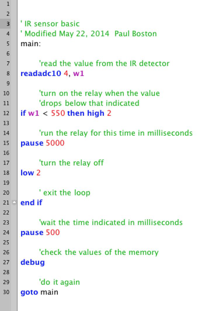
5 It is most convenient to calibrate the Hand sensitivity on the bench before installation. With the power on, confirm the red LED on the bottom right of the board is on. The Talley LED may be either red or green depending on which way it was installed in the holder. On power-up the microprocessor will run its installed program, so the touch pad will be active at all times. Touch the Touch Pad to see if the tally LED changes color. If it does change color it will return to the original color after five (5) seconds (or the programmed time). If this color change does not occur the threshold value in the program will need to be adjusted. This is NORMAL! Programming: The Touch Sense board uses a PicAxe 08M2 microprocessor. The Touch Sense board comes pre-programmed to operate the relay for five (5) seconds when a touch is sensed on the touch pad. The software and instructions needed to program the 08M2 is free and available on-line from PicAxe.com. The 3.5 mm stereo phone jack on the upper left of the board is a serial connection to a computer. It is recommended cable is the AXE027 as configured by PicAxe and available on-line. This cable uses the USB port and is wired to connect directly to the 3.5 mm stereo phone jack. The software from PicAxe is a form of BASIC which is compiled before being uploaded to the PicAxe chip. Below is the program installed on the Touch Sense board after assembly. When the program is uploaded it runs whenever power is present. The Debug line allows the programmer to observe the memory contents so that the sensitivity in line 12 can be adjusted.
6
Track Power Control. General:
 Track Power Control General: Track power is supplied by the transformers thru the TIUs mounted on five wiring panels located along the aisles and suspended from the layout facia. The power is then routed
UF-3701 Power Board Construction Guide
 Page 1/5 Soldering and Part Placement See the Chapter 3 of the MIT 6270 Manual for information on electronic assembly, including soldering techniques and component mounting. Construction Information All
Button Code Kit. Assembly Instructions and User Guide. Single Button Code Entry System
 Button Code Kit Single Button Code Entry System Assembly Instructions and User Guide Rev 1.0 December 2009 www.alan-parekh.com Copyright 2009 Alan Electronic Projects Inc. 1. Introduction... 4 1.1 Concept
TurboTaig Instruction Manual
 TurboTaig Instruction Manual Version: 2.2 Peter Homann 20 View St Highett 3190 homann@smartchat.net.au http://people.smartchat.net.au/~homann 1 Table of Contents Table of Contents... 2 Introduction...
Installation/assembly manual for DCC/Power shield
 Installation/assembly manual for DCC/Power shield The DCC circuit consists of the following components: R1/R6 R2/R3 R4/R5 D1 C2 2 kω resistor ½ Watt (colour code Red/Black/Black/Brown/Brown) 10 kω resistor
TEMPERATURE SENSOR/FAN CONTROL BOARD USER'S MANUAL
 Sample page from the Temperature Sensor/Fan Control User s Manual: TEMPERATURE SENSOR/FAN CONTROL BOARD USER'S MANUAL Introduction: The Temperature Sensor/Fan Control Board is a compact, free-standing
Sierra Radio Systems. Making a Keyer with the. HamStack. Project Platform
 Sierra Radio Systems Making a Keyer with the HamStack Project Platform Introduction The HamStack Project Board includes primary interface elements needed to make a high quality CW keyer. Using the LCD
AXE Stack 18. BASIC-Programmable Microcontroller Kit. An inexpensive introduction to microcontroller technology for all ability levels
 Ltd AXE Stack 18 BASIC-Programmable Microcontroller Kit a division of An inexpensive introduction to microcontroller technology for all ability levels Free Windows interface software Programmable in BASIC
Breadboard Voltage. Convenient 5V Supply for Breadboard
 Breadboard Voltage Regulator v2.1 Convenient 5V Supply for Breadboard Turn your 6~18VDC Wall Wart adapter into a regulated 5VDC @ 0.5 Ampere supply for your breadboard experiments! Build Time: 20mins Skill
STAGE INTERCOM KIT 1.1 SPECIFICATION. General: The lower section is a small power amplifier designed to drive headphones or a small 8ohm speaker.
 STAGE INTERCOM KIT Version 2.1.1 - March 2018 - EduTek Ltd 1.0 DESCRIPTION This intercom module comprises of two separate circuits sharing the same supply. The upper section is a pre-amplifier designed
Sierra Radio Systems. HamStack. Project Board Reference Manual V1.0
 Sierra Radio Systems HamStack Project Board Reference Manual V1.0 Welcome HamStack Project Board Reference Manual Revision 1.0.3 2011 George Zafiropoulos, KJ6VU and John Best, KJ6K This guide provides
FCB1010 Phantom Power Adaptor
 FCB1010 Phantom Power Adaptor The Behringer FCB1010 pedal is normally powered by an external cable that plugs into a standard 120 volt 3-prong wall receptacle. While this works fine, it does require a
PICAXE EXPERIMENTER BOARD (AXE090)
") (AXE00) Description: The PICAXE experimenter board allows circuits for any size/revision of PICAXE chip ( / / ) to be quickly tested using a prototyping breadboard. The experimenter board provides power
(AXE00) Description: The PICAXE experimenter board allows circuits for any size/revision of PICAXE chip ( / / ) to be quickly tested using a prototyping breadboard. The experimenter board provides power
GRBL SHIELD FOR ARDUINO UNO USER MANUAL
 GRBL SHIELD FOR ARDUINO UNO USER MANUAL YRCNC 2017 Introduction Thanks for supporting us! Hope you will have many hours of fun using this shield and that plenty hours of issueless cutting! The main features
INSTALLATION INSTRUCTIONS
 INSTALLATION INSTRUCTIONS MicroComm DXI MAI-425 Master Audio Interface. Intent & Scope This document describes the installation procedure for the MAI-425 Master Audio Interface. The earliest version of
What are output transducers An output transducer will convert electrical signals passed to it by the process into another form of energy.
 What are output transducers An output transducer will convert electrical signals passed to it by the process into another form of energy. ACTIVITY Can you find the symbols of the output components listed
MuP-VT. By Mick Gulovsen 11-Sep-2014 Ver. 1
 MuP-VT By Mick Gulovsen 11-Sep-2014 Ver. 1 bigmick58@bigpond.com Board Concept. MuP-VT is a small 49.5mm x 49.5mm PCB that is based on Geoff Graham s ASCII Video Terminal (AVT), which is a VT100 based
Universal Keying Adapter 3+
 Universal Keying Adapter 3+ The Universal Keying Adapter Version 3+ kit will allow you to key nearly any transmitter or transceiver with a straight key, electronic keyer, computer serial or parallel port
Blue Point Engineering
 Blue Point Engineering SV203 Interface Overview Overview Sensors Light Sensor Motion Sensor Joystick Computer USB PORT Technical Pointing the Way to Solutions! T http://www.bpesolutions.com Animatronic
AirTest Model CN9000 Series Sensor Controller
 AirTest Model CN9000 Series Sensor Controller AirTest Model CN9000 Series Sensor Controller THEORY OF OPERATION A basic CN9000 configuration consists of Input/Process/Display combination modules, a 3 relay
flight of harmony POWER Barebones Pack ~v1.0~
 flight of harmony POWER Barebones Pack ~v1.0~ fig.1 fig.2 + + + + Components 1 Assembled POWER PCB 1* 12VAC 1000mA wall adapter 1 13 18AWG DC power harness 1 DPDT power switch with hardware 1 2.1mm x 5.5mm
CONTROL PROTOCOL Motorized Projection Screens
 CONTROL PROTOCOL Motorized Projection Screens Table of Contents Overview... 3 Control Wiring Diagram... 3 IR Control... 4 Remote Button IR Hex Commands... 4 12 Volt DC Trigger... 5 Contact Closure and
MegaPoints Controllers Feedback Module.
 MegaPoints Controllers Feedback Module. 24 channel feedback module for version 2 MultiPanel Processors. User guide Features include No soldering truly plug and play Various sensor types o DCC and analogue
Assembly Instructions for the KA Electronics RIAA EQ Monitor Switcher
 Assembly Instructions for the KA Electronics RIAA EQ Monitor Switcher Install IC sockets EQ Monitor Switcher PC Board Stuffing Guide Place the PC Board on the bench silkscreen side face up. Drop eleven
Design Modular Planning
 Phys253 - Lecture 7, Part II Circuit Components & Layout Design Modular Planning Design by assembling simple circuit modules, such as filters or amplifiers Modules may be separated by buffers, where required
Connecting a Cisco Output Module
 CHAPTER 5 Overview The optional Cisco Output Module (Figure 5-1) is attached to a Cisco Physical Access Gateway or Cisco Reader Module to provide additional connections for up to 8 outputs, each of which
INSTALLATION INSTRUCTIONS
 INSTALLATION INSTRUCTIONS MicroComm DXI. Intent & Scope This document describes the installation procedure for the IMS-30 Intercom Master Station and the MAI-420 or MAI-20 Master Audio Interface. The earliest
Using Digitrax Devices on a Non Digitrax DCC Controlled Layout Rev. 3 By Elmer McKay < >
 Using Digitrax Devices on a Non Digitrax DCC Controlled Layout Rev. 3 By Elmer McKay < emckay70@member.afa.org > The following information was written to help the Non-Digitrax user; use, control, and interface
Butterfly Laser Diode Mount
 LM14S2 Butterfly Laser Diode Mount Operating Manual LM14S2 Laser On TEC Driver LD Driver THORLABS, Inc. Ph: (973) 579-7227 435 Route 206N Fax: (973) 383-8406 Newton, NJ 07860 USA www.thorlabs.com 10614-D02
8051 Intermidiate Development Board. Product Manual. Contents. 1) Overview 2) Features 3) Using the board 4) Troubleshooting and getting help
 Overview 2) Features 3) Using the board 4) Troubleshooting and getting help") 8051 Intermidiate Development Board Product Manual Contents 1) Overview 2) Features 3) Using the board 4) Troubleshooting and getting help 1. Overview 2. Features The board is built on a high quality FR-4(1.6
8051 Intermidiate Development Board Product Manual Contents 1) Overview 2) Features 3) Using the board 4) Troubleshooting and getting help 1. Overview 2. Features The board is built on a high quality FR-4(1.6
Connecting a Cisco Input Module
 CHAPTER 4 Overview The optional Cisco Input Module (Figure 4-1) is attached to a Cisco Physical Access Gateway or Cisco Reader Module to provide additional connections for up to ten input devices. Each
PN PSTK-120 PowerSwitch Tail 120vac Kit PN PSTK-240 PowerSwitch Tail 240vac Kit
 CAUTION: Please make sure you have or have access to the skills necessary to assemble and use this product. Always secure the case with the included screws before applying electrical power to the power
INSTALLATION INSTRUCTIONS. FST-420 Fiber Station Transceiver
 INSTALLATION INSTRUCTIONS MicroComm DXI Fiber Station Transceiver. Intent & Scope This document describes the installation procedure for the Fiber Station Transceivers. 2. Description The Fiber Station
Power Entry. Version 1.0 June 2, 2017
 Power Entry Version 1.0 June 2, 2017 1 Overview The Power Entry board is used for distributing AC power and 4 different DC voltages, generally 5v, 12v, 15v, and high voltage (typically 48v or 70v). A 12v
PICAXE DEVELOPMENT BOARD (AXE091)
") PICAXE DEVELOPMENT BOARD (AXE0) Description: The PICAXE development board allows circuits for any size/revision of PICAXE chip ( / / / 0 / / 0) to be quickly tested using a prototyping breadboard. The
PICAXE DEVELOPMENT BOARD (AXE0) Description: The PICAXE development board allows circuits for any size/revision of PICAXE chip ( / / / 0 / / 0) to be quickly tested using a prototyping breadboard. The
Shack Clock kit PCB Revision: QCU Rev 1 or QCU Rev 3
 1. Introduction Shack Clock kit PCB Revision: QCU Rev 1 or QCU Rev 3 Thank you for purchasing this QRP Labs Shack Clock kit. The kit uses the same PCB and bag of components as some other QRP Labs kits.
The Single Dimmer Board
 The Single Dimmer Board Introduction This electronic system has been designed as an interface unit between a Cronapress illuminated press strip and an external system such as a security alarm system; a
The Basic Counter. Hobby Electronics Soldering Kit. Instruction Guide
 The Basic Counter Hobby Electronics Soldering Kit Instruction Guide TM For the best outcome, follow each step in order. We recommend reading this guide entirely before you get started. Tools required:
PROGRAMMABLE MULTI-FUNCTION
 PROGRAMMABLE MULTI-FUNCTION DIP-Switch Digital-Set TD-8 Series time delay relays plug-in Sixteen user-selectable modes in one unit DIP-Switches for accurate digital set of time delay & selection of function
Delta T Dew Heater for CDK
 Delta T Dew Heater for CDK Delta T Dew Heater for CDK12.5 (125902) Your CDK 12.5 Delta T Dew Heater includes the following: QTY 1 Delta T control box w/ mounting bracket attached 1 2.5Amp AC adapter 2
PICAXE CONNECT (AXE210)
") PICAXE CONNECT (AXE10) Description: The AXE10 Connect board has been designed as a experimental project board for users wishing to learn how to interface a PICAXE chip to the Maxstream module or a LocSense
PICAXE CONNECT (AXE10) Description: The AXE10 Connect board has been designed as a experimental project board for users wishing to learn how to interface a PICAXE chip to the Maxstream module or a LocSense
CDN502 HIGH DENSITY I/O ADAPTER USER GUIDE
 CDN502 HIGH DENSITY I/O ADAPTER USER GUIDE 13050201 (c) Copyright DIP Inc., 1996 DIP Inc. P.O. Box 9550 MORENO VALLEY, CA 92303 714-924-1730 CONTENTS DN502 PRODUCT OVERVIEW 1 DN502 INSTALLATION 1 POWER
NETRONICS HS3500 CONTROLLER
 NETRONICS HS3500 CONTROLLER CUSTOMER NAME CONTROLLER SERIAL # CONTROLLER PART # PERSONALITY SWITCH SETTINGS BULLET PRESS CONFIGURATION DELIVERY DATE Contact the factory for help setting up your application.
Adafruit USB Power Gauge Mini-Kit
 Adafruit USB Power Gauge Mini-Kit Created by Bill Earl Last updated on 2017-07-14 11:55:04 PM UTC Guide Contents Guide Contents Overview Assembly Basic Assembly Solder the female connector. Solder the
Assembly Instructions for the KA Electronics IGFO Input Gain Filter Output Board
 Assembly Instructions for the KA Electronics IGFO Input Gain Filter Output Board IGFO PC Board Stuffing Guide Install IC sockets Place the PC Board on the work bench silkscreen side face up. Place ten
KAA Watt x 2 Class-D Audio Amplifier Kit
 KAA10021 50 Watt x 2 Class-D Audio Amplifier Kit This amplifier kit uses Texas Instruments TPA3116D2 stereo audio amplifier IC for driving speakers up to 50 watts @ 4 ohm per channel in stereo mode and
12v Power Controller Project Board
 12v Power Controller Project Board 12 Volt Power Controller Introduction This board provides three functions... DC power gate Low voltage disconnect Voltage / current display The typical usage for this
Sandevices E681 RGB Pixel Controller Assembly Manual
 Sandevices E681 RGB Pixel Controller Assembly Manual Oct 22, 2011 Oct 30, 2011 Initial Release Added component illustrations, silkscreen images, and misc text changes Prior electronic assembly experience
Lab 2.2 Ohm s Law and Introduction to Arduinos
 Lab 2.2 Ohm s Law and Introduction to Arduinos Objectives: Get experience using an Arduino Learn to use a multimeter to measure Potential units of volts (V) Current units of amps (A) Resistance units of
Arrakis Systems 6604 Powell Street / Loveland, Colorado 80538
 Arrakis Systems 6604 Powell Street / Loveland, Colorado 80538 Input and Output wiring for the 150sc, 500sc, 2000sc and 2100sc audio consoles. A Input Channel Wiring (Back of Console) 6. Left Input 5. Left
How-To #7: Assemble an H-bridge Circuit Board
 How-To #7: Assemble an H-bridge Circuit Board Making a DC motor turn is relatively easy: simply connect the motor's terminals to a power supply. But what if the motor is to be controlled by an Arduino,
Installation instructions DC Protection and Delay unit, Version 1.2 The package should contain: A piece of normal gauge yellow wire for the AC connect
 Installation instructions DC Protection and Delay unit, Version 1.2 How does the unit work? Delay: Basically a capacitor is charged via a resistor, when the voltage of the capacitor reach a certain level,
CV Arpeggiator Rev 2 Build Documentation.
 CV Arpeggiator Rev Build Documentation. Last updated 8-0-03 The CV Arpeggiator is a modular synth project used for creating arpeggios of control voltage. It utilizes a custom programmed PIC 6F685 micro
EE 354 August 1, 2017 Assembly of the AT89C51CC03 board
 EE 354 August 1, 2017 Assembly of the AT89C51CC03 board The AT89C51CC03 board comes as a kit which you must put together. The kit has the following parts: No. ID Description 1 1.5" x 3.25" printed circuit
Insert the male, 90 angled, 2x10 connectors into the corresponding 2x10 sockets and put them in place, flat under the PCB. Solder.
 MC624 Assembly guide Safety warning The kits are main powered and use potentially lethal voltages. Under no circumstance should someone undertake the realisation of a kit unless he has full knowledge about
Infrared Add-On Module for Line Following Robot
 1 Infrared Add-On Module for Line Following Robot January 3, 2015 Jeffrey La Favre The infrared add-on module allows multiple line following robots to operate on the same track by preventing collisions
Installing Sentor. Hardware Installation
 Remote base site monitoring and control Installing Sentor Hardware Installation Copyright 2000 Sentor Monitoring Systems Pty Ltd Contents: 1 Introduction... 1 2 Sentor GUI... 2 3 ST3000 Controller... 3
UCBB dual port breakout board user's manual
 UCBB dual port breakout board user's manual 1/14 Contents 1 Features 2 Dimensions 3 Connectors 3.1 Screw terminals 3.2 IDC ports 3.3 Powering 3.4 Outputs 3.5 Inputs 4 LED indicators 5 Example connections
High Power (15W + 15W) Stereo Amplifier
 Stereo Amplifier") High Power (15W + 15W) Stereo Amplifier Build Instructions Issue 1.0 Build Instructions Before you put any components in the board or pick up the soldering iron, just take a look at the Printed Circuit
High Power (15W + 15W) Stereo Amplifier Build Instructions Issue 1.0 Build Instructions Before you put any components in the board or pick up the soldering iron, just take a look at the Printed Circuit
ADDENDUM FOR 20, 27, & 28 OPTIONS
 ADDENDUM FOR 20, OPTIONS GENERAL The 20, 27, and 28 option provides for an alarm contact OR an AC transfer switch on EXELTECH XP Series inverters. The alarm relay monitors the inverter s AC output and
DFI 7000 DIGITAL FORCE INDICATOR USER S GUIDE 1.0 INTRODUCTION 2.0 DESCRIPTION. 2.1 Configuration. 2.2 Specifications
 DFI 7000 DIGITAL FORCE INDICATOR USER S GUIDE 1.0 INTRODUCTION The DFI 7000 Signal Conditioner-Indicator is a complete 4-1/2-digit signal conditioner and indicator housed in a 1/8 DIN case. This unit provides
Copy Machine Reader. Installation and Setup Guide
 Copy Machine Reader Installation and Setup Guide CONTENTS 1 COPY MACHINE READER INSTALLATION 1 Overview 1 Reader Specifications 3 CR1120/CR1122 INSTALLATION 3 Copier Interface 3 AC Electrical 3 Communications
Trouble Shooting Leveling Control Box Electric Jacks. Touch Pad LED Probable Cause Solution
 Trouble Shooting Leveling Control Box 140-1224 Electric Jacks Copyright Power Gear Issued: January 2013 #82-L0524, Rev. OA Touch Pad LED Probable Cause Solution 1. On/Off LED will not light 2. Wait LED
MP3 audio amplifier. Build Instructions. Issue 2.0
 MP3 audio amplifier Build Instructions Issue 2.0 Build Instructions Before you put any components in the board or pick up the soldering iron, just take a look at the Printed Circuit Board (PCB). The components
Light & Sound Control Module
 Light & Sound Control Module Operation and Installation Manual G-Scale Graphics 5860 Crooked Stick Dr. Windsor, CO 80550 970-581-3567 GScaleGraphics@comcast.net www.gscalegraphics.net Revision 55: C: Updated
Assembly Guide. LEDs. With these assembly instructions, you can easily build your own SWT16. All required components are included in this kit.
 Assembly Guide With these assembly instructions, you can easily build your own SWT16. All required components are included in this kit. You need the following tools: soldering iron, wire cutter and solder.
The Sudden Storm Kit. by QRPme. Builder s Guide. version4.2. for. Sudden Storm ][ Ver4 (red pcb) Updated 01/10/2012
![The Sudden Storm Kit. by QRPme. Builder s Guide. version4.2. for. Sudden Storm ][ Ver4 (red pcb) Updated 01/10/2012](/thumbs/75/72448638.jpg "The Sudden Storm Kit. by QRPme. Builder s Guide. version4.2. for. Sudden Storm ][ Ver4 (red pcb) Updated 01/10/2012") The Sudden Storm Kit by QRPme Builder s Guide version4.2 for Sudden Storm ][ Ver4 (red pcb) Updated 01/10/2012 Open the can and the adventure begins 1 Organize the parts and take an inventory Bill of Materials
The Sudden Storm Kit by QRPme Builder s Guide version4.2 for Sudden Storm ][ Ver4 (red pcb) Updated 01/10/2012 Open the can and the adventure begins 1 Organize the parts and take an inventory Bill of Materials
How Easy Are They To. What is Bulid a Blinkie? Simple 4 Kit-07 $5-$10. Dogtag. Kit-14 $5-$8 6 LED 4 RGB. Kit-04 $10. Dogtag. Beginners.
 What is Bulid a Blinkie? This is where you get to build one of those LED flashing things. You might have seen a few at various conventions and other places that enjoy a bit of hands-on make-and-take activities.
INSTALLATION AND OPERATING MANUAL BERTAN SERIES 602C, 603C, 605C, 606C, 612C
 A INSTALLATION AND OPERATING MANUAL BERTAN SERIES 602C, 603C, 605C, 606C, 612C Bertan High Voltage Corp. 121 New SouthRoad Hicksville, NY 11801 Phone: (516) 433-3110 FAX: (516) 935-1766 A DEL Global Technologies
TOXALERT MODEL AIR 2000
 TOXALERT MODEL AIR 2000 NOTE: Toxalert s Model GVU-CO 2 Sensor is the same as the Air2000R. Microprocessor-based, Infrared Environmental CO 2 Sensor OPERATOR S MANUAL TOXALERT TM INTERNATIONAL INC. P.O.
AlphaBot2 robot building kit for Arduino
 AlphaBot2 robot building kit for Arduino SKU 110060864 Description This AlphaBot2 robot kit is designed to use with an Arduino compatible board UNO PLUS. It features rich common robot functions including
HW-101 QSK Modification T/R Relay Replacement
 HW-101 QSK Modification T/R Relay Replacement The HW and SB series of transceivers have two 4PDT relays which provide T/R, In this modification, these two relays are replaced by three 2PDT relays. These
Instruction Manual. Electrical Management System (EMS) EMS-HW30C & EMS-HW50C
 EMS-HW30C & EMS-HW50C") Instruction Manual Electrical Management System (EMS) EMS-HW30C & EMS-HW50C EMS-HW50C EMS-HW30C! CAUTION These instructions are intended to provide assistance with the installation of this product, and
Instruction Manual Electrical Management System (EMS) EMS-HW30C & EMS-HW50C EMS-HW50C EMS-HW30C! CAUTION These instructions are intended to provide assistance with the installation of this product, and
USBCNC USB Disk Key reader for CNC Controls Machine Mount instructions
 USBCNC USB Disk Key reader for CNC Controls Machine Mount instructions 2008-2015 Calmotion LLC, All rights reserved Calmotion LLC 21720 Marilla St. Chatsworth, CA 91311 www.calmotion.com Introduction This
PIC Dev 14 Surface Mount PCB Assembly and Test Lab 1
 Name Lab Day Lab Time PIC Dev 14 Surface Mount PCB Assembly and Test Lab 1 Introduction: The Pic Dev 14 SMD is a simple 8-bit Microchip Pic microcontroller breakout board for learning and experimenting
ME 3210: Mechatronics Signal Conditioning Circuit for IR Sensors March 27, 2003
 ME 3210: Mechatronics Signal Conditioning Circuit for IR Sensors March 27, 2003 This manual and the circuit described have been brought to you by Adam Blankespoor, Roy Merril, and the number 47. The Problem:
Mounting DIGITAL DISPLAY
 Mounting The Class digital display mounts in a. by. cutout. Overall area necessary for installation is. by.. Two 0.0 diameter holes are provided for mounting screws..0".0..0.900 Ø 0.0" () HOLES."." DIGITAL
R-10/16 Module Pinout Connections
 R-10/1 Module Pinout Connections Chapter Contents GENERAL... -1 MM-10 INPUT MODULE... - Audio Connections... - Dipswitch Controlled Functions... - On-Air Tally Circuit... - SL-10 INPUT MODULE... -4 Audio
Touch Control Switch + - R6 R4 R8 R7 CAT# Grading. Assembly Instructions by Earl D. Gates SUNY Oswego Fall Conference 2007.
 Grading Name: Class: Shade the number in column A that reflects your ability. In column B, have your instructor do the same. 6. Ability to identify and use basic electronic assembly tools. 8. Ability to
ControlKeeper 4. General Information. Connecting Relay Loads. Installation Sheet. Getting Started. Power Supply Wiring. Mounting the Cabinet
 General Information ControlKeeper 4 Installation Sheet Model# CK4-120NO- Model# CK4-277NO The ControlKeeper-4 model is shipped in one package and is configured with either a 120V or a 277V transformer.
Appendix E: Edge Ti. Overview. Appendix E: Edge Ti 169
 Appendix E: Edge Ti 169 Appendix E: Edge Ti Overview The Edge Ti shape cutting control is an extremely versatile product offering up to four configurable axes of motion, built-in Servo Amplifiers and configurable
Electronics Assembly and Test Plan Rev 3
 Overview This test plan will describe the process for testing and assembling the electronics system. It will discuss the required equipment, applicable engineering requirements, desired outcomes of each
PTC Model III. Programmable Turntable Controller. Automatic Power Router. Installation Instructions
 PTC Model III Programmable Turntable Controller A Automatic Power Router Installation Instructions New York Railway Supply 13225 Thornton Dr Westlake, TX 76262 (817) 233-5068 http://www.nyrs.com NYRS Inc2010,
2. Site Planning lists the prerequisites and physical requirements for installing the 289H M LSS monitor.
 289H M LSS Installation & Operations Manual Overview Section 1 INTRODUCTION This manual provides procedures for installing and operating the 289H M Loop Surveillance System (LSS) monitor. It addresses
SRI-02 Speech Recognition Interface
 SRI-02 Speech Recognition Interface Data & Construction Booklet The Speech Recognition Interface SRI-02 allows one to use the SR-07 Speech Recognition Circuit to create speech controlled electrical devices.
Seeburg JCU-DEC Kit Convert Your Seeburg DEC Wallbox Into a Jukebox
 Seeburg JCU-DEC Kit Convert Your Seeburg DEC Wallbox Into a Jukebox MP3 Compact Flash Player Coin Operated or Free Play Integrated Power Amplifier Line-Out to External Amplifier Programmable Autoplay IR
SPIRIT. Phase 5 Analog Board Computer and Electronics Engineering
 SPIRIT Phase 5 Analog Board Computer and Electronics Engineering In this exercise you will assemble the analog controller board and interface it to your TekBot. Print out the schematic, silkscreen and
Instruction Manual for BE-SP3 Circuit. 10/21/07
 Page 1 of 54 Instruction Manual for BE-SP3 Circuit. 10/21/07 Page 1 Index: Page 2 BE-SP3 Circuit Specifications. Page 3-4 Intro to the BE-SP3. Page 5 Basics of serial to parallel. Page 6-7 ASCII Code.
RKP08 Component List and Instructions
 RKP08 Component List and Instructions PCB layout Constructed PCB RKP08 Scematic RKP08 Project PCB Page 1 Description The RKP08 project PCB has been designed to use PIC microcontrollers such as the Genie
Shack Clock kit. U3S Rev 2 PCB 1. Introduction
 Shack Clock kit U3S Rev 2 PCB 1. Introduction Thank you for purchasing the QRP Labs Shack Clock kit. This clock uses the Ultimate3S QRSS/WSPR kit hardware, but a different firmware version. It can be used
3 pyro output datalogger altimeter with an ATmega 328 microcontroller Kit assembly instructions
 3 pyro output datalogger altimeter with an ATmega 328 microcontroller Kit assembly instructions Version date Author Comments 1.0 29/05/2013 Boris du Reau Initial version Rocket Type Micro-max Model Mid
Onwards and Upwards, Your near space guide. Figure 1. CheapBot Line Follower
 The CheapBot Line Follower is a plug-in single-board sensor for almost any programmable robot brain. With it, a robot can detect the presence of a black or white zone beneath its two sensors. In its simplest
DTMF-4HC. DTMF decoder board with four high current relays. Copyright 2004 Intuitive Circuits, LLC
 DTMF-4HC DTMF decoder board with four high current relays Copyright 2004 Intuitive Circuits, LLC D escription DTMF-4HC is an inexpensive, self contained, DTMF (dual tone multiple frequency) decoder board
Bill of Materials: Picaxe-based IR Control Module Pair PART NO
 Picaxe-based IR Control Module Pair PART NO. 2171014 The IRGEII is an IR (Infra Red) Transmitter and Receiver pair that uses a 38 KHZ frequency of invisible light to communicate simple instructions. The
PIC Dev 14 Through hole PCB Assembly and Test Lab 1
 Name Lab Day Lab Time PIC Dev 14 Through hole PCB Assembly and Test Lab 1 Introduction: The Pic Dev 14 is a simple 8-bit Microchip Pic microcontroller breakout board for learning and experimenting with
Unit 2. Computer Control. PIC stands for PROGRAMMABLE INTERFACE CONTROLLER. A PIC chip takes in input signals and then controls output transducers
 Unit 2 Computer Control PIC stands for PROGRAMMABLE INTERFACE CONTROLLER A PIC chip takes in input signals and then controls output transducers Name: Form: 2 ASIC or Application Specific Integrated Circuits
Thorlabs Model LD1100
 Thorlabs Model LD1100 Constant Power Laser Driver THORLABS, Inc. PO Box 366 435 Route 206N Newton, NJ 07860 (973) 579-7227 Phone (973) 383-8406 Fax http://www.thorlabs.com Page 1 of 15 Table of Contents
Microsystems. SCI-6 Sound Card Interface Kit Version 1.09 January 2015
 UM Unified Microsystems SCI-6 Sound Card Interface Kit Version 1.09 January 2015 The SCI-6 interface was designed to be a low cost, high quality interface between your PC s sound card and radio transceiver.
CDN503 HIGH DENSITY I/O ADAPTER USER GUIDE
 CDN503 HIGH DENSITY I/O ADAPTER USER GUIDE 13050301 (c) Copyright DIP Inc., 1996 DIP Inc. P.O. Box 9550 MORENO VALLEY, CA 92303 714-924-1730 CONTENTS DN503 PRODUCT OVERVIEW 1 DN503 INSTALLATION 1 POWER
BSH-DRV-1 Bass Shaker Driver Data Sheet (V0.4) BFF Design Ltd
 BFF Design Ltd") BSH-DRV-1 Bass Shaker Driver Data Sheet (V0.4) BFF Design Ltd 1. Introduction The BFF BSH-DRV-1 card is a direct driver for bass shakers (vibration transducers). It provides vibration/rumble effects for
BSH-DRV-1 Bass Shaker Driver Data Sheet (V0.4) BFF Design Ltd 1. Introduction The BFF BSH-DRV-1 card is a direct driver for bass shakers (vibration transducers). It provides vibration/rumble effects for