Modbus/DeviceNet Gateway MD-210 User Manual
|
|
|
- Willa Phillips
- 5 years ago
- Views:
Transcription
1 Modbus/DeviceNet Gateway MD-210 EV 1.2 April,2009 Sibotech Automation Co., Ltd Technical Support:
2 Table of Contents 1 About This Document General Important user information Terms About the Gateway Function Feature Technical specification Attention elated products External View Indicators Status setting switches and LED Status setting switches Setting switches of DeviceNet address LED Communication interface Modbus interface DeviceNet interface Use Method Quick start Hardware wiring Software configuration un Data exchange mode Terminal esistor Configuration software instructions Points for attention before configuration User Interface Device View Operation Device View Interface Device View Operation Kinds of device view operation Operation of configuration view Interface of Fieldbus Configuration View Interface of subnet configuration view Interface of node configuration view Interface of order configuration view... 23
3 5.4.5 Notes View Collision detection Operation of command list Operation of memory mapping area Hardware communication Serial Configuration Upload configuration Download configuration Open and save configuration Save Configuration project Open configuration project Output excel document Debug Installation Mechanical Dimension Installation Introduction to optional attachment S25 S232/S485 Isolated converters Communication lines Instructions of DeviceNet I/O and parameters I/O Configuration DeviceNet parameters DeviceNet network configuration instructions Appendix A: Modbus Protocol...44 Appendix B: EDS document...51
4 1 About This Document 1.1 General This document describes every parameter of the gateway MD-210 and provides using methods and some announcements that help users use the gateway. Please read this document carefully before using the gateway. For further information, documentation etc., please visit the SiboTech website: Important user information The data and examples in this manual can not be copied without authorization. Sibotech maybe upgrades the product without notifying users. is the registered trade mark of SiboTech Automation Co., Ltd. The product has many applications. The users must make sure that all operations and results are in accordance with the safety of relevant field, and the safety includes laws, rules, codes and standards. 1.3Terms DeviceNet: DeviceNet protocol, in accordance with GB/T ,GB/T and DeviceNet Protocol elease2.0. S485/S232: Hardware specifications of serial interface Modbus: MODICOM Modbus Protocol PI-MBUS-300 ev.j S-25: S232 /S485 converter
5 2 About the Gateway 2.1 Function The gateway can connects multiple devices with Modbus (S485/S232) interface to DeviceNet network, act as a master at the side of Modbus network, and a slave at the side of DeviceNet network. It supports S485 and S232 at the serial interface. Comparing with other previous products, MD-210 adds the debugging function, and the function makes the application so convenient in industrial field. S485 interface is used for communication while S232 interface is used to debug, and S232 interface is used for communication while S485 interface is used to debug. S232 interface is the special interface of configuration mode. MD-210 works through the data mapping between networks, mapping Modbus parameters to DeviceNet I/O data. 2.2 Feature Act as a DeviceNet slave: Group 2 Only Slave. Support all the baudrate which accords with the DeviceNet protocol, and support intercepting baud rate automatically function. Act as a Modbus master, and support the 1, 2, 3, 4, 5, 6, 15, 16 function codes. The range of input-voltage is 8~30V, and the standard working voltage is 24V DC. Free configuration software GT-123. Support the debugging without PLC. 2.3 Technical specification [1]Communication rate DeviceNet interface supports: 125kbit/s, 250kbit/s, and 500kbit/s; The default parameters of Modbus interface are bps, 8bit, no parity, 1 stop bit; The range of Modbus baud rate: 300, 600, 1200, 2400, 9600, 19200, 38400, 57600, bps [2]DeviceNet topology:
6 Trunk lines Thick cable and thin cable both can be used to build the trunk lines. When the thick cable and thin cable are mixed to build the trunk lines, the longest cable length can be calculated through the following formulas: L thick +5*L thin =500m L thick +2.5*L thin =250m L thick +L thin =100m 125kbit/s 250kbit/s 500kbit/s Here L thick is the length of thick cable, and L thin is the length of thin cable. Drop lines The length of drop lines is the distance from tap of the trunk lines to the transceiver of every device, and it should be less than 6m. The length of drop lines is related to baud rate, and the longest length with different baud rate shows in Table1. Table1-The length of drop lines Baud ate 125kbit/s 250kbit/s 500kbit/s Length of Cable 156m 78m 39m [3] Working mode: DeviceNet interface only support: Group 2 Only Slave. [4] Working environment: elative Humidity: 5% to 95%(No condensation) Temperature: -20 to 60 Pollution level: 3 [5] EMC testing standard compliant [6] Power: 24VDC (11V~30V), maximum 80mA (24V) Within the module, it uses DC to DC conversion, and the conversion efficiency is not less than 70% [7] Mechanical size: 125mm (H)*110mm (W)*45mm (D)
7 2.4 Attention MD 210 To prevent stress, prevent module panel damage; To prevent bump, module may damage internal components; Power supply voltage control in the prospectus, within the scope of the requirements to burn module; To prevent water, water module will affect the normal work; Please check the wiring, before any wrong or short circuit. 2.5 elated products There are other products: MD-21U, MD-21T, PM-160 and so on. If you want to get more information about these products, please visit the SiboTech website:, or call the technical support number:

8 3 External View S485 Interface Indicators LED S232 Interface DeviceNet address Setting switches of baud rate, and working modes DeviceNet interface Note: This picture is only for reference, the product appearance should take the material object as a standard. 3.1 Indicators The explanation of indicators show as Table 2, Table3 and Table4: Table 2-Indicators of Module Status (MS) Indicators Off Always Green Green blinking ed blinking Always ed Description No power supply or broken indicators Work normally Not correctly configured ecoverable faults, Modbus communication faults(such as not find the slave station ) Unrecoverable faults
9 ed-green blinking Self-testing is ongoing Table 3-Indicators of DeviceNet network Status (NS) Indicators Off Green blinking Always Green ed blinking Always ed Description The repetitive MAC ID detection is not successful or no power supply The devices are online but there are not connections established The devices are online and there are connections established One or more I/O connections have been timeout The device detects unrecoverable faults and can not communicate, such as there is repetitive DeviceNet address on net. Table 4-Indicators of Serial interface Status (TX, X) Indicators Status Description X Blinking Serial port is receiving data (Green) Off Serial port is not receiving data TX Blinking Serial port is transmitting data (ed) Off Serial port is not transmitting data 3.2 Status setting switches and LED Status setting switches Status setting switches have three functions: 1) Modify DeviceNet baud rate 2) Set working mode: Configuration and run are optional. At the status of configuration, the LED shows CF. 3) Set debugging: Debugging and normal are optional.md-210 has the function of debugging, and it provides users with easy way for debugging Modbus network data communications. At the status of debugging, the LED shows db.
10 Note: The priority of configuration mode is higher than debugging. When configuring the gateway, the debug switch should be dial to normal. When debugging the gateway, mode switch should be dial to run. Status setting switches are below the product: Baud rate Mode Debug 1 00:125K 01:250K 0 10:500K 11: Automatic Configure un Debug Normal Note: If you reset the status switches, you should restart MD-210 to make the settings take effect Setting switches of DeviceNet address A B According to the above, the DeviceNet address is calculated as follow: DeviceNet address = ( A 10 ) + ( B 1 ) LED The main contents of LED include: current baud rate (only show at startup), current DeviceNet address (show at running)
11 3.3 Communication interface Modbus interface Modbus interface use open 3 pin pluggable terminal, users could accord to the panel instruction to wire: Pin Function 1 B-,S485 2 GND 3 A+,S485 S-485 interface Pin Function 1 X, connect to X of user s device S232 2 TX, connect to TX of user s device S232 3 GND, connect to GND of user s device S232 S-232 interface
 2 CAN- 3 shielding 4 CAN+ 5")
12 3.3.2 DeviceNet interface 5-pin connector: V CAN- CAN+ Shielding +24V Open 5-pin connector at the side of DeviceNet: Pin Wiring 1 GND(24V) 2 CAN- 3 shielding 4 CAN V
13 4 Use Method 4.1 Quick start 1 Setting DeviceNet address manually Before connecting DeviceNet master, sets DeviceNet address by moving code switch of the gateway s side. The range of DeviceNet effective address is 0 to 63. The calculation method of DeviceNet address is shown at chapter of the document. To supply power to this module, the LED displays blinking bt, and then shows "12" or "25" or "50", respectively indicate "125K", "250K", "500K".Finally, it shows the DeviceNet address you have set. When baud rate is set to automatically baudrate intercept state, if there is no other CAN node on the network to send data, it shows bt. Note: When use DIP switch to modify the DeviceNet address, re-power the gateway to take the new address effect. 2 In the configuration mode, set DeviceNet address, Modbus parameters and commands through gateway configuration software GT-123. The method of MD-210 entering configuration mode: Dial the mode setting switch to 1, and power on the module, the module can enter the configuration mode. Then connect with GT-123 for configuration. After configuration, restart the gateway to run normally. Note: S232 interface is specialized configuration interface, in configuration mode, please pay attention to the wiring exactly. 3 Setting DeviceNet baud rate manually Set DeviceNet baud rate manually though the baud rate setting switches below the gateway, baud rate setting switches have four combinations, respectively indicate 125K, 250K, 500K, automatically intercepting baud rate. See chapter of the document. 4 Connect Modbus interface and DeviceNet interface accurately and check up the wiring. 5 Power on, the module enter the running mode. Before powering on, you should dial the mode setting switch to
14 running status, debugging setting switch to normal. 4.2 Hardware wiring 1 In accordance with the third chapter about DeviceNet interface instructions, wire every pin of 5-pin terminal exactly, no power on at this time. 2 In accordance with the third chapter about Modbus interface, properly wiring. 3 Check out all wirings. 4 Power on the module, the module enter running mode. Pay attention to settings of mode switch and debugging switch. 4.3 Software configuration User connect MD-210 gateway to PC. Set gateway s Modbus parameters, commands, and DeviceNet parameters through gateway configuration software-gt-123. Before powering on the gateway, you should dial the mode setting switch to 1, make the gateway be at the status of configuration. See GT-123 Software configuration instruction. 4.4 un Data exchange mode The data exchange between MD-210 Modbus and DeviceNet is established by mapping. MD-210 has two data buffers, one is DeviceNet network input buffer, and the other is DeviceNet network output buffer. Modbus read commands read the data and then write the data into input buffer for DeviceNet network reading. Modbus write commands get data from network output buffer, and then output the data to Modbus devices by writing commands.
15 Input buffer Output buffer Modbus device 3 Modbus device 5 Modbus device 4 Modbus device 6 registers. Users can configure 48 commands at most, and can use a Modbus command to read a serial Modbus Note 1: If there is something wrong with Modbus communication, DeviceNet I/O data can not be effectively collected, and the data got through I/O scanning is zero. Note 2: When DeviceNet interface of MD-210 receives network output-data, Modbus interface will send writing-commands. That is to say that after DeviceNet master station sending data, Modbus interface of MD-210 will send writing-commands, and transmit data to Modbus slave devices. If AB s PLC in programming mode, there will be no the network output-data. Note 3: During the configuration of MD-210, when polling mode of output commands is set to Change of State, the function of the local data exchange can not be used. Local data exchange: Configurate writing-commands to input-area (0000~3FF0) Terminal esistor DeviceNet network requires a 120ohm terminal resistor respectively at the two farthest terminals of the network. Modbus requires terminal resistors too. MD-210 has a terminal resistor at the side of Modbus interface, users only need add a 120ohm terminal resistor at the other side of the Modbus network.


16 5 Configuration software instructions 5.1 Points for attention before configuration GT-123 is software which bases on Windows platform, and used to configure a variety of fieldbus gateways, including MD-210, MD-21U, PM-120, SS-430, PM-160 and so on. Users could set Modbus and fieldbus parameters and commands. This document introduces the using method of MD-210. After installed, double-click on the icon, you can see: Choose MD-210 and then enter Configuration interface.

17 5.2 User Interface The interface of GT-123 includes: Title bar, Menu bar, Toolbar, Status bar, Equipment section, Configuration section and Notes section. emark: In this software, all the gray parts can t be modified. Menu Bar Title Bar Toolbar Configuration section: Input configuration parameters, gray part can not be modified, while white part can be modified. Equipment section: Can choose the operating objects, including fieldbus or sub-net and add the nodes and commands. Notes section: The specific explanation to the nouns appearing in the configuration to help users to understand and operate. Toolbar: Toolbar is shown as below: From left to right : New, Open, Save, Add node, Delete node, Add command, Delete command, Upload Configuration information, download Configuration information, Collision detection, Export XLS and Debug. New: Create a new configuration project Open: Open a configuration project

18 Save: Save the current configuration Add node: Add a Modbus node Delete node: Delete a Modbus node Add command: Add a Modbus command Delete command: Delete a Modbus command Upload configuration information: ead the configuration information from the module and display them Download configuration information: Download the configuration information from GT-123 to the module. Collision detection: Detect whether there is conflict in memory data buffer of the gateway. Export XLS:Output the current configuration to local hard disk and save it as.xls file Debug: Debug the Modbus network communications, and define the network fault. 5.3 Device View Operation Device View Interface
 Delete node operation: ight-click on the node to be deleted, and then you can delete the node. The node and its all commands will be deleted.")
19 5.3.2 Device View Operation The device view supports three types of operation: Edit Menu, Edit Toolbar and ight-click to edit Menu Kinds of device view operation 1) Add node operation: ight-click on subnet or existed nodes, and then you can add a new node named "new node" under subnet. 2) Delete node operation: ight-click on the node to be deleted, and then you can delete the node. The node and its all commands will be deleted. 3) Add command operation: ight-click on the node, and then you can add a command for the node. The commands dialog box is shown as follow: Currently, MD-210 supports the commands: 01, 02, 03, 04, 05, 06, 15 and 16 commands Select the command: Double click on the command
 ename nodes: Left-click on the node to be renamed, and then the edit status will be shown and you can 5.4")
20 rename it. 4) Delete command operation: ight-click on the command and then you can delete command. 5) ename nodes: Left-click on the node to be renamed, and then the edit status will be shown and you can 5.4 Operation of configuration view Interface of Fieldbus Configuration View In the devices view, click on fieldbus, the configuration view is shown as follows: Configurable items include: number of input-byte, output-byte and DeviceNet address. Number of DeviceNet input-byte: There are 8, 16, 32, 64, 96, 128 and 160 to be selected. Number of DeviceNet output-byte: There are 8, 16, 32, 64, 96 and 112 to be selected. Note: The sum of input-byte and output-byte must be less than 240. (Expect 240). If the number of input-byte is 160, the number of output-byte is at most 64. If the number of output-byte is 112, the number of input-byte is at most 96. Or DeviceNet will not be connected.
21 5.4.2 Interface of subnet configuration view The protocol type is Modbus Master, and configurable parameters are shown as follows: Modbus communication baud rate, Data bits, Parity check mode, Stop bit, Communication mode, esponse timeout, Delay between polls, Polling mode of outputting commands, Time between two continuous pluses (the polling mode of outputting commands is pulse output ), Scanning ratio. Interface of configuration view is shown as follow:

22 Modbus communication baudrate: There are 300, 600, 1200, 2400, 9600, 19200, 38400, and bps to be selected. Data bits: 8 bits Parity check mode: There are none, odd, even, mark and space to be selected. Stop bits: There are 1 and 2 to be selected. Transmission mode: There are TU and ASCII to be selected. esponse timeout: After the Modbus master sending commands, the time waiting for response from the slaves, the range is 300~60000ms. Delay between polls: After a command of Modbus having been sent and having received correct response, the time before next command being sent, the range is: 0 ~ 2500ms. Polling mode of outputting command: Modbus writing commands (output command) has 3 kinds of outputting modes: Continuous-output, Disable-0utput, Change-of state-output Continuous-output: The polling mode of outputting command is he same with Modbus read commands, and output commands according to the scanning ratio.
23 Disable-0utput: Prohibit outputting Modbus write commands. Change of state output: When the output data has been changed, gateway output the write commands. The gateway stop outputting write commands after receiving correct response. Scan ratio: atio of slow-scan and quick-scan. If the value is 10, it means that if the quick-scan command is send 10 times, slow-scan command is send 1 time Interface of node configuration view When the subset protocol is Modbus master, in the interface of device view, left-click on a node, the configuration interface is shown as follow, and you can set slave address in the interface: Interface of order configuration view In the interface of device view, left-click on a command, the configuration interface is shown as follow:
24 Starting address: The starting address of register or switching value or loop and so on of Modbus slave and the range is 0~ Number of Data: The number of register or switching value or loop of Modbus slave. Starting address of mapping memory (Hexadecimal): The starting address of data in memory buffer of the module The address range of data mapping in the module memory: ead command: 0x0002 ~ 0x009F Write command: 0x4000 ~ 0x406F When write commands are used as local data exchange, they also can use: 0x0000 ~ 0x006F Bit offset of memory mapping (0 ~ 7): For the bit operation commands, the position of start-bit in a byte, and the range is: 0 ~ 7. Byte exchange: There are three kinds of types:"no exchange, Double bytes exchange, and Four bytes exchange. Modbus byte sequence is that the Most Significant Byte (MSB) has the highest priority. DeviceNet byte sequence is that the Least Significant Byte (LSB) has the highest priority. For example, if a Modbus register value is 0x1234, the DeviceNet value is 0x3412 when not using double-bytes exchange. Users should exchange

25 the sequence of bytes so as to get right value. Usually, selecting double-bytes exchange is OK. If users use two continuous Modbus registers to express a four-byte value, they can use four-byte exchange, maybe it will achieve. Scanning mode: There are two kinds of scanning mode: quick-scan and slow-scan. It is fit for user requests about quick-scan or slow-scan of different orders. Slow-scan is equal to quick-scan being multiplied by scan ratio. (Configure it in the interface of subnet configuration interface) Notes View Notes view displays the explanation of configuration items. For example the notes that show how to configurate the starting address of memory mapping is shown as follow: 5.5 Collision detection For the detection of whether there is collision of "the starting address of memory mapping" or not. If there is collision then you can modify it quickly. The interface is shown as follow:


26 5.5.1 Operation of command list All the configuration commands can be shown at the command list. Each select box before command is used for checking the memory-mapping location of the command. Click on the command can select the check box, and in the memory-mapping area it can show the corresponding share of spatial location. Click on the command again will remove the selected box and it doesn t show the mapping location. The function can be used to conflict detect ion of memory-mapping area Operation of memory mapping area Memory mapping area is divided into two parts: input area and output area. Input-mapping address: 0x0002 ~ 0x009F; Output-mapping address: 0x4000 ~ 0x406F. Each box represents a byte address.


27 Green: ead command show in the area; no conflict; Yellow: Write command show in the input-mapping area; no conflict; Blue: Write command show in the output-mapping area; no conflict; ed: In output area or input area, different commands occupy the same byte address, the byte is shown as red. For bit operation commands, the meanings of all colors are also applicable. Click on the input or output grid, whether the grid is occupied or not is shown as follows: 5.6 Hardware communication Hardware communications' menu items are shown as follow:

28 5.6.1 Serial Configuration The software automatically scan the available serial port of system, and the available serial can be shown in serial list. After modifying the item, pressing "OK" to save your settings. Note: Apart from the serial port, the other parameters are fixed values: 19200, 8, N, Upload configuration Choose upload configuration, upload the configuration from gateway to the software, the interface is shown as follows: Note: Before uploading the configuration, please check whether the port is the available port.


29 5.6.3 Download configuration Choose download configuration, download the configuration from software to the gateway, the interface is shown as follows: Note1: Before downloading the configuration, please check whether the port is the available port. Note 2: Before downloading the configuration, make sure that all configurations has been completed. 5.7 Open and save configuration Save Configuration project Choosing "Save" can save a project Open configuration project Choosing "Open" can open a saved project before.


30 5.8 Output excel document Excel document helps users to examine the configuration related. Choose the icon, save the configuration as excel document and choose the right path. Double-click to open the document, and it divided to three parts: "Command List", "Fieldbus", and "Subnet". Subnet: Modbus subnet parameters. It is shown as follow: Commands list: Modbus command list. It is shown as follow:


31 Fieldbus: Fieldbus type and relevant parameters. It is shown as follow: 5.9 Debug The function is for debugging Modbus network communications, the interface is shown as follows: Memory mapping address: Starting address of data writing into the gateway memory Data: Data writing into the gateway When Modbus slave has no response or response timeout:

32 When Modbus responses are right: After filling the "Memory mapping address" and "Data" rightly, users can click on "Transmit" button to transmit the packet. User clicks on the "Save content" button can save the received data to a computer's hard disk.
33
34 6 Installation 6.1 Mechanical Dimension Mechanical Dimension: 110mm (W)*125mm (H)*40mm (D) 6.2 Installation 35mm DIN rail installation


35 7 Introduction to optional attachment 7.1 S25 S232/S485 Isolated converters S25 is a product of Sibotech, and it is a S232/S485 isolated converter. Function: Provides communication between S232 and S485. Features: With 1000V photoelectric isolation, be applicable to the industrial scene with multivariate environment. Note: There aren t special requires to communication with MS-210, and Most S converters can be used. More information, please visit: 7.2 Communication lines Users should select 3048A five core shielded wires (GB/T ) to connect to DeviceNet drop lines; selecting cables non-compliant will shorten the communication distance. 3048A five core shielded wires

36 Select Class A shielded wires to connect Modbus device connectors. As follow: Class A shielded wires

37 8 Instructions of DeviceNet I/O and parameters 8.1 I/O Configuration 160bytes. DeviceNet input-bytes could be configured as 8 bytes, 16 bytes, 32 bytes, 64 bytes, 96 bytes, 128 bytes or DeviceNet output-bytes could be configured as 8 bytes, 16 bytes, 32 bytes, 64 bytes, 96 bytes, 112 bytes. 8.2 DeviceNet parameters Modbus_Status: The value shows the status of Modbus communications. If it keeps zero, the Modbus communication is OK. If it is a non-zero value, the communication of the command is fail.
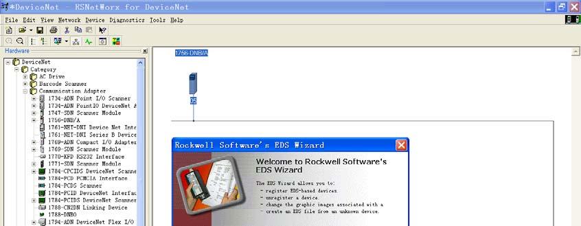
38 Input-Bytes: Number of DeviceNet input bytes Output-Bytes: Number of DeviceNet output bytes The parameters of input-bytes and output-bytes must be the same with the numbers of input/output bytes in DeviceNet master scanning list of SNetWorx and so on, or the connection can t be established. Mod_output_ctrl: Modbus output control Continuous Output Disable Output Output of Status Change: When the network output data has changed, Modbus commands can be sent. Note: If the output mode is Disable Output, though it has configured Modbus output commands, the gateway won t send Modbus output commands. To ensure securities of output-data, if PLC hasn t effective output-data (For example, PLC in programming mode or DeviceNet device has not been connected), Modbus output commands will not be sent. This parameter also could be modified through Modbus setting in GT DeviceNet network configuration instructions Users need install the *.EDS file in the disc to DeviceNet configuration software, then you can configure MD-210 through network configuration software. EDS(Electronic Data Sheet)is comprehensive description which supports DeviceNet network function. It equals to equipment s driver of Windows. Users need install EDS files to DeviceNet network configuration software, such as snetworx and so on, and then the configuration can be going on through network configuration software. Here we take ockwell's snetworx for example (edition ), and explain how to install. For further details, please refer to the network configuration software instructions. Step1: Create a new network configuration profile Step2: Select EDS operation guide, select Tools and then EDS-Wizard, you will see that:


39


40 Step3: Select NEXT, as follow: Step4: Install gateway MD-210 Shown as above, select egister an EDS file, as follow: Please register MD-210.EDS file we provided, according to the place where you save EDS file, and select the file. Step 5:Select the file registering to choose


41 Click NEXT : Step 6: Select the icon. Following network configuration software will prompt you the equipment category in equipment storehouse, you may choose icon in this process.

42 Here, the device has successfully registered to the icon library location of configuration software s equipment storehouse.

43 egistration location of gateway EDS Then, you should connect gateway MD-210 to DeviceNet network, click on SCAN button of snetworx, or select Network-Online in menu bar, your gateway will be scanned by system and identified exactly.
44 Appendix A: Modbus Protocol Modbus-TU Protocol: Note: The equipments being connected with this product must have Modbus interface, and Modbus protocol of the equipments must be in line with the following rules. Our company provides customer-oriented services. 1 Description of protocol Physical layer: transmission mode: S485 Address: Baud rate: Can configurate Medium: STP Transmission mode: Half-duplex mode The connection is established throng one line with half-duplex mode, and that is to say that signals transmit through the only one line with opposite directions. Firstly, host computer find the only terminal and then the terminal transmits response signals on the opposite direction. Protocol only allows the communication between host computers and terminals, while the communications between terminals are not allowed. Thus, they will not occupy communication line when they are in the status of being initialized and respond the polling signals which are transmitted to the local terminal only. Format of a data frame: 1 bit start bit, 8 bits data and 1 bit stop bit. Format of a data packet Address Function Code Data check code 8-Bits 8-Bits N x 8-Bits 16-Bits The protocol defines check code, data serial and so on in details, which are important contents when communicating specific data. When data frames reach terminal, they access to the equipment through a simple entrance. The equipment delete the envelop of the data frame, and read the data. If there are no faults, the required tasks are executed. Then, it adds the data being generated by itself to the obtained envelop, and return the data frame to the sender.
45 The response data include: the address of terminal, the executed function, and the required data and a check code by executing the order. Any faults won t lead to respond successfully. Address field Address field is located at the beginning, composed of 8 bits (0-255). These bits indicate the address of the terminal being specified by users. The equipment will receive data from the host computer being connected with it. Every address of terminal must be the only one. Only the terminal being addressed will respond the polling with its address. when the terminal transmit a response, the response tell the host computer the terminal which is communicating with it. Function field Codes of function field show the function being executed by terminals which are addressed. Table 1-1 lists all the function codes, their meanings and their initial functions. code meaning action Table1-1 Function codes 03 ead data obtain current binary value of single or multiple registers 06 Preset single register Place one specific binary value into the single register 16 Preset multiple Place specific binary values to a series of multiple registers registers Data field Data field includes data when specific functions are executed by terminals or data being collected when the terminal responds to query. The content of these data may be value of number, reference address or limit value. For instance, functional code indicates terminals read a register, data field, on the other hand, clearly show the register and the number of data to be read, the inside address, the type of data and different capacity of different computers. Fault check code The field allows checking the fault in the transmission between host computer and terminals. Sometimes, due to electrical noise and other interference, a set of data may change when transmitting from one equipment to another. The fault checking code can guarantee that host computer don t respond to the changed data in the transmission, which improves safety and efficiency of the system. The fault code apply 16 bit CC.
46 Note: The transmitting serial is always the same- address, functional code, data and the fault checking code relating to direction. The fault checking CC field occupy 2 bytes, including 16 bits binary value. The value of CC is calculated by transmitting equipment, and then added to the data frame, the receiving equipment calculate the CC value again while receiving data. Then it is compared with receiving CC value. If the two values are not the same, the fault occurs. When calculating CC, preset a 16-bit register to one firstly, and then calculate 8-bit bytes in the data frame with the current value of the register. Only 8 data bits of each byte participate in the generation of CC. The initial bit, final bit and occasional odd and even bit don t influence the value of CC. The process of generating a CC: Preset a 16-bit register to 0FFFFH, and the register is named CC register. When generating CC, exclusive each 8 bit with the content of the register, and then shift result to the low byte, the high bit is filled with zero, the LSB is shifted out and checked. If it is one, the register exclusives with a presetting fixed value. If the lowest bit is zero, there is no settlement. The above settlement is repeated before executing the shifting 8 times. After finishing shifting the last bit, the next 8-bit byte has the same exclusive calculation with the register, and the another 8-time shifting is carried out. When all the bytes are settled, the final value is CC value. The process of generating a CC: Preset a 16-bit register 0FFFFH (all one), and name it CC register. Exclusive the first 8-bit byte in the data frame with the low byte in the CC register, and restore CC register. Shift CC register to the right bit, fill the highest bit with zero, shift the lowest bit out and check them. If the lowest bit is zero, repeat the third step (next shift) If the lowest if one, exclusive CC register with a presetting fixed value (0A001H). epeat the third step and the fourth step until shifting eight times, which settle the entire eight bit down. epeat the second step to the fifth step to deal with the next eight-bit until all the bytes are settled down. In the end, CC register value is the CC value. 2 Functions of application layer The first chapter has described the protocol and data frame. The processors of the software can use the
47 following methods establish their specific application program via protocols without fault. The protocol in this chapter use the follow format as many as possible, the format is shown as table 2-1(digital is set in hexadecimal) Table 2-1 Address Functio The high byte The low The high The low The low The high nal code of the starting byte of the byte of the byte of the byte of byte of address of the starting number of number of checking checking variable address of the variable the variable code code the variable 03H 03H 00H 01H 00H 03H 55H E9H ead Holding egisters (Function code 03) Query The Table 2-2 is an example that reading there collected data U1, U2, and U3 to the slave. The address of U1 is 0001H, the address of U2 is 0002H, and the address of U3 is 0003H. Table 2-2 Address Functional The high byte The low byte The high byte The low The low The high code of the starting of the starting of the number byte of byte of byte of address of the address of the of the the checking checking variable variable variable number code code of the variable 03H 03H 00H 01H 00H 03H 55H E9H esponse The response include: the address of slave, functional code, the number of the data and the CC check. The example table 2-3 is reading the response of U1, U2, and U3.
48 Table 2-3 Address Functi The The The low The The low The The low The low The onal byte high byte of high byte of high byte of byte of high code number byte of the byte of the byte of the checkin byte of of the the variable the variable the variable g code checkin variable variable variable variable g code 03H 03H 06H 01H 7CH 01H 7DH 01H 7CH F9H 9BH 2.2 Preset Multiple egisters (Functional code 10) Query The functional code 10 allows users changing the content of multiple registers. The device can be set 16 values from any starting address. The controller work with the mode of dynamic scanning, and it can change the content of the register anytime. The Table 2-4 is an example changing the action and delay setting values of the monitor 1 and monitor 2 of the slave. The address of the action setting value of the monitor 1 is 2AH, and the delay setting value is 2BH. The address of the action setting value of the monitor 2 is 2CH, and the delay setting value is 2DH Table 2-4 Address Funct The The The The The The The The The The The The The The The ional high low high low byte high low high low high low high low low high code byte byte byte byte numb byte byte byte byte byte byte byte byte byte byte of the of the of the of the er of of the of the of the of the of the of the of the of the of of startin startin numb numb the variab variab variab variab variab variab variab variab checki checki g g er er variab le le le le le le le le ng ng addres addres of the of the le code code s of s of variab variab the the le le variab variab le le 节
49 03H 10H 00H 2AH 00H 04H 08H 07H D0H 00H 0AH 07H 0D0H 00H 0AH 25H 7CH esponse The Table 2-5 is the response of changing the action and delay setting values of the monitor 1 and monitor 2. Table 2-5 Address Function The high The low byte The high The low byte The low byte The high al code byte of the of the byte of the of the of checking byte of starting starting number number code checking address of address of of the of the code the variable the variable variable variable 03 10H 00H 2AH 00H 04H EBH 8DH 2.3 Preset Single egister (Functional code 06) Query The functional code 06 allows users changing the content of single register. Any single register of DAE system can use the order change the value. The controller work with the mode of dynamic scanning, and it can change the content of the register anytime. The following example is changing the overload-action value Ir1. The address of Ir1 is 002EH. Table 2-6 Addr Functio The high The low byte The high The low byte The low byte The high ess nal code byte of the of the byte of the of the of checking byte of starting starting variable variable code checking address of address of code the variable the variable 03H 06H 00H 2EH 07H 0D0H EBH 8DH esponse The normal response of preset single register is transmitting the receiving data after changing the value of the register.
50 Table 2-7 Addr Functio The high The low byte The high The low byte The low byte The high ess nal code byte of the of the byte of the of the of checking byte of starting starting variable variable code checking address of address of code the variable the variable 03H 06H 00H 2EH 07H 0D0H EBH 8DH
51 Appendix B: EDS document $ EZ-EDS Version 3.0 Generated Electronic Data Sheet $ DeviceNet Electronic Data Sheet $ Copyright (C) Shanghai Sibotech Automation Co. Ltd. [File] [Device] DescText = "Modbus-DeviceNet Gateway"; CreateDate = ; CreateTime = 08:57:44; ModDate = ; ModTime = 10:06:05; evision = 1.1; VendCode = 1016; VendName = "Shanghai Sibotech Automation Co. Ltd."; ProdType = 12; ProdTypeStr = "DC Drives"; ProdCode = 19; Majev = 1; Minev = 1; ProdName = "MD-210 Gateway"; Catalog = "MD-210"; [IO_Info] Default = 0x0001; PollInfo = 0x0001, 4, 4; Input1 = 8, 0, 0x0001, "un-time measurements and State", 6,
52 " ", "8 bytes"; Input2 = Input3 = Input4 = Input5 = Input6 = 16, 0, 0x0001, "Network Input 2", 6, " ", "16 Bytes"; 32, 0, 0x0001, "Network input 3", 6, " ", "32 Bytes"; 64, 0, 0x0001, "Network input 4", 6, " ", "64 Bytes"; 96, 0, 0x0001, "Network Input 5", 6, " ", "96 Bytes"; 128, 0,
53 0x0001, "Network Input 6", 6, " ", "128 Bytes"; Input7 = 160, 0, 0x0001, "Network Input 7", 6, " A 30 03", "Input 7 160bytes"; Output1 = 8, 0, 0x0001, "Network Output 1", 6, " ", "8 Bytes"; Output2 = 16, 0, 0x0001, "Network Output 2", 6, " ", "16 Bytes"; Output3 = 32, 0, 0x0001, "Network Output 3", 6, " ", "32 Bytes";
54 Output4 = 64, 0, 0x0001, "Network Output 4", 6, " ", "64 Bytes"; Output5 = 96, 0, 0x0001, "Network Output 5", 6, " ", "96 Bytes"; Output6 = 112, 0, 0x0001, "Network Output 6", 6, " ", "112 Bytes"; [ParamClass] MaxInst = 4; Descriptor = 0x0001; CfgAssembly = 0; [Params] Param1 = 0, 6,"20 A ", 0x0030, 8, 1, "Modbus_status", "",
55 "Status of Modbus, OK or The time out error Command No.", 0,50,0,,,,,,,,, 0; Param2 = 0, 6,"20 A ", 0x0012, 8, 1, "Input bytes", "", "Number of poll input connection bytes", 0,6,3,,,,,,,,, 0; Param3 = 0, 6,"20 A ", 0x0012, 8, 1, "Output bytes", "", "Number of poll output connection bytes", 0,5,3,,,,,,,,, 0; Param4 = 0, 6,"20 A ", 0x0002, 8, 1, "Mod_Output_Ctrl", "",
56 [EnumPar] Param2 = "8", "16", "32", "64", "96", "128", "160"; [Groups] Param3 = "8", "16", "32", "64", "96", "112"; "Control of Modbus Output Commands", 1,3,1,,,,,,,,, 0; Param4 = "Continous Output", "Disable Output", "Output of Status Change";
Modbus/ PROFIBUS DP Gateway PM-160
 Modbus/ PROFIBUS DP Gateway PM-160 REV 3.2 SiboTech Automation Co., Ltd. Technical Support: +86-21-5102 8348 E-mail: support@sibotech.net Table of Contents 1 About This Document... 3 1.1 General... 3 1.2
Table of Contents 1 ABOUT THIS DOCUMENT GENERAL COPYRIGHT INFORMATION TERMS ABOUT THE GATEWAY PRODUCT FUNCTIO
 DeviceNet/PROFIBUS-DP Adapter - User Manual REV 4.0 SiboTech Automation Co., Ltd. Technical Support: +86-21-5102 8348 E-mail:gt@sibotech.net Table of Contents 1 ABOUT THIS DOCUMENT...2 1.1 GENERAL... 2
Catalog 1 Product Overview General Important User Information About the Gateway Function Features Tec
 PROFIBUS DP / Modbus TCP Gateway EP-321MP User Manual REV 1.2 Sibotech Automation Co., Ltd Technical Support: 021-5102 8348 E-mail:support@sibotech.net Catalog 1 Product Overview... 4 1.1 General...4 1.2
Universal Serial/PROFIBUS DP Gateway GT200-DP-RS User Manual V6.1 SST Automation
 GT200-DP-RS V6.1 SST Automation E-mail: SUPPORT@SSTCOMM.COM WWW.SSTCOMM.COM Catalog 1 About the Gateway...4 1.1 Product Function...4 1.2 Product Features... 4 1.3 Technical Specifications... 4 1.4 Related
PROFIBUS DP/CAN Gateway PCA-100. User Manual
 PCA-100 REV 4.0 SiboTech Automation Co., Ltd. Technical Support: 021-5102 8348 E-mail: support@sibotech.net Catalog 1 Introduction... 2 1.1 About This Instruction... 2 1.2 Copyright... 2 1.3 Related Products...
HART/ MODBUS Gateway HTM-611. User Manual REV
 HAT/ MODBUS Gateway HTM611 EV 1.6 SiboTech Automation Co., Ltd. Technical Support: +86215102 8348 Email: support@sibotech.net HAT/ Catalog 1 Product Overview... 4 1.1 Product Function... 4 1.2 Product
HART / EtherNet/IP Gateway GT200-HT-EI User Manual V 1.0 REV A SST Automation
 HART / EtherNet/IP Gateway GT200-HT-EI V 1.0 REV A SST Automation E-mail: SUPPORT@SSTCOMM.COM WWW.SSTCOMM.COM Catalog 1 Product Overview... 4 1.1 Product Function...4 1.2 Product Features... 4 1.3 Technical
HART/ Modbus TCP Gateway GT200-HT-MT User Manual V 1.2 REV A SST Automation
 HART/ Modbus TCP Gateway GT200-HT-MT User Manual V 1.2 REV A SST Automation E-mail: SUPPORT@SSTCOMM.COM WWW.SSTCOMM.COM Catalog 1 Product Overview... 4 1.1 Product Function...4 1.2 Product Features...
SST Automation
 EtherNet / CAN Gateway GT200-MT-CA REV 1.0 SST Automation E-mail: SUPPORT@SSTCOMM.COM WWW.SSTCOMM.COM Catalog 1 About This Document... 4 1.1 General...4 1.2 Important Information... 4 1.3 Related Products...
Embedded Modbus TCP Module GS11-MT. User Manual REV 1.1. SST Automation.
 Embedded Modbus TCP Module GS11-MT User Manual REV 1.1 SST Automation E-mail: SUPPORT@SSTCOMM.COM WWW.SSTCOMM.COM Catalog 1 About the Embedded Module... 4 1.1 General...4 1.2 Features... 4 1.3 Specifications...4
MAC VALVES, INC. A ENGINEERING RELEASE TRJ B EDS UPDATE / NAME CHANGE BI 284 TJR/KD. User s Manual for MAC Valves DeviceNet
 MAC VALVES, INC. DOCUMENT NUMBER TITLE: User s Manual for MAC Valves DeviceNet PAGE 1 OF 24 UI-20 SM16 Manifold REVISION LEVEL DATE RELEASED CHANGE ECN NUMBER P.E. APPROVAL P.D. APPROVAL A 7-21-99 ENGINEERING
MRUC-20 Modul-R CAN Bus Network
 MRUC-20 Modul-R CAN Bus Network BALOGH This manual is based on information available at the time if its publication. Every effort has been made to provide accurate and up-to-date information. This document
GW-7228 J1939/Modbus RTU Slave Gateway
 GW-7228 J1939/Modbus RTU Slave Gateway User s Manual www.icpdas.com GW-7228 J1939/Modbus RTU Slave Gateway User s Manual (Ver 1.2, May/2011) ------------- 1 Warranty All products manufactured by ICP DAS
GE FANUC Parts 1. DeviceNet Network Master/Slave August 2002 GFK-1539A. Quick Start Guide. Product Description. Specifications. Preinstallation Check
 Product Description Revision Letter: BA Firmware version: 1.10 Firmware upgrades: DeviceNet Certification: Product Name: None Certificate available upon request. DeviceNet Network Control Module (NCM)
Model IR4000M. Multi-Point Monitor Modbus programming guide
 Model I4000M Multi-Point Monitor Modbus programming guide The information and technical data disclosed in this document may be used and disseminated only for the purposes and to the extent specifically
Motortronics VirtualSCADA VS2-MT Communication Gateway VS2-MT User Manual Revision
 Motortronics VirtualSCADA VS2-MT Communication Gateway VS2-MT User Manual Revision 1.03.00 Motortronics / Phasetronics 1600 Sunshine Drive Clearwater, Florida 33765 Tel: 727-573-1819 Fax: 727-573-1803
INTELLIS. Modbus Direct Network Monitor
 INTELLIS Modbus Direct Network Monitor System Installation and Operation Manual Phone: (201) 794-7650 Fax: (201)794-0913 Chapter 1 Modbus Protocol Revision History Revision 1.0 30 April, 2002 Initial Version
Gateway 1400 Reference Manual
 Profibus-DP Gateway 1400 Reference Manual Copyright All Rights Reserved. No part of this document may be copied, reproduced, republished, uploaded, posted, transmitted, distributed, stored in or introduced
USER MANUAL FOR FIOA-0402-U-16
 USER MANUAL FOR FIOA-0402-U-16 COPYRIGHT NOTICE This manual is a publication of Renu Electronics Pvt. Ltd. and is provided for use by its customers only. The contents of the manual are copyrighted by Renu
INSTRUCTION SHEET. Eaton Logic Controller DeviceNet Distributed I/O Adapter Module. [Applicable Distributed I/O Adapter Module] ELC-CADNET
![INSTRUCTION SHEET. Eaton Logic Controller DeviceNet Distributed I/O Adapter Module. [Applicable Distributed I/O Adapter Module] ELC-CADNET](/thumbs/88/117222526.jpg "INSTRUCTION SHEET. Eaton Logic Controller DeviceNet Distributed I/O Adapter Module. [Applicable Distributed I/O Adapter Module] ELC-CADNET") 2010-12-10 5011697801-ECD1 Eaton Logic Controller DeviceNet Distributed I/O Adapter INSTRUCTION SHEET [Applicable Distributed I/O Adapter ] IL05004007E 002-1214120-02 Thank you for choosing the Eaton Logic
2010-12-10 5011697801-ECD1 Eaton Logic Controller DeviceNet Distributed I/O Adapter INSTRUCTION SHEET [Applicable Distributed I/O Adapter ] IL05004007E 002-1214120-02 Thank you for choosing the Eaton Logic
Tongta Inverter TDS-F8
 Tongta Inverter TDS-F8 MODBUS Communication Application Manual Please ensure the user gets this manual, for the optimal use of this device. 1. Introduction: TEK-DRIVE / TDS-F8 INVERTER MODBUS Communication
Modbus communication module for TCX2: AEX-MOD
 Modbus communication module for TCX2: Communication Specification Features S485 2-wire MODBUS standard in accordance with EIA/TIA 485. Slave type of communication Supports up to 127 nodes on one network
Product Specification for SAB-S-MODBUS
 SAB-S-MODBUS May 9, 2011 Product Specification for SAB-S-MODBUS The SAB-S-MODBUS is a two-channel module that measures single or multiple magnet transducer position and returns this information to a host
Description of options. user s manual. DEIF A/S Frisenborgvej 33 DK-7800 Skive Tel.: Fax:
 Description of options TCP/IP Ethernet module user s manual DEIF A/S Frisenborgvej 33 DK-7800 Skive Tel.: +45 9614 9614 Fax: +45 9614 9615 info@deif.com www.deif.com Document no.: 4189320029B Legal information
Model 3000 Fieldbus Transmitter
 Model 3000 Fieldbus Transmitter (for load cell based weighing systems) Installation & Operating Manual (Software Code PDT409 / Release 0.0) Modbus RTU / Profibus DP / DeviceNet Versions P.O. Box 775 -
Intech Micro 2300-A8VI analogue input station MODBUS RTU slave application supplementary manual.
 Intech Micro 2300-A8VI analogue input station MODBUS RTU slave application supplementary manual. MODBUS supplementary manual to the 2300-A8VI Installation Guide. The 2300 series stations are designed to
How-To. Modbus-TCP communication between CelciuX and NJ. History
 History Date Version Author Description 03.10.12 1.0 pk 1 st release 04.10.12 1.1 pk Added very important notes (tips and tricks) 22.11.12 1.2 pk Minor corrections according Thomas Grootenboers HowTo_ModbusTCP_CelciuX_NJ.docx
MPCR Series DeviceNet Technical Manual TDMPCRDNTM2-0EN 01/08 Subject to change without notice
 MPCR Series DeviceNet Technical Manual Table of Contents MPCR Series Introduction... 3 Product Overview... 3 About DeviceNet... 4 Overview... 4 MPCR DeviceNet Features... 4 Cabling and Drop Line Lengths
isma-b-mg-ip User Manual Global Control 5 Sp. z o.o. Poland, Warsaw
 isma-b-mg-ip User Manual Global Control 5 Sp. z o.o. Poland, Warsaw www.gc5.pl Table of content 1 Introduction... 4 1.1 Revision history... 5 1.2 Safety rules... 5 1.3 Technical specifications... 6 1.4
2. Terminal arrangement TEMPERATURE CONTROLLER KT2 COMMUNICATION INSTRUCTION MANUAL. (Fig. 2-1)
") COMMUNICATION INSTRUCTION MANUAL TEMPERATURE CONTROLLER No.KTC3E2 2006.08 To prevent accidents arising from the misuse of this controller, please ensure the operator receives this manual. For this product
COMMUNICATION INSTRUCTION MANUAL TEMPERATURE CONTROLLER No.KTC3E2 2006.08 To prevent accidents arising from the misuse of this controller, please ensure the operator receives this manual. For this product
GW-7238D J1939 to Modbus TCP Server / RTU Slave Gateway
 GW-7238D J1939 to Modbus TCP Server / RTU Slave Gateway User s Manual www.icpdas.com 1 Warranty All products manufactured by ICP DAS are under warranty regarding defective materials for a period of one
WRC Modbus to DeviceNet Gateway for GPD 506/P5
 Introduction This document describes the recommended method to configure and connect Western Reserve Controls (WRC) Modbus to DeviceNet gateway for use with the GPD 506/P5. There currently are three types
TABLE OF CONTENTS. Communication Functions
 TABLE OF CONTENTS Chapter 1: Chapter 2: Chapter 3: Chapter 4: General Features....................................................... 1-1 Functions......................................................
It is the installer's responsibility to follow all instructions in this manual and to follow correct electrical practice.
 MCD Modbus Module Instructions Important User Information INSTALLATION INSTRUCTIONS: MCD MODBUS MODULE Order Code: 175G9000 1. Important User Information Observe all necessary safety precautions when controlling
SDM-8AO. Expansion Module 8 analog outputs. Manufactured for
 Version 1.0 16.05.2014 Manufactured for Thank you for choosing our product. This manual will help you with proper support and proper operation of the device. The information contained in this manual have
Du line. Dupline Field- and Installationbus Dupline Ethernet Modbus/TCP Gateway Type G G Type Selection
 Dupline Field- and Installationbus Dupline Ethernet Modbus/TCP Gateway Type G 3891 0052 Built-in Dupline channel generator Modbus/TCP Slave 10 and 100 Mbit operation, full or half duplex Twisted pair cables
Product Specification for CANbus to DeviceNet Transducer Gateway
 XG CANbus to DeviceNet Transducer Gateway April, 00 Product Specification for CANbus to DeviceNet Transducer Gateway The XG CANbus to DeviceNet Temposonics Gateway gathers position information from as
Fox Thermal Instruments, Inc.
 Fox Thermal Instruments, Inc. THERMAL MASS FLOW METER & TEMPERATURE TRANSMITTER Model FT2A - Anybus: Profibus/DeviceNet/Modbus TCP Ethernet www.foxthermalinstruments.com 399 Reservation Road Marina, CA.
Interface WM : PD
 ふ Interface WM : PD4000301 This is a hazard alert mark. This mark informs you about the operation of the product. Note This manual is subject to change without notice at any time to improve the product.
Ethernet/SIOX Gateway Applicable to firmware ver 1.0
 ES2 Ethernet/SIOX Gateway p 2 TELEFRANG AB TABLE OF CONTENTS Ethernet/SIOX Gateway Applicable to firmware ver 1.0 General Description The ES2 module is a Gateway between a LAN/WAN Ethernet network and
SDM-6RO. Expansion Module 6 relay outputs. Manufactured for
 Version 1.0 5.02.2014 Manufactured for Thank you for choosing our product. This manual will help you with proper support and proper operation of the device. The information contained in this manual have
Fieldbus Appendix AnyBus-S FIPIO
 Fieldbus Appendix AnyBus-S FIPIO DOC.ID: ABS-FIP-1 Rev. 1.00 HMS Industrial Networks Germany Japan Sweden U.S.A + 49-721 - 96472-0 + 81-45 - 478-5340 + 46-35 - 17 29 20 + 1-773 - 404-2271 sales-ge@hms-networks.com
The accessories described in this manual are of the highest quality, carefully designed and built in order to ensure excellent performance.
 INTRODUCTION Thank you for choosing our product. The accessories described in this manual are of the highest quality, carefully designed and built in order to ensure excellent performance. This manual
PM290 POWERMETER. Communication Protocols ASCII & Modbus Reference Guide
 PM290 POWERMETER Communication Protocols ASCII & Modbus Reference Guide PM290 Communication Protocols Communication protocol is a method of transferring information between different devices (i.e., the
tsh-700 Series User Manual
 tsh-700 Series User Manual Tiny Serial Port Sharer Aug. 2017 Ver. 1.6 WARRANTY All products manufactured by ICP DAS are warranted against defective materials for a period of one year from the date of delivery
PLC2 Board Communication Manual CANopen Slave
 PLC2 Board Communication Manual CANopen Slave 02/2006 Series: PLC2 0899.5809 E/3 Contents Contents List of Tables 4 List of Figures 4 About the Manual 5 Abbreviations and Definitions...............................
EQ-DCM User Manual Revision 1.02 Sep 10, 2013
 EQ-DCM User Manual www.equustek.com Revision 1.02 Sep 10, 2013 Contents INTRODUCTION...5 ABOUT THIS MANUAL... 5 INTENDED AUDIENCE... 5 HARDWARE SPECIFICATIONS...6 PHYSICAL SPECIFICATIONS... 6 HARDWARE
ECAN-240. (Modbus TCP to 2-port CAN Bus Gateway User manual) ECAN-240 Modbus TCP to 2-port CAN Bus Gateway User Manual, Version 1.0.
 ECAN-240 Modbus TCP to 2-port CAN Bus Gateway User Manual, Version 1.0.") ECAN-240 (Modbus TCP to 2-port CAN Bus Gateway User manual) ECAN-240 Modbus TCP to 2-port CAN Bus Gateway User Manual, Version 1.0.0 Page: 1 Table of Contents Table of Contents -----------------------------------------------------------------------------2
ECAN-240 (Modbus TCP to 2-port CAN Bus Gateway User manual) ECAN-240 Modbus TCP to 2-port CAN Bus Gateway User Manual, Version 1.0.0 Page: 1 Table of Contents Table of Contents -----------------------------------------------------------------------------2
Anybus-S CC-Link. Fieldbus Appendix. Rev HMS Industrial Networks AB. Germany Japan Sweden U.S.A UK
 Fieldbus Appendix Anybus-S CC-Link Rev. 1.51 HMS Industrial Networks AB Germany Japan Sweden U.S.A UK +49-721 - 96472-0 +81-45 - 478-5340 +46-35 - 17 29 20 +1-773 - 404-3486 +44-1908 - 359301 sales-ge@hms-networks.com
MPCR Series DeviceNet Technical Manual
 MPCR Series DeviceNet Technical Manual Table of Contents MPCR Series Introduction...3 Product Overview...3 About DeviceNet...4 Overview...4 MPCR DeviceNet Features...4 Cabling and Drop Line Lengths (as
HRM-0800 Instruction Manual
 HRM-0800 Instruction Manual Table of Contents 1 Highway Addressable Remote Transducer (HART ) 4 2 General Specifications 5 3 Dimensions: 6 4 General Description 7 4.1 Introduction 7 4.2 Purpose 8 4.3 Functions
RS485 MODBUS Module 8AO
 Version 1.3 12/02/2013 Manufactured for Thank you for choosing our product. This manual will help you with proper support and proper operation of the device. The information contained in this manual have
J1939/Modbus Slave Gateway FAQ
 J1939/Modbus Slave Gateway FAQ Version 1.0 (For GW-7228/GW-7238D) ICP DAS Co., Ltd. Table of Contents J1939/Modbus Slave Gateway FAQ v1.0 Q01 : How to solve CAN Bus Transmission Fail problem?... 2 Q02
RTU560 Connections and Settings DIN Rail RTU 560CIG10
 Connections and Settings DIN Rail RTU 560CIG10 Application, characteristics and technical data have to be taken from the hardware data sheet: 560CIG10 1KGT 150 719 Operation The 560CIG10 is a DIN rail
RTD Temperature acquisition converter WJ25
 8-CH Thermocouple Signal to RS485/232 Acquisition Converter (WJ27 series 24Bits A/D Converter, data acquisition) Features: >> Eight channels thermocouple signal acquisition, isolated converter RS-485/232
ELC-CODNETM. Effective December Users Manual
 Effective December Users Manual Introduction This is an OPEN-TYPE device and therefore should be installed in an enclosure free of airborne dust, excessive humidity, shock and vibration. The enclosure
Configuration for General DIP Devices. Setting Up RSLinx
 Configuration for General DIP Devices Setting Up RSLinx Start Up RSLinx Program. Go to Communications Configure Drivers. Then, select an Available Driver Type (example, DeviceNet drivers). Once the appropriate
Operation manual. HDOM-Profibus-V0. More options please visit;www.veikong-electric.com
 Operation manual HDOM-Profibus-V0 More options please visit;www.veikong-electric.com Contents 1 Introduction... 1 1.1 Product description... 1 1.2 HDOM-Profibus-V0 label... 1 1.3 Technical specifications...
JSD81 series products are based on SCM's intelligent monitoring and control system, users set the calibration value,
 8-Channel Analog Signals to RS485/232 Converter(A/D Converter JSD81 series) Features: 8-CH analog signal acquisition/isolation,rs-485/232 output 24-bit AD converter, testing accuracy>0.05% Can Program
VPGate Manual PROFIBUS to serial
 VPGate Manual PROFIBUS to serial Important information Purpose of the Manual This user manual provides information how to work with the VPGate PROFIBUS to serial. Document Updates You can obtain constantly
EGW1-IA3-MB User s Manual
 www.exemys.com Rev. 0 1 Products are in constant evolution to satisfy our customer needs. For that reason, the specifications and capabilities are subject to change without prior notice. Updated information
1. Introduction. 2. Installation MODBUS INTERFACE
 5551.C 8473.C MODBUS INTERFACE PIM-MB-1 Modbus Interface 1. Introduction AuCom soft starters can be controlled and monitored across an RS485 serial communication network using the Modbus RTU and AP ASCII
Intech Micro 2300-RTD6 analogue input station MODBUS RTU slave application supplementary manual.
 Intech Micro 2300-RTD6 analogue input station MODBUS RTU slave application supplementary manual. MODBUS supplementary manual to the 2300-RTD6 Installation Guide. The 2300 series stations are designed to
BridgeWay. PROFIBUS to DeviceNet Gateway User Manual. Part No. AB7605. Publication PUB-AB
 BridgeWay PROFIBUS to DeviceNet Gateway User Manual Part No. AB7605 Pyramid Solutions 1850 Research Drive, Suite 300 Troy, Michigan 48083 Phone 248-524-3890 Web www.pyramid-solutions.com Publication PUB-AB7605-005
12.3 Fieldbus I/O Board
 12.3 Fieldbus I/O Board 12.3.1 Overview of Fieldbus I/O The Fieldbus I/O option is an option to add fieldbus slave function (DeviceNet, PROFIBUS-DP, CC-Link, EtherNet/IP) to the robot Controller. A fieldbus
CVIC II - CVIL II - CVIR II - MULTICVIL II - Memory Mapping - Manual
 1/36 CVIC II - CVIL II - CVIR II - MULTICVIL II - Memory Mapping - Manual N - Copyright 2011, St Herblain France All rights reserved. Any unauthorized use or copying of the contents or part thereof is
Intech Micro 2300-RO4 analogue input station MODBUS RTU slave application supplementary manual.
 Intech Micro 2300-RO4 analogue input station MODBUS RTU slave application supplementary manual. MODBUS supplementary manual to the 2300-RO4 Installation Guide. The 2300 series stations are designed to
iopro Mirrored IO System
 Ph: (877) 343-8467 Fax: (800) 303-5381 Email: info@ioselect.com iopro Mirrored IO System Quick Start Guide (Ver. 6) www.ioselect.com Page 1 Introduction This document will cover how to use the iopro family
D8000 SERIES QUICK START GUIDE
 D8000 SERIES QUICK START GUIDE Version 1.0 Overview The D8000 series modules require a DC Voltage power supply, a USB cable and an unused computer USB port for proper operation. Connecting the D8000 series
Document Name: User Manual for SC10MK, Modbus RTU to Modbus TCP Converter
 Document Name: User Manual for SC10MK, Modbus RTU to Modbus TCP Converter Login for the first time, please use http://192.168.1.100 To key in user name and password is for identifying authorization. Default
INSTRUCTION MANUAL WCS-Interface Module, DeviceNet
 FACTORY AUTOMATION INSTRUCTION MANUAL WCS-Interface Module, DeviceNet WCS-DG210 Part. No. 202340 / DOCT-1305 / 11. june 2007 1 Working principle............................ 6 2 Installation and commissioning.................
X-gateway Interface Addendum DeviceNet Scanner Interface
 X-gateway Interface Addendum DeviceNet Scanner Interface Rev. 1.10 HMS Industrial Networks AB Germany Japan Sweden U.S.A + 49-721 - 96472-0 + 81-45 - 478-5340 + 46-35 - 17 29 20 + 1-773 - 404-3486 ge-sales@hms-networks.com
User Guide. Modbus Module. For Digistart soft starters. Part Number: Issue: 3.
 User Guide Modbus Module For Digistart soft starters Part Number: 477-9-3 Issue: 3 General Information The manufacturer accepts no liability for any consequences resulting from inappropriate, negligent
MODEL: R3-NE1. Remote I/O R3 Series. ETHERNET INTERFACE MODULE (Modbus/TCP) 27.5 (1.08)
 27.5 (1.08)") MODEL: R-NE Remote I/O R Series ETHERNET INTERFACE MODULE (Modbus/TCP) 7. (.8) 9 (.9) (.) mm (inch) MODEL: R-NE-[][] ORDERING INFORMATION Code number: R-NE-[][] Specify a code from below for each [] and
MODEL: R-NE Remote I/O R Series ETHERNET INTERFACE MODULE (Modbus/TCP) 7. (.8) 9 (.9) (.) mm (inch) MODEL: R-NE-[][] ORDERING INFORMATION Code number: R-NE-[][] Specify a code from below for each [] and
LVX Control Unit. Features:
 Date 2013-02-28 Control Unit Features: Most parameters can be defined as required for your interfaces. You decide which information is output and how. Fast cycle times, just a few µs/beam. Maximum beam-count
VersaMax* DeviceNet Network Master/Slave
 Product Description Quick Start Guide Revision: Firmware version: 1.10 Firmware upgrades: Specifications Operating Modes: Slaves Supported: Configuration: IC200BEM103-MA None Master only, Slave only, Combined
THERMO-CON. Model No. HECR002-A5. Keep available whenever necessary.
 HEC-OM-S008 Aug.2014 Communication Manual THERMO-CON Model No. HECR002-A5 Keep available whenever necessary. This manual is copyrighted and all rights are reserved by SMC Corporation, and may not, in whole
USER S MANUAL. PH485Ex1. #1 RS-485 Serial Port to Ethernet, Terminal Server/Client. Doc No: PH485Ex1-UM-001 IPEX. (IP Electronix)
") USER S MANUAL PH485Ex1 Doc No: PH485Ex1-UM-001 #1 RS-485 Serial Port to Ethernet, Terminal Server/Client IPEX (IP Electronix) Contents 1. INTRODUCTION... 3 2. SPECIFICATIONS... 3 3. PACKAGE CHECKLIST...
USER S MANUAL PH485Ex1 Doc No: PH485Ex1-UM-001 #1 RS-485 Serial Port to Ethernet, Terminal Server/Client IPEX (IP Electronix) Contents 1. INTRODUCTION... 3 2. SPECIFICATIONS... 3 3. PACKAGE CHECKLIST...
Contents. Introduction 1. 1 Overview communication interface Communication protocol 2. 2 Communication specifications 2
 Contents Introduction 1 1 Overview 2 1.1 485 communication interface 2 1.2 Communication procol 2 2 Communication specifications 2 3 Confirmation and setting method of communication specification 3 4 Connection
SDM-8I8O. Expansion Module 8 digital inputs, 8 digital outputs. Manufactured for
 Version 1.2 20.01.2014 Manufactured for Thank you for choosing our product. This manual will help you with proper support and proper operation of the device. The information contained in this manual have
G5 Weighing Instrument
 G5 Weighing Instrument Program version 1.4.X Fieldbus Option Manual PM and RM types CONTENTS 1. Introduction... 1-1 General... 1-1 Module installation... 1-2 Ordering information... 1-3 2. Modules...
This manual may not be reproduced in whole or in part by any means, without written permission of Accuenergy.
 Copyright 2008 V1.10 This manual may not be reproduced in whole or in part by any means, without written permission of Accuenergy. The information contained in this document is believed to be accurate
GE MDS, LLC. NETio Series. Protocol Communications Supplement. March 2013 Part No A01, Rev. C
 GE MDS, LLC. NETio Series Protocol Communications Supplement March 2013 Part No. 05-4672A01, Rev. C Modbus Protocol NETio Architectural Implementation As described in detail below, the Modbus RTU protocol
E2 Modbus RTU Register Map Revision History Version Comments Author Date 1.02 Previous version PAE 11/06/ Revised to new format PAE 09/03/09
 Application Note Title AN-ODE-01 E2 Modbus RTU Register Map Revision History Version Comments Author Date 1.02 Previous version PAE 11/06/08 1.03 Revised to new format PAE 09/03/09 General This document
1. Overview Technical Specifications Applications Pin Description Connection Diagram of RS 485 / 422 Converter...
 CONTENTS 1. Overview...3 2. Technical Specifications........4 3. Applications........5 4. Pin Description..... 5 5. Connection Diagram of RS 485 / 422 Converter..........6 6. Troubleshooting....7 7. Frequently
GW-7472 / GW EtherNet/IP to Modbus RTU/TCP Gateway User Manual
 GW-7472 / GW-7473 EtherNet/IP to Modbus RTU/TCP Gateway User Manual Warranty All products manufactured by ICP DAS are under warranty regarding defective materials for a period of one year, starting from
The I-7530A-MR Modbus RTU to CAN Converter
 The I-7530A-MR Modbus RTU to CAN Converter User s Manual Warranty All products manufactured by ICP DAS are under warranty regarding defective materials for a period of one year from the date of delivery
The I-7530A RS-232/485/422 to CAN Converter
 The I-7530A RS-232/485/422 to CAN Converter User s Manual Warranty All products manufactured by ICP DAS are under warranty regarding defective materials for a period of one year from the date of delivery
Flex Series User Guide
 User Programmable Current 4..20mA Digital RS485 Dual & Single Axis Up to 360º 2016 Flex Series User Guide Sensor Installation, Wiring, Flexware App Instructions Page 1 of 33 Page 2 of 33 Table of Contents
EQ7000. User Manual. Rev 1.00
 EQ7000 User Manual Rev 1.00 www.equustek.com Revision 1.00 February 27, 2009 Contents INTRODUCTION...4 ABOUT THIS MANUAL...4 INTENDED AUDIENCE...4 HARDWARE SPECIFICATIONS...5 PHYSICAL SPECIFICATIONS...5
WSK INTELLIGENT TEMPERATURE AND HUMIDITY CONTROLLER USER MANUAL
 WSK INTELLIGENT TEMPERATURE AND HUMIDITY CONTROLLER USER MANUAL WSK INTELLIGENT TEMPERATURE AND HUMIDITY CONTROLLER USER MANUAL v 1.0 Thanks for choosing the Intelligent temperature and humidity controller
INDEX. Document Name : User Manual for SC10EJ Serial to Ethernet Converter
 Document Name : User Manual for SC10EJ Serial to Ethernet Converter Page 1 of 10 INDEX 1. Technical Specifications 1 2. Modes of Operation 1 3. Configuring the SC10 EJ : Through Serial Port 2 a. Configuring
CONFIGURATION GUIDE A-B REMOTE I/O LINK ADAPTOR FOR DL-KFR PC CARDS
 CONFIGURATION GUIDE A-B REMOTE I/O LINK ADAPTOR FOR DL-KFR PC CARDS This configuration guide provides programming information for the DL-PC (ISA) and DL-STD (STD 80 and 32) Remote I/O Link applications.
ABSOLUTE ROTARY ENCODER WITH DEVICENET INTERFACE USER MANUAL
 ABSOLUTE ROTARY ENCODER WITH DEVICENET INTERFACE USER MANUAL 1. Introduction... 4 1.1 Control and Information Protocol (CIP)... 5 1.2 Object modell... 6 2. Data Transmission... 7 2.1. The Object Dictionary...
I-7530 Series FAQ. ICP DAS Co., LTD 1
 I-7530 Series FAQ Q1 How do I configure the I-7530, such as baud, Acceptance Code, Acceptance Mask and so forth? (2011/1/5,Bear)... 3 Q2 How does these two parameter, Acceptance Code and Acceptance Mask,
MLC 9000 Profibus and DeviceNet Gateway User Guide
 MLC 9000 Profibus and DeviceNet Gateway Revision 2.02 ISE, Inc. - 10100 Royalton Rd. - Cleveland, OH USA - tel: (440) 237-3200 - fax: (440) 237-1744 - http://instserv.com Contents 1. TECHNICAL OVERVIEW...2
Motors I Automation I Energy I Transmission & Distribution I Coatings. SymbiNet CFW-11. User s Manual
 Motors I Automation I Energy I Transmission & Distribution I Coatings SymbiNet CFW-11 User s Manual SymbiNet User s Manual Series: CFW-11 Language: English Document Number: 10002033446 / 00 Publication
1782-JDC DeviceNet/Serial Gateway User s Manual
 1782-JDC DeviceNet/Serial Gateway User s Manual Western Reserve Controls, Inc. Although every effort has been made to insure the accuracy of this document, all information is subject to change without
How to Control and Monitor a C441 Motor Insight via DeviceNet
 Application of DeviceNet and Motor Insight How to Control and Monitor a C441 Motor Insight via DeviceNet Application: The purpose of this application example is to demonstrate how to control and monitor
Signal Isolators & Conditioners
 WJ21 series Analog Signal to RS485/232 Converter (A/D Converter) Features: >> Analog signal acquisition, isolated RS-485/232 output >> 12-bit AD converter, testing accuracy>0.1% >> Can Program and calibrate