Introduction to diffraction and the Rietveld method
|
|
|
- Amice Polly Jackson
- 5 years ago
- Views:
Transcription


1 Introduction to diffraction and the Rietveld method Luca Lutterotti Department of Materials Engineering and Industrial Technologies, University of Trento - Italy Luca.Lutterotti@unitn.it
2 Goal of the Rietveld method To minimize the residual function using a non-linear least squares algorithm 2 1 WSS = w i ( Iiexp Iicalc ),w i = i Iiexp and thus refine the crystal structure of a compound (cell parameters, atomic positions and Debye-Waller factors) 500 Intensity1/2 [a.u.] θ [degrees]
3 Bragg law Constructive interference and interplanar spacing:
4 Reciprocal space d hkl = V C s 11 h 2 + s 22 k 2 + s 33 l 2 + 2s 12 hk + 2s 13 hl + 2s 23 kl
5 Bragg law and intensities Considering the diffraction from the (001) plane!"#!$#!"#!$# %&'()*'+"()',*-.()'$*(/**-'0"12'3' "-4'5'46&&*02'$1'λ7'()*'+"()',*-.()' $*(/**-'0"12'3'"-4'8'/6,,'46&&*0'$1' λ95'"-4'4*2(0:;(6<*'6-(*0&*0*-;*'6-'!$#'/6,,',*"4'(='-='46&&0";(*4' 6-(*-26(1
6 A typical diffraction pattern
7 Diffraction intensities The intensity in a powder diffractometer I i calc = S F Nphases j=1 f j V j 2 Npeaks k=1 L k F k, j 2 S ( j 2θ i 2θ k, j )P k, j A j + bkg i The structure factor: F k, j 2 = mk N n=1 f n e B n sin 2 θ λ 2 ( e 2πi ( hx n +ky n +lz n )) 2
8 Counts X10E Counts X10E X-ray and neutron diffraction X-ray Diffraction - CuKa Phillips PW1710 Higher resolution Intensity falloff at small d spacings Better at resolving small lattice distortions CPD RRRR PbSO4 Cu Ka X-ray data Scan no. = 1 Lambda1,lambda2 = Observed Profile CPD RRRR PbSO A neutron data 8.8 Scan no. = 1 Lambda = Observed Profile D-spacing, A D-spacing, A Neutron Diffraction - D1a, ILL!=1.909 Å Lower resolution Much higher intensity at small d-spacings Better atomic positions/thermal parameters
9 Diffraction analyses Phase identifications (crystalline and amorphous) Crystal structure determination Crystal structure refinements Quantitative phase analysis (and crystallinity determination) Microstructural analyses (crystallite sizes - microstrain) Texture analysis Residual stress analysis Order-disorder transitions and compositional analyses Thin films
10 The Rietveld method Need to refine crystal structures from powder. Peaks too much overlapped: Groups of overlapping peaks introduced. Not sufficient. Peak separation by least squares fitting (gaussian profiles). Not for severe overlapping First refinement program by H. M. Rietveld, single reflections + overlapped, no other parameters than the atomic parameters. Rietveld, Acta Cryst. 22, 151, First complete program with structures and profile parameters. Distributed 27 copies (ALGOL) Fortran version. Distributed worldwide Wide acceptance. Extended to X-ray data. Today: the Rietveld method is widely used for different kind of analyses, not only structural refinements. If the fit of the assumed model is not adequate, the precision and accuracy of the parameters cannot be validly assessed by statistical methods. Prince.
11 Goal of the Rietveld method 500 To minimize the residual function: i where: I calc 2 i ),w i = 1 Iiexp Intensity1/2 [a.u.] WSS = w i ( I exp i calc Ii = SF Lk Fk S (2θ i 2θ k ) Pk A + bkgi -100 k Pk = preferred orientation function S (2θ i 2θ k ) = profile shape function (PV : η,hwhm) HWHM 2 = U tan 2 θ + V tan θ + W 3 / sin α Pk = r cos 2 α + r using a non-linear least squares algorithm θ [degrees]
12 The classical Rietveld method The function to minimize by a least squares method (non linear): the spectrum is calculated by the classical intensity equation: Nphases Npeaks f I calc i = S j 2 F L 2 k F k, j S j ( 2θ i 2θ k, j )P k, j A j + bkg i V j j=1 k=1 The spectrum depends on WSS = w i I exp calc ( i I ) 2 i,w i = 1 i phases: crystal structure, microstructure, quantity, cell volume, texture, stress, chemistry etc. instrument geometry characteristics: beam intensity, Lorentz- Polarization, background, resolution, aberrations, radiation etc. sample: position, shape and dimensions, orientation. Each of the quantity can be written in term of parameters that can be refined (optimized). I i exp
 Line broadening (determines the shape of the peaks) Number and positions of")
13 The classical Rietveld method I i calc = S F Nphases j=1 f j V j 2 Npeaks k=1 L k F k, j 2 S ( j 2θ i 2θ k, j )P k, j A j + bkg i The spectrum (at a 2θ point i) is determined by: a background value some reflection peaks that can be described by different terms: Diffraction intensity (determines the height of the peaks) Line broadening (determines the shape of the peaks) Number and positions of the peaks
14 The classical Rietveld method I i calc = S F Nphases j=1 f j V j 2 Npeaks k=1 L k F k, j 2 S ( j 2θ i 2θ k, j )P k, j A j + bkg i The more used background in Rietveld refinements is a polynomial function in 2θ : bkg 2θ i N b is the polynomial degree a n the polynomial coefficients N b n= 0 ( ) = a n ( 2θ i ) n For more complex backgrounds specific formulas are available It is possible to incorporate also the TDS in the background
15 The classical Rietveld method I i calc = S F Nphases j=1 f j V j 2 Npeaks k=1 L k F k, j 2 S ( j 2θ i 2θ k, j )P k, j A j + bkg i Starting with the Diffraction Intensities, the factors are: A scale factor for each phase A Lorentz-Polarization factor The multiplicity The structure factor The temperature factor The absorption The texture Problems: extinctions, absorption contrast, graininess, sample volume and beam size, inhomogeneity, etc.
16 The classical Rietveld method I i calc = S F Nphases j=1 f j V j 2 Npeaks k=1 L k F k, j 2 S ( j 2θ i 2θ k, j )P k, j A j + bkg i The scale factor (for each phase) is written in classical Rietveld programs as: S j = phase scale factor (the overall Rietveld generic scale factor) S F = beam intensity (it depends on the measurement) f j = phase volume fraction S j = S F f j V j 2 V j = phase cell volume (in some programs it goes in the F factor) In Maud the last three terms are kept separated.
17 The classical Rietveld method I i calc = S F Nphases j=1 f j V j 2 Npeaks k=1 L k F k, j 2 S ( j 2θ i 2θ k, j )P k, j A j + bkg i The Lorentz-Polarization factor: it depends on the instrument geometry monochromator (angle α) detector beam size/sample volume sample positioning (angular) For a Bragg-Brentano instrument: L p = ( ) 1+ P h cos 2 2θ 2( 1+ P h )sin 2 θ cosθ P h = cos 2 ( 2α)
18 The classical Rietveld method I i calc = S F Nphases j=1 f j V j 2 Npeaks k=1 L k F k, j 2 S ( j 2θ i 2θ k, j )P k, j A j + bkg i Under a generalized structure factor we include: The multiplicity of the k reflection (with h, k, l Miller indices): m k The structure factor The temperature factor: B n F k, j 2 = mk N n=1 f n e B n sin 2 θ λ 2 ( e 2πi ( hx n +ky n +lz n )) 2 N = number of atoms x n, y n, z n coordinates of the n th atom f n, atomic scattering factor


19 Atom positions and Structure Factors
20 Atomic scattering factor and Debye-Waller The atomic scattering factor for X-ray decreases with the diffraction angle and is proportional to the number of electrons. The temperature factor (Debye-Waller, B) accelerates the decrease.
21 Neutron scattering factors bx10-12 cm N Be Li H Cl Sc Fe Ni Co V Ti Mn Element Xe For light atoms neutron scattering has some advantages, since the scattering factor is not correlated to the atomic number. The scattering factor is constant with the diffraction angle For atoms very close in the periodic table, neutron scattering may help distinguish them.
 - disordered β-brass x-ray")
22 Order-Disorder and Scattering Factors: β-brass experiment (dots) - ordered β-brass calculated (continuous line) - disordered β-brass x-ray neutron
*+\", -.")
23 The classical Rietveld method I i calc = S F Nphases j=1 f j V j 2 Npeaks k=1 L k F k, j 2 S ( j 2θ i 2θ k, j )P k, j A j + bkg i The absorption factor: in the Bragg-Brentano case (thick sample): A j = 1, µ is the linear absorption coefficient of the sample 2µ For the thin sample or films the absorption depends on 2θ For Debye-Scherrer geometry the absorption is also not constant!"#$%&'"()*+", -.%**/(+,0$1("2$*3("403"4*$*3/$'%2)5/ 6+03$%&'"()*+", -.%**/(+,0$1("2$*3/$'4(1%./$",57 There could be problems for microabsorption (absorption contrast)
24 The classical Rietveld method I i calc = S F Nphases j=1 f j V j 2 Npeaks k=1 L k F k, j 2 S ( j 2θ i 2θ k, j )P k, j A j + bkg i The texture (or preferred orientations): The March-Dollase formula is used: P k, j = 1 m k m k n=1 2 P MD cos 2 α n + sin2 α n P MD 3 2 P MD is the March-Dollase parameter summation is done over all equivalent hkl reflections (m k ) α n is the angle between the preferred orientation vector and the crystallographic plane hkl (in the crystallographic cell coordinate system) The formula is intended for a cylindrical texture symmetry (observable in B-B geometry or spinning the sample)
25 The classical Rietveld method I i calc = S F Nphases j=1 f j V j 2 Npeaks k=1 L k F k, j 2 S ( j 2θ i 2θ k, j )P k, j A j + bkg i The profile shape function: different profile shape function are available: Gaussian (the original Rietveld function for neutrons) Cauchy Voigt and Pseudo-Voigt (PV) Pearson VII, etc. For example the PV: 1 ( ) = I n η k PV 2θ i 2θ k 2 + ( 1 η k )e S i,k 1+ S i,k 2 ln 2 S i,k = 2θ i 2θ k ω k the shape parameters are: Caglioti formula : ω 2 = W + V tanθ + U tan 2 θ N g ( ) n Gaussianity : η = c n 2θ n= 0
26 The classical Rietveld method I i calc = S F Nphases j=1 f j V j 2 Npeaks k=1 L k F k, j 2 S ( j 2θ i 2θ k, j )P k, j A j + bkg i The number of peaks is determined by the symmetry and space group of the phase. One peak is composed by all equivalent reflections m k The position is computed from the d-spacing of the hkl reflection (using the reciprocal lattice matrix): d hkl = V C s 11 h 2 + s 22 k 2 + s 33 l 2 + 2s 12 hk + 2s 13 hl + 2s 23 kl ' 8 %,* S= = %,* -* cos ** %,* &* cos) * &,* -* cos ** -* 8 -* &* cos (*,* &* cos) * $ " -* &* cos (* " $ 8 " &* #
27 Quality of the refinement Weighted Sum of Squares: N [ ( )] 2 WSS = w i I exp calc i I i, w i = i=1 1 I i exp R indices (N=number of points, P=number of parameters): R wp = R exp = N w i I exp calc [ ( i I i )] 2 i=1 N i=1 N exp [ w i I i ] 2, w i = ( N P), w i = 1 exp [ w i I i ] 2 exp I i i=1 1 I i exp The goodness of fit: GofF = R wp R exp


28 Local minima: bromo-griseofulvin M. Bortolotti, PhD thesis, Trento, 2007 Correct solution!!
29 The R indices The R wp factor is the more valuable. Its absolute value does not depend on the absolute value of the intensities. But it depends on the background. With a high background is more easy to reach very low values. Increasing the number of peaks (sharp peaks) is more difficult to get a good value. R wp < 0.1 correspond to an acceptable refinement with a medium complex phase For a complex phase (monoclinic to triclinic) a value < 0.15 is good For a highly symmetric compound (cubic) with few peaks a value < 0.08 start to be acceptable With high background better to look at the R wp background subtracted. The R exp is the minimum R wp value reachable using a certain number of refineable parameters. It needs a valid weighting scheme to be reliable.
30 WSS and GofF (or sigma) The weighted sum of squares is only used for the minimization routines. Its absolute value depends on the intensities and number of points. The goodness of fit is the ratio between the R wp and R exp and cannot be lower then 1 (unless the weighting scheme is not correctly valuable: for example in the case of detectors not recording exactly the number of photons or neutrons). A good refinement gives GofF values lower than 2. The goodness of fit is not a very good index to look at as with a noisy pattern is quite easy to reach a value near 1. With very high intensities and low noise patterns is difficult to reach a value of 2. The GofF is sensible to model inaccuracies.
31 Why the Rietveld refinement is widely used? Pro It uses directly the measured intensities points It uses the entire spectrum (as wide as possible) Less sensible to model errors Less sensible to experimental errors Cons It requires a model It needs a wide spectrum Rietveld programs are not easy to use Rietveld refinements require some experience (1-2 years?) Can be enhanced by: More automatic/expert mode of operation Better easy to use programs
32 Rietveld procedure Experiment: choose the correct instrument/s select the experiment conditions prepare the sample and collect the pattern/s Analysis: verify the data quality and perform the qualitative analysis Rietveld refinement: load or input the phases in the sample adjust manually some parameters (cell, intensities, background) refine overall intensities and background refine peaks positions refine peaks shapes refine structures Assess the results
33 Rietveld refinement procedure First select the appropriate Rietveld program; depending on what you need to analyze there could be a best solution. Several choices at ccp14.ac.uk (free programs): GSAS: most used; very good for crystal structure refinement and TOF neutron; not easy to use but there is a lot of knowledge around. A friendly graphical interface available with Expgui. FullProf: best for magnetic materials; good for crystal structure refinements; no graphical interface (in preparation). Maud: for material scientists; good for quantitative phase analysis, size-strain and texture. Best in the case of texture/strain problems. Come with a graphical user interface. Rietan, Arit, Brass, DBWS, XRS-82, Topas-academic, XND etc. Some commercial ones: BGMN, Topas etc.
34 Starting point: defining the phases We need to specify which phases we will work with (databases)
35 Adjusting manually: cell parameters, intensities The peaks positions must be sufficiently correct for a good start; better also to adjust scale factors and background
36 Step 1: Refining scale factors and background After 5 iterations the Rwp is 26.5 %; intensities look better; we use only one overall B factor for all atoms.
37 Step 2: peaks positions Adding to refinement cell parameters and 2Θ displacement; Rwp now is at 24.8%; major problems are now peaks shapes
38 Step 3: peaks shapes We add to the refinement also peaks shapes parameters; either the Caglioti parameters (classical programs) or crystallite sizes and microstrains; Rwp is now at 9.18 %
39 Step 4: crystal structure refinement Only if the pattern is very good and the phases well defined. We refine separated B factors and only the coordinates that can be refined. Final Rwp at 8.86%
40 Quality of the experiment A good diffraction fitting, a successful Rietveld analysis, they depend strongly on the quality of the experiment: Instrument: instrument characteristics and assessment choice of instrument options Collection strategies range step size collection time etc. sample sample size sample preparation sample condition
41 Instrument Rietveld analyses do not require at all the most powerful instrument but the one suitable for the analysis: quantitative analyses of samples with big grain sizes (metal?, high crystal symmetries) require a diffracting volume of statistical significance => large sampling volume, large beam, with not too low divergence => a medium to low resolution diffractometer structural refinements of low symmetries compounds (monoclinic, triclinic) require often a high resolution diffractometer A low and linear background is the first requirement No additional lines (beta lines) are also in general preferred Large collectable ranges are important High diffraction intensities should be achieved Smaller peak broadening help the analysis reducing overlaps Simple geometries are better for subsequent Rietveld fitting There is not the perfect instrument to get everything
42 Powder diffraction and Debye-Scherrer camera

43 A modern diffractomer
44 Parafocusing circle (Bragg-Brentano) Diffractometer circle X-ray source Focusing circle Receiving slit Incident beam slit Sample

45 Theta-theta diffractometer
46 Slits system in Bragg-Brentano scatter slit antiscatter slit sample tube target detector receiving slit soller slits soller slits divergenge slit
47 Texture goniometer
48 High resolution instruments These instruments put the emphasis on the smaller line width obtainable: Pro: less overlapped peaks (more details for structural refinements) higher accuracy for microstructural analyses better separation for multiple phases smaller sampling volumes higher cell determination accuracy Cons: smaller sampling volumes low divergence (less grain statistic) => less accuracy in intensity smaller intensities => higher collection times more difficult to fit more sensible to models Good for structural refinements when high precision is requested
49 Low resolution instruments Pro: higher intensities better statistics (higher sampling volumes, more grains diffracting) faster collection times easier to fit Cons: less details for complicated structures or samples less precision (not always less accuracy) not suitable for low symmetries compounds or determination of size-strain for highly crystallized samples These instruments are good for normal quantitative and qualitative analyses or when good statistic of grains is required (texture etc.).
50 A good overall instrument For quantitative analysis: medium resolution monochromator on the diffracted beam Cu radiation? Structural refinements or structure determination high resolution (and high intensities => very long collection times) monochromator no Kα 2 (structure determination) Microstructural analyses high resolution Texture and residual stress analyses medium to low resolution fast collection times extremely good statistic
51 Instrument assessment In most cases (or always) the instrument alignment and setting is more important than the instrument itself Be paranoid on alignment, the beam should pass through the unique rotation center and hits the detector at zero 2θ The background should be linear, no strange bumps, no additional lines and as low as possible Check the omega zero Collect regularly a standard for line positions and check if the positions are good both at low and high diffraction angle (check also the rest)
52 The data collection The range should always the widest possible compatible with the instrument and collection time (no need to waste time if no reliable informations are coming from a certain range) How much informations from > 90º for the pattern on the right?
53 The step size The step size should be compatible with the line broadening characteristics and type of analysis. In general 5-7 points in the half upper part of a peak are sufficient to define its shape. Slightly more points are preferred in case of severe overlapping. A little more for size-strain analysis. Too much points (too small step size) do not increase our resolution, accuracy or precision, but just increase the noise at equal total collection time. The best solution is to use the higher step size possible that do not compromise the information we need. Normally highly broadened peaks => big step size => less noise as we can increase the collection time per step (> 0.05) very sharp peaks => small step size (from 0.02 to 0.05 for Bragg- Brentano)
54 Total collection time Ensure the noise is lower than the intensity of small peaks. If the total collection time is limited, better a lower noise than a smaller step size. Better to collect a little bit more than to have to repeat an experiment. If collection time is a problem go for line or 2D detectors: CPS 120: 2 to 5 minutes for a good spectrum of 120 degrees (good for quantitative analyses or follow reactions, transformations, analyses in temperature) Image plate or CCDs: very fast collection times when texture is needed or is a problem Data quality (not related to intensity) of these detectors is a little bit lower than the one from good point detectors. But sometimes intensity rules!

55 Respecting statistics In principle the measurement should be done at iso-statistical values: 1 I i For practical reasons this is not always possible. Scattering factors and L-P effects decrease the intensity at high angle. In most cases, peaks at low angle are more sensible to heavy atoms (in high simmetric positions) and peaks at high angle to light atoms (in low symmetry sites). A good strategy is to divide the pattern in different parts and use a different collection time for each range reducing the noise for the high angle part (higher counting time at high angle).
 - b (Å) 5.2027 (2) 5.2116 (1) - c (Å) 5.1387 (3) 5.3173 (1) - ( deg) 99.215 (4) 99.230 (1) - Zr x 0.2752 (3) 0.2754 (2) 0.2758 (2) y 0.0402 (3) 0.0395 (2) 0.")
 0.4496 (3) 0.4423 (15) y 0.7536 (20) 0.7569 (3) 0.7549 (14) z 0.4818 (24) 0.4792 (3) 0.4789 (13) R wp (%) 13.15 4.66 - GofF 1.28 1.")
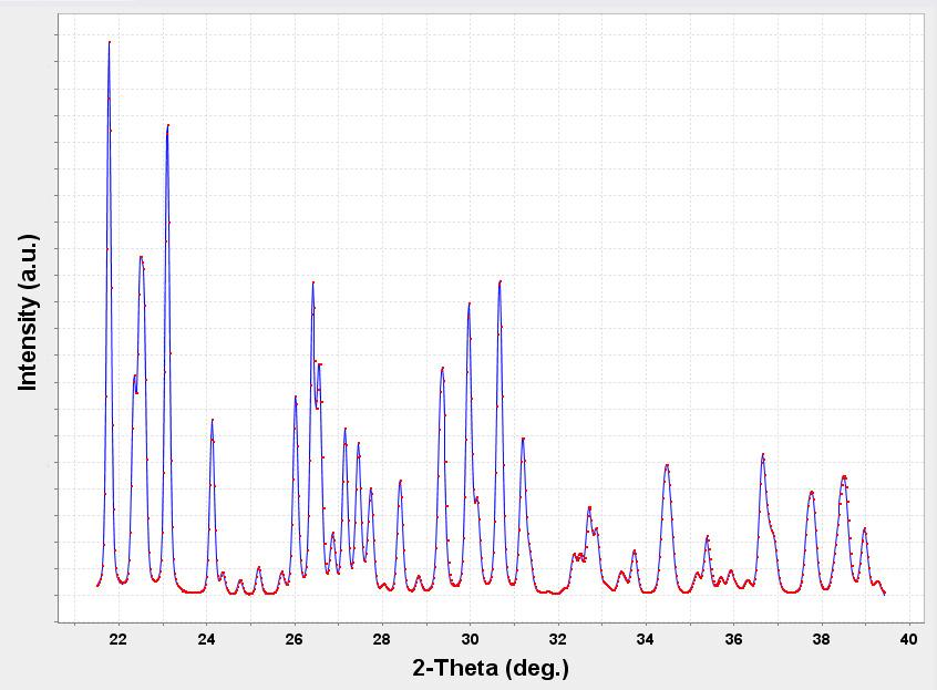
56 Monoclinic zirconia: two ranges collection Intensity (counts) Present work (XRPD) Howard, Hill & Reichert (NPD)* Smith & Newkirk (SCXRD)* a (Å) (2) (1) - b (Å) (2) (1) - c (Å) (3) (1) - ( deg) (4) (1) - Zr x (3) (2) (2) y (3) (2) (2) z (3) (2) (2) O1 x (22) (3) (15) y (21) (3) (14) z (19) (3) (13) O2 x (20) (3) (15) y (20) (3) (14) z (24) (3) (13) R wp (%) GofF θ (degrees)
.")

57 Sample characteristics (1) The sample should be sufficiently large that the beam will be always entirely inside its volume/surface (for Bragg-Brentano check at low angle and sample thickness/transparency). Zeolite sample, changing beam divergence, Krüger and Fischer, J. Appl. Cryst., 37, 472, On the right pattern, at low angle the beam goes out of the sample reducing relative peaks intensities and increasing air scattering/ background
.")

58 Sample characteristics (2) Sample position is critical for good cell parameters (along with perfect alignment of the instrument). The number of diffracting grains at each position should be significant (> 1000 grains). Remember that only a fraction is in condition for the diffraction. Higher beam divergence or size increases this number. So the sample should have millions grains in the diffracting volume.
59 Grain statistics (sufficient)


60 Grain statistics (poor)
61 Sample characteristics The sample should be sufficiently large that the beam will be entirely inside its volume/surface (always) Sample position is critical for good cell parameters (along with perfect alignment of the instrument) The number of diffracting grains at each position should be significant (> 1000 grains). Remember that only a fraction is in condition for the diffraction. Higher beam divergence or size increases this number. Unless a texture analysis is the goal, no preferred orientations should be present. Change sample preparation if necessary. The sample should be homogeneous. Be aware of absorption contrast problems In Bragg-Brentano geometry the thickness should be infinite respect to the absorption. Quality of the surface matters.
62 Ambient conditions In some cases constant ambient condition are important: temperature for cell parameter determination or phase transitions humidity for some organic compounds or pharmaceuticals can your sample be damaged or modify by irradiation (normally Copper or not too highly energetic radiations are not) There are special attachments to control the ambient for sensitive compounds
63 Non classical Rietveld applications Along with the refinement of crystal structures the concept of the Rietveld method has been extended to other diffraction analyses. Most of them more useful for people working on material science. These are: Quantitative phase analyses Amorphous quantification Microstructural analyses Texture and Residual stresses
64 Expert tricks/suggestion First get a good experiment/spectrum Know your sample as much as possible Do not refine too many parameters Always try first to manually fit the spectrum as much as possible Never stop at the first result Look carefully and constantly to the visual fit/plot and residuals during refinement process (no blind refinement) Zoom in the plot and look at the residuals. Try to understand what is causing a bad fit. Do not plot absolute intensities; plot at iso-statistical errors. Small peaks are important like big peaks. Use all the indices and check parameter errors. First get a good experiment/spectrum
Rietveld refinements collection strategies!
 Rietveld refinements collection strategies! Luca Lutterotti! Department of Materials Engineering and Industrial Technologies! University of Trento - Italy! Quality of the experiment! A good refinement,
X-ray Powder Diffraction
 X-ray Powder Diffraction Chemistry 754 Solid State Chemistry Lecture #8 April 15, 2004 Single Crystal Diffraction Diffracted Beam Incident Beam Powder Diffraction Diffracted Beam Incident Beam In powder
1
 In the following tutorial we will determine by fitting the standard instrumental broadening supposing that the LaB 6 NIST powder sample broadening is negligible. This can be achieved in the MAUD program
Structural Refinement based on the Rietveld Method. An introduction to the basics by Cora Lind
 Structural Refinement based on the Rietveld Method An introduction to the basics by Cora Lind Outline What, when and why? - Possibilities and limitations Examples Data collection Parameters and what to
Structural Refinement based on the Rietveld Method
 Structural Refinement based on the Rietveld Method An introduction to the basics by Cora Lind Outline What, when and why? - Possibilities and limitations Examples Data collection Parameters and what to
Crystal Quality Analysis Group
 Crystal Quality Analysis Group Contents Contents 1. Overview...1 2. Measurement principles...3 2.1 Considerations related to orientation and diffraction conditions... 3 2.2 Rocking curve measurement...
Formula for the asymmetric diffraction peak profiles based on double Soller slit geometry
 REVIEW OF SCIENTIFIC INSTRUMENTS VOLUME 69, NUMBER 6 JUNE 1998 Formula for the asymmetric diffraction peak profiles based on double Soller slit geometry Takashi Ida Department of Material Science, Faculty
ACCURATE TEXTURE MEASUREMENTS ON THIN FILMS USING A POWDER X-RAY DIFFRACTOMETER
 ACCURATE TEXTURE MEASUREMENTS ON THIN FILMS USING A POWDER X-RAY DIFFRACTOMETER MARK D. VAUDIN NIST, Gaithersburg, MD, USA. Abstract A fast and accurate method that uses a conventional powder x-ray diffractometer
LECTURE 15. Dr. Teresa D. Golden University of North Texas Department of Chemistry
 LECTURE 15 Dr. Teresa D. Golden University of North Texas Department of Chemistry Typical steps for acquisition, treatment, and storage of diffraction data includes: 1. Sample preparation (covered earlier)
ANOMALOUS SCATTERING FROM SINGLE CRYSTAL SUBSTRATE
 177 ANOMALOUS SCATTERING FROM SINGLE CRYSTAL SUBSTRATE L. K. Bekessy, N. A. Raftery, and S. Russell Faculty of Science, Queensland University of Technology, GPO Box 2434, Brisbane, Queensland, Australia
COMPARISON BETWEEN CONVENTIONAL AND TWO-DIMENSIONAL XRD
 Copyright JCPDS - International Centre for Diffraction Data 2003, Advances in X-ray Analysis, Volume 46. 37 COMPARISON BETWEEN CONVENTIONAL AND TWO-DIMENSIONAL XRD Bob B. He, Uwe Preckwinkel, and Kingsley
XRDUG Seminar III Edward Laitila 3/1/2009
 XRDUG Seminar III Edward Laitila 3/1/2009 XRDUG Seminar III Computer Algorithms Used for XRD Data Smoothing, Background Correction, and Generating Peak Files: Some Features of Interest in X-ray Diffraction
Rietveld-Method part I
 Rietveld-Method part I Dr. Peter G. Weidler Institute of Functional Interfaces IFG 1 KIT 10/31/17 The Research University in the Helmholtz Association Name of Institute, Faculty, Department www.kit.edu
Fundamentals of Rietveld Refinement II. Refinement of a Single Phase
 Fundamentals of Rietveld Refinement II. Refinement of a Single Phase An Introduction to Rietveld Refinement using PANalytical X Pert HighScore Plus v3.0a Scott A Speakman, Ph.D. MIT Center for Materials
Figure 1: Derivation of Bragg s Law
 What is Bragg s Law and why is it Important? Bragg s law refers to a simple equation derived by English physicists Sir W. H. Bragg and his son Sir W. L. Bragg in 1913. This equation explains why the faces
Quantitative Rietveld analysis in batch mode with Maud
 Quantitative Rietveld analysis in batch mode with Maud Luca Lutterotti Dipartimento di Ingegneria dei Materiali e delle Tecnologie Industriali Università di Trento, 38050 Trento, Italy E-mail: Luca.Lutterotti@ing.unitn.it
Diffraction Basics (prepared by James R. Connolly, for EPS , Introduction to X-Ray Powder Diffraction, Spring 2012
 Introduction The use of X-rays for crystallographic analysis relies on a few basic principals:. When an incident beam of x-rays interacts with a target material, one of the primary effects observed is
Stress and Texture by XRD Bob He, Bruker AXS
 Stress and Texture by XRD Bob He, Bruker AXS Intensity Conventional X-ray Diffractometer Divergence slit Antiscatter slit Monochromator Bragg-Brentano Geometry. Scanning over range to collect XRD pattern.
X-ray Diffraction from Materials
 X-ray Diffraction from Materials 2008 Spring Semester Lecturer; Yang Mo Koo Monday and Wednesday 14:45~16:00 8. Experimental X-ray Diffraction Procedures 8.1 Diffraction Experiments using Films 8.1.1 Laue
DETERMINATION OF THE ORIENTATION OF AN EPITAXIAL THIN FILM BY A NEW COMPUTER PROGRAM CrystalGuide
 The Rigaku Journal Vol. 16/ number 1/ 1999 Technical Note DETERMINATION OF THE ORIENTATION OF AN EPITAXIAL THIN FILM BY A NEW COMPUTER PROGRAM CrystalGuide R. YOKOYAMA AND J. HARADA X-Ray Research Laboratory,
Fundamentals of Rietveld Refinement III. Refinement of a Mixture
 Fundamentals of Rietveld Refinement III. Refinement of a Mixture An Introduction to Rietveld Refinement using PANalytical X Pert HighScore Plus v3.0e Scott A Speakman, Ph.D. MIT Center for Materials Science
Diffraction I - Geometry. Chapter 3
 Diffraction I - Geometry Chapter 3 Outline ❽ Diffraction basics ❽ Braggs law ❽ Laue equations ❽ Reciprocal space and diffraction ❽ Units for x-ray wavelengths ❽ Diffraction methods Laue photographs Rotation
Fundamentals of Rietveld Refinement III. Additional Examples
 Fundamentals of Rietveld Refinement III. Additional Examples An Introduction to Rietveld Refinement using PANalytical X Pert HighScore Plus v3.0d Scott A Speakman, Ph.D. MIT Center for Materials Science
Wave Phenomena Physics 15c. Lecture 19 Diffraction
 Wave Phenomena Physics 15c Lecture 19 Diffraction What We Did Last Time Studied interference > waves overlap Amplitudes add up Intensity = (amplitude) does not add up Thin-film interference Reflectivity
Brief Instructions. The MATLAB working directory should be populated with the following files:
 MOF-FIT A Matlab routine for determining breathing angles and other crystal structure deformations of MOFs using a visual fit and a graphical user interface Brief Instructions The MATLAB working directory
Chapter 36. Diffraction. Copyright 2014 John Wiley & Sons, Inc. All rights reserved.
 Chapter 36 Diffraction Copyright 36-1 Single-Slit Diffraction Learning Objectives 36.01 Describe the diffraction of light waves by a narrow opening and an edge, and also describe the resulting interference
Maud: a Rietveld analysis program designed for the internet and experiment integration
 Maud: a Rietveld analysis program designed for the internet and experiment integration Luca Lutterotti Department of Materials Engineering University of Trento Italy The problem Carl is a PhD student in
Collect and Reduce Intensity Data Photon II
 Collect and Reduce Intensity Data Photon II General Steps in Collecting Intensity Data Note that the steps outlined below are generally followed when using all modern automated diffractometers, regardless
Introduction to two-dimensional X-ray diffraction
 Introduction to two-dimensional X-ray diffraction Bob Baoping He a) Bruker Advanced X-ray Solutions, Inc., 5465 East Cheryl Parkway, Madison, Wisconsin 53711 Received 7 February 2003; accepted 1 April
THE INFLUENCE OF SURFACE ROUGHNESS ON THE REFRACTION OF X-RAYS AND ITS EFFECT ON BRAGG PEAK POSITIONS
 Copyright JCPDS - International Centre for Diffraction Data 2003, Advances in X-ray Analysis, Volume 46. 232 THE INFLUENCE OF SURFACE ROUGHNESS ON THE REFRACTION OF X-RAYS AND ITS EFFECT ON BRAGG PEAK
Maintenance Package Measurement
 Maintenance Package Measurement Contents Contents 1. Package measurement flow...1 2. Measurement procedures...3 2.1 Startup... 3 2.2 Hardware setup... 4 2.3 Setting Package measurement conditions... 7
Fundamentals of Rietveld Refinement II. Refinement of a Single Phase
 Fundamentals of Rietveld Refinement II. Refinement of a Single Phase An Introduction to Rietveld Refinement using PANalytical X Pert HighScore Plus v3.0e Scott A Speakman, Ph.D. MIT Center for Materials
Collect and Reduce Intensity Data -- APEX
 Collect and Reduce Intensity Data -- APEX General Steps in Collecting Intensity Data Note that the steps outlined below are generally followed when using all modern automated diffractometers, regardless
How to Analyze Materials
 INTERNATIONAL CENTRE FOR DIFFRACTION DATA How to Analyze Materials A PRACTICAL GUIDE FOR POWDER DIFFRACTION To All Readers This is a practical guide. We assume that the reader has access to a laboratory
d has a relationship with ψ
 Principle of X-Ray Stress Analysis Metallic materials consist of innumerable crystal grains. Each grain usually faces in a random direction. When stress is applied on such materials, the interatomic distance
Using the Sample Changer
 Using the Sample Changer with the High-Speed Bragg-Brentano Optics on the PANalytical X Pert Pro MPD Scott A Speakman, Ph.D Center for Materials Science and Engineering at MIT Speakman@mit.edu 617-253-6887
1. Polarization effects in optical spectra of photonic crystals
 Speech for JASS 05. April 2005. Samusev A. 1. Polarization effects in optical spectra of photonic crystals Good afternoon. I would like to introduce myself. My name is Anton Samusev. I m a student of Saint
0.2 Is the second sample structure solvable with this quality of data? Yes [x] No [ ]
![0.2 Is the second sample structure solvable with this quality of data? Yes [x] No [ ]](/thumbs/82/84893037.jpg "0.2 Is the second sample structure solvable with this quality of data? Yes [x] No [ ]") QUESTIONNAIRE FOR the STRUCTURE DETERMINATION BY POWDER DIFFRACTOMETRY ROUND ROBIN - 2 Sample 1 0.2 Is the second sample structure solvable with this quality of data? Yes [x] No [ ] 1. Preliminary work
QUESTIONNAIRE FOR the STRUCTURE DETERMINATION BY POWDER DIFFRACTOMETRY ROUND ROBIN - 2 Sample 1 0.2 Is the second sample structure solvable with this quality of data? Yes [x] No [ ] 1. Preliminary work
3.014 Derivative Structures Data Analysis using PANalytical X Pert HighScore Plus v3.0
 3.014 Derivative Structures Data Analysis using PANalytical X Pert HighScore Plus v3.0 For most analyses, you will need to open the data and the corresponding entry in the reference database. You will
Experimental Competition. Sample Solution
 The 37th International Physics Olympiad Singapore Experimental Competition Wednesday, 1 July, 006 Sample Solution a. A sketch of the experimental setup Part 1 Receiver Rotating table Goniometer Fixed arm
Powder Diffraction Data for Pure KHP
 Powder Diffraction Data for Pure KHP This is the simple example template containing only headers for each report item and the bookmarks. The invisible bookmarks are indicated by text between brackets.
dq dt I = Irradiance or Light Intensity is Flux Φ per area A (W/m 2 ) Φ =
 Φ =") Radiometry (From Intro to Optics, Pedrotti -4) Radiometry is measurement of Emag radiation (light) Consider a small spherical source Total energy radiating from the body over some time is Q total Radiant
Radiometry (From Intro to Optics, Pedrotti -4) Radiometry is measurement of Emag radiation (light) Consider a small spherical source Total energy radiating from the body over some time is Q total Radiant
Bruker AXS D8 FOCUS. Diffraction Solutions XRD. think forward
 Bruker AXS D8 FOCUS Diffraction Solutions think forward XRD The concept behind the D8 FOCUS is to provide you with a reliable workhorse for powder diffraction applications attractively priced entry-level
Contributions to the defocusing effect on pole figure measurements by X-ray diffraction
 RESEARCH Revista Mexicana de Física 61 (215) 296 3 JULY-AUGUST 215 Contributions to the defocusing effect on pole figure measurements by X-ray diffraction J. Palacios Gómez, R.S. Salat Figols, A. Jiménez
Limits of powder indexing of impure samples using whole profile methods. A. Le Bail Université du Maine Laboratoire des Fluorures CNRS UMR 6010
 Limits of powder indexing of impure samples using whole profile methods A. Le Bail Université du Maine Laboratoire des Fluorures CNRS UMR 6010 Content of the talk - Introduction - Starting and discussing
Data integration and scaling
 Data integration and scaling Harry Powell MRC Laboratory of Molecular Biology 3rd February 2009 Abstract Processing diffraction images involves three basic steps, which are indexing the images, refinement
Lesson 2 Instrument Configurations for Profex / BGMN
 Lesson 2 Instrument Configurations for Profex / BGMN Nicola Döbelin RMS Foundation, Bettlach, Switzerland June 13 15, 2018, Bettlach, CH Fundamental Parameters Approach http://www.bgmn.de 2 BGMN: Wavelength
Diffraction. Single-slit diffraction. Diffraction by a circular aperture. Chapter 38. In the forward direction, the intensity is maximal.
 Diffraction Chapter 38 Huygens construction may be used to find the wave observed on the downstream side of an aperture of any shape. Diffraction The interference pattern encodes the shape as a Fourier
Wave Optics. April 11, 2014 Chapter 34 1
 Wave Optics April 11, 2014 Chapter 34 1 Announcements! Exam tomorrow! We/Thu: Relativity! Last week: Review of entire course, no exam! Final exam Wednesday, April 30, 8-10 PM Location: WH B115 (Wells Hall)
APPLICATION OF Ni/C-GÖBEL MIRRORS AS PARALLEL BEAM X-RAY OPTICS FOR Cu Ka AND Mo Ka RADIATION
 Copyright(c)JCPDS-International Centre for Diffraction Data 2000,Advances in X-ray Analysis,Vol.43 212 APPLICATION OF Ni/C-GÖBEL MIRRORS AS PARALLEL BEAM X-RAY OPTICS FOR AND RADIATION T. Holz, R. Dietsch,
DASH User Guide and Tutorials
 DASH User Guide and Tutorials 2017 CSD Release Copyright 2016 Cambridge Crystallographic Data Centre Registered Charity No 800579 Contents 1 Introduction...1 1.1 The DASH Program...1 1.2 Basic Steps for
Indexing a Powder Pattern
 Indexing a Powder Pattern Manual Indexing of Cubic Compounds Primitive Cubic Systems Cubic Cells with Systematic Absences Zero Point/Sample Displacement Errors Autoindexing (indexing with a computer) Data
LECTURE 16. Dr. Teresa D. Golden University of North Texas Department of Chemistry
 LECTURE 16 Dr. Teresa D. Golden University of North Texas Department of Chemistry A. Evaluation of Data Quality An ICDD study found that 50% of x-ray labs overestimated the accuracy of their data by an
CCP4-BGU workshop 2018 The X-ray Diffraction Experiment Diffraction Geometry and Data Collection Strategy. Andrew GW Leslie, MRC LMB, Cambridge, UK
 CCP4-BGU workshop 2018 The X-ray Diffraction Experiment Diffraction Geometry and Data Collection Strategy Andrew GW Leslie, MRC LMB, Cambridge, UK Definition of a crystal and the unit cell Crystal: An
dq dt I = Irradiance or Light Intensity is Flux Φ per area A (W/m 2 ) Φ =
 Φ =") Radiometry (From Intro to Optics, Pedrotti -4) Radiometry is measurement of Emag radiation (light) Consider a small spherical source Total energy radiating from the body over some time is Q total Radiant
Radiometry (From Intro to Optics, Pedrotti -4) Radiometry is measurement of Emag radiation (light) Consider a small spherical source Total energy radiating from the body over some time is Q total Radiant
Chapter 38. Diffraction Patterns and Polarization
 Chapter 38 Diffraction Patterns and Polarization Diffraction Light of wavelength comparable to or larger than the width of a slit spreads out in all forward directions upon passing through the slit This
Towards 0.1 mm spatial resolution
 Submitted for publication in ICNS Proceedings Towards 0.1 mm spatial resolution A. D. Stoica and X. L. Wang Spallation Neutron Source 701 Scarboro Road Oak Ridge National Laboratory Oak Ridge, TN 37831,
Cover Page. The handle holds various files of this Leiden University dissertation
 Cover Page The handle http://hdl.handle.net/1887/48877 holds various files of this Leiden University dissertation Author: Li, Y. Title: A new method to reconstruct the structure from crystal images Issue
Physical Optics. You can observe a lot just by watching. Yogi Berra ( )
") Physical Optics You can observe a lot just by watching. Yogi Berra (1925-2015) OBJECTIVES To observe some interference and diffraction phenomena with visible light. THEORY In a previous experiment you
Physical Optics You can observe a lot just by watching. Yogi Berra (1925-2015) OBJECTIVES To observe some interference and diffraction phenomena with visible light. THEORY In a previous experiment you
Basics of X-Area for image plates
 Basics of X-Area for image plates Commercial software to process single-crystal and powder x-ray data from STOE image plates and PILATUS detectors Andrzej Grzechnik 1 & Karen Friese 2 1 Institute of Crystallography,
Two-dimensional Powder Diffraction. Bob He, Bruker AXS
 Two-dimensional Powder Diffraction Bob He, Bruker AXS XRD : Comparison with Conventional XRD (1) The powder diffraction pattern in 3D space (blue) and the conventional diffractometer plane. Intensity Conventional
X PERT DATA COLLECTOR. Quick Start Guide
 X PERT DATA COLLECTOR Quick Start Guide X Pert Data Collector Quick Start Guide EDITION NOTICE: Sixth Edition, January 2006. This is the sixth edition of this publication, it is intended for use with
Grazing Angle 2 Theta Phase Analysis
 Page 1 of 7 Grazing Angle 2 Theta Phase Analysis 1. Log into the User Log System on the SMIF web site Hardware Setup X-Ray Tube The line focus configuration of the x-ray tube is used. This is the default
Chapter 24. Wave Optics
 Chapter 24 Wave Optics Wave Optics The wave nature of light is needed to explain various phenomena Interference Diffraction Polarization The particle nature of light was the basis for ray (geometric) optics
RIETVELD REFINEMENT OF POWDER DATA FROM MULTILAYER OPTICS
 Copyright (c)jcpds-international Centre for Diffraction Data 2002, Advances in X-ray Analysis, Volume 45. 166 RIETVELD REFINEMENT OF POWDER DATA FROM MULTILAYER OPTICS ABSTRACT Scott T. Misture NYS College
Crystal Structure Refinement
 Crystal Structure Refinement Dr. Falak Sher Pakistan Institute of Engineering and Applied Sciences Islamabad 09/10/2010 The Rietveld Method Rietveld structure refinement is a method for estimating the
Chapter 24. Wave Optics
 Chapter 24 Wave Optics Diffraction Huygen s principle requires that the waves spread out after they pass through slits This spreading out of light from its initial line of travel is called diffraction
Tutorial: Crystal structure refinement of oxalic acid dihydrate using GSAS
 Tutorial: Crystal structure refinement of oxalic acid dihydrate using GSAS The aim of this tutorial is to use GSAS to locate hydrogen in oxalic acid dihydrate and refine the crystal structure. By no means
Quick Start Guide. X Pert Data Collector
 Quick Start Guide X Pert Data Collector X PERT DATA COLLECTOR QUICK START GUIDE EDITION NOTICE: Fifth Edition, October 2004. This is the fifth edition of this publication, it is intended for use with
CHAPTER 26 INTERFERENCE AND DIFFRACTION
 CHAPTER 26 INTERFERENCE AND DIFFRACTION INTERFERENCE CONSTRUCTIVE DESTRUCTIVE YOUNG S EXPERIMENT THIN FILMS NEWTON S RINGS DIFFRACTION SINGLE SLIT MULTIPLE SLITS RESOLVING POWER 1 IN PHASE 180 0 OUT OF
X-Ray fluorescence and Raman spectroscopy
 X-Ray fluorescence and Raman spectroscopy Advanced physics laboratory (nd part) 4CFU Catalini Letizia, De Angelis Giulia Vittoria, Piselli Verdiana Abstract In this paper we report about two different
Using the Furnace. with the High-Speed Bragg-Brentano Optics on the PANalytical X Pert Pro MPD
 Using the Furnace with the High-Speed Bragg-Brentano Optics on the PANalytical X Pert Pro MPD Scott A Speakman, Ph.D Center for Materials Science and Engineering at MIT Speakman@mit.edu 617-253-6887 http://prism.mit.edu/xray
Analysis of a Cubic Crystal Gravitation Deflector (P) 5
 5") SECTION 4 Analysis of a Cubic Crystal Gravitation Deflector (P) 5 TAPPING THE ENERGY OF THE GRAVITATIONAL FIELD The general vertically upward outward Flow of gravitational energy can be tapped by deflecting
SECTION 4 Analysis of a Cubic Crystal Gravitation Deflector (P) 5 TAPPING THE ENERGY OF THE GRAVITATIONAL FIELD The general vertically upward outward Flow of gravitational energy can be tapped by deflecting
Chapter 36. Diffraction. Dr. Armen Kocharian
 Chapter 36 Diffraction Dr. Armen Kocharian Diffraction Light of wavelength comparable to or larger than the width of a slit spreads out in all forward directions upon passing through the slit This phenomena
Chapter 24. Wave Optics. Wave Optics. The wave nature of light is needed to explain various phenomena
 Chapter 24 Wave Optics Wave Optics The wave nature of light is needed to explain various phenomena Interference Diffraction Polarization The particle nature of light was the basis for ray (geometric) optics
diffraction patterns obtained with convergent electron beams yield more information than patterns obtained with parallel electron beams:
 CBED-Patterns Principle of CBED diffraction patterns obtained with convergent electron beams yield more information than patterns obtained with parallel electron beams: specimen thickness more precise
CHEM-E5225 :Electron Microscopy Imaging I
 CHEM-E5225 :Electron Microscopy Imaging I 2018.11 Yanling Ge Outline Amplitude Contrast Phase Contrast Images Thickness and Bending Effects Amplitude Contrast Amplitude phase TEM STEM Incoherent elastic
6-1 LECTURE #6: OPTICAL PROPERTIES OF SOLIDS. Basic question: How do solids interact with light? The answers are linked to:
 LECTURE #6: OPTICAL PROPERTIES OF SOLIDS Basic question: How do solids interact with light? The answers are linked to: Properties of light inside a solid Mechanisms behind light reflection, absorption
Optics Vac Work MT 2008
 Optics Vac Work MT 2008 1. Explain what is meant by the Fraunhofer condition for diffraction. [4] An aperture lies in the plane z = 0 and has amplitude transmission function T(y) independent of x. It is
Physics 123 Optics Review
 Physics 123 Optics Review I. Definitions & Facts concave converging convex diverging real image virtual image real object virtual object upright inverted dispersion nearsighted, farsighted near point,
ifit : a simple generic data analysis framework
 -farhi@ill.fr - 1 ifit : a simple generic data analysis framework Example use with full Reitveld analysis using virtual experiments. E. Farhi History and development First
Chapter 35 &36 Physical Optics
 Chapter 35 &36 Physical Optics Physical Optics Phase Difference & Coherence Thin Film Interference 2-Slit Interference Single Slit Interference Diffraction Patterns Diffraction Grating Diffraction & Resolution
specular diffuse reflection.
 Lesson 8 Light and Optics The Nature of Light Properties of Light: Reflection Refraction Interference Diffraction Polarization Dispersion and Prisms Total Internal Reflection Huygens s Principle The Nature
HKL2000. Data processing X-ray data processing = changing detector output to estimate of square of structure factors amplitudes
 HKL000 Dominika Borek UT Southwestern Medical Center at Dallas Data processing X-ray data processing = changing detector output to estimate of square of structure factors amplitudes F Data processing in
A CONVERGENT BEAM, PARALLEL DETECTION X-RAY DIFFRACTION SYSTEM FOR CHARACTERIZING COMBINATORIAL EPITAXIAL THIN FILMS
 The Rigaku Journal Vol. 18/ No. 1/ 2001 CONTRIBUTED PAPERS A CONVERGENT BEAM, PARALLEL DETECTION X-RAY DIFFRACTION SYSTEM FOR CHARACTERIZING COMBINATORIAL EPITAXIAL THIN FILMS K. OMOTE, T. KIKUCHI, J.
Properties of Light. 1. The Speed of Light 2. The Propagation of Light 3. Reflection and Refraction 4. Polarization
 Chapter 33 - Light Properties of Light 1. The Speed of Light 2. The Propagation of Light 3. Reflection and Refraction 4. Polarization MFMcGraw-PHY 2426 Chap33-Light - Revised: 6-24-2012 2 Electromagnetic
Waves & Oscillations
 Physics 42200 Waves & Oscillations Lecture 41 Review Spring 2016 Semester Matthew Jones Final Exam Date:Tuesday, May 3 th Time:7:00 to 9:00 pm Room: Phys 112 You can bring one double-sided pages of notes/formulas.
normal angle of incidence increases special angle no light is reflected
 Reflection from transparent materials (Chapt. 33 last part) When unpolarized light strikes a transparent surface like glass there is both transmission and reflection, obeying Snell s law and the law of
PHYSICS 106 TEST #3 May 5, 2010
 NAME: PHYSICS 106 TEST #3 May 5, 010 ID NUMBER: LECTURE SECTION: [ ] A1 (8 am) [ ] B1/HP ( pm) [ ] C1 (6 pm) INSTRUCTIONS: 1. Do not turn over this cover sheet until instructed to do so.. No talking is
Chapter 37. Wave Optics
 Chapter 37 Wave Optics Wave Optics Wave optics is a study concerned with phenomena that cannot be adequately explained by geometric (ray) optics. Sometimes called physical optics These phenomena include:
Effective Medium Theory, Rough Surfaces, and Moth s Eyes
 Effective Medium Theory, Rough Surfaces, and Moth s Eyes R. Steven Turley, David Allred, Anthony Willey, Joseph Muhlestein, and Zephne Larsen Brigham Young University, Provo, Utah Abstract Optics in the
Chapter 2: Wave Optics
 Chapter : Wave Optics P-1. We can write a plane wave with the z axis taken in the direction of the wave vector k as u(,) r t Acos tkzarg( A) As c /, T 1/ and k / we can rewrite the plane wave as t z u(,)
SUPPLEMENTARY INFORMATION
 SUPPLEMENTARY INFORMATION doi:10.1038/nature10934 Supplementary Methods Mathematical implementation of the EST method. The EST method begins with padding each projection with zeros (that is, embedding
Single Slit Diffraction
 Name: Date: PC1142 Physics II Single Slit Diffraction 5 Laboratory Worksheet Part A: Qualitative Observation of Single Slit Diffraction Pattern L = a 2y 0.20 mm 0.02 mm Data Table 1 Question A-1: Describe
Spectrographs. C. A. Griffith, Class Notes, PTYS 521, 2016 Not for distribution.
 Spectrographs C A Griffith, Class Notes, PTYS 521, 2016 Not for distribution 1 Spectrographs and their characteristics A spectrograph is an instrument that disperses light into a frequency spectrum, which
Using the Bruker Tracer III-SD Handheld X-Ray Fluorescence Spectrometer using PC Software for Data Collection
 Using the Bruker Tracer III-SD Handheld X-Ray Fluorescence Spectrometer using PC Software for Data Collection Scott A Speakman, Ph.D Center for Materials Science and Engineering at MIT For assistance in
Chapter 24. Wave Optics. Wave Optics. The wave nature of light is needed to explain various phenomena
 Chapter 24 Wave Optics Wave Optics The wave nature of light is needed to explain various phenomena Interference Diffraction Polarization The particle nature of light was the basis for ray (geometric) optics
1 Introduction. 2 Program Development. Abstract. 1.1 Test Crystals
 Sysabs - A program for the visualization of crystal data symmetry in reciprocal space B. C. Taverner Centre for Molecular Design, University of the Witwatersrand, Johannesburg, South Africa Craig@hobbes.gh.wits.ac.za
Lesson 6 Profex Graphical User Interface for BGMN and Fullprof
 Lesson 6 Profex Graphical User Interface for BGMN and Fullprof Nicola Döbelin RMS Foundation, Bettlach, Switzerland June 07 09, 2017, Oslo, N Background Information Developer: License: Founded in: 2003
Crystallography & Cryo-electron microscopy
 Crystallography & Cryo-electron microscopy Methods in Molecular Biophysics, Spring 2010 Sample preparation Symmetries and diffraction Single-particle reconstruction Image manipulation Basic idea of diffraction: