X-ray Diffraction from Materials
|
|
|
- Ronald Hill
- 5 years ago
- Views:
Transcription
1 X-ray Diffraction from Materials 2008 Spring Semester Lecturer; Yang Mo Koo Monday and Wednesday 14:45~16:00
2 8. Experimental X-ray Diffraction Procedures 8.1 Diffraction Experiments using Films Laue camera Rotating crystal camera Weissenberg camera Precession (Buerger) camera 8.2 X-ray Diffractometers Diffractometer with 2-circle goniometer Diffractometer with 4-circle goniometer 8.3 The Integrated X-ray Intensity of a Diffraction Peak Diffraction from small crystal Diffraction from mosaic crystal Lorentz factor Temperature effect Home work
3 X ray : e i k r f ( r ) 8. Experimental X-ray Diffraction Procedures x ray : e ik r detector F 1 + i r ( k ) = f ( r) e k dr 3/ 2 ( 2π ) f ) f (r) (i) X-ray sources - vacuum sealed tube (chapter 2) - synchrotron radiation (chapter 2) - x-ray optical elements (chapter 3) (ii) Crystals - crystal structure and its symmetry (chapter 6) - interaction between crystal and x-ray (chapter 7) - crystal moving stage (chapter 8) (iii) Detectors (chapter 4) - film - electronics


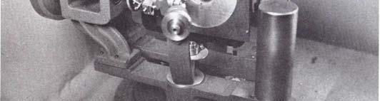
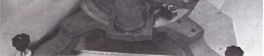
4 8.1.1 Laue camera Polaroid cassette Back-reflection camera
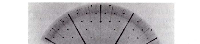
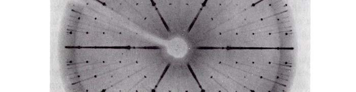
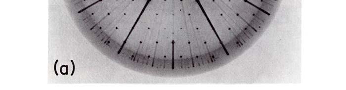
5 Schematic diagrams of the diffraction pattern Elliptic curve shape (not elliptic curve) hyperbola
6 Diffraction condition for Laue geometry If the reciprocal point hkl s locate inside of large Ewald sphere and outside of small Ewald sphere, diffraction spot of (hkl) hits the film.
7 Intersection ti of a conical array of diffracted d peaks makes a elliptic curve shape for transmission case and makes hyperbola for back reflection case. All of the planes of one zone reflected beams which lie on the surface of a cone whose axis is the zone axis and whose semi-apex angle φ is equal to the angle Φ at which the zone is inclined to the transmitted beam. 0<Φ<π/4 : transmission elliptic curve shape π/4<φ<π/2 : transmission hyperbola φ
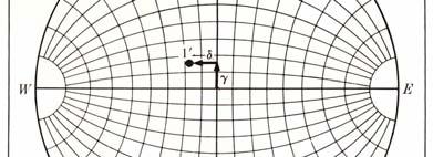
8 Reflecting plane: belong to a zone whose axis lies in yz-plane CN: normal to the reflecting gplane PQ: trace of diffraction peaks AN: trace of plane normal long to a zone. Incident beam,,p plane normal, and diffracted beam are coplanar. Therefore, the direction of reflecting plane can be calculated if the position of N is estimated by diffraction spot S. refracting plane Crystal orientation can be obtained from the γ and δ of the diffraction spots. tan μ = FN FO ON tan σ = OC CF tanδδ tanδδ = = CF sin γ sin γ FN 1 = = sin μ CF cosγ tanδ sin μ cosγ


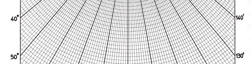
9 Greninger chart: direct read of γ and δ from diffraction peaks. Leonhardt chart: transmission Laue experiment
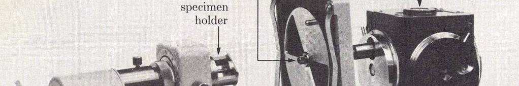
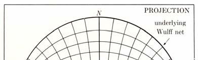
10 Crystal orientation determination Laue back reflection; -measure γ and δ of spots Crystal orientation Plot of reflecting plane normal at Wulff net using γ and δ.


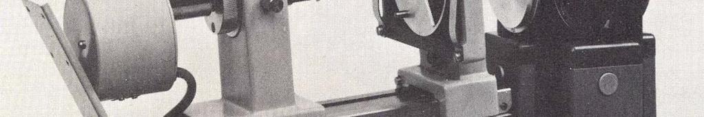
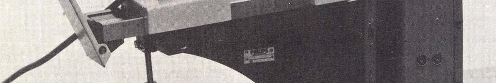
11 Rotating ti Crystal Camera
12 Diffraction condition Diffraction pattern
13 Indexing of diffraction peaks since * ( S S ) c = r 0 hkl c = l S = 1/ λ and S0 c = 0 c S c = l sin β = l λ the lattice parameter c becomes λl c = = sin β λl cosφ Indexing of h and k 2 * 2 β + λ r = 2 ( 1 cos α cos β ) 2 sin rh where r * h = ha * + kb *


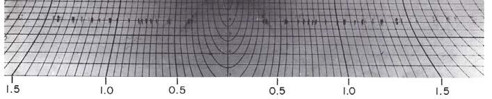
14 λ r and λ r Bernal chart: read of * and r * from film. v h

15 Oscillation crystal method: * * * There are a few combination which satisfies the condition; rh = ha + kb It causes the overlapping of different diffraction peaks. One can reduce overlapping by oscillating crystal or moving film (Weissenberg camera) a)
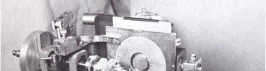
16 Weissenberg camera
17 Film coordinate and diffraction condition x: film moving direction y: rotation direction ω: rotation angle of crystal k: the ratio between x/ω ~ 0.5mm/min
18 Relationship between x and y for l=0 x = kωω y = R2θ Let s see the diffraction condition for P0. To occur diffraction at P0, rotation angle of crystal would be π ω = θ + φ 2
19 Coordinate of diffraction peak of P0 at film; π x = k θ + φ 2 and 2R y = x + R k ( π + 2φ ) The reciprocal point which has the same φ lies on straight line. Since a monochromatic x-ray is used in Weissenberg camera, the reciprocal points lie inside of large circle can be diffract by crystal rotation. When the polar mesh of the large circle transforms to film using the above equation;
20
21 When this large circle is divided by latitude such as k=1, 2, 3,, the shape of transformed latitude becomes


22 When this large circle is divided by two perpendicular line mesh such as k=0, 1, 2, 3, and h=0, 1, 2, 3, the shape of transformed mesh becomes
23
24 Equi-inclination method for l 0 Rotation axis of reciprocal lattice locates out side of circle of Ewald sphere. The points of which φ is same will not transform straight line. Rotation axis can be adjusted by inclining incident x-ray. same shape of diffraction pattern for l=0.


25 Precession (Buerger) camera
26 Precession motion and diffraction pattern
27 Precession motion and diffraction condition for l=0
28 Precession motion and diffraction condition for l 0
Diffraction I - Geometry. Chapter 3
 Diffraction I - Geometry Chapter 3 Outline ❽ Diffraction basics ❽ Braggs law ❽ Laue equations ❽ Reciprocal space and diffraction ❽ Units for x-ray wavelengths ❽ Diffraction methods Laue photographs Rotation
Figure 1: Derivation of Bragg s Law
 What is Bragg s Law and why is it Important? Bragg s law refers to a simple equation derived by English physicists Sir W. H. Bragg and his son Sir W. L. Bragg in 1913. This equation explains why the faces
Diffraction Basics (prepared by James R. Connolly, for EPS , Introduction to X-Ray Powder Diffraction, Spring 2012
 Introduction The use of X-rays for crystallographic analysis relies on a few basic principals:. When an incident beam of x-rays interacts with a target material, one of the primary effects observed is
X-Ray Diffraction Edited 10/6/15 by Stephen Albright & DGH & JS
 X-Ray Diffraction Edited 10/6/15 by Stephen Albright & DGH & JS Introduction and concepts The experiment consists of two parts. The first is to identify an unknown sample using the powder method; the second
13. Brewster angle measurement
 13. Brewster angle measurement Brewster angle measurement Objective: 1. Verification of Malus law 2. Measurement of reflection coefficient of a glass plate for p- and s- polarizations 3. Determination
Be careful not to leave your fingerprints on the optical surfaces of lenses or Polaroid sheets.
 POLARIZATION OF LIGHT REFERENCES Halliday, D. and Resnick, A., Physics, 4 th edition, New York: John Wiley & Sons, Inc, 1992, Volume II, Chapter 48-1, 48-2, 48-3. (2weights) (1weight-exercises 1 and 3
Optics Vac Work MT 2008
 Optics Vac Work MT 2008 1. Explain what is meant by the Fraunhofer condition for diffraction. [4] An aperture lies in the plane z = 0 and has amplitude transmission function T(y) independent of x. It is
CCP4-BGU workshop 2018 The X-ray Diffraction Experiment Diffraction Geometry and Data Collection Strategy. Andrew GW Leslie, MRC LMB, Cambridge, UK
 CCP4-BGU workshop 2018 The X-ray Diffraction Experiment Diffraction Geometry and Data Collection Strategy Andrew GW Leslie, MRC LMB, Cambridge, UK Definition of a crystal and the unit cell Crystal: An
12 - THREE DIMENSIONAL GEOMETRY Page 1 ( Answers at the end of all questions ) = 2. ( d ) - 3. ^i - 2. ^j c 3. ( d )
 = 2. ( d ) - 3. ^i - 2. ^j c 3. ( d )") - THREE DIMENSIONAL GEOMETRY Page ( ) If the angle θ between the line x - y + x + y - z - and the plane λ x + 4 0 is such that sin θ, then the value of λ is - 4-4 [ AIEEE 00 ] ( ) If the plane ax - ay
- THREE DIMENSIONAL GEOMETRY Page ( ) If the angle θ between the line x - y + x + y - z - and the plane λ x + 4 0 is such that sin θ, then the value of λ is - 4-4 [ AIEEE 00 ] ( ) If the plane ax - ay
Experiment 8 Wave Optics
 Physics 263 Experiment 8 Wave Optics In this laboratory, we will perform two experiments on wave optics. 1 Double Slit Interference In two-slit interference, light falls on an opaque screen with two closely
DETERMINATION OF THE ORIENTATION OF AN EPITAXIAL THIN FILM BY A NEW COMPUTER PROGRAM CrystalGuide
 The Rigaku Journal Vol. 16/ number 1/ 1999 Technical Note DETERMINATION OF THE ORIENTATION OF AN EPITAXIAL THIN FILM BY A NEW COMPUTER PROGRAM CrystalGuide R. YOKOYAMA AND J. HARADA X-Ray Research Laboratory,
Module 4. Stereographic projection: concept and application. Lecture 4. Stereographic projection: concept and application
 Module 4 Stereographic projection: concept and application Lecture 4 Stereographic projection: concept and application 1 NPTEL Phase II : IIT Kharagpur : Prof. R. N. Ghosh, Dept of Metallurgical and Materials
POLARIZATION 3.5 RETARDATION PLATES
 Nicol Prism as Polarizer and Analyzer: Nicol prism can be used both as polarizer and as an analyzer. When two Nicol prisms are mounted co axially, then the first Nicol prism N 1 which produces plane polarized
IB-2 Polarization Practice
 Name: 1. Plane-polarized light is incident normally on a polarizer which is able to rotate in the plane perpendicular to the light as shown below. In diagram 1, the intensity of the incident light is 8
Chapter 38. Diffraction Patterns and Polarization
 Chapter 38 Diffraction Patterns and Polarization Diffraction Light of wavelength comparable to or larger than the width of a slit spreads out in all forward directions upon passing through the slit This
Chapter 33 cont. The Nature of Light and Propagation of Light (lecture 2) Dr. Armen Kocharian
 Dr. Armen Kocharian") Chapter 33 cont The Nature of Light and Propagation of Light (lecture 2) Dr. Armen Kocharian Polarization of Light Waves The direction of polarization of each individual wave is defined to be the direction
Chapter 33 cont The Nature of Light and Propagation of Light (lecture 2) Dr. Armen Kocharian Polarization of Light Waves The direction of polarization of each individual wave is defined to be the direction
PHYS 3410/6750: Modern Optics Midterm #2
 Name: PHYS 3410/6750: Modern Optics Midterm #2 Wednesday 16 November 2011 Prof. Bolton Only pen or pencil are allowed. No calculators or additional materials. PHYS 3410/6750 Fall 2011 Midterm #2 2 Problem
Geometric Optics. The Law of Reflection. Physics Waves & Oscillations 3/20/2016. Spring 2016 Semester Matthew Jones
 Physics 42200 Waves & Oscillations Lecture 27 Propagation of Light Hecht, chapter 5 Spring 2016 Semester Matthew Jones Geometric Optics Typical problems in geometric optics: Given an optical system, what
Chapter 24. Wave Optics
 Chapter 24 Wave Optics Wave Optics The wave nature of light is needed to explain various phenomena Interference Diffraction Polarization The particle nature of light was the basis for ray (geometric) optics
Jim Lambers MAT 169 Fall Semester Lecture 33 Notes
 Jim Lambers MAT 169 Fall Semester 2009-10 Lecture 33 Notes These notes correspond to Section 9.3 in the text. Polar Coordinates Throughout this course, we have denoted a point in the plane by an ordered
Waves & Oscillations
 Physics 42200 Waves & Oscillations Lecture 41 Review Spring 2016 Semester Matthew Jones Final Exam Date:Tuesday, May 3 th Time:7:00 to 9:00 pm Room: Phys 112 You can bring one double-sided pages of notes/formulas.
ANOMALOUS SCATTERING FROM SINGLE CRYSTAL SUBSTRATE
 177 ANOMALOUS SCATTERING FROM SINGLE CRYSTAL SUBSTRATE L. K. Bekessy, N. A. Raftery, and S. Russell Faculty of Science, Queensland University of Technology, GPO Box 2434, Brisbane, Queensland, Australia
Dynamical Theory of X-Ray Diffraction
 Dynamical Theory of X-Ray Diffraction ANDRE AUTHIER Universite P. et M. Curie, Paris OXFORD UNIVERSITY PRESS Contents I Background and basic results 1 1 Historical developments 3 1.1 Prologue 3 1.2 The
Chapter 33 The Nature and Propagation of Light by C.-R. Hu
 Chapter 33 The Nature and Propagation of Light by C.-R. Hu Light is a transverse wave of the electromagnetic field. In 1873, James C. Maxwell predicted it from the Maxwell equations. The speed of all electromagnetic
Experimental Competition. Sample Solution
 The 37th International Physics Olympiad Singapore Experimental Competition Wednesday, 1 July, 006 Sample Solution a. A sketch of the experimental setup Part 1 Receiver Rotating table Goniometer Fixed arm
Chapter 11. Parametric Equations And Polar Coordinates
 Instructor: Prof. Dr. Ayman H. Sakka Chapter 11 Parametric Equations And Polar Coordinates In this chapter we study new ways to define curves in the plane, give geometric definitions of parabolas, ellipses,
Distortion Correction for Conical Multiplex Holography Using Direct Object-Image Relationship
 Proc. Natl. Sci. Counc. ROC(A) Vol. 25, No. 5, 2001. pp. 300-308 Distortion Correction for Conical Multiplex Holography Using Direct Object-Image Relationship YIH-SHYANG CHENG, RAY-CHENG CHANG, AND SHIH-YU
Formulas of possible interest
 Name: PHYS 3410/6750: Modern Optics Final Exam Thursday 15 December 2011 Prof. Bolton No books, calculators, notes, etc. Formulas of possible interest I = ɛ 0 c E 2 T = 1 2 ɛ 0cE 2 0 E γ = hν γ n = c/v
X-ray Powder Diffraction
 X-ray Powder Diffraction Chemistry 754 Solid State Chemistry Lecture #8 April 15, 2004 Single Crystal Diffraction Diffracted Beam Incident Beam Powder Diffraction Diffracted Beam Incident Beam In powder
d has a relationship with ψ
 Principle of X-Ray Stress Analysis Metallic materials consist of innumerable crystal grains. Each grain usually faces in a random direction. When stress is applied on such materials, the interatomic distance
Chapter 23. Geometrical Optics (lecture 1: mirrors) Dr. Armen Kocharian
 Dr. Armen Kocharian") Chapter 23 Geometrical Optics (lecture 1: mirrors) Dr. Armen Kocharian Reflection and Refraction at a Plane Surface The light radiate from a point object in all directions The light reflected from a plane
Chapter 23 Geometrical Optics (lecture 1: mirrors) Dr. Armen Kocharian Reflection and Refraction at a Plane Surface The light radiate from a point object in all directions The light reflected from a plane
Final Exam. Today s Review of Optics Polarization Reflection and transmission Linear and circular polarization Stokes parameters/jones calculus
 Physics 42200 Waves & Oscillations Lecture 40 Review Spring 206 Semester Matthew Jones Final Exam Date:Tuesday, May 3 th Time:7:00 to 9:00 pm Room: Phys 2 You can bring one double-sided pages of notes/formulas.
Waves & Oscillations
 Physics 42200 Waves & Oscillations Lecture 42 Review Spring 2013 Semester Matthew Jones Final Exam Date:Tuesday, April 30 th Time:1:00 to 3:00 pm Room: Phys 112 You can bring two double-sided pages of
Lecture 17: Recursive Ray Tracing. Where is the way where light dwelleth? Job 38:19
 Lecture 17: Recursive Ray Tracing Where is the way where light dwelleth? Job 38:19 1. Raster Graphics Typical graphics terminals today are raster displays. A raster display renders a picture scan line
Waves & Oscillations
 Physics 42200 Waves & Oscillations Lecture 40 Review Spring 2016 Semester Matthew Jones Final Exam Date:Tuesday, May 3 th Time:7:00 to 9:00 pm Room: Phys 112 You can bring one double-sided pages of notes/formulas.
Crystal Quality Analysis Group
 Crystal Quality Analysis Group Contents Contents 1. Overview...1 2. Measurement principles...3 2.1 Considerations related to orientation and diffraction conditions... 3 2.2 Rocking curve measurement...
Module 18: Diffraction-I Lecture 18: Diffraction-I
 Module 18: iffraction-i Lecture 18: iffraction-i Our discussion of interference in the previous chapter considered the superposition of two waves. The discussion can be generalized to a situation where
Three Dimensional Geometry
 Three Dimensional Geometry Teaching learning points Distance between two given points P(x, y, z ) and Q(x, y, z ) is PQ = ( x x ) + ( y y ) + ( z z ) Direction ratio of line joining the points (x, y, z
Diffraction geometry and integration of diffraction images
 Diffraction geometry and integration of diffraction images Phil Evans Okinawa December 2011 MRC Laboratory of Molecular Biology Cambridge UK Integration h k l I σ(i)... Image series Reflection intensity
Engineering Physics 1 Dr. M. K. Srivastava Department of Physics Indian Institute of Technology- Roorkee. Module-01 Lecture 03 Double Refraction
 Engineering Physics 1 Dr. M. K. Srivastava Department of Physics Indian Institute of Technology- Roorkee Module-01 Lecture 03 Double Refraction Okay, this is the third lecture of the five lecture series
Collect and Reduce Intensity Data Photon II
 Collect and Reduce Intensity Data Photon II General Steps in Collecting Intensity Data Note that the steps outlined below are generally followed when using all modern automated diffractometers, regardless
EM225 Projective Geometry Part 2
 EM225 Projective Geometry Part 2 eview In projective geometry, we regard figures as being the same if they can be made to appear the same as in the diagram below. In projective geometry: a projective point
Double Integrals, Iterated Integrals, Cross-sections
 Chapter 14 Multiple Integrals 1 ouble Integrals, Iterated Integrals, Cross-sections 2 ouble Integrals over more general regions, efinition, Evaluation of ouble Integrals, Properties of ouble Integrals
dq dt I = Irradiance or Light Intensity is Flux Φ per area A (W/m 2 ) Φ =
 Φ =") Radiometry (From Intro to Optics, Pedrotti -4) Radiometry is measurement of Emag radiation (light) Consider a small spherical source Total energy radiating from the body over some time is Q total Radiant
Radiometry (From Intro to Optics, Pedrotti -4) Radiometry is measurement of Emag radiation (light) Consider a small spherical source Total energy radiating from the body over some time is Q total Radiant
Stereographic Projections
 C6H3 PART IIA and PART IIB C6H3 MATERIALS SCIENCE AND METALLURGY Course C6: Crystallography Stereographic Projections Representation of directions and plane orientations In studying crystallographic and
Elements of three dimensional geometry
 Lecture No-3 Elements of three dimensional geometr Distance formula in three dimension Let P( x1, 1, z1) and Q( x2, 2, z 2) be two points such that PQ is not parallel to one of the 2 2 2 coordinate axis
The diffraction pattern from a hexagonally-shaped hole. Note the six-fold symmetry of the pattern. Observation of such complex patterns can reveal
 The diffraction pattern from a hexagonally-shaped hole. Note the six-fold symmetry of the pattern. Observation of such complex patterns can reveal the underlying symmetry structure of the object that diffracts
ACCURATE TEXTURE MEASUREMENTS ON THIN FILMS USING A POWDER X-RAY DIFFRACTOMETER
 ACCURATE TEXTURE MEASUREMENTS ON THIN FILMS USING A POWDER X-RAY DIFFRACTOMETER MARK D. VAUDIN NIST, Gaithersburg, MD, USA. Abstract A fast and accurate method that uses a conventional powder x-ray diffractometer
Waves & Oscillations
 Physics 42200 Waves & Oscillations Lecture 41 Review Spring 2013 Semester Matthew Jones Final Exam Date:Tuesday, April 30 th Time:1:00 to 3:00 pm Room: Phys 112 You can bring two double-sided pages of
1. Polarization effects in optical spectra of photonic crystals
 Speech for JASS 05. April 2005. Samusev A. 1. Polarization effects in optical spectra of photonic crystals Good afternoon. I would like to introduce myself. My name is Anton Samusev. I m a student of Saint
To graph the point (r, θ), simply go out r units along the initial ray, then rotate through the angle θ. The point (1, 5π 6. ) is graphed below:
, simply go out r units along the initial ray, then rotate through the angle θ. The point (1, 5π 6. ) is graphed below:") Polar Coordinates Any point in the plane can be described by the Cartesian coordinates (x, y), where x and y are measured along the corresponding axes. However, this is not the only way to represent points
Polar Coordinates Any point in the plane can be described by the Cartesian coordinates (x, y), where x and y are measured along the corresponding axes. However, this is not the only way to represent points
diffraction patterns obtained with convergent electron beams yield more information than patterns obtained with parallel electron beams:
 CBED-Patterns Principle of CBED diffraction patterns obtained with convergent electron beams yield more information than patterns obtained with parallel electron beams: specimen thickness more precise
Chapter 36. Diffraction. Dr. Armen Kocharian
 Chapter 36 Diffraction Dr. Armen Kocharian Diffraction Light of wavelength comparable to or larger than the width of a slit spreads out in all forward directions upon passing through the slit This phenomena
The sources must be coherent. This means they emit waves with a constant phase with respect to each other.
 CH. 24 Wave Optics The sources must be coherent. This means they emit waves with a constant phase with respect to each other. The waves need to have identical wavelengths. Can t be coherent without this.
dq dt I = Irradiance or Light Intensity is Flux Φ per area A (W/m 2 ) Φ =
 Φ =") Radiometry (From Intro to Optics, Pedrotti -4) Radiometry is measurement of Emag radiation (light) Consider a small spherical source Total energy radiating from the body over some time is Q total Radiant
Radiometry (From Intro to Optics, Pedrotti -4) Radiometry is measurement of Emag radiation (light) Consider a small spherical source Total energy radiating from the body over some time is Q total Radiant
Waves & Oscillations
 Physics 42200 Waves & Oscillations Lecture 26 Propagation of Light Hecht, chapter 5 Spring 2015 Semester Matthew Jones Geometric Optics Typical problems in geometric optics: Given an optical system, what
Geometrical Optics INTRODUCTION. Wave Fronts and Rays
 Geometrical Optics INTRODUCTION In this experiment, the optical characteristics of mirrors, lenses, and prisms will be studied based on using the following physics definitions and relationships plus simple
14 Chapter. Interference and Diffraction
 14 Chapter Interference and Diffraction 14.1 Superposition of Waves... 14-14.1.1 Interference Conditions for Light Sources... 14-4 14. Young s Double-Slit Experiment... 14-4 Example 14.1: Double-Slit Experiment...
Chapter 35 &36 Physical Optics
 Chapter 35 &36 Physical Optics Physical Optics Phase Difference & Coherence Thin Film Interference 2-Slit Interference Single Slit Interference Diffraction Patterns Diffraction Grating Diffraction & Resolution
4.4 Polarisation [26 marks]
![4.4 Polarisation [26 marks]](/thumbs/89/98671418.jpg "4.4 Polarisation [26 marks]") 4.4 Polarisation [26 marks] 1. Unpolarized light of intensity I 0 is incident on the first of two polarizing sheets. Initially the planes of polarization of the sheets are perpendicular. Which sheet must
4.4 Polarisation [26 marks] 1. Unpolarized light of intensity I 0 is incident on the first of two polarizing sheets. Initially the planes of polarization of the sheets are perpendicular. Which sheet must
I sinc seff. sinc. 14. Kinematical Diffraction. Two-beam intensity Remember the effective excitation error for beam g?
 1 14. Kinematical Diffraction Two-beam intensity Remember the effective excitation error for beam g? seff s 1 The general two-beam result for g was: sin seff T ist g Ti e seff Next we find the intensity
Collect and Reduce Intensity Data -- APEX
 Collect and Reduce Intensity Data -- APEX General Steps in Collecting Intensity Data Note that the steps outlined below are generally followed when using all modern automated diffractometers, regardless
MATH 1020 WORKSHEET 10.1 Parametric Equations
 MATH WORKSHEET. Parametric Equations If f and g are continuous functions on an interval I, then the equations x ft) and y gt) are called parametric equations. The parametric equations along with the graph
FLAP P6.2 Rays and geometrical optics COPYRIGHT 1998 THE OPEN UNIVERSITY S570 V1.1
 F1 The ray approximation in optics assumes that light travels from one point to another along a narrow path called a ray that may be represented by a directed line (i.e. a line with an arrow on it). In
Polar Coordinates. Chapter 10: Parametric Equations and Polar coordinates, Section 10.3: Polar coordinates 27 / 45
 : Given any point P = (x, y) on the plane r stands for the distance from the origin (0, 0). θ stands for the angle from positive x-axis to OP. Polar coordinate: (r, θ) Chapter 10: Parametric Equations
Reflection and Refraction
 Reflection and Refraction Theory: Whenever a wave traveling in some medium encounters an interface or boundary with another medium either (or both) of the processes of (1) reflection and (2) refraction
Basics of X-Area for image plates
 Basics of X-Area for image plates Commercial software to process single-crystal and powder x-ray data from STOE image plates and PILATUS detectors Andrzej Grzechnik 1 & Karen Friese 2 1 Institute of Crystallography,
Chapter 24. Wave Optics
 Chapter 24 Wave Optics Diffraction Huygen s principle requires that the waves spread out after they pass through slits This spreading out of light from its initial line of travel is called diffraction
Part Images Formed by Flat Mirrors. This Chapter. Phys. 281B Geometric Optics. Chapter 2 : Image Formation. Chapter 2: Image Formation
 Phys. 281B Geometric Optics This Chapter 3 Physics Department Yarmouk University 21163 Irbid Jordan 1- Images Formed by Flat Mirrors 2- Images Formed by Spherical Mirrors 3- Images Formed by Refraction
Downloaded from UNIT 06 Optics
 1 Mark UNIT 06 Optics Q1: A partially plane polarised beam of light is passed through a polaroid. Show graphically the variation of the transmitted light intensity with angle of rotation of the Polaroid.
UNIT VI OPTICS ALL THE POSSIBLE FORMULAE
 58 UNIT VI OPTICS ALL THE POSSIBLE FORMULAE Relation between focal length and radius of curvature of a mirror/lens, f = R/2 Mirror formula: Magnification produced by a mirror: m = - = - Snell s law: 1
THE INFLUENCE OF SURFACE ROUGHNESS ON THE REFRACTION OF X-RAYS AND ITS EFFECT ON BRAGG PEAK POSITIONS
 Copyright JCPDS - International Centre for Diffraction Data 2003, Advances in X-ray Analysis, Volume 46. 232 THE INFLUENCE OF SURFACE ROUGHNESS ON THE REFRACTION OF X-RAYS AND ITS EFFECT ON BRAGG PEAK
Chapter 24. Wave Optics. Wave Optics. The wave nature of light is needed to explain various phenomena
 Chapter 24 Wave Optics Wave Optics The wave nature of light is needed to explain various phenomena Interference Diffraction Polarization The particle nature of light was the basis for ray (geometric) optics
Chapter 36. Diffraction. Copyright 2014 John Wiley & Sons, Inc. All rights reserved.
 Chapter 36 Diffraction Copyright 36-1 Single-Slit Diffraction Learning Objectives 36.01 Describe the diffraction of light waves by a narrow opening and an edge, and also describe the resulting interference
Chapter 37. Wave Optics
 Chapter 37 Wave Optics Wave Optics Wave optics is a study concerned with phenomena that cannot be adequately explained by geometric (ray) optics. Sometimes called physical optics These phenomena include:
To graph the point (r, θ), simply go out r units along the initial ray, then rotate through the angle θ. The point (1, 5π 6
, simply go out r units along the initial ray, then rotate through the angle θ. The point (1, 5π 6") Polar Coordinates Any point in the plane can be described by the Cartesian coordinates (x, y), where x and y are measured along the corresponding axes. However, this is not the only way to represent points
Polar Coordinates Any point in the plane can be described by the Cartesian coordinates (x, y), where x and y are measured along the corresponding axes. However, this is not the only way to represent points
Topics in Analytic Geometry Part II
 Name Chapter 9 Topics in Analytic Geometry Part II Section 9.4 Parametric Equations Objective: In this lesson you learned how to evaluate sets of parametric equations for given values of the parameter
Refraction and Polarization of Light
 Chapter 9 Refraction and Polarization of Light Name: Lab Partner: Section: 9.1 Purpose The purpose of this experiment is to demonstrate several consequences of the fact that materials have di erent indexes
PHYS 202 Notes, Week 8
 PHYS 202 Notes, Week 8 Greg Christian March 8 & 10, 2016 Last updated: 03/10/2016 at 12:30:44 This week we learn about electromagnetic waves and optics. Electromagnetic Waves So far, we ve learned about
The Light Field. Last lecture: Radiometry and photometry
 The Light Field Last lecture: Radiometry and photometry This lecture: Light field = radiance function on rays Conservation of radiance Measurement equation Throughput and counting rays Irradiance calculations
The Law of Reflection
 If the surface off which the light is reflected is smooth, then the light undergoes specular reflection (parallel rays will all be reflected in the same directions). If, on the other hand, the surface
Analyses of light scattered from etched alpha-particle tracks in PADC
 Radiation Measurements 43 (28) 1417 1422 www.elsevier.com/locate/radmeas Analyses of light scattered from etched alpha-particle tracks in PADC D. Nikezic, K.N. Yu Department of Physics and Materials Science,
Fast, Intuitive Structure Determination II: Crystal Indexing and Data Collection Strategy. April 2,
 Fast, Intuitive Structure Determination II: Crystal Indexing and Data Collection Strategy April 2, 2013 1 Welcome I I Dr. Michael Ruf Product Manager Crystallography Bruker AXS Inc. Madison, WI, USA Bruce
Exp No.(9) Polarization by reflection
 Polarization by reflection") Exp No.(9) Polarization by reflection Figure 1: Experimental arrangement Object: Study reflection of polarized light from a glass plate Equipment: Sodium lamp, collimating lens, Mirror at 56.3 normal,
Exp No.(9) Polarization by reflection Figure 1: Experimental arrangement Object: Study reflection of polarized light from a glass plate Equipment: Sodium lamp, collimating lens, Mirror at 56.3 normal,
Clip User Manual. Olaf J. Schumann. March 25, 2009
 Clip User Manual Olaf J. Schumann March 25, 2009 Contents 1 The Program 2 1.1 Main Window............................. 2 1.2 Crystal Window........................... 3 1.3 Laue Plane..............................
Chapter 25. Wave Optics
 Chapter 25 Wave Optics Interference Light waves interfere with each other much like mechanical waves do All interference associated with light waves arises when the electromagnetic fields that constitute
Visual Recognition: Image Formation
 Visual Recognition: Image Formation Raquel Urtasun TTI Chicago Jan 5, 2012 Raquel Urtasun (TTI-C) Visual Recognition Jan 5, 2012 1 / 61 Today s lecture... Fundamentals of image formation You should know
Supplementary Figure 1 Optimum transmissive mask design for shaping an incident light to a desired
 Supplementary Figure 1 Optimum transmissive mask design for shaping an incident light to a desired tangential form. (a) The light from the sources and scatterers in the half space (1) passes through the
Chapter 24. Wave Optics. Wave Optics. The wave nature of light is needed to explain various phenomena
 Chapter 24 Wave Optics Wave Optics The wave nature of light is needed to explain various phenomena Interference Diffraction Polarization The particle nature of light was the basis for ray (geometric) optics
PARAMETRIC EQUATIONS AND POLAR COORDINATES
 10 PARAMETRIC EQUATIONS AND POLAR COORDINATES PARAMETRIC EQUATIONS & POLAR COORDINATES A coordinate system represents a point in the plane by an ordered pair of numbers called coordinates. PARAMETRIC EQUATIONS
Gaussian Beam Calculator for Creating Coherent Sources
 Gaussian Beam Calculator for Creating Coherent Sources INTRODUCTION Coherent sources are represented in FRED using a superposition of Gaussian beamlets. The ray grid spacing of the source is used to determine
Lecture 17 (Polarization and Scattering) Physics Spring 2018 Douglas Fields
 Physics Spring 2018 Douglas Fields") Lecture 17 (Polarization and Scattering) Physics 262-01 Spring 2018 Douglas Fields Reading Quiz When unpolarized light passes through an ideal polarizer, the intensity of the transmitted light is: A) Unchanged
Lecture 17 (Polarization and Scattering) Physics 262-01 Spring 2018 Douglas Fields Reading Quiz When unpolarized light passes through an ideal polarizer, the intensity of the transmitted light is: A) Unchanged
Fall 2016 Semester METR 3113 Atmospheric Dynamics I: Introduction to Atmospheric Kinematics and Dynamics
 Fall 2016 Semester METR 3113 Atmospheric Dynamics I: Introduction to Atmospheric Kinematics and Dynamics Lecture 5 August 31 2016 Topics: Polar coordinate system Conversion of polar coordinates to 2-D
Quadric Surfaces. Philippe B. Laval. Spring 2012 KSU. Philippe B. Laval (KSU) Quadric Surfaces Spring /
 Quadric Surfaces Spring /") .... Quadric Surfaces Philippe B. Laval KSU Spring 2012 Philippe B. Laval (KSU) Quadric Surfaces Spring 2012 1 / 15 Introduction A quadric surface is the graph of a second degree equation in three variables.
.... Quadric Surfaces Philippe B. Laval KSU Spring 2012 Philippe B. Laval (KSU) Quadric Surfaces Spring 2012 1 / 15 Introduction A quadric surface is the graph of a second degree equation in three variables.
Math (Spring 2009): Lecture 5 Planes. Parametric equations of curves and lines
: Lecture 5 Planes. Parametric equations of curves and lines") Math 18.02 (Spring 2009): Lecture 5 Planes. Parametric equations of curves and lines February 12 Reading Material: From Simmons: 17.1 and 17.2. Last time: Square Systems. Word problem. How many solutions?
Math 18.02 (Spring 2009): Lecture 5 Planes. Parametric equations of curves and lines February 12 Reading Material: From Simmons: 17.1 and 17.2. Last time: Square Systems. Word problem. How many solutions?
Michelson Interferometer
 Michelson Interferometer The Michelson interferometer uses the interference of two reflected waves The third, beamsplitting, mirror is partially reflecting ( half silvered, except it s a thin Aluminum
Control of Light. Emmett Ientilucci Digital Imaging and Remote Sensing Laboratory Chester F. Carlson Center for Imaging Science 8 May 2007
 Control of Light Emmett Ientilucci Digital Imaging and Remote Sensing Laboratory Chester F. Carlson Center for Imaging Science 8 May 007 Spectro-radiometry Spectral Considerations Chromatic dispersion
Chapter 8: Physical Optics
 Chapter 8: Physical Optics Whether light is a particle or a wave had puzzled physicists for centuries. In this chapter, we only analyze light as a wave using basic optical concepts such as interference
Refraction and Polarization of Light
 Chapter 9 Refraction and Polarization of Light Name: Lab Partner: Section: 9.1 Purpose The purpose of this experiment is to demonstrate several consequences of the fact that materials have di erent indexes
Formula for the asymmetric diffraction peak profiles based on double Soller slit geometry
 REVIEW OF SCIENTIFIC INSTRUMENTS VOLUME 69, NUMBER 6 JUNE 1998 Formula for the asymmetric diffraction peak profiles based on double Soller slit geometry Takashi Ida Department of Material Science, Faculty