Basics of X-Area for image plates
|
|
|
- Allison Nichols
- 6 years ago
- Views:
Transcription
1 Basics of X-Area for image plates Commercial software to process single-crystal and powder x-ray data from STOE image plates and PILATUS detectors Andrzej Grzechnik 1 & Karen Friese 2 1 Institute of Crystallography, RWTH Aachen, Germany 2 Jülich Centre for Neutron Science, Jülich, Germany grzechnik@xtal.rwth-aachen.de


2 Crystallographic problems that X-Area handles without any problems twinning modulated structures composites polytypism high-pressure data
3 Crystallographic problems that X-Area handles without any problems twinning modulated structures composites polytypism high-pressure data

 Mo-Ka")
4 = 0-180º, φ = 0-360º, χ = 45º, 2 = 0, 15, 30, 45, 60º ~220 mm 2 = 58º The diameter of the image plate of 340 mm 2 = 0º IPDS-2T (STOE) Mo-Ka


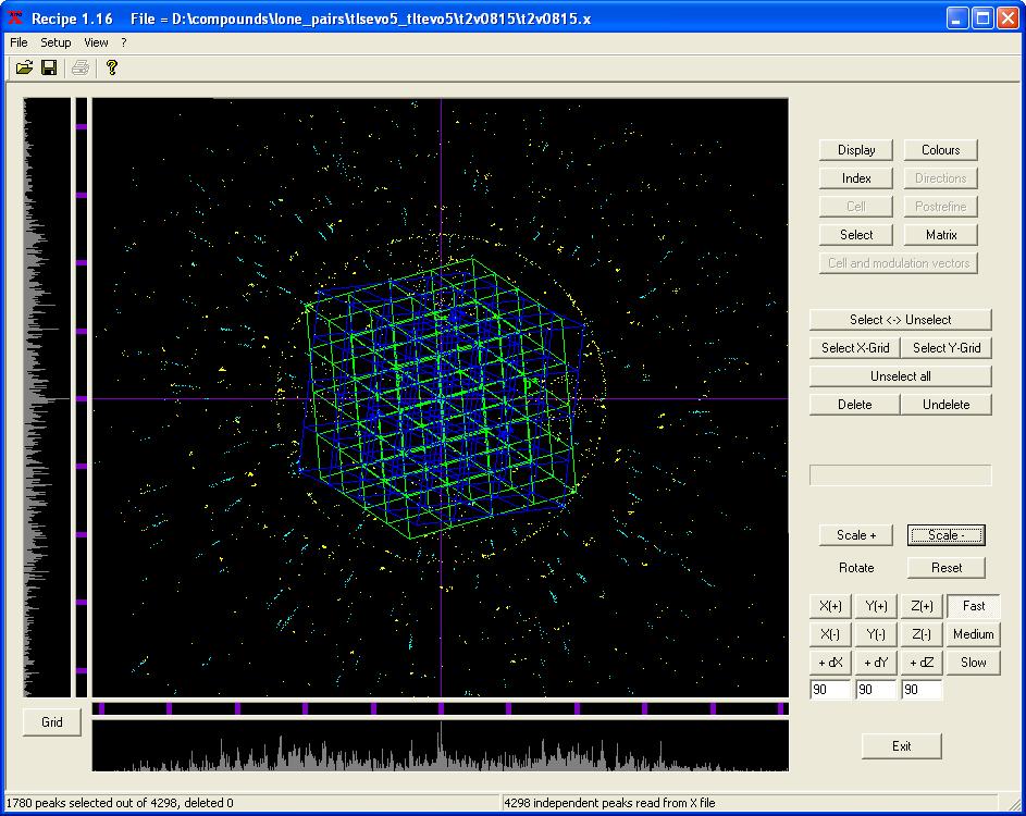
5 Peak search Indexing in reciprocal space

6 Using the currently selected peaks all difference vectors between all peak positions are calculated, normalised, and projected onto the horizontal plane of the Ewald sphere. When the crystal is a true single crystal, a series of sharp lines can be seen. Each pixel represents a direction in the reciprocal space. The picture is colour coded, the brighter the pixel the larger the frequency of difference vectors in that direction. Each line corresponds to a set of parallel, equally spaced layers in the reciprocal space. In the case of the high-pressure data, the lines from the crystal, two diamonds, and grainy spots of the gasket rings are superimposed.
7 The diamond orientation matrices are useful to check the alignment. They could be used for any other measurements in the same DAC. Hence, it is enough to find them once. Two diamond matrices cf, a 7.1 Å A contamination by the "half-wavelength" component of the Mo spectrum from a tube Diamond l/2 reflections both in a crystal-monochromated beam and in a filtered beam.
8 Twins
9
10 Shading masks

11 Masking the shaded areas of the detector (each frame has its own mask) The masks could be re-used for any other data collected in the same DAC. Hence, it is enough to determine them once. The strong diamond reflections could be masked this way.
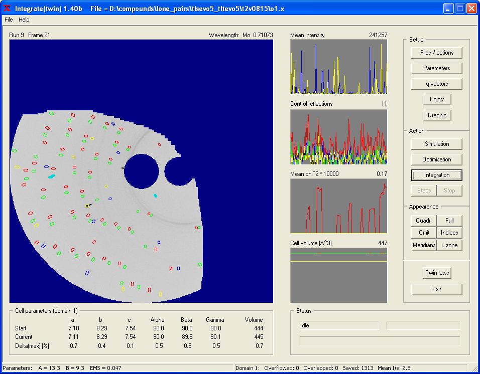
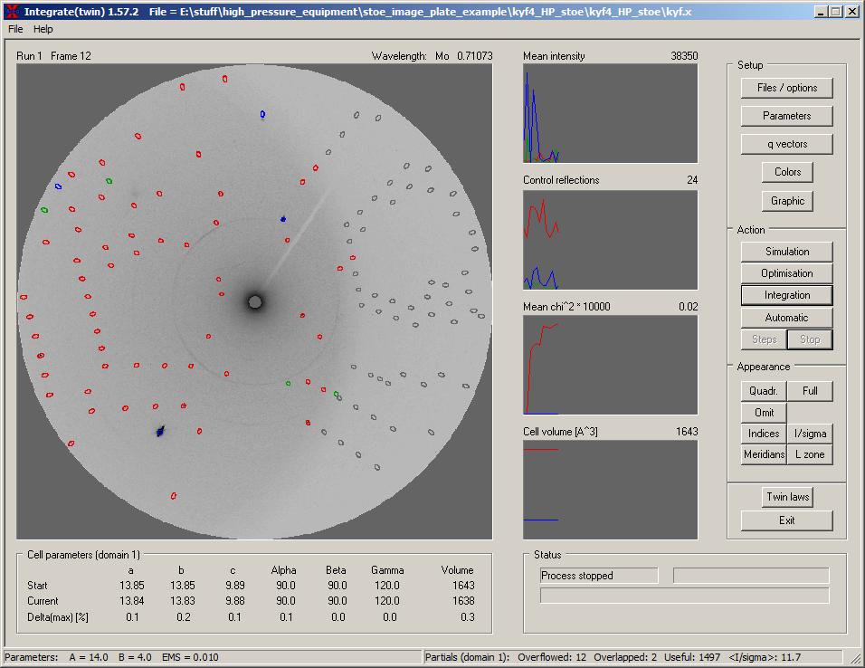
12 Integration

13 Shading cone instead of masks

14 The coordinate system uvw is centered on the goniomter: the vector v is directing upwards vertically, w is directing to the centre of the collimator, and u is oriented in a way that a righthanded Cartesian coordinate system is built. The cone is defined by the vector relating the position of the DAC with respect to the direct beam and the opening angle. When the DAC is perpendicular to the beam at = 0, j = 0, and = 0, the vector is (1 0 0). For j = 90, it is (-1 1 0). The reflections marked in grey on the following picture are the ones that are outside of the cone.
15
 + Δλ/λ tanθ (oblique incidence at higher 2θ angles and a1-a2 splitting).")
16 Integration masks Elliptical masks are used to integrate peak and background intensities. For each mask the smallest diameter is given by W = A + B tanθ, the largest diameter is defined by W / cos(2θ) + Δλ/λ tanθ (oblique incidence at higher 2θ angles and a1-a2 splitting). For obtaining the peak intensity the inner area of the mask is used. For determining the background, the pixels at the border of the ellipse are taken. EMS means effective mosaic spread and combines the divergence of the primary beam with the mosaic spread of a crystal. For a given instrument setup (the X-ray source, monochromator, and collimator) the beam divergence is constant. However the mosaic spread varies from crystal to crystal, so that EMS should be determined for each measured crystal. EMS determines how long a reflection is in the reflecting position when it passes through the surface of the Ewald sphere. The default parameters are A = 14, B = 4, and EMS = 0.01

17 Automatic optimization of A, B, and EMS: multiple frames 3-7 It is a very tricky procedure in the case of large overlap of crystal reflections with diamond reflections and gasket rings. You can t use it without having a proper cone or masks for shaded areas of the detector. You should never fully trust what this procedure gives you. Visual inspection of the results is imperative.

18 Automatic optimization of A, B, and EMS: searching for the lowest R int It is a very tricky procedure in the case of large overlap of crystal reflections with diamond reflections and gasket rings. You can t use it without having a proper cone or masks for shaded areas of the detector. You should never fully trust what this procedure gives you. Visual inspection of the results is imperative.

19 Simulation of the integration masks Usually the A, B, and EMS parameters for a good crystal of an inorganic solid in a DAC hardly ever are larger than 20, 6, and 0.04, respectively. If any of these parameters is bigger, there must be something wrong with your measurement and/or crystal.
20 Postrefine refinements of the orientation matrices of the crystal and two diamonds after integration


21 Each reflection could be inspected on the frames in the case you have doubts about its intensity during data reduction and analysis.


22 Building and viewing reciprocal space Reconstruction of reciprocal space on the basis of the measured frames
23 Twinning at high pressures in the reciprocal space
24 Some parts of the text and one figure were taken from the X- Area manual written by STOE. It is worth spending some time on reading it carefully. X-area is not a black-box software and requires conscious actions from the user.
Collect and Reduce Intensity Data Photon II
 Collect and Reduce Intensity Data Photon II General Steps in Collecting Intensity Data Note that the steps outlined below are generally followed when using all modern automated diffractometers, regardless
Diffraction I - Geometry. Chapter 3
 Diffraction I - Geometry Chapter 3 Outline ❽ Diffraction basics ❽ Braggs law ❽ Laue equations ❽ Reciprocal space and diffraction ❽ Units for x-ray wavelengths ❽ Diffraction methods Laue photographs Rotation
Crystal Quality Analysis Group
 Crystal Quality Analysis Group Contents Contents 1. Overview...1 2. Measurement principles...3 2.1 Considerations related to orientation and diffraction conditions... 3 2.2 Rocking curve measurement...
X-ray Diffraction from Materials
 X-ray Diffraction from Materials 2008 Spring Semester Lecturer; Yang Mo Koo Monday and Wednesday 14:45~16:00 8. Experimental X-ray Diffraction Procedures 8.1 Diffraction Experiments using Films 8.1.1 Laue
Collect and Reduce Intensity Data -- APEX
 Collect and Reduce Intensity Data -- APEX General Steps in Collecting Intensity Data Note that the steps outlined below are generally followed when using all modern automated diffractometers, regardless
X-ray Powder Diffraction
 X-ray Powder Diffraction Chemistry 754 Solid State Chemistry Lecture #8 April 15, 2004 Single Crystal Diffraction Diffracted Beam Incident Beam Powder Diffraction Diffracted Beam Incident Beam In powder
Winmeen Tnpsc Group 1 & 2 Self Preparation Course Physics UNIT 9. Ray Optics. surface at the point of incidence, all lie in the same plane.
 Laws of reflection Physics UNIT 9 Ray Optics The incident ray, the reflected ray and the normal drawn to the reflecting surface at the point of incidence, all lie in the same plane. The angle of incidence
Figure 1: Derivation of Bragg s Law
 What is Bragg s Law and why is it Important? Bragg s law refers to a simple equation derived by English physicists Sir W. H. Bragg and his son Sir W. L. Bragg in 1913. This equation explains why the faces
Chapter 38. Diffraction Patterns and Polarization
 Chapter 38 Diffraction Patterns and Polarization Diffraction Light of wavelength comparable to or larger than the width of a slit spreads out in all forward directions upon passing through the slit This
DETERMINATION OF THE ORIENTATION OF AN EPITAXIAL THIN FILM BY A NEW COMPUTER PROGRAM CrystalGuide
 The Rigaku Journal Vol. 16/ number 1/ 1999 Technical Note DETERMINATION OF THE ORIENTATION OF AN EPITAXIAL THIN FILM BY A NEW COMPUTER PROGRAM CrystalGuide R. YOKOYAMA AND J. HARADA X-Ray Research Laboratory,
IB-2 Polarization Practice
 Name: 1. Plane-polarized light is incident normally on a polarizer which is able to rotate in the plane perpendicular to the light as shown below. In diagram 1, the intensity of the incident light is 8
Spectrographs. C. A. Griffith, Class Notes, PTYS 521, 2016 Not for distribution.
 Spectrographs C A Griffith, Class Notes, PTYS 521, 2016 Not for distribution 1 Spectrographs and their characteristics A spectrograph is an instrument that disperses light into a frequency spectrum, which
Cover Page. The handle holds various files of this Leiden University dissertation
 Cover Page The handle http://hdl.handle.net/1887/48877 holds various files of this Leiden University dissertation Author: Li, Y. Title: A new method to reconstruct the structure from crystal images Issue
No Brain Too Small PHYSICS
 Level 3 Physics: Demonstrate understanding of Waves Waves Behaviour - Answers In 203, AS 9523 replaced AS 90520. The Mess that is NCEA Assessment Schedules. In AS 90520 there was an Evidence column with
1
 In the following tutorial we will determine by fitting the standard instrumental broadening supposing that the LaB 6 NIST powder sample broadening is negligible. This can be achieved in the MAUD program
X-Ray Diffraction Edited 10/6/15 by Stephen Albright & DGH & JS
 X-Ray Diffraction Edited 10/6/15 by Stephen Albright & DGH & JS Introduction and concepts The experiment consists of two parts. The first is to identify an unknown sample using the powder method; the second
CCP4-BGU workshop 2018 The X-ray Diffraction Experiment Diffraction Geometry and Data Collection Strategy. Andrew GW Leslie, MRC LMB, Cambridge, UK
 CCP4-BGU workshop 2018 The X-ray Diffraction Experiment Diffraction Geometry and Data Collection Strategy Andrew GW Leslie, MRC LMB, Cambridge, UK Definition of a crystal and the unit cell Crystal: An
No Brain Too Small PHYSICS
 Level 3 Physics: Demonstrate understanding of Waves Waves Behaviour - Answers In 03, AS 953 replaced AS 9050. The Mess that is NCEA Assessment Schedules. In AS 9050 there was an Evidence column with the
18th World Conference on Nondestructive Testing, April 2012, Durban, South Africa
 18th World Conference on Nondestructive Testing, 16-20 April 2012, Durban, South Africa TOWARDS ESTABLISHMENT OF STANDARDIZED PRACTICE FOR ASSESSMENT OF SPATIAL RESOLUTION AND CONTRAST OF INTERNATIONAL
Data integration and scaling
 Data integration and scaling Harry Powell MRC Laboratory of Molecular Biology 3rd February 2009 Abstract Processing diffraction images involves three basic steps, which are indexing the images, refinement
3. Image formation, Fourier analysis and CTF theory. Paula da Fonseca
 3. Image formation, Fourier analysis and CTF theory Paula da Fonseca EM course 2017 - Agenda - Overview of: Introduction to Fourier analysis o o o o Sine waves Fourier transform (simple examples of 1D
Optics Vac Work MT 2008
 Optics Vac Work MT 2008 1. Explain what is meant by the Fraunhofer condition for diffraction. [4] An aperture lies in the plane z = 0 and has amplitude transmission function T(y) independent of x. It is
BCH 6744C: Macromolecular Structure Determination by X-ray Crystallography. Practical 3 Data Processing and Reduction
 BCH 6744C: Macromolecular Structure Determination by X-ray Crystallography Practical 3 Data Processing and Reduction Introduction The X-ray diffraction images obtain in last week s practical (P2) is the
PETS process electron tilt series: a brief tutorial
 PETS process electron tilt series: a brief tutorial 1. Introduction PETS is a program for processing a series of diffraction images. It is intended for electron diffraction. In principle it could be used
Grazing Angle 2 Theta Phase Analysis
 Page 1 of 7 Grazing Angle 2 Theta Phase Analysis 1. Log into the User Log System on the SMIF web site Hardware Setup X-Ray Tube The line focus configuration of the x-ray tube is used. This is the default
proteindiffraction.org Select
 This tutorial will walk you through the steps of processing the data from an X-ray diffraction experiment using HKL-2000. If you need to install HKL-2000, please see the instructions at the HKL Research
What is it? How does it work? How do we use it?
 What is it? How does it work? How do we use it? Dual Nature http://www.youtube.com/watch?v=dfpeprq7ogc o Electromagnetic Waves display wave behavior o Created by oscillating electric and magnetic fields
Rietveld refinements collection strategies!
 Rietveld refinements collection strategies! Luca Lutterotti! Department of Materials Engineering and Industrial Technologies! University of Trento - Italy! Quality of the experiment! A good refinement,
Lecture 4 Recap of PHYS110-1 lecture Physical Optics - 4 lectures EM spectrum and colour Light sources Interference and diffraction Polarization
 Lecture 4 Recap of PHYS110-1 lecture Physical Optics - 4 lectures EM spectrum and colour Light sources Interference and diffraction Polarization Lens Aberrations - 3 lectures Spherical aberrations Coma,
Chapter 24. Wave Optics
 Chapter 24 Wave Optics Diffraction Huygen s principle requires that the waves spread out after they pass through slits This spreading out of light from its initial line of travel is called diffraction
NEW POSSIBILITIES FOR X-RAY DIFFRACTOMETRY. Bernd Hasse Incoatec, Geesthacht, Germany
 NEW POSSIBILITIES FOR X-RAY DIFFRACTOMETRY Bernd Hasse Incoatec, Geesthacht, Germany This document was presented at PPXRD - Pharmaceutical Powder X-ray Diffraction Symposium Sponsored by The International
COMPARISON BETWEEN CONVENTIONAL AND TWO-DIMENSIONAL XRD
 Copyright JCPDS - International Centre for Diffraction Data 2003, Advances in X-ray Analysis, Volume 46. 37 COMPARISON BETWEEN CONVENTIONAL AND TWO-DIMENSIONAL XRD Bob B. He, Uwe Preckwinkel, and Kingsley
Mirrors. N.G. Schultheiss translated and adapted by K. Schadenberg
 Mirrors N.G. Schultheiss translated and adapted by K. Schadenberg 1 Introduction This module Mirrors summarizes and extents your basic knowledge about mirrors. After this module you can proceed with the
Diffraction geometry and integration of diffraction images
 Diffraction geometry and integration of diffraction images Phil Evans Okinawa December 2011 MRC Laboratory of Molecular Biology Cambridge UK Integration h k l I σ(i)... Image series Reflection intensity
Characterizing x-ray mirrors in reciprocal space
 Characterizing x-ray mirrors in reciprocal space Preliminary results from the NIST X-ray Optics Evaluation Double-Crystal Diffractometer D.L. Gil, D. Windover, J.P. Cline, A. Henins National Institute
ANOMALOUS SCATTERING FROM SINGLE CRYSTAL SUBSTRATE
 177 ANOMALOUS SCATTERING FROM SINGLE CRYSTAL SUBSTRATE L. K. Bekessy, N. A. Raftery, and S. Russell Faculty of Science, Queensland University of Technology, GPO Box 2434, Brisbane, Queensland, Australia
Maintenance Package Measurement
 Maintenance Package Measurement Contents Contents 1. Package measurement flow...1 2. Measurement procedures...3 2.1 Startup... 3 2.2 Hardware setup... 4 2.3 Setting Package measurement conditions... 7
MICHELSON S INTERFEROMETER
 MICHELSON S INTERFEROMETER Objectives: 1. Alignment of Michelson s Interferometer using He-Ne laser to observe concentric circular fringes 2. Measurement of the wavelength of He-Ne Laser and Na lamp using
Reflective Illumination for DMS 803 / 505
 APPLICATION NOTE // Dr. Michael E. Becker Reflective Illumination for DMS 803 / 505 DHS, SDR, VADIS, PID & PLS The instruments of the DMS 803 / 505 series are precision goniometers for directional scanning
PY106 Class31. Index of refraction. Refraction. Index of refraction. Sample values of n. Rays and wavefronts. index of refraction: n v.
 Refraction Index of refraction When an EM wave travels in a vacuum, its speed is: c = 3.00 x 10 8 m/s. In any other medium, light generally travels at a slower speed. The speed of light v in a material
Chapter 36. Diffraction. Dr. Armen Kocharian
 Chapter 36 Diffraction Dr. Armen Kocharian Diffraction Light of wavelength comparable to or larger than the width of a slit spreads out in all forward directions upon passing through the slit This phenomena
Basic and Intermediate Math Vocabulary Spring 2017 Semester
 Digit A symbol for a number (1-9) Whole Number A number without fractions or decimals. Place Value The value of a digit that depends on the position in the number. Even number A natural number that is
Advanced Crystal Structure Analysis Using XDS with Small Molecule Data. Tim Grüne Georg-August-Universität Institut für Strukturchemie
 Advanced Crystal Structure Analysis Using XDS with Small Molecule Data Tim Grüne Georg-August-Universität Institut für Strukturchemie tt s 1 7t tg@shelx.uni-ac.gwdg.de November 13, 2013 Tim Grüne XDS:
Devices displaying 3D image. RNDr. Róbert Bohdal, PhD.
 Devices displaying 3D image RNDr. Róbert Bohdal, PhD. 1 Types of devices displaying 3D image Stereoscopic Re-imaging Volumetric Autostereoscopic Holograms mounted displays, optical head-worn displays Pseudo
CrysAlis Pro Proteins, Large Unit Cells and Difficult Data Sets
 CrysAlis Pro Proteins, Large Unit Cells and Difficult Data Sets Tadeusz Skarzynski Agilent Technologies UK Mathias Meyer Agilent Technologies Poland Oliver Presly Agilent Technologies UK Seminar Layout
diffraction patterns obtained with convergent electron beams yield more information than patterns obtained with parallel electron beams:
 CBED-Patterns Principle of CBED diffraction patterns obtained with convergent electron beams yield more information than patterns obtained with parallel electron beams: specimen thickness more precise
ENGR142 PHYS 115 Geometrical Optics and Lenses
 ENGR142 PHYS 115 Geometrical Optics and Lenses Part A: Rays of Light Part B: Lenses: Objects, Images, Aberration References Pre-lab reading Serway and Jewett, Chapters 35 and 36. Introduction Optics play
Diffraction. Single-slit diffraction. Diffraction by a circular aperture. Chapter 38. In the forward direction, the intensity is maximal.
 Diffraction Chapter 38 Huygens construction may be used to find the wave observed on the downstream side of an aperture of any shape. Diffraction The interference pattern encodes the shape as a Fourier
Dispersion (23.5) Neil Alberding (SFU Physics) Physics 121: Optics, Electricity & Magnetism Spring / 17
 Neil Alberding (SFU Physics) Physics 121: Optics, Electricity & Magnetism Spring / 17") Neil Alberding (SFU Physics) Physics 121: Optics, Electricity & Magnetism Spring 2010 1 / 17 Dispersion (23.5) The speed of light in a material depends on its wavelength White light is a mixture of wavelengths
Neil Alberding (SFU Physics) Physics 121: Optics, Electricity & Magnetism Spring 2010 1 / 17 Dispersion (23.5) The speed of light in a material depends on its wavelength White light is a mixture of wavelengths
1. Polarization effects in optical spectra of photonic crystals
 Speech for JASS 05. April 2005. Samusev A. 1. Polarization effects in optical spectra of photonic crystals Good afternoon. I would like to introduce myself. My name is Anton Samusev. I m a student of Saint
Panalytical MRD X-Ray Diffraction SOP
 Panalytical MRD X-Ray Diffraction SOP Table of Contents 1.0 Safety 2.0 Training 3.0 Sample Preparation 4.0 Pre-Operation 5.0 Sample Height Adjustment 6.0 Running Programs 7.0 Sample Unloading 8.0 Post-Operation
FINDING THE INDEX OF REFRACTION - WebAssign
 Name: Book: Period: Due Date: Lab Partners: FINDING THE INDEX OF REFRACTION - WebAssign Purpose: The theme in this lab is the interaction between light and matter. Matter and light seem very different
11.1 CHARACTERISTICS OF LIGHT
 CHARACTERISTICS OF LIGHT 11.1 An electromagnetic wave has both electric and magnetic parts; it does not require a medium, and it travels at the speed of light. As wavelength decreases, energy increases.
Display system analysis with critical polarization elements in a nonsequential ray tracing environment
 Copyright 2008, Society of Photo-Optical Instrumentation Engineers (SPIE). This paper was published in the proceedings of the August 2008 SPIE Annual Meeting and is made available as an electronic reprint
Scattering/Wave Terminology A few terms show up throughout the discussion of electron microscopy:
 1. Scattering and Diffraction Scattering/Wave Terology A few terms show up throughout the discussion of electron microscopy: First, what do we mean by the terms elastic and inelastic? These are both related
Physics 1CL WAVE OPTICS: INTERFERENCE AND DIFFRACTION Fall 2009
 Introduction An important property of waves is interference. You are familiar with some simple examples of interference of sound waves. This interference effect produces positions having large amplitude
College Physics 150. Chapter 25 Interference and Diffraction
 College Physics 50 Chapter 5 Interference and Diffraction Constructive and Destructive Interference The Michelson Interferometer Thin Films Young s Double Slit Experiment Gratings Diffraction Resolution
Chap. 4. Jones Matrix Method
 Chap. 4. Jones Matrix Method 4.1. Jones Matrix Formulation - For an incident light with a polarization state described by the Jones vector - Decompose the light into a linear combination of the "fast"
Stress and Texture by XRD Bob He, Bruker AXS
 Stress and Texture by XRD Bob He, Bruker AXS Intensity Conventional X-ray Diffractometer Divergence slit Antiscatter slit Monochromator Bragg-Brentano Geometry. Scanning over range to collect XRD pattern.
Bragg Diffraction from 2-D Nanoparticle Arrays adapted by Preston Snee and Ali Jawaid
 ADH 9/9/2013 I. Introduction Bragg Diffraction from 2-D Nanoparticle Arrays adapted by Preston Snee and Ali Jawaid In this module, we will investigate how a crystal lattice of nanoparticles can act as
Chapter 36. Diffraction. Copyright 2014 John Wiley & Sons, Inc. All rights reserved.
 Chapter 36 Diffraction Copyright 36-1 Single-Slit Diffraction Learning Objectives 36.01 Describe the diffraction of light waves by a narrow opening and an edge, and also describe the resulting interference
Applications of Piezo Actuators for Space Instrument Optical Alignment
 Year 4 University of Birmingham Presentation Applications of Piezo Actuators for Space Instrument Optical Alignment Michelle Louise Antonik 520689 Supervisor: Prof. B. Swinyard Outline of Presentation
UNIT 102-9: INTERFERENCE AND DIFFRACTION
 Name St.No. - Date(YY/MM/DD) / / Section Group # UNIT 102-9: INTERFERENCE AND DIFFRACTION Patterns created by interference of light in a thin film. OBJECTIVES 1. Understand the creation of double-slit
CONTENTS Huygens Theory of Double Refraction Principal Working Nicol Prism as a Polariser and an Analyser Quarter Wave Plate Half Wave Plate
 CONTENTS Huygens Theory of Double Refraction Principal Construction Working Nicol Prism as a Polariser and an Analyser Quarter Wave Plate Half Wave Plate POLARISATION Huygens Theory of Double Refraction
specular diffuse reflection.
 Lesson 8 Light and Optics The Nature of Light Properties of Light: Reflection Refraction Interference Diffraction Polarization Dispersion and Prisms Total Internal Reflection Huygens s Principle The Nature
POLARIZATION 3.5 RETARDATION PLATES
 Nicol Prism as Polarizer and Analyzer: Nicol prism can be used both as polarizer and as an analyzer. When two Nicol prisms are mounted co axially, then the first Nicol prism N 1 which produces plane polarized
9. Polarization. 1) General observations [Room 310]
![9. Polarization. 1) General observations [Room 310]](/thumbs/74/70594885.jpg "9. Polarization. 1) General observations [Room 310]") 9. Polarization In this lab we are going to study the various phenomena related to the polarization of light. We will also learn how to analyze, control and transfer the polarization state of light. This
9. Polarization In this lab we are going to study the various phenomena related to the polarization of light. We will also learn how to analyze, control and transfer the polarization state of light. This
Light Tec Scattering measurements guideline
 Light Tec Scattering measurements guideline 1 2 Light Tec Locations REFLET assembling plant, Aix-en-Provence, France Light Tec GmbH, Munich, Germany German office Light Tec Sarl, Hyères, France Main office
Chapter 35 &36 Physical Optics
 Chapter 35 &36 Physical Optics Physical Optics Phase Difference & Coherence Thin Film Interference 2-Slit Interference Single Slit Interference Diffraction Patterns Diffraction Grating Diffraction & Resolution
Chapter 24. Wave Optics
 Chapter 24 Wave Optics Wave Optics The wave nature of light is needed to explain various phenomena Interference Diffraction Polarization The particle nature of light was the basis for ray (geometric) optics
Mu lt i s p e c t r a l
 Viewing Angle Analyser Revolutionary system for full spectral and polarization measurement in the entire viewing angle EZContrastMS80 & EZContrastMS88 ADVANCED LIGHT ANALYSIS by Field iris Fourier plane
Fast, Intuitive Structure Determination II: Crystal Indexing and Data Collection Strategy. April 2,
 Fast, Intuitive Structure Determination II: Crystal Indexing and Data Collection Strategy April 2, 2013 1 Welcome I I Dr. Michael Ruf Product Manager Crystallography Bruker AXS Inc. Madison, WI, USA Bruce
Michelson Interferometer
 Michelson Interferometer The Michelson interferometer uses the interference of two reflected waves The third, beamsplitting, mirror is partially reflecting ( half silvered, except it s a thin Aluminum
THE INFLUENCE OF SURFACE ROUGHNESS ON THE REFRACTION OF X-RAYS AND ITS EFFECT ON BRAGG PEAK POSITIONS
 Copyright JCPDS - International Centre for Diffraction Data 2003, Advances in X-ray Analysis, Volume 46. 232 THE INFLUENCE OF SURFACE ROUGHNESS ON THE REFRACTION OF X-RAYS AND ITS EFFECT ON BRAGG PEAK
All forms of EM waves travel at the speed of light in a vacuum = 3.00 x 10 8 m/s This speed is constant in air as well
 Pre AP Physics Light & Optics Chapters 14-16 Light is an electromagnetic wave Electromagnetic waves: Oscillating electric and magnetic fields that are perpendicular to the direction the wave moves Difference
4. Recommended alignment procedure:
 4. Recommended alignment procedure: 4.1 Introduction The described below procedure presents an example of alignment of beam shapers Shaper and Focal- Shaper (F- Shaper) with using the standard Shaper Mount
Validation of aspects of BeamTool
 Vol.19 No.05 (May 2014) - The e-journal of Nondestructive Testing - ISSN 1435-4934 www.ndt.net/?id=15673 Validation of aspects of BeamTool E. GINZEL 1, M. MATHESON 2, P. CYR 2, B. BROWN 2 1 Materials Research
Original grey level r Fig.1
 Point Processing: In point processing, we work with single pixels i.e. T is 1 x 1 operator. It means that the new value f(x, y) depends on the operator T and the present f(x, y). Some of the common examples
Light Tec Scattering measurements guideline
 Light Tec Scattering measurements guideline 1 Our Laboratory Light Tec is equipped with a Photometric Laboratory (a dark room) including: Goniophotometers: REFLET 180S. High specular bench (10 meters),
X-ray thin-film measurement techniques
 X-ray thin-film measurement techniques VIII. Detectors and series summary Shintaro Kobayashi* and Katsuhiko Inaba* 1. Introduction The various XRD techniques as the characterization tools for thin film
Using a multipoint interferometer to measure the orbital angular momentum of light
 CHAPTER 3 Using a multipoint interferometer to measure the orbital angular momentum of light Recently it was shown that the orbital angular momentum of light can be measured using a multipoint interferometer,
4. A bulb has a luminous flux of 2400 lm. What is the luminous intensity of the bulb?
 1. Match the physical quantities (first column) with the units (second column). 4. A bulb has a luminous flux of 2400 lm. What is the luminous intensity of the bulb? (π=3.) Luminous flux A. candela Radiant
Unit 5.A Properties of Light Essential Fundamentals of Light 1. Electromagnetic radiation has oscillating magnetic and electric components.
 Unit 5.A Properties of Light Essential Fundamentals of Light 1. Electromagnetic radiation has oscillating magnetic and electric components. Early Booklet E.C.: + 1 Unit 5.A Hwk. Pts.: / 18 Unit 5.A Lab
Properties of Light. 1. The Speed of Light 2. The Propagation of Light 3. Reflection and Refraction 4. Polarization
 Chapter 33 - Light Properties of Light 1. The Speed of Light 2. The Propagation of Light 3. Reflection and Refraction 4. Polarization MFMcGraw-PHY 2426 Chap33-Light - Revised: 6-24-2012 2 Electromagnetic
Second Year Optics 2017 Problem Set 1
 Second Year Optics 2017 Problem Set 1 Q1 (Revision of first year material): Two long slits of negligible width, separated by a distance d are illuminated by monochromatic light of wavelength λ from a point
STEP-BY-STEP INSTRUCTIONS FOR BUILDING A FLUORESCENCE MICROSCOPE. TECHSPEC Optical Cage System
 STEP-BY-STEP INSTRUCTIONS FOR BUILDING A FLUORESCENCE MICROSCOPE TECHSPEC Optical Cage System INTRODUCTION 2 What is a Digital Fluorescence Microscope? Unlike traditional microscopes, which utilize an
A 4. An electromagnetic wave travelling through a transparent medium is given by y. in S units. Then what is the refractive index of the medium?
 SECTION (A) : PRINCIPLE OF SUPERPOSITION, PATH DIFFERENCE, WAVEFRONTS, AND COHERENCE A 1. Two sources of intensity I & 4I are used in an interference experiment. Find the intensity at points where the
Experiment 5: Polarization and Interference
 Experiment 5: Polarization and Interference Nate Saffold nas2173@columbia.edu Office Hour: Mondays, 5:30PM-6:30PM @ Pupin 1216 INTRO TO EXPERIMENTAL PHYS-LAB 1493/1494/2699 Introduction Outline: Review
(Equation 24.1: Index of refraction) We can make sense of what happens in Figure 24.1
 We can make sense of what happens in Figure 24.1") 24-1 Refraction To understand what happens when light passes from one medium to another, we again use a model that involves rays and wave fronts, as we did with reflection. Let s begin by creating a short
24-1 Refraction To understand what happens when light passes from one medium to another, we again use a model that involves rays and wave fronts, as we did with reflection. Let s begin by creating a short
Supplementary Figure 1 Optimum transmissive mask design for shaping an incident light to a desired
 Supplementary Figure 1 Optimum transmissive mask design for shaping an incident light to a desired tangential form. (a) The light from the sources and scatterers in the half space (1) passes through the
READ THIS FIRST Read the text carefully - most questions that you are likely to have are addressed in this document. (1) Introduction to imosflm
 Introduction to imosflm") imosflm introductory & intermediate lessons READ THIS FIRST Read the text carefully - most questions that you are likely to have are addressed in this document. If you have not used imosflm before, or
imosflm introductory & intermediate lessons READ THIS FIRST Read the text carefully - most questions that you are likely to have are addressed in this document. If you have not used imosflm before, or
Physics 1C, Summer 2011 (Session 1) Practice Midterm 2 (50+4 points) Solutions
 Practice Midterm 2 (50+4 points) Solutions") Physics 1C, Summer 2011 (Session 1) Practice Midterm 2 (50+4 points) s Problem 1 (5x2 = 10 points) Label the following statements as True or False, with a one- or two-sentence explanation for why you chose
Physics 1C, Summer 2011 (Session 1) Practice Midterm 2 (50+4 points) s Problem 1 (5x2 = 10 points) Label the following statements as True or False, with a one- or two-sentence explanation for why you chose
Image Formation by Refraction
 Image Formation by Refraction If you see a fish that appears to be swimming close to the front window of the aquarium, but then look through the side of the aquarium, you ll find that the fish is actually
Optics: Reflection and Refraction (approx. completion time: 2.5 h) (3/28/11)
 (3/28/11)") Optics: Reflection and Refraction (approx. completion time: 2.5 h) (3/28/11) Introduction In this lab you will investigate the reflection and refraction of light. Reflection of light from a surface is
Optics: Reflection and Refraction (approx. completion time: 2.5 h) (3/28/11) Introduction In this lab you will investigate the reflection and refraction of light. Reflection of light from a surface is
ECEN 4606, UNDERGRADUATE OPTICS LAB
 ECEN 4606, UNDERGRADUATE OPTICS LAB Lab 5: Interferometry and Coherence SUMMARY: In this lab you will use interference of a temporally coherent (very narrow temporal frequency bandwidth) laser beam to
Light Tec Scattering measurements guideline
 Light Tec Scattering measurements guideline 1 Our Laboratory Light Tec is equipped with a Photometric Laboratory (a dark room) including: Goniophotometers: REFLET 180S. High specular bench (10 meters),
25-1 Interference from Two Sources
 25-1 Interference from Two Sources In this chapter, our focus will be on the wave behavior of light, and on how two or more light waves interfere. However, the same concepts apply to sound waves, and other
LUSI SUB-SYSTEM XCS Physics Requirements for the LUSI Large Offset Monochromator. Doc. No. SP R0
 PHYSICS REQUIREMENT DOCUMENT (PRD) Doc. No. SP-391-00-16 R0 LUSI SUB-SYSTEM XCS Physics Requirements for the Aymeric Robert Author, LUSI Scientist Signature Date David Fritz LUSI Scientist Signature Date
The image is virtual and erect. When a mirror is rotated through a certain angle, the reflected ray is rotated through twice this angle.
 1 Class XII: Physics Chapter 9: Ray optics and Optical Instruments Top Concepts 1. Laws of Reflection. The reflection at a plane surface always takes place in accordance with the following two laws: (i)
Data Processing with XDS
 WIR SCHAFFEN WISSEN HEUTE FÜR MORGEN Dr. Tim Grüne :: Paul Scherrer Institut :: tim.gruene@psi.ch Data Processing with XDS CCP4 / APS School Chicago 2017 19 th June 2017 1 - X-ray Diffraction in a Nutshell