EXPERIMENT NO: NAME OF EXPERIMENT: -01 2D & 3D CAD modelling methodology using package AutoCAD.
|
|
|
- Justina Singleton
- 5 years ago
- Views:
Transcription
1 SHRI SHIVAJI EDUCATION SOCIETY, AMRAVATI S, COLLEGE OF ENGINEERING & TECHNOLOGY, AKOLA Babhulgaon (JH) N.H.No.6, Akola DEPARTMENT OF MECHANICAL ENGINEERING COMPUTER SOFTWARE APPLICATIONS -I LAB. (5ME10) EXPERIMENT NO: - 01 NAME OF EXPERIMENT: -01 2D & 3D CAD modelling methodology using package AutoCAD. INTRODUCTION:- AutoCAD is a CAD software application for 2D and 3D design and drafting. It is developed and sold by Autodesk, Inc. first released in December 1982; AutoCAD was one of the first CAD programs to run on personal computers, notably the IBM PC. At that time, most other CAD programs ran on mainframe computers or mini-computers that were connected to a graphics computer terminal for each user. The term CAD (Computer Aided Design) applies to a wide range of programs that allow th user to created drawings, plans, and designs electronically. AutoCAD is one such program and it main claim to fame is that it is relatively easy to use, it is very comprehensive in its ability to create 2D and some 3D drawings, and it is very popular. Seventy percent of the CAD users in the world use AutoCAD.

2 COMMANDS USED IN AUTO CAD 1) Extend Command: The Extend command is use to lengthen drawn lines to meet the edges of other objects. When you use Extend command, you select lines as boundary edges and extend other lines to those edges. Procedures: 1- Select EXTEND from: - Modify Tool bar - Pull-Down menu - Type Extend at the command line. 2- Select boundary edges then press enter. 3- Select edge to extend then press enter to terminate the command. Example:
3 2) Trim Command The Trim command is use to shorten drawn lines to meet the edges of other objects. Procedures: 1- Select TRIM Command from: - Modify Tool bar - Pull-Down menu - Type Trim at the command line. 2- Select cutting edge then press enter. See figure below. 3- Select object to trim then press enter. See figure below. Example:
4 3) Offset Command The Offset command creates new object parallel to the original object at specified distance and direction. Procedures: 1- Select the Offset Command from: - Modify Tool bar - Pull-Down menu - Type Offset at the command line. 2- At Specify offset distance or [through]: Enter a value or pick a point on the screen. 3- At Select object to offset or <exit>: select the object. 4- At specify point on side to offset: pick a point on the screen you want to place the new object. 4) COPY Command In AutoCAD you can use Copy command to create duplicates of objects at different locations from the original. Procedures: 1- Select the Copy command from: - Modify Toolbar. - Modify pull-down menu -Type Copy at command line. 2- Select the object you want to copy and Enter. 3- At the "Specify the base point or displacement" Pick a point on the object. This point will serve as handle for the object.
5 4- At the "Specify second point or displacement" pick a point on the screen or enter distance. You can create multiple copies without leaving the copy command. 5) Mirror Command: The mirror command creates a mirror image of objects. Mirror command is useful for objects that present symmetry. You draw half of the object and you mirror the other half. Procedures: 1- Select Mirror command from: - Modify Tool bar - Pull-Down menu - Type Mirror at the command line. 2- Select object then press enter. 3- At Specify first point of mirror line, select P1, see figure below. 4- At Specify second point of mirror line, select P2, see figure below. 5- At Delete source object? [Yes/No] <N>. Press enter. Example:
6 6) MOVE Command: This AutoCAD command will allow you to move the original objects at specified distance in a specified direction. Procedures: - Modify Toolbar - Modify from the Pull-Down Menu\ - Type M for move at the command line and press enter. Example: 7) Erase Command: The erase command is used to delete selected objects from you drawing. Procedures: - Modify Toolbar. - Pull-down Menu. - Command line: Type erase or e then press enter. Procedure: 1- Choose one the method described above to activate Erase Command. 2- Select the object to erase then press enter.
7 8) SCALE Command: Enlarges or reduces selected objects, keeping the proportions of the object the same after scaling Procedures: 1- Select Scale command from: - Modify Toolbar. - Pull-down Menu. - Command line: Type Scale then press enter. 2- Select object then press enter. 3- Specify the base point 4- Enter Scale factor 9) ROTATE Command: Rotates objects around a base point Procedures: 1- Select Scale command from: - Modify Toolbar. - Pull-down Menu. - Command line: Type Rotate then press enter. 2- Select object then press enter. 3- Specify the base point 4- Rotate the object according base point Function and Accelerator Keys F1 Online Help F2 Flipscreen F3 Osnap ON/OFF F4 Tablet On/Off F5 Isoplane Toggle F6 Coords On/Off
8 F7 Grid On/Off F8 Ortho On/Off F9 Snap On/Off F10 Polar On/Off F11 Object Snap Tracking ON/OFF Press CTRL + A to turn GROUPS on/off. Press CTRL + B to turn SNAP on/off. Press CTRL + C to COPYCLIP Press CTRL + D to turn COORDS on/off. Press CTRL +E to Toggle Isoplane settings. Press CTRL +F to turn Osnaps ON/OFF Press CTRL + G to turn GRID on/off. Press CRTL + K for Hyperlinks Press CTRL + L to turn ORTHO ON/OFF Press CTRL + N to create a NEW drawing.* Press CTRL + O to OPEN an existing drawing.* Press CTRL + P to PLOT a drawing.* Press CTRL + S to qsave a drawing.* Press CTRL + T to turn the digitizing tablet on/off. Press CTRL + X to cut to Clipboard.* Press CTRL + Z to UNDO 2D MODELING OF FOLLOWING OBJECTS
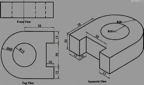
9
10 SHRI SHIVAJI EDUCATION SOCIETY, AMRAVATI S, COLLEGE OF ENGINEERING & TECHNOLOGY, AKOLA Babhulgaon (JH) N.H.No.6, Akola DEPARTMENT OF MECHANICAL ENGINEERING COMPUTER SOFTWARE APPLICATIONS -I LAB. (5ME10) EXPERIMENT NO:- 02 NAME OF EXPERIMENT: - Creation of 2D Drawing (Sketching module) of any three mechanical machine component using Pro/ENGINEER. INTRODUCTION:- Pro/ENGINEER is a parametric, integrated 3D CAD/CAM/CAE solution created by Parametric Technology Corporation (PTC). It was the first to market with parametric, feature-based, associative solid modeling software. The application runs on Microsoft Windows platforms, and provides solid modeling, assembly modeling and drafting, finite element analysis, and NC and tooling functionality for mechanical engineers. Pro/ENGINEER is a fully associative system. This means that a change in the design model anytime in the development process is propagated throughout the design, automatically updating all engineering deliverables, including assemblies, drawings, and manufacturing data. Associatively makes concurrent engineering possible by encouraging change, without penalty, at any point in the development cycle. This enables downstream functions to contribute their knowledge and expertise early in the development cycle. This software has widely used in industries for modeling purpose. Following are few basic important working notes to get acquainted with this software. Pro/E also allows operator the flexibility of using sketched and parametric based design Pro/E is the power operator expect. It is the leading edge technology starting with project concept trough design assembly tasting manufacturing and modeling to rendering capabilities.
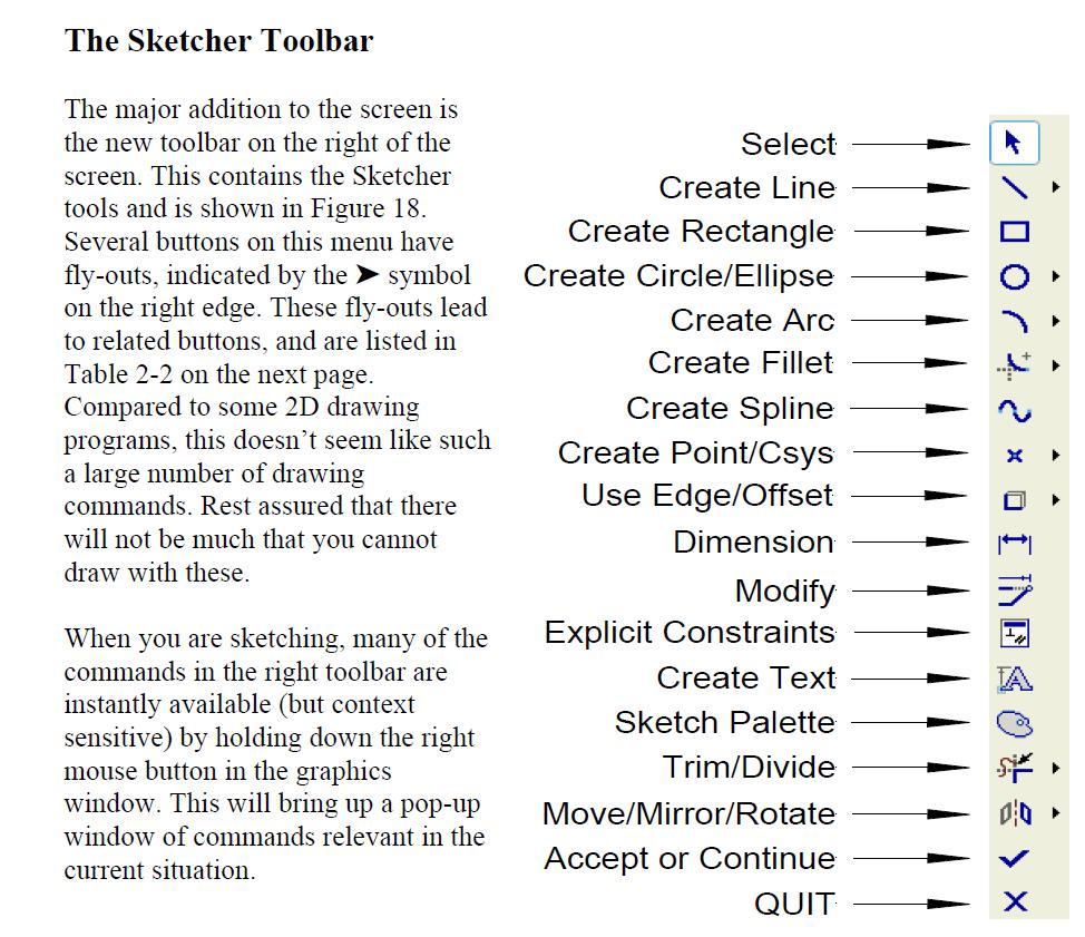
11 Introducing Sketcher Module Sketcher is the most important tool for creating features in Pro/E. It is therefore critical that you have a good understanding of how it works. We will take a few minutes here to describe its basic operation and will explore the Sketcher tools continually through the next few lessons. It will take you a lot of practice and experience to fully appreciate all that it can do. Basically, Sketcher is a tool for creating two-dimensional figures. These can be either stand-alone features (Sketched Curves) or as embedded elements that define the cross sectional shape of some solid features. The aspects of these figures that must be defined are location, shape, and size, roughly in that order. The sketching plane where we will create the 2D sketch is defined or selected first. Then, within Sketcher the location is further specified by selecting references to existing geometry. You will find the usual drawing tools for lines, arcs, circles, and so on, to create the shape. Finally, you can specify alignments or dimensions to control the size of the sketch and its relation to existing geometry. Sketcher is really quite smart, that is, it will anticipate what you are going to do (usually correctly!) and do many things automatically. Occasionally, it does make a mistake in guessing what you want. So, learning how to use Sketcher effectively involves understanding exactly what it is doing for you (and why) and discovering ways that you can easily over-ride this when necessary. The shape of the sketch but also in how constraints and dimensions are applied to the sketch so that it is both complete and conveys the important design goals for the feature. In Wildfire 4.0, some very useful new tools have been introduced in Sketcher. These make it considerably easier to diagnose errors in sketches (such as duplicated edges) or improper sketches (such as open curves for features that

12 require closed curves). We will investigate these tools by intentionally introducing some errors into our sketches.
13

14 Sketcher Toolbar Flyout Buttons 2D MODELING OF FOLLOWING OBJECT
15

16 SHRI SHIVAJI EDUCATION SOCIETY, AMRAVATI S, COLLEGE OF ENGINEERING & TECHNOLOGY, AKOLA Babhulgaon (JH) N.H.No.6, Akola DEPARTMENT OF MECHANICAL ENGINEERING COMPUTER SOFTWARE APPLICATIONS -I LAB. (5ME10) EXPERIMENT NO: - 3 NAME OF EXPERIMENT: - Creation of 3D drawing (part Module) of mechanical machine parts using Pro-E.

17 Pro/ENGINEER Feature Overview Below (and/or to the right of) the datum creation buttons in the right toolbar are three other groups of buttons. These are shown in Figures 7, 8, and 9. If you move the cursor over the buttons, the tool tip box will show the button name. Two of these menus contain buttons for creating features, organized into the following categories: Placed Features (Figure 7) - (holes, rounds, shells,...) These are features that are created directly on existing solid geometry. Examples are placing a hole on an existing surface, or creating a round on an existing edge of a part. Sketched Features (Figure 8) (extrusions, revolves, sweeps, blends,..) These features require the definition of a two-dimensional cross section which is then manipulated into the third dimension. Although they usually use existing geometry for references, they do not specifically require this. These features will involve the use of an important tool called Sketcher. The final group of buttons (Figure 9) is used for editing and modifying existing features. We will deal with some of these commands (Mirror and Pattern) later in the Tutorial. In this lesson we will be using the Extrude command to create two types of sketched features (a protrusion and a cut). In the next lesson, we will use the Hole, Round, and Chamfer commands to create three placed features. Before we continue, though, we must find out about an important tool - Sketcher.
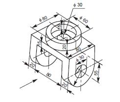
18 3D MODELING OF FOLLOWING OBJECT
19
20
21 SHRI SHIVAJI EDUCATION SOCIETY, AMRAVATI S, COLLEGE OF ENGINEERING & TECHNOLOGY, AKOLA Babhulgaon (JH) N.H.No.6, Akola DEPARTMENT OF MECHANICAL ENGINEERING COMPUTER SOFTWARE APPLICATIONS -I LAB. (5ME10) EXPERIMENT NO:-04 NAME OF EXPERIMENT: - Creation of 3D drawing (part Module) of any three mechanical machine parts using CATIA. INTRODUCTION CATIA (Computer Aided Three dimensional Interactive Application) is a multiplatform PLM/CAD/CAM/CAE commercial software suite developed by Dassault Systemes and marketed world-wide by IBM. It was used by Frank Gehry in his building of the Guggenheim Museum Bilbao. CATIA is written in the C++ programming language using the Standard Template Library. Catia V5 software solution,addresses advanced mechanical process centric design requirement.in addtion to leading edge featur-based design function,it includes highly productive capabilities for the design of mechanical assemblies and for drawing generation. catia v5 is avilable on both unix and windows enviroments. Also as an open solution,it includes interfaces with the most commonly used data exchange industry standards. Catia V5 features a parametric solid/surface-based package which uses NURBS as the core surface representation and has several workbenches that provide KBE support. 3DXML is the basis for model visualization, persistence, and distribution.as of 2007, the latest release is V5 release 17 (V5R17).One of the main reasons customers choose CATIA V5 is its ability to seamlessly interact


22 and work in tandem with a host of other applications like Enovia, Smarteam, various CAE Analysis applications etc. COMMANNDS USED

23

24 MODELING OF OBJECT
25

26 SHRI SHIVAJI EDUCATION SOCIETY, AMRAVATI S, COLLEGE OF ENGINEERING & TECHNOLOGY, AKOLA Babhulgaon (JH) N.H.No.6, Akola DEPARTMENT OF MECHANICAL ENGINEERING COMPUTER SOFTWARE APPLICATIONS -I LAB. (5ME10) EXPERIMENT NO: - 5 NAME OF EXPERIMENT: - Creation of an assembly using (assembly module) various machine 3D parts using Pro-E modeling software. Pro/E Assembly Module General Procedure 1. Open Pro/E 2. File New 2.1. Select Assembly bullet under Type 2.2. Select Design bullet under Sub-type 2.3. Name assembly 2.4. Uncheck Use Default Template 2.5. Select OK
.prt Open 4.3. Select green check mark to establish placement 5. Import additional parts 5.1. Select Add component to the assembly 5.")
27 3. In New File Options window: 3.1. Choose desired template Select mmns_asm_design template for SI units Select inlbs_asm_design template for English units 3.2. Fill in Description and Modeled By (optional) 3.3. Select OK 4. Import first part 4.1. Select Add component to the assembly icon 4.2. Select (partname).prt Open 4.3. Select green check mark to establish placement 5. Import additional parts 5.1. Select Add component to the assembly 5.2. Select (partname).prt Open 5.3. Select Placement on the dashboard to define placement constraints 5.4. Select desired constraint type under Constraint Type menu Mate constrains two surfaces in the same plane facing each other Align constrains two surfaces in the same plane facing the same direction Insert aligns the axes of two cylindrical surfaces 5.5. For mate or align constraints, select Coincide, Oriented, or specify Offset Distance 5.6. Select New Constraint to add additional placement constraints


28 5.7. Select green check mark to establish placement 6. Moving Parts 6.1. Left click part to be moved select Edit Definition 6.2. Select Move on the component placement dashboard 6.3. Orient Mode Orients part with respect to the assembly Left click in workspace to activate Orient mode Middle mouse click and drag to rotate part relative to assembly coordinates 6.4. Translate translates part along a specified linear or planar reference To translate in view plane, select Relative in view plane To specify a reference for translation, select Motion Reference
 6.4.4. Left click in workspace and drag to translate 6.5. Rotate rotates part relative to a specified axis 6.5.1. To rotate in view plane, select Relative in view plane 6.")
 in Rotation menu (e.g. smooth, 1, 5, etc.) 6.5.4. Left click in workspace and drag to rotate 6.6. Adjust adjusts the part so that a specified surface is aligned with a reference plane or surface")
29 Select translation reference surface, plane, edge, or axis in workspace If a surface is selected for a reference, specify Normal or Parallel Define translation increments in Translation menu (e.g. smooth, 1, 5, etc.) Left click in workspace and drag to translate 6.5. Rotate rotates part relative to a specified axis To rotate in view plane, select Relative in view plane To specify a reference for rotation, select Motion Reference Select rotation reference surface, plane, edge, or axis in workspace If a surface is selected for a reference, specify Normal or Parallel Define rotation increments (degrees) in Rotation menu (e.g. smooth, 1, 5, etc.) Left click in workspace and drag to rotate 6.6. Adjust adjusts the part so that a specified surface is aligned with a reference plane or surface
 6.6.2.3. Select the part s reference surface in workspace to be adjusted 6.6.3. Specify offset distance if desired 6.7.")

30 To adjust surface to view plane, select Relative in view plane To specify a reference plane or surface, select Motion Reference Select reference surface or plane in workspace Select Mate or Align (see & above) Select the part s reference surface in workspace to be adjusted Specify offset distance if desired 6.7. Select green check mark to establish placement 7. Creating and Editing Parts within the Assembly 7.1. Select Create component in assembly model Name part OK In the Creation Options window, select Empty for the Creation Method 7.2. To edit parts in the assembly: Right click part to be edited in Model Tree Select Activate Create additional part features To edit part features, right click on part in Model Tree and select Open 7.3. To return to assembly mode:
31 Select (assembly model name).asm under Window menu (if a part window is active) Right click the assembly model in Model Tree Select Activate 8. Changing color and texture of parts 8.1. View Color and Appearance MODELING OF ASSEMBLY OBJECT

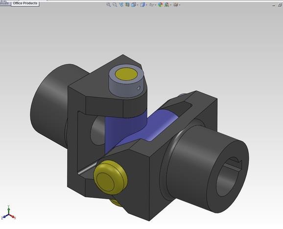
32 Assembled View
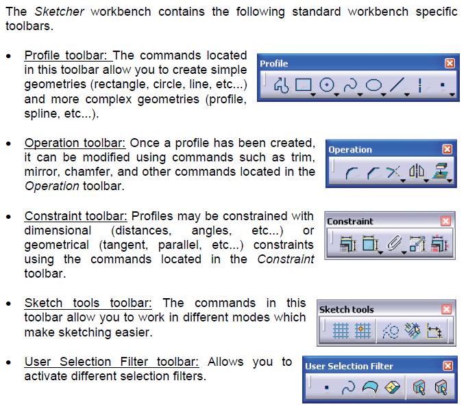
33 SHRI SHIVAJI EDUCATION SOCIETY, AMRAVATI S, COLLEGE OF ENGINEERING & TECHNOLOGY, AKOLA Babhulgaon (JH) N.H.No.6, Akola DEPARTMENT OF MECHANICAL ENGINEERING COMPUTER SOFTWARE APPLICATIONS -I LAB. (5ME10) EXPERIMENT NO: - 5 NAME OF EXPERIMENT: - Creation of 3D detailed part for any sheet metal components is using 3D Product modeling software. Sheet metal modeling in Pro/E consists of a different set of features that help us to create Sheet metal model faster and more accurate. Features like bend, unbend, punch, Sheet metal cut, corner relief, form, extended wall, flat pattern etc are created for Sheet metal part modeling. Most of the Pro/E Sheet metal features are still using the menu manager (pre- Wildfire) interface. For example: none of Sheet metal feature was being modernized in Pro/E Wildfire. Only two features (create flat wall and create flange wall) were modernized in Pro/E Wildfire 4.0 and new interface for first wall and Sheet metal cut is introduced in Pro/E Wildfire 4.0. As what I can say, so far, more than 50% of the Sheet metal feature has not been modernized yet. There are many Wildfire users who are not familiar to the old interface. This tutorial is created base on Pro/ENGINEER Wildfire To create a new Sheet metal part, click new, then select part and Sheet metal in the dialog box.

34 2. A set of Sheet metal icons appear to you. You should notice that almost all the icons are set inactive except the unattached wall. Let us create the first wall of Sheet metal part using unattached flat wall. 3. The unattached flat wall s dialog box and menu manager appears. The system is now waiting for the sketching plane input.


35 4. Pick the plane which you want to start a sketch


36 5. Next, you will need to specify the sketching plane direction. Choose the direction and pick Okay 6. After that specify the view orientation for your sketch. Pick default for default orientation 7. You are now entering the sketch mode. Sketch the desire shape and press the check button


37 8. At the message area, you will need to input the Sheet metal thickness. After that, click the OK button in the dialog box to confirm the feature creation. 10. Sheet metal flat wall is created.
The Department of Construction Management and Civil Engineering Technology CMCE-1110 Construction Drawings 1 Lecture Introduction to AutoCAD What is
 The Department of Construction Management and Civil Engineering Technology CMCE-1110 Construction Drawings 1 Lecture Introduction to AutoCAD What is AutoCAD? The term CAD (Computer Aided Design /Drafting)
Lesson 1 Parametric Modeling Fundamentals
 1-1 Lesson 1 Parametric Modeling Fundamentals Create Simple Parametric Models. Understand the Basic Parametric Modeling Process. Create and Profile Rough Sketches. Understand the "Shape before size" approach.
Curriculum Guide. Creo 4.0
 Curriculum Guide Creo 4.0 Live Classroom Curriculum Guide Update to Creo Parametric 4.0 from Creo Parametric 3.0 Introduction to Creo Parametric 4.0 Advanced Modeling using Creo Parametric 4.0 Advanced
WILDFIRE 4.0. Sheetmetal Assembly of a Bucket. Yves Gagnon, M.A.Sc. SDC
 INTRODUCTION TO PRO/SHEETMETAL WILDFIRE 4.0 Sheetmetal Assembly of a Bucket Yves Gagnon, M.A.Sc. SDC PUBLICATIONS Schroff Development Corporation www.schroff.com www.schroff-europe.com Estimated time:
Live Classroom Curriculum Guide
 Curriculum Guide Live Classroom Curriculum Guide Milling using Pro/ENGINEER Wildfire 4.0 Pro/ENGINEER Mechanica Simulation using Pro/ENGINEER Wildfire 4.0 Introduction to Pro/ENGINEER Wildfire 4.0 Pro/ENGINEER
Technique or Feature Where Introduced
 Part 6: Keypad 4 Mirrored features Patterned features First extrusion Rounded corners In the earpiece part, you defined a radial pattern, one that created new instances of a feature at intervals around
WILDFIRE 3.0. Sheetmetal Assembly of a Bucket. Yves Gagnon, M.A.Sc. SDC
 INTRODUCTION TO PRO/SHEETMETAL WILDFIRE 3.0 Sheetmetal Assembly of a Bucket Yves Gagnon, M.A.Sc. SDC PUBLICATIONS Schroff Development Corporation www.schroff.com www.schroff-europe.com Estimated time:
Autodesk Fusion 360 Training: The Future of Making Things Attendee Guide
 Autodesk Fusion 360 Training: The Future of Making Things Attendee Guide Abstract After completing this workshop, you will have a basic understanding of editing 3D models using Autodesk Fusion 360 TM to
Feature-Based Modeling and Optional Advanced Modeling. ENGR 1182 SolidWorks 05
 Feature-Based Modeling and Optional Advanced Modeling ENGR 1182 SolidWorks 05 Today s Objectives Feature-Based Modeling (comprised of 2 sections as shown below) 1. Breaking it down into features Creating
Tutorial Second Level
 AutoCAD 2018 Tutorial Second Level 3D Modeling Randy H. Shih SDC PUBLICATIONS Better Textbooks. Lower Prices. www.sdcpublications.com Powered by TCPDF (www.tcpdf.org) Visit the following websites to learn
Module 1: Basics of Solids Modeling with SolidWorks
 Module 1: Basics of Solids Modeling with SolidWorks Introduction SolidWorks is the state of the art in computer-aided design (CAD). SolidWorks represents an object in a virtual environment just as it exists
Autodesk Inventor 6 Essentials Instructor Guide Chapter Four: Creating Placed Features Chapter Outline This chapter provides instruction on the follow
 Chapter Four: Creating Placed Features Chapter Outline This chapter provides instruction on the following topics and provides exercises for students to practice their skills. Day Two Topic: How to create
Acknowledgement INTRODUCTION
 Submitted by: 1 Acknowledgement INTRODUCTION Computers are increasingly being used for doing engineering drawings and graphics work because computers allow the graphics designer or the draughtsman to change
Parametric Modeling. With. Autodesk Inventor. Randy H. Shih. Oregon Institute of Technology SDC PUBLICATIONS
 Parametric Modeling With Autodesk Inventor R10 Randy H. Shih Oregon Institute of Technology SDC PUBLICATIONS Schroff Development Corporation www.schroff.com www.schroff-europe.com 2-1 Chapter 2 Parametric
An Introduction to Autodesk Inventor 2010 and AutoCAD Randy H. Shih SDC PUBLICATIONS. Schroff Development Corporation
 An Introduction to Autodesk Inventor 2010 and AutoCAD 2010 Randy H. Shih SDC PUBLICATIONS Schroff Development Corporation www.schroff.com 2-1 Chapter 2 Parametric Modeling Fundamentals Create Simple Extruded
AutoCAD D. Introduction to computer
 AutoCAD 2010 2D Introduction to computer Introduction to AutoCAD Screen Layout. Limits, Units Dsettings (Isoplane, Snap) Line,Circle,Arc, Erase, New, Open, Save, Save as Qnew Open Close Quit Polygon Move
Creo for Analyst. Overview
 Creo for Analyst Overview In this course, you will learn how to utilize the core functionality enhancements in Creo Parametric 2.0. First, you will become familiar with using and customizing the new ribbon
SpaceClaim Professional The Natural 3D Design System. Advanced Technology
 SpaceClaim Professional The Natural 3D Design System SpaceClaim Professional is the 3D productivity tool for engineers who contribute to the design and manufacture of mechanical products across a broad
Course Modules for CATIA V6 2013x Essentials for New Users Training Online:
 Course Modules for CATIA V6 2013x - 100 Essentials for New Users Training Online: 1 Launching CATIA V6 The PLM Story Import IGI Models (Essentials) Launching CATIA V6 Choosing a Security Context 2 V6 Navigation
Equipment Support Structures
 Equipment Support Structures Overview Conventions What's New? Getting Started Setting Up Your Session Creating a Simple Structural Frame Creating Non-uniform Columns Creating Plates with Openings Bracing
Equipment Support Structures
 Page 1 Equipment Support Structures Preface Using This Guide Where to Find More Information Conventions What's New? Getting Started Setting Up Your Session Creating a Simple Structural Frame Creating Non-uniform
Creo 2.0. Curriculum Guide
 Creo 2.0 Curriculum Guide Live Classroom Curriculum Guide Update to Creo Parametric 2.0 from Creo Elements/Pro 5.0 Update to Creo Parametric 2.0 from Pro/ENGINEER Wildfire 4.0 Introduction to Creo Parametric
Live Classroom Curriculum Guide
 Curriculum Guide Live Classroom Curriculum Guide Creo Elements/Pro 5.0 (formerly Pro/ENGINEER Wildfire 5.0) Update from Pro/ENGINEER Wildfire 4.0 Creo Elements/Pro 5.0 (formerly Pro/ENGINEER Wildfire 5.0)
An Introduction to Autodesk Inventor 2013 and AutoCAD
 An Introduction to Autodesk Inventor 2013 and AutoCAD 2013 Randy H. Shih SDC PUBLICATIONS Schroff Development Corporation Better Textbooks. Lower Prices. www.sdcpublications.com Visit the following websites
Exercise Guide. Published: August MecSoft Corpotation
 VisualCAD Exercise Guide Published: August 2018 MecSoft Corpotation Copyright 1998-2018 VisualCAD 2018 Exercise Guide by Mecsoft Corporation User Notes: Contents 2 Table of Contents About this Guide 4
Parametric Modeling with UGS NX 4
 Parametric Modeling with UGS NX 4 Randy H. Shih Oregon Institute of Technology SDC PUBLICATIONS Schroff Development Corporation www.schroff.com www.schroff-europe.com 2-1 Chapter 2 Parametric Modeling
After completing this lesson, you will be able to:
 LEARNING OBJECTIVES After completing this lesson, you will be able to: 1. Create a template. 2. Understand the AutoCAD Window. 3. Understand the use of the function keys. 4. Select commands using the Pull-down
An Introduction to Autodesk Inventor 2012 and AutoCAD Randy H. Shih SDC PUBLICATIONS. Schroff Development Corporation
 An Introduction to Autodesk Inventor 2012 and AutoCAD 2012 Randy H. Shih SDC PUBLICATIONS www.sdcpublications.com Schroff Development Corporation Visit the following websites to learn more about this book:
Structural & Thermal Analysis using the ANSYS Workbench Release 11.0 Environment. Kent L. Lawrence
 ANSYS Workbench Tutorial Structural & Thermal Analysis using the ANSYS Workbench Release 11.0 Environment Kent L. Lawrence Mechanical and Aerospace Engineering University of Texas at Arlington SDC PUBLICATIONS
The Rectangular Problem
 C h a p t e r 2 The Rectangular Problem In this chapter, you will cover the following to World Class standards: The tools for simple 2D Computer Aided Drafting (CAD) The Command Line and the Tray The Line
SolidWorks 2013 and Engineering Graphics
 SolidWorks 2013 and Engineering Graphics An Integrated Approach Randy H. Shih SDC PUBLICATIONS Schroff Development Corporation Better Textbooks. Lower Prices. www.sdcpublications.com Visit the following
An Overview of Pro/ENGINEER
 An Overview of Pro/ENGINEER The Foundation of Pro/ENGINEER What is Pro/ENGINEER? Pro/ENGINEER is a computer graphics system for modeling various mechanical designs and for performing related design and
Chapter 2 Parametric Modeling Fundamentals
 2-1 Chapter 2 Parametric Modeling Fundamentals Create Simple Extruded Solid Models Understand the Basic Parametric Modeling Procedure Create 2-D Sketches Understand the "Shape before Size" Approach Use
Tutorial 3: Constructive Editing (2D-CAD)
") (2D-CAD) The editing done up to now is not much different from the normal drawing board techniques. This section deals with commands to copy items we have already drawn, to move them and to make multiple
(2D-CAD) The editing done up to now is not much different from the normal drawing board techniques. This section deals with commands to copy items we have already drawn, to move them and to make multiple
After completing this lesson, you will be able to:
 LEARNING OBJECTIVES After completing this lesson, you will be able to: 1. Create a template. 2. Understand the AutoCAD Window. 3. Understand the use of the function keys. 4. Select commands using the Pull-down
Parametric Modeling with. Autodesk Fusion 360. First Edition. Randy H. Shih SDC. Better Textbooks. Lower Prices.
 Parametric Modeling with Autodesk Fusion 360 First Edition Randy H. Shih SDC PUBLICATIONS Better Textbooks. Lower Prices. www.sdcpublications.com Powered by TCPDF (www.tcpdf.org) Visit the following websites
Structural & Thermal Analysis Using the ANSYS Workbench Release 12.1 Environment
 ANSYS Workbench Tutorial Structural & Thermal Analysis Using the ANSYS Workbench Release 12.1 Environment Kent L. Lawrence Mechanical and Aerospace Engineering University of Texas at Arlington SDC PUBLICATIONS
SolidWorks Implementation Guides. User Interface
 SolidWorks Implementation Guides User Interface Since most 2D CAD and SolidWorks are applications in the Microsoft Windows environment, tool buttons, toolbars, and the general appearance of the windows
Pro/ENGINEER Wildfire 3.0 Curriculum Guide
 Pro/ENGINEER Wildfire 3.0 Curriculum Guide NOTE: For a graphical depiction of the curriculum based on job role, please visit this page: http://www.ptc.com/services/edserv/learning/paths/ptc/proe_wf3.htm
Parametric Modeling. with. Autodesk Inventor Randy H. Shih. Oregon Institute of Technology SDC
 Parametric Modeling with Autodesk Inventor 2009 Randy H. Shih Oregon Institute of Technology SDC PUBLICATIONS Schroff Development Corporation www.schroff.com Better Textbooks. Lower Prices. 2-1 Chapter
Creo 3.0. Curriculum Guide
 Creo 3.0 Curriculum Guide Live Classroom Curriculum Guide Update to Creo Parametric 3.0 from Creo Parametric 2.0 Introduction to Creo Parametric 3.0 Advanced Modeling using Creo Parametric 3.0 Advanced
Education Curriculum Surface Design Specialist
 Education Curriculum Surface Design Specialist Invest your time in imagining next generation designs. Here s what we will teach you to give shape to your imagination. CATIA Surface Design Specialist CATIA
3D Modeling and Design Glossary - Beginner
 3D Modeling and Design Glossary - Beginner Align: to place or arrange (things) in a straight line. To use the Align tool, select at least two objects by Shift left-clicking on them or by dragging a box
Pro/ENGINEER Wildfire 2.0 Curriculum
 Pro/ENGINEER Wildfire 2.0 Curriculum Live Classroom Virtual Class Web Based NOTE: For a graphical depiction of the curriculum based on job role, please visit this page: http://www.ptc.com/services/edserv/learning/paths/ptc/proe_wf2.htm
SOLIDWORKS 2016 and Engineering Graphics
 SOLIDWORKS 2016 and Engineering Graphics An Integrated Approach Randy H. Shih SDC PUBLICATIONS Better Textbooks. Lower Prices. www.sdcpublications.com Powered by TCPDF (www.tcpdf.org) Visit the following
Lesson 14 Blends. For Resources go to > click on the Creo Parametric 2.0 Book cover
 Lesson 14 Blends Figure 14.1 Cap OBJECTIVES Create a Parallel Blend feature Use the Shell Tool Create a Hole Pattern REFERENCES AND RESOURCES For Resources go to www.cad-resources.com > click on the Creo
CATIA V5-6R2015 Product Enhancement Overview
 Click to edit Master title style CATIA V5-6R2015 Product Enhancement Overview John Montoya, PLM Technical Support March 2015 1 2010 Inceptra LLC. All rights reserved. Overview of Enhanced Products Overview
Pro/ENGINEER Concepts
 1 Pro/ENGINEER Concepts Becoming a Pro/ENGINEER user means learning to think in terms of how the components of a design interact, and to think ahead to how those interactions may change. At the simplest
TRAINING SESSION Q3 2016
 There are 6 main topics in this training session which is focusing on 3D Import and 2D Drawing Tips and Tricks in IRONCAD. Content 3D modeling kernels... 2 3D Import... 3 Direct Face Modeling... 5 Unfold
Solidworks 2006 Surface-modeling
 Solidworks 2006 Surface-modeling (Tutorial 2-Mouse) Surface-modeling Solid-modeling A- 1 Assembly Design Design with a Master Model Surface-modeling Tutorial 2A Import 2D outline drawing into Solidworks2006
6. CAD SOFTWARE. CAD is a really useful tool for every engineer, and especially for all the designers.
 6. CAD SOFTWARE CAD is a really useful tool for every engineer, and especially for all the designers. Not only because it makes drawing easier, but because it presents the advantage that if any detail
Solid Modeling: Part 1
 Solid Modeling: Part 1 Basics of Revolving, Extruding, and Boolean Operations Revolving Exercise: Stepped Shaft Start AutoCAD and use the solid.dwt template file to create a new drawing. Create the top
SheetMetal Design Version 5 Release 13. SheetMetal Design
 SheetMetal Design Page 1 Overview Conventions What's New? Getting Started Entering the Workbench Defining the Parameters Creating the First Wall Creating the Side Walls Creating a Cutout Creating Automatic
Autodesk Inventor 2018
 Learning Autodesk Inventor 2018 Modeling, Assembly and Analysis Randy H. Shih SDC PUBLICATIONS Better Textbooks. Lower Prices. www.sdcpublications.com Powered by TCPDF (www.tcpdf.org) Visit the following
2D CAD. Courseware Issued: DURATION: 64 hrs
 2D CAD Introduction File management Orthographic drawings View management Display management Layer management Selection methods Parametric drawings Symbol creation using block BOM / Joinery details creation
Tools for Design. with VEX Robot Kit: Randy H. Shih Oregon Institute of Technology SDC PUBLICATIONS
 Tools for Design with VEX Robot Kit: AutoCAD 2011 and Autodesk Inventor 2011 2D Drawing 3D Modeling Hand Sketching Randy H. Shih Oregon Institute of Technology INSIDE: SUPPLEMENTAL FILES ON CD SDC PUBLICATIONS
Autodesk Fusion 360: Model. Overview. Modeling techniques in Fusion 360
 Overview Modeling techniques in Fusion 360 Modeling in Fusion 360 is quite a different experience from how you would model in conventional history-based CAD software. Some users have expressed that it
Introduction To Finite Element Analysis
 Creating a Part In this part of the tutorial we will introduce you to some basic modelling concepts. If you are already familiar with modelling in Pro Engineer you will find this section very easy. Before
Lesson 14 Blends. For Resources go to > click on the Creo Parametric Book cover
 Lesson 14 Blends Figure 14.1 Cap OBJECTIVES Create a Parallel Blend feature Use the Shell Tool Create a Swept Blend REFERENCES AND RESOURCES For Resources go to www.cad-resources.com > click on the Creo
Generative Shape Design
 Generative Shape Design Copyright DASSAULT SYSTEMES 2002 1 Exercise 60 min. The Knob In this exercise you will have the opportunity to model an appliance Knob starting from an empty model. You will create
Randy H. Shih. Jack Zecher PUBLICATIONS
 Randy H. Shih Jack Zecher PUBLICATIONS WWW.SDCACAD.COM AutoCAD LT 2000 MultiMedia Tutorial 1-1 Lesson 1 Geometric Construction Basics! " # 1-2 AutoCAD LT 2000 MultiMedia Tutorial Introduction Learning
Autodesk Inventor 2016 Learn by doing. Tutorial Books
 Autodesk Inventor 2016 Learn by doing Tutorial Books Copyright 2015 Kishore This book may not be duplicated in any way without the express written consent of the publisher, except in the form of brief
PTC Technical Specialists E-Newsletter Date: December 1, 2006
 PTC Technical Specialists E-Newsletter Date: December 1, 2006 PTC Product Focus: A) What s New in Sheetmetal Design for Wildfire 3.0 B) Windchill 3 rd Party Workgroup Managers Tips of the Month: A) Creating
Solid Edge ST3. for Engineers and Designers. CADCIM Technologies 525 St. Andrews Drive Schererville, IN 46375, USA (
 Solid Edge ST3 for Engineers and Designers CADCIM Technologies 525 St. Andrews Drive Schererville, IN 46375, USA (www.cadcim.com) Contributing Author Sham Tickoo Professor Department of Mechanical Engineering
SolidWorks Intro Part 1b
 SolidWorks Intro Part 1b Dave Touretzky and Susan Finger 1. Create a new part We ll create a CAD model of the 2 ½ D key fob below to make on the laser cutter. Select File New Templates IPSpart If the SolidWorks
SolidWorks 2015 User Interface
 SolidWorks 2015 User Interface SolidWorks a Dassault Systèmes Product Starting SolidWorks 1) On the desktop, double-click or from the start menu select: All Programs SOLIDWORKS 2015 SOLIDWORKS 2015. 2)
Dave s Phenomenal Maya Cheat Sheet Polygon Modeling Menu Set By David Schneider
 Dave s Phenomenal Maya Cheat Sheet Polygon Modeling Menu Set By David Schneider POLYGONS NURBS to Polygons This allows the user to change the objects created with NURBS into polygons so that polygon tools
Inventor 201. Work Planes, Features & Constraints: Advanced part features and constraints
 Work Planes, Features & Constraints: 1. Select the Work Plane feature tool, move the cursor to the rim of the base so that inside and outside edges are highlighted and click once on the bottom rim of the
Sheet Metal Overview. Chapter. Chapter Objectives
 Chapter 1 Sheet Metal Overview This chapter describes the terminology, design methods, and fundamental tools used in the design of sheet metal parts. Building upon these foundational elements of design,
Chapter 2 Parametric Modeling Fundamentals
 2-1 Chapter 2 Parametric Modeling Fundamentals Create Simple Extruded Solid Models Understand the Basic Parametric Modeling Procedure Create 2-D Sketches Understand the Shape before Size Approach Use the
A Comprehensive Introduction to SolidWorks 2011
 A Comprehensive Introduction to SolidWorks 2011 Godfrey Onwubolu, Ph.D. SDC PUBLICATIONS www.sdcpublications.com Schroff Development Corporation Chapter 2 Geometric Construction Tools Objectives: When
SolidWorks 2½D Parts
 SolidWorks 2½D Parts IDeATe Laser Micro Part 1b Dave Touretzky and Susan Finger 1. Create a new part In this lab, you ll create a CAD model of the 2 ½ D key fob below to make on the laser cutter. Select
Learning Autodesk Inventor 2014
 Learning Autodesk Inventor 2014 Modeling, Assembly and Analysis Randy H. Shih SDC P U B L I C AT I O N S Better Textbooks. Lower Prices. www.sdcpublications.com Visit the following websites to learn more
ARCHITECTURE & GAMES. A is for Architect Simple Mass Modeling FORM & SPACE. Industry Careers Framework. Applied. Getting Started.
 A is for Architect Simple Mass Modeling One of the first introductions to form and space usually comes at a very early age. As an infant, you might have played with building blocks to help hone your motor
Update to Creo Parametric 4.0 from Creo Parametric 2.0
 Update to Creo from Creo Parametric 2.0 Overview Course Code Course Length TRN-5125-T 16 Hours In this course, you will learn how to utilize the variety of functionality enhancements in Creo. You will
Tools for Design. A practical guide to 2D Drawing, Sketching, 3D Parametric Modeling and Finite Element Analysis
 Tools for Design Using AutoCAD 2011, Autodesk Inventor 2011, and LEGO MINDSTORMS NXT & TETRIX A practical guide to 2D Drawing, Sketching, 3D Parametric Modeling and Finite Element Analysis INSIDE: SUPPLEMENTAL
Parametric Modeling with NX 12
 Parametric Modeling with NX 12 NEW Contains a new chapter on 3D printing Randy H. Shih SDC PUBLICATIONS Better Textbooks. Lower Prices. www.sdcpublications.com Powered by TCPDF (www.tcpdf.org) Visit the
Additional Exercises. You will perform the following exercises to practice the concepts learnt in this course:
 Additional Exercises You will perform the following exercises to practice the concepts learnt in this course: Master Exercise : Mobile Phone Plastic Bottle Exercise 1 Master Exercise : Mobile Phone In
Modeling a Gear Standard Tools, Surface Tools Solid Tool View, Trackball, Show-Hide Snaps Window 1-1
 Modeling a Gear This tutorial describes how to create a toothed gear. It combines using wireframe, solid, and surface modeling together to create a part. The model was created in standard units. To begin,
SOLIDWORKS Parametric Modeling with SDC. Covers material found on the CSWA exam. Randy H. Shih Paul J. Schilling
 Parametric Modeling with SOLIDWORKS 2015 Covers material found on the CSWA exam Randy H. Shih Paul J. Schilling SDC PUBLICATIONS Better Textbooks. Lower Prices. www.sdcpublications.com Powered by TCPDF
FreeStyle Shaper & Optimizer
 FreeStyle Shaper & Optimizer Preface What's New Getting Started Basic Tasks Advanced Tasks Workbench Description Customizing Glossary Index Dassault Systèmes 1994-99. All rights reserved. Preface CATIA
Input CAD Solid Model Assemblies - Split into separate Part Files. DXF, IGES WMF, EMF STL, VDA, Rhino Parasolid, ACIS
 General NC File Output List NC Code Post Processor Selection Printer/Plotter Output Insert Existing Drawing File Input NC Code as Geometry or Tool Paths Input Raster Image Files Report Creator and Designer
Lesson 5 Solid Modeling - Constructive Solid Geometry
 AutoCAD 2000i Tutorial 5-1 Lesson 5 Solid Modeling - Constructive Solid Geometry Understand the Constructive Solid Geometry Concept. Create a Binary Tree. Understand the basic Boolean Operations. Create
Advance Design. Tutorial
 TUTORIAL 2018 Advance Design Tutorial Table of Contents About this tutorial... 1 How to use this guide... 3 Lesson 1: Preparing and organizing your model... 4 Step 1: Start Advance Design... 5 Step 2:
Appendix B: Creating and Analyzing a Simple Model in Abaqus/CAE
 Getting Started with Abaqus: Interactive Edition Appendix B: Creating and Analyzing a Simple Model in Abaqus/CAE The following section is a basic tutorial for the experienced Abaqus user. It leads you
Structure Preliminary Layout
 Page 1 Structure Preliminary Layout Preface Using This Guide Where to Find More Information What's New? Getting Started Setting Up Your Session Defining the Hull Form Setting Up Your Grid Creating Molded
7/21/2009. Chapters Learning Objectives. Fillet Tool
 Chapters 12-13 JULY 21, 2009 Learning Objectives Chapter 12 Chapter 13 Use the FILLET tool to draw fillets, rounds, and other rounded corners. Place chamfers and angled corners with the CHAMFER tool. Separate
3 AXIS STANDARD CAD. BobCAD-CAM Version 28 Training Workbook 3 Axis Standard CAD
 3 AXIS STANDARD CAD This tutorial explains how to create the CAD model for the Mill 3 Axis Standard demonstration file. The design process includes using the Shape Library and other wireframe functions
Photocopiable/digital resources may only be copied by the purchasing institution on a single site and for their own use ZigZag Education, 2013
 SketchUp Level of Difficulty Time Approximately 15 20 minutes Photocopiable/digital resources may only be copied by the purchasing institution on a single site and for their own use ZigZag Education, 2013
Chapter 20 Assembly Model with VEX Robot Kit - Autodesk Inventor
 Tools for Design Using AutoCAD and Autodesk Inventor 20-1 Chapter 20 Assembly Model with VEX Robot Kit - Autodesk Inventor Creating an Assembly Using Parts from the VEX Robot Kit Understand and Perform
Finite Element Analysis Using Pro/Engineer
 Appendix A Finite Element Analysis Using Pro/Engineer A.1 INTRODUCTION Pro/ENGINEER is a three-dimensional product design tool that promotes practices in design while ensuring compliance with industry
Tools for Design. Using AutoCAD 2015 and Autodesk Inventor 2015 SDC. Hand Sketching, 2D Drawing and 3D Modeling. Randy H. Shih
 Tools for Design Using AutoCAD 2015 and Autodesk Inventor 2015 Hand Sketching, 2D Drawing and 3D Modeling Randy H. Shih SDC PUBLICATIONS Better Textbooks. Lower Prices. www.sdcpublications.com Powered
Parametric Modeling with SolidWorks
 Parametric Modeling with SolidWorks 2012 LEGO MINDSTORMS NXT Assembly Project Included Randy H. Shih Paul J. Schilling SDC PUBLICATIONS Schroff Development Corporation Better Textbooks. Lower Prices. www.sdcpublications.com
Module 5: Creating Sheet Metal Transition Piece Between a Square Tube and a Rectangular Tube with Triangulation
 1 Module 5: Creating Sheet Metal Transition Piece Between a Square Tube and a Rectangular Tube with Triangulation In Module 5, we will learn how to create a 3D folded model of a sheet metal transition
Introduction to Solid Modeling Parametric Modeling. Mechanical Engineering Dept.
 Introduction to Solid Modeling Parametric Modeling 1 Why draw 3D Models? 3D models are easier to interpret. Simulation under real-life conditions. Less expensive than building a physical model. 3D models
Parametric Modeling with SOLIDWORKS 2017
 Parametric Modeling with SOLIDWORKS 2017 NEW Contains a new chapter on 3D printing Covers material found on the CSWA exam Randy H. Shih Paul J. Schilling SDC PUBLICATIONS Better Textbooks. Lower Prices.
Autodesk Fusion 360: Introduction. Overview
 Overview Fusion 360 is a cloud-based CAD/CAM tool for collaborative product development. The tools in Fusion enable exploration and iteration on product ideas and collaboration within a product development
Module 4A: Creating the 3D Model of Right and Oblique Pyramids
 Inventor (5) Module 4A: 4A- 1 Module 4A: Creating the 3D Model of Right and Oblique Pyramids In Module 4A, we will learn how to create 3D solid models of right-axis and oblique-axis pyramid (regular or
Geometric Modeling. Introduction
 Geometric Modeling Introduction Geometric modeling is as important to CAD as governing equilibrium equations to classical engineering fields as mechanics and thermal fluids. intelligent decision on the
Glider. Wing. Top face click Sketch. on the Standard Views. (S) on the Sketch toolbar.
 on the Sketch toolbar.") Chapter 5 Glider Wing 4 Panel Tip A. Open and Save As "WING 4 PANEL". Step 1. Open your WING BLANK file. Step 2. Click File Menu > Save As. Step 3. Key-in WING 4 PANEL for the filename and press ENTER.
Chapter 5 Glider Wing 4 Panel Tip A. Open and Save As "WING 4 PANEL". Step 1. Open your WING BLANK file. Step 2. Click File Menu > Save As. Step 3. Key-in WING 4 PANEL for the filename and press ENTER.