Structure Preliminary Layout
|
|
|
- Elvin Byrd
- 5 years ago
- Views:
Transcription
1 Page 1 Structure Preliminary Layout Preface Using This Guide Where to Find More Information What's New? Getting Started Setting Up Your Session Defining the Hull Form Setting Up Your Grid Creating Molded Forms Creating a Compartment Creating Boundaries Saving Documents User Tasks Browsing Project Data Wrapping Surfaces About Wrapping Surfaces Preparing Imported Surfaces Creating Hull Forms Creating Deckhouses Creating Complex Hull Forms Modifying Wrapping Surfaces Replacing Wrapping Surfaces Calculating General Hull Characteristics and Form Coefficients Molded Forms About Molded Forms Creating Simple Molded Forms Creating Multiple Molded Forms Creating External Molded Forms Modifying Molded Forms Compartments About Compartments Creating Compartments Modifying Compartments Modifying Compartment User Type Creating Complex Compartments Boundaries Creating Boundaries Modifying Boundary User Type Openings
2 Page 2 Creating Openings Deleting Openings Exporting Data in IDF Format Generating Offset Data Creating Reports Producing Lines Drawings Creating Plane Systems Managing Your Project Working with a Cache System Managing Ship Project Data Understanding Project Resource Management About the Feature Dictionary About Object Naming Rules Structure Preliminary Layout Package in Knowledge Expert Interoperability Working with ENOVIA LCA: Optimal CATIA PLM Usability Taking Advantage of ENOVIA LCA Capabilities Working with SmarTeam Workbench Description Structure Preliminary Layout Toolbar Structure Grid Set Toolbar Specification Tree Customizing Structure Preliminary Layout Design Drafting Offset Data Glossary Index

3 Page 3 Preface Version 5 Structure Preliminary Layout allows you to model the early definition of hull forms, major ship zones and main structures. It offers an easy-to-use and easy-to-learn graphic interface. The overall ship design project goes through a number of different phases from conceptual design through functional and detail design to extraction of deliverables. This product addresses initial design requirements for the shipbuilding industry. It focuses on internal arrangement and definition, including major bulkheads and decks, on subdivision into compartments of simple and complex shapes, and lets you compute data used in hydrostatic analyses. Other outputs include lines drawings, project data in IDF format and offset data in XML format. This early definition of the ship will then be further refined during the functional and detail design phases. As a scalable product, Structure Preliminary Layout can be used with other Version 5 products such as Generative Drafting 2 (GRD) and Generative Shape Design 2 (GSD).
4 Page 4 Using This Guide Where to Find More Information
5 Page 5 Using This Guide This book is intended to help you become quickly familiar with Structure Preliminary Layout. You should already be accustomed with basic Version 5 concepts such as document windows, standard and view toolbars. This guide is organized as follows: Getting Started: steps you through a scenario to get you acquainted with the product. Basic Tasks: provides a step-by-step guide for using Structure Preliminary Layout. Useful tips are given for getting the most out of the product. Advanced Tasks: provides information on the feature dictionary and useful tools. Workbench Description: describes the Structure Preliminary Layout dedicated workbench toolbar. Customizing: contains information allowing you to customize your personal environment. Glossary: defines terms that are specific to Structure Preliminary Layout.
6 Page 6 Where to Find More Information Prior to reading this book, we recommend that you read the Version 5 Infrastructure User's Guide. The Generative Drafting and Generative Shape Design User's Guides may also prove useful.
7 Page 7 What's New? New Functionality Working with SmarTeam You can manage Structure Preliminary Layout documents in SmarTeam Enhanced Functionality Working with ENOVIA LCA: Optimal CATIA PLM Usability All data created in Structure Preliminary Layout can be correctly saved in ENOVIA LCA Creating Compartments A single compartment object is now managed. Two commands are available depending on whether you want to create compartments of simple geometry (old Bounded Zone command) or complex geometry (old Composite Volume command) Replacing wrapping surfaces Manages hull form replacement within Structure Preliminary Layout Recommendations on how to save documents have been included.
8 Page 8 Getting Started This tutorial will guide you step-by-step through your first Structure Preliminary Layout session, allowing you to get acquainted with the product. You will need a Version 5 session and should be familiar with basic concepts such as document windows, standard and view toolbars. You should be able to complete this tutorial in about 30 minutes. Setting Up Your Session Defining the Hull Form Setting Up Your Grid Creating Molded Forms Creating a Compartment Creating Boundaries Saving Documents
9 Page 9 Setting Up Your Session This task shows you how to enter the Structure Preliminary Layout workbench. 1.Select Equipment & Systems -> Structure Preliminary Layout from the Start menu. The Structure Preliminary Layout workbench is loaded and an empty CATProduct document is opened.

10 Page 10 2.To ensure associativity between items you create and the entities selected to create them, set the following option: Select Tools -> Options from the menu bar Select Infrastructure -> Part Infrastructure in the left-hand box of the Options dialog box Click the General tab Select Keep link with selected objects. 3.To define default colors for molded forms, compartments and boundaries: Select the Equipment & Systems category Select Structure Preliminary Layout, then select the Design tab Set molded form color to purple. Set bounded zone color to yellow. Set boundary color to red. 4.Click OK in the Options dialog box when done.
11 Defining the Hull Form Page 11 This task shows you how to define the hull form. Defining the hull form is done in several different steps: Add a wrapping surface feature Import the surface into Structure Preliminary Layout Edit the wrapping surface feature to associate the imported surface to the feature and orient the surface properly. 1. Click the Wrapping Surface icon. The Wrapping Surface Class Definition dialog box appears. You will keep the default object class. 2. Click OK in the Wrapping Surface Class Definition dialog box to define the wrapping surface feature. The feature is added to the specification tree. You are ready to import the hull form surface. 3. Open the HullForm.CATPart containing the surface to be used for the hull form. The sample CATPart is located in the samples folder. It is opened in a separate document. 4. Tile both windows horizontally. 5. Copy the surface (last feature defining the surface). 6. Paste it in the Ship Project document at reference part level using the Paste Special... command, As Result option.


12 Page 12 The copied surface is pasted under Wrapping Surface Geometry. 7. If necessary, update your document. You will now associate the imported surface to the wrapping surface feature. 8. Right-click the wrapping surface feature and select Edit wrapping surface from the contextual menu:
13 Page 13 The Wrapping Surface dialog box appears. 9. Select the surface just pasted. The wrapping surface is identified in the dialog box. Note: Set as default is set to Yes. This means that the wrapping surface is a default surface and will be automatically proposed when performing other operations, such as creating molded forms. 10. Click Switch orientation name to obtain the correct wrapping surface orientation. 11. Click OK when done. The hull form has been defined and published.

14 Page 14 Setting Up Your Grid This task shows you how to create the cross and deck plane systems you need to define ship bulkheads and decks. Note: It is recommended that one CATPart contain the set of reference planes in one ship direction only. 1. Activate the project and select the Plane System command. A new part is added to the specification tree and the Plane System dialog box appears. 2. Create the cross plane system: Click the yz plane of the new part just added to define the direction. The center of the plane is automatically taken as its origin. Enter a spacing of mm to define the distance between planes Enter 4 in the Number of planes after origin field to create four planes before and four planes after the origin Click OK to create the cross plane system. 3. Repeat to create a deck plane system comprising four planes 5500 mm apart, two on either side of the origin (XY plane).
15 Page 15

16 Creating Molded Forms Page 16 This task shows you how to create bulkhead and deck molded forms. 1. Click the Molded Form icon. The Molded Form Definition dialog box appears. You will keep the default object class. 2. Define the reference element: select the YZ reference plane. The reference element gives the basic shape to your molded form. You will now select the limiting elements to which the molded form will be trimmed. 3. Select the wrapping surface as the first limit: The Basic Wrapping Surface Selection dialog box appears listing all wrapping surfaces with those set as default surfaces in the right-hand column. In our case, there is only one. Click OK. Watch your molded form being trimmed to the limit you selected.


17 Page 17 The preview shows that the bulkhead will be created inside the ship. This is what we want. 4. Select the topmost deck plane to trim the bulkhead to this plane. 5. Click Other side to re-position the bulkhead correctly. 6. Check Molded form orientation in the dialog box: The Molded Form Definition dialog box expands and the orientation is visualized in the geometry area. Orientation is correct.


18 Page Click OK when done. Your transverse bulkhead has been created and published. You will now define a set of bulkheads based on the one you have just created. 8. Click the Multiple Molded Form icon. The Multiple Molded Form Definition dialog box appears. 9. Select the bulkhead you have just created as the reference molded form. 10. Drag (using the left mouse button) to select parallel cross planes in the geometry area using a bounding outline. Selected planes are identified in the dialog box. 11. Click OK and watch other bulkheads being created with the same specifications as the first bulkhead you created. You will now create two decks. 12. Click the Molded Form icon. The Molded Form Definition dialog box displays.


19 Page Select the reference plane for the deck. 14. Select the wrapping surface as limit. 15. Click OK when done. Your first deck is created and published. 16. Repeat to create another deck.
20 Page 20 Creating a Compartment This task shows you how to create a compartment for the engine room. 1. Click the Compartment icon. The Compartment Definition dialog box appears. Note: Limits listed in the dialog box are the naming conventions specified in the ship project. If you remember, you kept the default naming conventions. 2. Click Change... opposite Object class to change the class. The Class Browser opens and accesses the feature dictionary defining object classes.
21 Page Click the Expand tree icon in the Class Browser to view available classes.
22 Page Select Engine Room then click OK. The selected class is identified in the Compartment Definition dialog box. You are now ready to define your compartment. Select the molded forms and wrapping surface corresponding to your compartment limits in the order shown in the dialog box. As you select surfaces, they are identified in the dialog box and the system moves on to the next limit waiting for you to choose it. 4. Select the fore bulkhead. You may like to display the geometry in wireframe mode to make selections easier. A vector appears showing the orientation of the surface. The molded form and orientation are given in the dialog box. 5. If necessary, click the orientation vector to correct the orientation. 6. Select the hullform for the portside limit. 7. Select the aft bulkhead.

23 Page Select the hullform again for the starboard limit. The system realizes that the starboard and portside limits correspond to the same surface and indicates this in the Merge columns opposite these limits. 9. Select the top deck. 10. Select the bottom deck. 11. Click Preview to preview the compartment. 12. Click OK when done. Your compartment has been created.
24 Page 24 Creating Boundaries This task shows you how to automatically create the boundaries of the compartment just defined. 1. Edit the compartment you just created: right-click the compartment feature in the specification tree and select Edit Compartment from the contextual menu. The Compartment Definition dialog box appears. 2. Click Extract Boundaries to automatically create boundaries. 3. Expand the compartment item in the specification tree to view created boundaries.
25 Page Click OK when done.
26 Page 26 Saving Documents This task contains recommendations on saving your documents. Ways in which documents are saved are explained in the Infrastructure User's Guide - Creating, Opening and Saving Documents. You must read that documentation because the various methods are not explained here. This task simply suggests the methodology you should follow in specific circumstances. 1. If you are saving a document to a local machine or network drive it is recommended that you use the "Save Management" command initially. The Propagate Directory command (which is in the Save Management dialog box) should not be used routinely. It is meant to be used in specific circumstances, such as when you want to place all the contents of a document in one directory before sending it to another location. 2. If you are saving a document to another site or network you should use the "Send To" command. In this case, you should be careful about the links for documents such as resolved parts folder or line ID. These links could change to reflect the local network drive to which the documents have been sent. You should make sure they point to the original location - using the Reset button in the Save Management dialog box is one way of doing this. 3. You should check the active document before you execute the Save command. The root product must be the active document if you want to save everything under it.
27 Page 27 User Tasks The tasks you will perform in the Structure Preliminary Layout workbench are related to the general definition of the ship, including hull shape, main decks and bulkheads as well as general layout. Resources & Default Settings Don't forget to set your options correctly before starting to work (Tools -> Options..., Equipment & Systems, Structure Preliminary Layout). Associativity To ensure associativity between the items you create and entities selected to create them, you must check the Keep link with selected object option. This option is set in the Options dialog box (Tools -> Options..., Infrastructure -> Part Infrastructure -> General). Browsing Project Data Wrapping Surfaces Molded Forms Compartments Boundaries Openings Exporting Data in IDF Format Generating Offset Data Creating Reports Producing Lines Drawings Creating Plane Systems Managing Your Project Structure Preliminary Layout Package in Knowledge Expert


28 Browsing Project Data Page 28 Defining the project is an administrator's task and is managed as a project resource. Doing so: Gives the project a name Specifies conventions for main ship directions Specifies conventions for hull form orientations Specifies the overall dimensions of your project. You can browse project data using the Edit Project command. This task shows you how to browse project data. 1. Click the Edit Project icon. The Project Edition dialog box appears. The Project Id field specifies the name given to the project. 2. Click Naming Conventions... to access other project data. The dialog box expands showing adopted conventions for main ship directions (Coordinate System tab) and hull form orientations (Hull Form tab). Ship directions are defined with respect to the coordinate system of the document. 3. Click the Hull Form tab.


29 Page Click the Bounding Box tab. Bounding Box The bounding box specifies the overall project dimensions as defined by the administrator. A set of default dimensions are supplied with the product. The center of the box is positioned at the center of the document. You may need to click the Fit All In bounding box. command to visualize the When you create the wrapping surface, the bounding box is automatically re-dimensioned to include the hull form. If features are created outside the bounding box, consult to the administrator. 5. Click OK when done.
30 Page 30 Wrapping Surfaces About wrapping surfaces Prepare imported surfaces: open the surface, then use Generative Shape Design to orient, analyze and perform necessary operations Create hull forms: add the wrapping surface feature, import the surface and associate the surface to the feature Create deckhouses: create the deckhouse from scratch using Generative Shape Design, then associate it to the wrapping surface feature Use basic wrapping surfaces for complex hull forms: split the imported surface using Generative Shape Design then associate split surfaces to the wrapping surface feature Modify wrapping surfaces: edit the wrapping surface feature and change specifications in the dialog box that appears. Replace wrapping surfaces: import the replacement surface, switch to Generative Shape Design and use the Replace contextual menu command. Calculate general hull characteristics and form coefficients: edit the wrapping surface feature, select the Form Coefficients tab, specify the draft location and click Calculations.


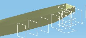
31 Page 31 About Wrapping Surfaces Wrapping surfaces are used to define the hull forms (internal and external) and deckhouse. In the case of hull forms, surfaces are usually imported, whereas for deckhouses they are created from scratch. The wrapping surface can be a single surface or can be made of several surfaces to take into account special cases such as illustrated below. The wrapping surface is an object class managed in the feature dictionary. Note: Shell expansion tools in Structure Functional Design work on hull form halves (portside and starboard wrapping surfaces) or a section of the hull form and not the complete hull form. The transom must be considered a bulkhead and not an integral part of the hull. Managing Wrapping Surface Type You can manage wrapping surface type via the feature dictionary or directly in the Structure Preliminary Layout workbench via the Type attribute. To do so via the Type attribute: Right-click the wrapping surface feature in the specification tree and select the Properties command. The Properties dialog box appears. Click the Conceptual Structure tab. Enter the type, deckhouse for example. Click OK in the Properties dialog box. Object naming rules based on type can also be defined to identify objects in your document. Bounding Box When you create the wrapping surface, the bounding box defining overall project dimensions is automatically redimensioned to include the hull form and deckhouse. The bounding box is managed by the administrator as a project resource. To visualize the bounding box, browse the project data using the Edit Project command.
32 Page 32 Publishing Wrapping surfaces you define are automatically published. This is identified by a Publication entry in the specification tree with one publication feature for each wrapping surface published. If several basic wrapping surfaces are defined, the complete wrapping surface is the result of merging all constituent wrapping surfaces. Molded forms and compartments you create will reference the published surfaces (identified by their publication name) and not the underlying surfaces. This lets you replace the hull form or deckhouse at any time without affecting any downstream work. Do not change publication names of surfaces referenced by molded forms and compartments: links between the two will be lost.

33 Page 33 Preparing Imported Surfaces Imported surfaces are generally used to define wrapping surfaces for the hull (internal and external forms). Before doing so, these surfaces have to be properly positioned in the coordinate system of the document and optimized to obtain a coherent surface. You can import IGES files, idf type and CATPart documents. This task shows you how to open, then position and optimize surfaces. Opening Existing Surfaces 1. Click the Open icon or select the File->Open... command. The File Selection dialog box appears. 2. In the File Selection box, select the file location. 3. In the Files of type drop-down list, select the document type you want to open: CATPart idf igs (IGES file) 4. Click Open. You are now ready to position and optimize your surface. This is done in the Generative Shape Design workbench. Positioning & Optimizing Surfaces 5. Change to the Generative Shape Design workbench (Start -> Shape -> Generative Shape Design). You will begin by positioning the surface in the coordinate system of the document. Doing so defines the main ship directions. When you copy your surface into the ship project, it will be positioned in the same way. 6. Click the Create Datum icon (Tools toolbar) to deactivate the history mode: When you create elements, there are no links to the entities used to create them. 7. Orient the surface using Translate, Rotate, Symmetry and Scaling commands (Insert -> Operations). You can now analyze your surface and perform necessary operations to obtain a coherent surface.
, joining to join surfaces (Join command).")
34 Page Analyze your surface using Analysis commands (Insert -> Analysis) to determine whether healing, joining, etc. is necessary. 9. Perform necessary operations, for example, healing to fill gaps between surfaces (Heal command), joining to join surfaces (Join command). These commands are found in the Insert menu (Insert -> Operations) or in the Operations toolbar. For more information on these tasks, see the appropriate sections in the Generative Shape Design User's Guide. You are now ready to import your surface into Structure Preliminary Layout to create a wrapping surface.
35 Page 35 Creating Hull Forms This task shows you how to create a single wrapping surface for the hull form from an imported surface. In this task, you will: add the wrapping surface feature import the surface into the Structure Preliminary Layout workbench edit the wrapping surface feature to associate the imported surface to the wrapping surface feature and orient the surface properly. Deckhouses are generally not imported surfaces, but are created from scratch. Adding the Wrapping Surface Feature 1. Click the Wrapping Surface icon. The Wrapping Surface Class Definition dialog box appears. The wrapping surface is created under the active product or assembly. 2. Click Change... opposite Object class to change the wrapping surface class. The Class Browser opens and accesses the feature dictionary defining object classes. A sample dictionary is supplied with the product.
36 Page Click the Expand tree icon in the Class Browser to view available classes. 4. Select the class, then click OK. The selected class is identified in the Wrapping Surface Class Definition dialog box.
37 Page Click OK in the Wrapping Surface Class Definition dialog box to define the wrapping surface feature: The feature is added to the specification tree. You are now ready to import the surface. Importing the Surface You can import IGES files, IDF type and CATPart documents. Surfaces must first be prepared, i.e. properly positioned and optimized. 6. Open the document containing the surface to be imported. 7. Copy the prepared surface (last feature in the specification tree). 8. Paste the surface into the Structure Preliminary Layout document using the Paste Special... command, As Result option. Using the As Result option, means that the geometry only (not specifications) is copied. No feature history is kept.

38 Page 38 You can paste the surface at reference part level or directly under the Wrapping Surface Geometry. If you paste it directly under the Wrapping Surface Geometry, you must activate the reference part first. The copied surface is pasted under Wrapping Surface Geometry. Note: The bounding box is automatically re-dimensioned to accommodate the hull form.
39 Page 39 If you need to create more than one wrapping surface, import the surface into Structure Preliminary Layout then split it into the number of required basic wrapping surfaces before associating basic surfaces to the wrapping surface feature. In this way, you keep the associativity between the imported surface and the basic wrapping surfaces. This allows easy replacement of the imported surface: you simply need to replay the split features. 9. If necessary, update your document. Associating the Surface to the Wrapping Surface Feature 10. Edit the wrapping surface feature: The Wrapping Surface dialog box appears. 11. Select the surface just pasted. Publication Name Wrapping surfaces are identified by their publication names in the Molded Form and Compartment commands. You can change publication names when you create surfaces but must not do so after they are referenced by molded forms or compartments.


40 Page Define the default setting for the selected surface: Yes: considers the surface as a default surface. This surface is automatically proposed when performing other operations, such as creating molded forms. No: the selected surface is not considered a default surface. Double-click to set the surface to No. 13. Check wrapping surface orientation and if incorrect, click the orientation vector in the geometry area or select Switch Orientation Name in the dialog box. Naming is that defined for the project. 14. Click OK when done: The wrapping surface has been created and published.
41 Creating Deckhouses Page 41 Wrapping surfaces for deckhouses are generally created from scratch. This is done using the Generative Shape Design workbench directly in the Structure Preliminary Layout document. This task shows you how to create wrapping surfaces from scratch. Adding the Wrapping Surface Feature 1. Click the Wrapping Surface icon. The Wrapping Surface Class Definition dialog box appears. The wrapping surface is created under the active product or assembly. 2. Click Change... opposite Object class to change the wrapping surface class. The Class Browser opens and accesses the feature dictionary defining object classes. A sample dictionary is supplied with the product.

42 Page Click the Expand tree available classes. icon in the Class Browser to view 4. Select the class, then click OK. The selected class is identified in the Wrapping Surface Class Definition dialog box. 5. Click OK in the Wrapping Surface Class Definition dialog box to define the wrapping surface feature: The feature is added to the specification tree. You are now ready to create your surface from scratch. Creating the Surface from Scratch 6. Expand the specification tree and double click Wrapping Surface Geometry: The workbench changes to Generative Shape Design. 7. Create a surface. This is done by: Sketching necessary wireframe geometry using the Sketcher Creating the surface. Use existing features in the document to position your surface correctly first time. Two alternative sketches are proposed in this scenario. A. From two closed profiles: Resulting surface using the Loft command:
 Trim ( ) extruded surfaces to obtain resulting surface: For more information on creating surfaces, see the appropriate section in the Generative Shape Design")

43 Page 43 B. Extrude two profiles (Extrude command) Trim ( ) extruded surfaces to obtain resulting surface: For more information on creating surfaces, see the appropriate section in the Generative Shape Design User's Guide. Associating the Surface to the Feature 8. Edit the wrapping surface feature using the contextual menu: The Wrapping Surface dialog box appears. 9. Select the surface just created. If the entire surface is not highlighted in the geometry area, your selection is not correct. Select the surface in the specification tree. Publication Name Wrapping surfaces are identified by their publication names in the Molded Form and Compartment commands. You can change publication names when you create surfaces but must not do so after they are referenced by molded forms or compartments.
44 Page Define the default setting for the selected surface: Yes: considers the surface as a default surface. This surface is automatically proposed when performing other operations, such as creating molded forms. No: the selected surface is not considered a default surface. Double-click the surface in the dialog box to change Set as Default to No. 11. Check wrapping surface orientation and if incorrect, click the orientation vector in the geometry area or select Switch orientation name in the dialog box. Naming is that defined for the project. 12. Click OK when done: The wrapping surface has been created and published.


45 Page 45 Creating Complex Hull Forms The wrapping surface defining the hull form can made of more than one basic surface. This is useful when molded forms are trimmed to complex hull forms. To do so, split the imported surface in the Structure Preliminary Layout document. This keeps the associativity between the imported surface and the component surfaces you create, and allows easy replacement of the imported surface - you simply need to replay the split features. When you have done this, associate all split surfaces to the wrapping surface feature. This task shows you how to split hull forms and create basic wrapping surfaces. Have imported a surface and created the wrapping surface feature. Splitting the Imported Surface 1. Double-click Wrapping Surface Geometry in the specification tree to change to the Generative Shape Design workbench. Note: You remain in the Structure Preliminary Layout document. 2. Using the Split icon and reference planes, create as many surfaces as needed. Don't forget to check Keep both sides in the Split Definition dialog box. How reference planes intersect the imported surface is important: only one intersection must be made. The plane intersects the surface twice. This case cannot be resolved.


46 Page 46 Examples below show ways to split the complex imported surface using two reference planes. Two separate surfaces are created. A basic wrapping surface is then defined for each surface. Defining Basic Wrapping Surfaces 3. Edit the wrapping surface feature: The Wrapping Surface dialog box appears. 4. Select the surfaces just created.


47 Page 47 Complete Wrapping Surface Name If several basic wrapping surfaces are created, the complete wrapping surface (the result of merging basic wrapping surfaces) is identified by the name given in Name field. You can change this name before you publish wrapping surfaces but not after. If the wrapping surface corresponds to only one surface, it is identified by its publication name. Publication Name Wrapping surfaces are identified by their publication names in the Molded Form and Compartment commands. You can change publication names when you create surfaces but must not do so after they are referenced by molded forms or compartments. 5. Define the default setting for component surfaces: Yes: considers the surface as a default surface. This surface is automatically proposed when performing other operations, such as creating molded forms. No: the surface is not considered a default surface. Double-click the surface in the dialog box to change Set as Default to No. 6. Check the orientation of the complete wrapping surface and if incorrect, click the orientation vector in the geometry area or click Switch Orientation Name in the dialog box. Naming is that defined for the project. 7. Click OK to create and publish wrapping surfaces. When the wrapping surface is made of several basic surfaces, a complete surface (merging all basic wrapping surfaces) and all constituent surfaces are published. Publishing individual surfaces is particularly useful if hull forms need to be replaced.
48 Page 48 Modifying Wrapping Surfaces This task shows you how to edit wrapping surfaces. 1. Edit the wrapping surface feature of interest. The Wrapping Surface Definition dialog box appears showing wrapping surface specifications. You can: Change wrapping surface orientation Remove and/or add basic wrapping surfaces Change the Set as default setting for basic wrapping surfaces. 2. To change wrapping surface orientation, click Switch Orientation Name or click one of the orientation vectors in the geometry area. Naming is that defined for the project. 3. To remove a basic wrapping surface, select the surface in the dialog box, then click Remove. 4. To add a basic wrapping surface, simply select the surface you want to add.
49 Page To change the Set as default setting, double-click the surface whose setting you want to change. Yes: considers the surface as a default surface. This surface is automatically proposed when performing other operations, such as creating molded forms. No: the surface is not considered a default surface. 6. Click OK when done.

50 Page 50 Replacing Wrapping Surfaces This task shows you how to replace wrapping surfaces. 1. Import the surface you want to use to replace an existing wrapping surface: Copy the surface Paste it at reference part level or directly under the Wrapping Surface Geometry using the Paste Special... command, As Result option. 2. Edit the wrapping surface feature. The Wrapping Surface Definition dialog box appears. 3. Select the surface you want to replace (Surface.1) then click Replace. Note: If you worked on the original surface using the Generative Shape Design workbench, using for example scaling or applying symmetry, then a dialog box appears asking which surface (the original surface or the worked surface) you want to replace. 4. Select the surface you imported (Surface.2) that will replace the existing surface.
51 Page Click OK when done. The surface has been replaced and the wrapping surface feature rebuilt. If you created other preliminary layout entities that reference the wrapping surface, you will have to update your document to rebuild these features. Entities requiring an update are highlighted in the document and identified as such in the specification tree.


52 Page 52 Calculating General Hull Characteristics and Form Coefficients This task shows you how to compute general characteristics of the hull as well as form coefficients. This data is used in hydrostatic calculations. 1. Edit the wrapping surface feature. The Wrapping Surface Definition dialog box appears. 2. Select the Form Coefficients tab. 3. Specify the location of the draft: enter a value in the Draft box. 4. Click Calculations to compute general hull characteristics and form coefficients.

53 Page 53 Main characteristics Length (Lwl) Breadth (Bwl) Length between perpendiculars; length at waterline Breadth at waterline Displacement Wetted surface Water plane inertia LCB VCB TCB Longitudinal position of center of buoyancy Vertical position of center of buoyancy Transverse position of center of buoyancy Form coefficients Cb Cwp Cp Cm Block coefficient Water plane coefficient Prismatic coefficient Midship section coefficient 5. Click OK when done.
54 Page 54
55 Page 55 Molded Forms About molded forms Create simple molded forms: Define the class, select the reference element then the limits and adjust to create on right side Create multiple molded forms: Select the reference molded form then all reference planes at which to create molded forms Create external molded forms: Define the class, create the geometry using Generative Shape Design then associate the geometry to the feature Modify molded forms: Edit the molded form (contextual menu) and modify specifications as desired
56 Page 56 About Molded Forms Molded forms are surfaces used to divide the ship into main volumetric regions or compartments. Typical molded forms are transverse and longitudinal bulkheads, and decks. Structure Preliminary Layout provides tools letting you create simple molded forms based on a reference plane and bounded by the hull form, planes or other molded forms as well as multiple molded forms based on the selection of a set of reference planes. Reference planes are created in a new part using the Generative Shape Design workbench. For more complex molded forms, an external molded form command lets you can associate your own geometry created using Generative Shape Design to a molded form. Molded forms have an orientation represented by a combination of two vectors. The default orientation for decks is top/bottom, for example. The molded form is an object class managed in the feature dictionary. Publishing Molded forms you define are automatically published. This is identified by a Publication entry in the specification tree. If your molded forms contain openings, two publication features are published, one for the surface without the opening and the other for the surface with the opening.
57 Creating Simple Molded Forms Page 57 This task shows you how to create simple molded forms. Have created your wrapping surfaces. 1. Click the Molded Form icon. The Molded Form Definition dialog box appears. 2. Click Change... opposite Object class to change the molded form class. The Class Browser opens and accesses the feature dictionary defining object classes. A sample dictionary is supplied with the product.

58 Page Click the Expand tree and view available classes. icon to expand the object class tree 4. Select the class, then click OK. The selected class is identified in the Molded Form Definition dialog box. 5. Select the reference element. The reference element is always a GSD plane. The two underlying sketches giving the basic shape of your molded form. Reference planes must be created in a new part. Do not use existing part axis system planes. You can edit the underlying sketches to modify your molded form. 6. If desired, specify an offset distance to offset the molded form from the reference plane. A positive value offsets the molded form in the X+ direction. 7. Define the limits in the geometry area and watch your molded form being trimmed to the limits you select. Limits can be the hull form, other molded forms or GSD planes. If you select the hull form: The Basic Wrapping Surface Selection dialog box appears listing basic wrapping surfaces with those set as default surfaces in the Wrapping Surface command in the Selected box. You can move surfaces from Not Selected to Selected boxes and vice-versa using arrows. Double arrows move all surfaces from one side to the other. To select a complete wrapping surface, select all component basic wrapping surfaces.


59 Page 59 Click OK in the dialog box when done to select all basic wrapping surfaces listed in the Selected box. Define your list of default surfaces in the Selected box and check Keep as default and surfaces will be set as default surfaces in the Wrapping Surface command. Selected limits are listed as limiting elements in the Molded Form Definition dialog box. 8. If necessary, click Other side in the dialog box to extend the molded form in the direction opposite that shown in the preview. The molded form is extended in the same direction as the orientation vector of the surface to which it is trimmed. The Other side option lets you change direction. In the case of the hull form, the system 'knows' that you want to create molded forms inside the hull form. 9. Define other limits if desired.


60 Page 60 Double-click the wrapping surface in the Molded Form Definition Definition dialog box to redisplay the Basic Wrapping Surface Selection dialog box and, for example, change component basic surfaces or take the entire hull form into consideration. 10. Once you are satisfied with your molded form, check Molded form orientation in the dialog box: The Molded Form Definition dialog box expands and orientation is visualized in the geometry area. 11. If necessary, select the correct combination in the dialog box, and correct orientation in the geometry area. 12. Click OK when done. The molded form is created and published.

61 Page 61 Creating Multiple Molded Forms This task shows you how to create multiple molded forms based on the selection of a set of reference planes. Have created a simple molded form which will serve as the reference as well as a set of reference planes. 1. Click the Multiple Molded Form icon. The Multiple Molded Form Definition dialog box appears. 2. Select the reference molded form. Any openings in the reference molded form are also copied. Multiple molded forms will inherit the same feature dictionary attribute values as the reference

62 Page 62 molded form. 3. Select all the reference planes at which you want to create molded forms. Selected planes are listed in alphabetical order in the dialog box. You can browse through the list to check you have all the right planes. Planes must be parallel to the reference molded form plane. Use the bounding outline (left mouse button and drag) to select more than one plane. Only parallel planes within the bounding outline are taken into account. Reference planes must be created in a new part. Do not use existing part axis system planes. 4. Click Apply to preview the result. A progress bar in the dialog box lets you monitor the calculation. Molded forms are created and published at all selected planes. They are defined in the same way, except for the reference element and any offset, as the reference molded form. To offset molded forms created in this way from their reference planes, individually edit the molded form. 5. Click OK when done.
63 Creating External Molded Forms Page 63 This task shows you how to create complex molded forms that require special attention. 1. Click the External Molded Form icon. The External Molded Form Definition dialog box appears. 2. Click Change... opposite Object class to change the molded form class. The Class Browser opens and accesses the feature dictionary defining object classes. A sample dictionary is supplied with the product. 3. Click the Expand tree available classes. icon in the Class Browser to view 4. Select the class, then click OK. The class is identified in the External Molded Form Definition dialog box.


64 Page Click OK. The corresponding feature is created in the specification tree. 6. Define molded form geometry: Use Generative Shape Design to create a surface under the corresponding part feature. Or, Import a surface. 7. Edit the molded form feature: right-click the feature in the specification tree and select Edit External Molded Form from the contextual menu. The External Molded Form Definition dialog box appears. 8. Select the surface just created to associate it with the feature. 9. Check Molded form orientation in the dialog box: The External Molded Form Definition dialog box expands and the orientation is visualized in the geometry area. 10. If necessary, select the correct combination in the dialog box, and correct orientation in the geometry area. 11. Click OK when done.

65 Page 65 Modifying Molded Forms You can edit molded form specifications as follows: Edit the profile and guide curves defining the basic shape of the molded form Remove, replace and add limiting elements Change the reference element Add or change the offset value. You can also remove any openings added to molded forms. Editing Molded Forms This task shows you how to modify the basic shape of molded forms and change reference and limiting elements. 1. Using the contextual menu, edit a molded form. Activate the Products selection command to select the molded form in the geometry area.
66 Page 66 The Molded Form Definition dialog box appears showing the specifications of the selected molded form. Editing Molded Form Profiles Molded forms are defined by two underlying sketches that give them their basic shape. If the reference element is a transverse bulkhead: the normal to this element is X the guide curve lies along the Y-axis the profile curve lies along the Z-axis. If the reference element is a longitudinal bulkhead: the normal to this element is Y the guide curve lies along the Z-axis the profile curve lies along the X-axis. If the reference element is a deck: the normal to this element is Z the guide curve lies along the X-axis the profile curve lies along the Y-axis. You can also edit sketches when you first create the molded form.


67 Page Click Molded form profiles. The dialog box expands. The two sketches defining the basic shape are referenced. 3. Click the sketcher icon opposite the curve you want to modify, for example opposite Guide: The sketcher workbench is opened. 4. Using sketcher commands, redefine the curve. Important: The sketch must be a continuous line. Ends must coincide with the origin of the sketch and the projected point. You must delete the original sketch. 5. Exit the sketcher when satisfied: The molded form is updated and previewed.

68 Page 68 Changing Reference and Limiting Elements You can also change the reference element as well as remove, replace and add limiting elements. In our example, we have added a limiting element. 6. To change the reference element: Click in the Reference element field Select a new reference element. 7. To remove limiting elements: Select the element you want to remove in the dialog box Click Remove. 8. To replace limiting elements: Select the element you want to replace in the dialog box Click Replace Select the new limiting element. 9. To add limiting elements: Select the element you want to add. Adding or Changing the Offset Value


69 Page To add or change the offset distance from the reference plane, simply enter a value or edit the value in the Offset field. 11. Click OK when done. Removing Openings This task shows you how to remove molded form openings. 1. Right-click the molded form in the specification tree, select the item in the contextual menu, then select Remove Openings. Activate the Products selection command to select the molded form in the geometry area. An Opening dialog box appears listing all openings associated with the selected molded form. 2. Select the opening you want to delete and click Remove.
70 Page Click OK to confirm. If you delete openings directly in the specification tree, you must still use this command to update the associated molded form.
71 Compartments Page 71 About compartments Create compartments: Select limits defining the compartment Modify compartments: Edit the compartment (contextual menu) and select the specification to change Modify compartment user type: Select the compartment, then select the new type in the Change User Type dialog box Create complex compartments: Select compartments making up your complex compartment


72 Page 72 About Compartments Compartments are volumes in the ship bounded by horizontal and vertical molded forms and/or wrapping surfaces representing structural decks and bulkheads. They are used to organize the space within a ship into functional volumes. Typical examples are void, habitable, machinery/equipment. Two commands are available depending on the type of geometry you want to manage: Simple geometry: this type of compartment is created using the Compartment command. Complex geometry: You can merge and subtract existing compartments to create compartments having more complex geometry using the Complex Compartment command. A complex compartment can have more than six faces. The system computes compartment volume, total area and center coordinates. To visualize values, simply edit the compartment and select the Result tab. The compartment is an object class managed in the feature dictionary.
73 Creating Compartments Page 73 This task shows you how to divide the ship into compartments. Have defined the compartment settings. 1. Click the Compartment icon. The Compartment Definition dialog box appears. 2. Click Change... opposite Object class to change the compartment class. The Class Browser opens and accesses the feature dictionary defining object classes. A sample dictionary is supplied with the product.
74 Page Click the Expand tree available classes. icon in the Class Browser to view 4. Select the class, then click OK. The selected class is identified in the Compartment Definition dialog box. You are now ready to define a compartment. Limits identified in the Compartment Definition dialog box are those defined for the project.

75 Page Select the molded form corresponding to the fore limit. A vector appears showing the orientation of the surface. The selected surface and orientation are identified in the dialog box. 6. Check surface orientation and, if necessary, invert. 7. Select the molded form or wrapping surface corresponding to the portside limit and check surface orientation. 8. Repeat to select surfaces corresponding to other limits in the order given in the dialog box. If the same surface is selected as more than one limit, this is recognized by the system. The wording Merged is indicated in the Merge column opposite limits corresponding to this surface. To create a compartment correctly, all vectors must point inwards.


76 Page 76 Creating Compartments with Less than Six Faces To create compartments with less than six faces, limits having the same molded form or wrapping surface are merged. There are several ways you can do this: A. You can simply select surfaces corresponding to the various limits in the order shown in the dialog box, selecting the surface that corresponds to more than one limit more than once. B. You can inform the system which limits will correspond to only one surface first by double-clicking limits in the dialog box, then selecting the corresponding surface. C. You can select the surface, click the limit again in the dialog box to indicate that this limit is to be merged, then select other limits that also have this surface as limit. The wording Merged is indicated in the Merge column opposite limits corresponding to the same surface. The same surface is identified in the Molded Form column for each merged limit. Typical examples are: One face: round tank Four faces 9. Click Preview to preview the compartment. The zone is previewed in the color defined in the settings for the type selected (Tools -> Options, Equipment & Systems -> Structure Preliminary Layout -> Design).
77 Page Click OK when done. The compartment is identified in the specification tree. You are now ready to create individual compartment boundaries.
78 Page 78 Modifying Compartments This task shows you how to replace selected limits of compartments. 1. Edit the compartment of interest using the contextual menu command. The Compartment Definition dialog box appears. 2. Select the specification you want to change in the dialog box: The orientation vector appears in the geometry area.


79 Page Click Remove. 4. Select the new limit in the geometry area: Information in the dialog box is updated and the surface orientation is visualized in the geometry area. 5. If necessary, invert surface orientation. 6. Click Apply to preview the change. 7. If necessary, repeat for other compartment specifications. The Result tab gives the volume, total area, and center coordinates of the previewed compartment.

80 Page Click OK when done.
81 Page 81 Modifying Compartment User Type This task shows you how to modify the user type of a compartment. When you first create a compartment it is given a broad user type "compartment". You can change this to more accurately represent the type of compartment, based on its intended use. You can create your own types using the Feature Dictionary, as explained in a different section. 1. With your document open, select the compartment (in the specifications tree) whose user type you want to change and then click the Change Compartment User Type button dialog box displays, with the selected compartment listed.. The Change User Type 2. Click the button next to the New Type field. The Class Browser displays. Expand "Compartment" to view all the types available to you.
82 Page Select the type you want and click OK. 4. The type you selected displays in the Change User Type dialog box. 5. Click Apply or OK. Note: the name of the compartment changes based on the object naming scheme.


83 Page 83 Creating Complex Compartments You can create complex compartments from existing compartments by merging and subtracting them. Merge and subtract options can be combined to create more complex geometry. This task shows you how to create a complex compartment from two or more existing compartments. Note: A complex compartment can have more than six faces. Have created two or more compartments. 1. Click the Complex Compartment icon: The Complex Compartment Definition dialog box appears. 2. Click Change... opposite Object class to change the compartment class. The Class Browser opens and accesses the feature dictionary defining object classes. A sample dictionary is supplied with the product.
84 Page Click the Expand tree icon in the Class Browser to view available classes, then select the class, and click OK. The selected class is identified in the Complex Compartment Definition dialog box. 4. Select the existing compartments you want to combine. Compartments are highlighted in the geometry area and added to the list in the dialog box. By default, compartments are merged.


85 Page 85 When creating complex compartments, you can merge or subtract existing compartments, combining your operations in any order. To subtract a compartment, select the appropriate line in the dialog box and click Subtract. To insert a compartment, select the line below which you want to insert the zone, click Insert then select the compartment in the geometry area or specification tree. Remove and Replace options let you delete a compartment from or replace one in the definition of the complex compartment respectively. 5. Click Preview to preview the complex compartment. The Result tab of the dialog box gives the volume, total area and center coordinates of the compartment previewed. This information can also be accessed by editing an existing complex compartment. 6. Click OK when done to create the complex compartment. You are now ready to define the volume boundaries. This is done manually using the Boundary icon.
86 Page 86 You can edit the definition of complex compartments.
87 Page 87 Boundaries Create boundaries: Edit the compartment and click Extract Boundaries Modify boundary user type: Select boundaries, then select new user type in Change User Type dialog box

88 Page 88 Creating Boundaries This task shows you how to create boundaries for compartments. This can be done in two ways: Automatically Using the Boundary icon. This is useful in cases where the wall of a compartment needs to be split into more than one boundary to accommodate for example, two compartments on the other side. Make sure options are set correctly. Tools - Options - Infrastructure - Part Infrastructure and check Keep Link With Selected Object and Create External References as Shown Elements. Automatically Creating Boundaries 1. Edit the compartment of interest using the contextual menu command. The Compartment Definition dialog box appears.


89 Page Click Extract Boundaries in the dialog box. Boundaries are created. 3. Expand the compartment item in the specification tree to view boundaries. Using the Boundary Icon 1. In the Generative Shape Design workbench, split the compartment surface as desired. 2. Return to Structure Preliminary layout and click the Boundary icon. The Boundary Definition dialog box appears.

90 Page Select one of the split surfaces (reference surface). 4. Enter a name for the boundary. 5. Click OK. 6. Repeat as necessary.

91 Page 91 Modifying Boundary User Type This task shows you how to modify the user type of a boundary. When you first create a boundary it is given a broad user type "boundary". You can change this to more accurately represent the type of boundary, based on its intended use. You can create your own types using the Feature Dictionary, as explained in a different section. 1. With your document open, select the boundaries (in the specifications tree) whose user type you want to change and then click the Change Boundary User Type button box displays, with the selected boundaries listed.. The Change User Type dialog 2. Click the button next to the New Type field. The Class Browser displays. Expand "Boundary" to view all the types available to you. 3. Select the type you want and click OK.

92 Page The type you selected displays in the User Type dialog box. Click Apply or OK. Also, the name of the boundary changes based on the object naming scheme.
93 Page 93 Openings This section discusses ways of creating and managing openings. Creating Openings Deleting Openings


94 Openings Page 94 This task shows you how to define openings for molded forms. This can be done in three ways: Using a sketch From a catalog. By selecting in the specifications tree. 1. Click the Opening icon. The Opening dialog box appears. 2. Select the support surface. This identifies the sketch support. The surface is positioned in a 2D view. Using the Sketcher Click the Sketcher icon in the dialog box. Sketch your opening and exit the Sketcher. Click OK in the Opening dialog box. The opening is created and added to the specification tree.
.")

95 Page 95 From a Catalog A sample catalog for different opening shapes is provided with the product. The default location is: install_folder/os/startup/components/penetrationcatalog/openings.catalog where OS is the operating system, for example intel_a (Windows NT). Don't forget to define this path in your settings (Tools -> Options..., Equipment & Systems -> Structure Preliminary Layout, Catalogs tab). Click the catalog icon in the dialog box. The Catalog Browser opens letting you browse the openings catalog. Select the family, then the opening of interest. Click OK in the Catalog Browser. The opening is positioned at the center of gravity of the support surface. If needed, use the 3D compass to reposition as desired.


96 Page 96 Click OK in the Opening dialog box when satisfied. Select in the Specifications Tree Select the opening in the specifications tree. It displays in the Sketch field of the Openings dialog box. Click OK in the Openings dialog box. The Remove Opening command in the contextual menu lets you delete openings. When creating multiple molded forms, any openings in the reference molded form are also copied.

97 Page 97 Deleting Openings This task shows you how to delete openings. There are two ways in which you can delete openings. The process described here shows you all the molded forms in which the opening exists, and lets you pick which one you want to delete. The second process shows you all the openings in a selected molded form, and is described in Removing Openings. 1. With your document open, right click on the opening in the specifications tree, select the opening in the drop down menu and then select Remove Opening. The Opening dialog box displays, listing the molded forms in which the opening exists.


98 Page Select the opening you want to delete and click Remove and OK. The opening is removed from the molded form.
99 Page 99 Exporting Data in IDF Format This task shows you how save project data in IDF format in order to share data across different CAD systems or with clients and suppliers. IDF format is an industry-standard datafile. The IDF file generated is based on sections, i.e. sets of curves and points. Have created compartments. 1. Click the IDF Export icon. The IDF Export dialog box is displayed. By default, the root product name appears in the Name field.
100 Page If desired, change the name. 3. Select a compartment: The compartment is identified in the Component Name field.

101 Page 101 Naming Conventions You can change the component name to suit required naming conventions either in the specification tree before you select the compartment (using the Properties command) or in the dialog box. Note: If you do so directly in the dialog box, naming in the document specification tree is not updated. Joining Compartments You can also join two compartments by renaming the first part of the string (before the slash "/") of both components in the same way. For example, part/subparta and part/subpartb. 4. Define the set of reference planes corresponding to IDF sections for the current component: Select planes perpendicular to the X-axis. Any planes selected not in this axis are ignored. The length of your hull must be oriented along the X-axis. Click Reset Sections to remove all planes associated with the current component and define your sections again. Select a component in the dialog box then click Delete Component to remove it from the export definition. 5. Select other compartments and select appropriate reference planes.


102 Page Specify the sag value. The sag setting controls the tessellation of section curves. You may want to set this value to that recommended by the CAD software application into which you will import the IDF file. Discontinuity Gap A discontinuity gap is used for complex compartments of irregular shape. The system computes sections on both sides of the specified gap where discontinuity is perceived. Sections can be viewed in the IDF Resulting View. You may want to set this value to that recommended by the CAD software application into which you will import the IDF file.
103 Page Click Apply when done. The IDF Resulting View opens previewing the results. Maximum points for each section are calculated and the IDF Export dialog box updated. Pan, rotate and zoom viewing tools are available in this dialog box. Definition data in the dialog box is saved in your settings files so you can create other compartments and add then to your data for exporting, for example. 8. Close the Resulting View and make any adjustments to export data necessary in the IDF Export dialog box. 9. Click Apply again if necessary to preview results.

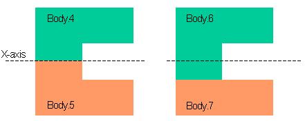
104 Page Click and select the folder in which you want to save in the IDF file. By default, the IDF file has the same name as the root product. 11. Click OK to export data to the IDF file. Your IDF file will look something like this: Discontinuity in Sections A message informs the user of discontinuities in sections of the following type: In such cases, it is recommended that two different compartments or complex compartments be created. Typical examples are given below. Bodies are then joined by renaming components in the dialog box.
105 Page 105

106 Page 106 Generating Offset Data This task shows you how to generate offset data in XML format. You can also apply different stylesheets and generate offset data in other formats, for example HTML or CSV. To do so, you must first customize your settings (Tools -> Options - > Equipment & Systems -> Structure Preliminary Layout -> Offset Data). Have a wrapping surface and appropriate sets of frame, waterline and buttock planes as well as any control curves needed. 1. Click the Offset Data icon. The Offset Data dialog box is displayed. 2. Select any Knowledgeware parameters you want in the specification tree. These parameters appear before the offset data when browsed. 3. Click the Surfaces field and select surfaces for which you want to generate the offset data. Select geometry surfaces (under the Wrapping Surface Geometry entry in the specification tree). 4. Click the Frame planes field and select frame planes of interest. 5. Click the Waterline planes field and select waterline planes of interest. 6. Click the Buttock planes field and select buttock planes of interest. 7. Click the Control curves field and select any special control lines.
107 Page 107 Multi-selection capabilities are available when selecting frame, waterline and buttock planes. 8. Click to specify your output file: The Save As dialog box appears. Identify the folder in which you want to save the file Specify a file name Select the file type: By default, only the *xml file type is available. If you checked the Apply XSL Transformation option in the Options dialog box, file types for which a stylesheet exists or has been added to the list are proposed. By default, two types are available: *.html and *.csv. Click Save. 9. Check Start browser to have your browser open automatically showing the offset results. If you set your filetype to *.html, this option is automatically checked. Ensure your browser is already open on your desktop. Using Internet Explorer 6 to browse XML files is recommended. No suitable browsers are currently available on UNIX. 10. Click OK when done. The XML file containing offset data is generated and, if you checked Start browser, your browser displays the corresponding page.

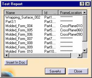
108 Page 108 Creating Reports You can generate reports that get the values of properties of objects in your documents. To do so, you must first define the report format which identifies which properties you are interested in. This report format is then used to generate reports. This task shows you how to create a report. 1. To be able to use this function, load the required knowledgeware package: Select Tools -> Options, General -> Parameters and Measure Click the Knowledge tab Check the load extended language libraries option Load the Structure Preliminary Layout package. 2. Define the report format identifying which properties you are interested in. Use Edit -> Search to select the objects for which you want to obtain a report. For more information on searching using the General, Favorites and Advanced modes, see the Infrastructure User's Guide. The 'Or' option in the Advanced mode is particularly useful for combining search criteria to select objects. 3. Generate your report based on the report format you defined. Important: Select the Currently Selected Objects option in the Generate a report dialog box. Typical Structure Preliminary Layout report:
109 Page 109
110 Page 110 Producing Lines Drawings Three different views showing the shape of a ship can be generated: Waterlines view looking down on the ship from above. Body plan showing the shapes of the frame lines. Profile view looking into the ship from the side. This tasks shows you how to generate lines drawings. Have your 3D document opened. 1.Specify your settings before you start: Select Tools ->Options ->Equipment & Systems -> Structure Preliminary Layout then the Drafting tab. 2.In addition, you will need to set the following drafting options: In the Options dialog box, select Mechanical Design ->Drafting ->View Check Project 3D wireframe, Project 3D points and Apply 3D specifications. 3.In the Structure Preliminary Layout document, select all 3D geometry and any planes to be used to generate drawings before entering the Drafting workbench. Body Plans To completely close the body plan, you must create a boundary using the Boundary command in the Generative Shape Design workbench: Activate the wrapping surface Change to the Generative Shape Design workbench Click the Boundary icon Select the wrapping surface.

111 Page Create a new drawing: Select Start -> Mechanical Design -> Drafting. You switch to the Drafting workbench and the New Drawing Creation dialog box appears. Select the view you want to create. Click OK in the New Drawing Creation dialog box. 5. Click the Front View or Advanced Front View icon. The Advanced Front View command lets you enter a name and scale. The recommended scale is 1: Return to the 3D document and select a plane of a 3D part or a plane surface to define the projection plane and the drawing view. A 3D view is previewed on your drawing. Use the drafting manipulator to adjust the view. 7.Click inside the view to generate the view.
112 Page 112 For more information on drafting capabilities, see the Drafting User's Guide.
113 Page 113 Creating Plane Systems The Plane System command provides tools letting you define a number of planes in a given direction. Planes can then be used as reference planes or supports when creating other items. In structure applications, you can, for example, define reference planes in each ship direction to assist you place structural elements. You must define one plane system for each direction. This task shows you how to create a regular asymmetric, a irregular asymmetric and a semiregular plane system. 1. Click the Plane System icon. In the Generative Shape Design workbench, this icon is to be found in the Tools toolbar. You can also select Insert -> Advanced Replication Tools -> Plane System... In the Structure Preliminary Layout workbench, this icon is to be found in the Structure Grid Set toolbar. Having selected this command, you also need to select an entry in the specification tree under which you want to create a new CATPart to locate your plane system before proceeding. If you want to use an existing CATPart, then select that CATPart in the tree. For Structure Functional Design, switch to the Generative Shape Design workbench. The Plane System dialog box appears.

114 Page Select the type of plane system you want to create: Five types are available: Regular symmetric Regular asymmetric Semi-regular Irregular symmetric Irregular asymmetric. Symmetric Plane Systems Symmetric plane systems are created in similar fashion to asymmetric plane systems. The difference being that they have the same number of planes on either side of the origin. Creating a Regular Asymmetric Plane System 3 Select a plane or a line to define the direction of the plane system. If you select a plane, the center of the plane is automatically taken as the origin of the plane system and an arrow appears showing the direction. You can, if desired, change the origin.
115 Page If you selected a line, select a point to define the origin, Or, If you selected a plane and want to change the origin, click the Origin field and select a point. Use the Reverse button in the dialog box or select the arrow in the geometry area to invert the direction. The contextual menus in Direction and Origin fields let you create appropriate geometry directly without having to exit the current command. 5.Specify the primary subset: Specify the distance between two planes in the Spacing field. Enter a prefix identifying all planes in this set. Planes are identified by this prefix plus a positive or negative number that increments away from the origin. Plane numbers are positive in the direction of the plane system. The origin is identified by prefix.0. Specify the number of planes. The number you enter is the number of planes you want to create on either side of the origin. Note that the number of planes does not include the plane at the origin. 6.(Optional) Check Allow secondary subset to group a number of planes in the primary subset together and create a secondary subset: Specify the step. For example, enter 4. Every fourth primary subset plane will belong to the secondary subset. Enter a prefix identifying all planes in this set. Notes: The plane at the origin always belongs to the primary subset. Select the subset in the specification tree to visualize all planes in this set in the geometry area. 7.Click OK when done to create a plane system along the specified direction.

116 Page 116 Creating an Irregular Asymmetric Plane System Plane systems can be created by importing a TSV (tab-separated) file containing the definition of the plane system. This file must be formatted as follows: positive_or_negative_absolute_distance_from_origin<tab>subset_prefix where <TAB> denotes a TAB character and should contain an entry 0<TAB>subset_prefix. Typically, WEB FRM FRM FRM WEB... 0 FRM WEB 2700 WEB Notes:

117 Page 117 Do not type space characters using the space bar. It is not necessary to specify the positive sign '+' when entering positive distances. It defines a plane system in one ship direction only but can contain as many subsets as desired. 3.Select a plane or a line to define the direction of the plane system. If you select a plane, the center of the plane is automatically taken as the origin of the plane system and an arrow appears showing the direction. You can, if desired, change the origin. 4.If you selected a line, select a point to define the origin, Or, If you selected a plane and want to change the origin, click the Origin field and select a point. Use the Reverse button in the dialog box or select the arrow in the geometry area to invert the direction. The contextual menus in Direction and Origin fields let you create appropriate geometry directly without having to exit the current command. 5.Click Browse... and navigate to the file containing the plane system definition. 6.Click OK when done to create a plane system along the specified direction. Creating a Semi-Regular Plane System The semi-regular option lets you easily and rapidly define a plane system comprising groups of planes with different spacings.

118 Page Select a plane or a line to define the direction of the plane system. If you select a plane, the center of the plane is automatically taken as the origin of the plane system and an arrow appears showing the direction. You can, if desired, change the origin. 4.If you selected a line, select a point to define the origin, Or, If you selected a plane and want to change the origin, click the Origin field and select a point. Use the Reverse button in the dialog box or select the arrow in the geometry area to invert the direction. The contextual menus in Direction and Origin fields let you create appropriate geometry directly without having to exit the current command.


119 Page Specify the primary subset: Specify the distance between two planes in your first group in the Spacing field. Enter the number of the last plane having the specified spacing in the End field. Click Add to confirm your first group. The first group is identified in the list view control and the Start field incremented to display the number of the first plane in your second group. Repeat to specify the spacing and the number of the last plane to be created with this spacing, then click Add. Continue until satisfied. Note: If the current spacing is the same as the spacing of the previous group, any new planes are added to the previous group. Enter a prefix identifying all planes in the primary set. Planes are identified by this prefix plus a positive or negative number that increments away from the origin. Plane numbers are positive in the direction of the plane system. The origin is identified by prefix.0. 6.(Optional) Check Allow secondary subset to group a number of planes in the primary subset together and create a secondary subset: Specify the step. For example, enter 4. Every fourth primary subset plane will belong to the secondary subset. Enter a prefix identifying all planes in this set. Notes: The plane at the origin always belongs to the primary subset. Select the subset in the specification tree to visualize all planes in this set in the geometry area. Adding Groups to Your Plane System Click in the list view control to return to the Add mode.
120 Page 120 Modifying Groups in Your Plane System Select the group you want to modify. Enter a new spacing value or modify the End value to change the number of planes in the group. Note: You cannot modify the Start value. Click Modify. The plane system is updated. Changing the number of planes in any one group does not affect the number of planes in other groups. Note: Click in the list view control to cancel unwanted modifications that have not been confirmed using Modify. Removing Groups Select the group you want to remove. Click Remove. 7.Click OK when done to create a plane system along the specified direction.
121 Page 121 Managing Your Project Working with a Cache System Managing Ship Project Data Understanding Project Resource Management About the Feature Dictionary About Object Naming Rules
122 Page 122 Working with a Cache System To improve system performance when working with very large documents, it is recommended that you activate the cache. This recommendation is valid when working in file-based mode as well as with ENOVIA LCA. This means that documents will be loaded in visualization mode, however, when editing structural items such as stiffeners or molded forms, the item is automatically switched to design mode. Any entities used to define the item you want to edit are also switched to design mode. Any new structures are created in design mode in the document. The cache system is managed via the Cache Management tab in the Options dialog box (Tools -> Options -> Infrastructure -> Product Structure). For more information see Customizing Cache Settings in the Customizing section of the Infrastructure User's Guide.
123 Page 123 Managing Ship Project Data Proper management of project data offers the following advantages: Clear and user-friendly organization of data Easy location of items in the specification tree Facilitates management of Hide / Show capabilities for CATParts and CATProducts. This task recommends a way to manage project data that offers the above advantages. The corresponding specification tree looks like this: 1. Enter the Structure Preliminary Layout workbench (Start -> Equipment & Systems - > Structure Preliminary Layout). 2. Add the Structure Preliminary Layout level to the specification tree: Right-click the root product and select Components -> New Component from the contextual menu In the Part Number dialog box that appears, enter Structure Preliminary Layout, then click OK.
124 Page Create a wrapping surface under Structure Preliminary Layout using the Wrapping Surface command. Note: Double-click Structure Preliminary Layout to activate this level. 4. Right-click and select Components -> Existing Component... to insert CATParts containing pre-defined reference planes, typically Deck_Reference_Planes, Long_Reference_Planes and Cross_Reference_Planes. Note: It is recommended that one CATPart contain the set of reference planes in one ship direction only. 5. Right-click and select Components -> New Component from the contextual menu to create other levels as follows: Decks Transversal_Blk Longitudinal_Blk Unspecified_Blk Preliminary_Openings Basis_Bounded_Zones Composite_Bounded_Zones 6. You are now ready to start you preliminary design. You can also add the Structure Functional Design level to the specification tree and apply the same approach when managing functional design data.
125 Understanding Project Resource Management Page 125 Project resources are managed by system administrators. Typically this involves entering information such as folder paths for resources, like user dictionaries such as the feature dictionary, without which the application cannot function. What administrators enter will be visible in the Browse tab of the Project Resource Management dialog box (Tools -> Project Management), but it cannot be changed there. A sample project resource management file is provided with this application and by default, the application will start with this file. The following Structure Preliminary Layout-related resources are managed in this file. Project Resources Feature dictionary managing object classes Discrete values for attributes ID schema managing object naming rules ID sequence number directory: contains the last sequence number that was generated for an object. Parts catalog. Structure Discipline Resources Orientation naming conventions: contains naming conventions for ship directions. Default conventions are USA conventions listed in sample CATStrOrientNamingUSAConv. A sample file for European conventions is also supplied: CATStrOrientNamingEURConv. The default location for these resources is downloaddirectory/os/resources/msgcatalog, where OS is the operating system, for example intel_a (Windows NT). Structure Preliminary Layout Application Resources Project name specifying the current project name. DS Default, by default. Project bounding box: defines overall project dimensions. Default dimensions (mm) are: X+ X- Y+ Y- Z+ Z The center of the box is positioned at the center of the document. Note that when the user creates the wrapping surface, the bounding box is automatically re-dimensioned to include the hull form. If there is more than one project at your site, then a project resource management file is made for each project. You can open another resource management file using the Project Management command (Tools -> Project Management). For more information on how to do so, see Using the PRM command in the Infrastructure User's Guide. For more information on resources and how the resource management file is organized, see Understanding Project Resource Management. Managing project resources is typically performed by an administrator.
 and a number of sub-classes are")

126 About the Feature Dictionary Page 126 The feature dictionary manages object classes. In the sample dictionary provided with the application, three main object classes (wrapping surface, molded form, and bounded zone or compartment) and a number of sub-classes are managed. Note: In the application, these object classes are managed via the class browser. To view the sample dictionary: 1.Open the CATStrPreliminaryLayoutSample.CATfct file. By default, this file is located in the install_folder under /resources/graphic. The Feature Dictionary Editor opens showing the sample dictionary. The Classes View displays all the classes available in the document, i.e. the predefined classes included in the application.

127 Page Double-click Bounded Zone (corresponds to compartment) to view associated class attributes. Existing attributes or properties are displayed in the Inherited attributes and Local attributes boxes. Inherited attributes are those inherited from the super class to which this class belongs. Local attributes are properties added to the class itself. The following table lists the object classes and corresponding attributes provided in the sample dictionary. Wrapping Surface Type Molded Form BulkheadIntegrity FrameLocation InsulationTreatments PaintSchedule SurfaceTreatments Tightness Bounded Zone or Compartment FunctionNumber HVACCategory Location PaintThickness Attributes or properties assigned to object classes can be browsed via the Properties dialog box (right-click feature in specification tree and select Properties from the contextual menu). You can add sub-classes and attributes to the sample dictionary, or if you want, you can create a new feature dictionary. You may, for example, want to create several sub-classes under wrapping surface in the sample dictionary for deckhouses, internal and external wrapping surfaces. You can also define or modify object naming rules using the Define ID Schema icon in the Feature Dictionary Editor workbench. For more information, see Using the Feature Dictionary Editor in the Infrastructure User's Guide.
128 Page 128 About Object Naming Rules Structure Preliminary Layout provides a set of default naming rules or unique identifiers for the objects you create. This identifier consists of a prefix that identifies the type of object it is, followed by a unique number. You may want to modify these rules to suit your own requirements: For objects integrated into the feature dictionary, use the Define/Modify ID Schema command in the Feature Dictionary Editor application. For all other objects, you must edit XML files directly. By default, sample XML files are located in the install_folder under startup/equipmentandsystems/structurepreliminarylayout/datadictionary. Modifying or defining object naming rules is typically performed by an administrator. For more information, see Modifying the Object Naming Rules in the Infrastructure User's Guide.

129 Page 129 Structure Preliminary Layout Package in Knowledge Expert A Structure Preliminary Layout package is supported by Knowledge Expert. This package can be accessed via the object browser and objects, attributes and methods in the package used in expert relations. You can, for example, write a rule to change the color of all molded forms of a given type. The package contains the following main objects: CATSPLBooleanOperator CATSPLBoundedZone CATSPLWrappingSurf CATSPLMoldedForm. All other objects listed in the browser derive from the above main objects, for example Deck derives from CATSPLMoldedForm. These objects or sub-classes are managed in the sample feature dictionary. For information on object attributes and methods, see Structure Preliminary Layout in the Reference Information section of the Knowledge Expert User's Guide.
130 Page 130 Interoperability Working with ENOVIA LCA: Optimal CATIA PLM Usability Taking Advantage of ENOVIA LCA Capabilities Working with SmarTeam
131 Page 131 Working with ENOVIA LCA: Optimal CATIA PLM Usability When working with ENOVIA LCA, Optimal CATIA PLM Usability ensures that you only create and edit data in CATIA that can be correctly saved in ENOVIA. ENOVIA LCA offers two different storage modes: Workpackage (Document kept - Publications Exposed) and Explode (Document not kept). In Structure Preliminary Layout, data is saved correctly in ENOVIA LCA in both modes, however, Explode mode is the recommended mode since this mode lets you manage Structure Preliminary Layout objects individually in ENOVIA. All Structure Preliminary commands are thus available at all times. Recommended Methodology The recommended methodology for working with ENOVIA LCA is: Create a product class root (PRC) and product in ENOVIA LCA. Send your ENOVIA document to CATIA. Work on your design in CATIA, whether from scratch or modifying an existing design. Save your CATIA data in ENOVIA. To ensure seamless integration, you must have both a CATIA and ENOVIA session running. 1. In the Product Structure workbench of CATIA V5, click the Init Enovia V5 Connection... icon to establish the connection between CATIA V5 and ENOVIA LCA. 2. In ENOVIA LCA, send your ENOVIA document to CATIA. 3. Work on your design in your CATIA V5 application. 4. In the Product Structure workbench of CATIA V5, click the Save Data in ENOVIA V5 Server... icon to save your CATIA data in ENOVIA. The Save in ENOVIA V5 dialog box appears showing objects to be saved and set to the correct save mode and save options. All structural items created under the root and any new components are saved in
132 Page 132 Explode mode; new products are saved in Workpackage mode. 5. Simply click OK in the dialog box. If the CATIA document root is not an ENOVIA document: Save your work temporarily Create a product class root (PRC) and product in ENOVIA Send the ENOVIA document to CATIA Insert the components (Insert -> Existing Component) containing the work you saved temporarily above Save your work in ENOVIA. For more information, see the CATIA / ENOVIA Interoperability User's Guide.
133 Page 133 Taking Advantage of ENOVIA LCA Capabilities To assist you in your structure preliminary layout, ENOVIA LCA provides capabilities letting you manage multiple design options and run compartment queries for application objects stored in the ENOVIA LCA database. Multiple Design Options Managing multiple design options corresponds to the ENOVIA LCA capability of managing part versions. The recommended methodology to do so is: Work on your new design option in CATIA. Create a new part version in ENOVIA: You should create as many part versions as different design options. Attach the CATIA document to the part version. For more information, see Manage Part Versions in the ENOVIA LifeCycle Applications Engineering LifeCycle guide. Querying for Compartments The ENOVIA LCA Search Tree enables you to query the ENOVIA LCA database for compartments by type. For more information, see Manage Searches in the ENOVIA LifeCycle Applications Engineering LifeCycle guide.

134 Page 134 Working with SmarTeam Structure Preliminary Layout documents can be stored in SmarTeam. Documents are managed in projects in SmarTeam. You must therefore create a SmarTeam project. To ensure seamless integration, you must have both a CATIA and SmarTeam session running. 1. In CATIA, specify your document environment: Select Tools -> Options -> General -> Documents tab Set SmarTeam to Allowed. 2. Still in CATIA, select Connect from the SmarTeam menu to establish your CATIA - SmarTeam connection. 3. To save a CATIA document in SmarTeam: Select Save from the SmarTeam menu. The Projects Manager dialog box displays. Search for the SmarTeam project you want to save your document under. Select the project Select the Link to Projects checkbox, then click Save. Your document is saved in SmarTeam.

135 Page To open a SmarTeam document and send it to CATIA: Select Find Document from the SmarTeam menu in CATIA. The Search Editor dialog box displays. Select CATIA Products, then click Run. The CATIA Products dialog box displays. Right-click the project and select File Operation -> Open in the contextual menu. The document associated with the SmarTeam project opens in CATIA. For more information on SmarTeam capabilities, see the appropriate guide.

136 Workbench Description Page 136 The Structure Preliminary Layout Version 5 application window looks like this: Click the hotspots to see related documentation. Structure Preliminary Layout Toolbar Structure Grid Set Toolbar Specification Tree
137 Page 137 Structure Preliminary Layout Toolbar See Browsing project data See Wrapping surfaces See Creating simple molded forms See Creating multiple molded forms See Creating external molded forms See Openings See Creating compartments See Creating complex compartments See Creating boundaries See Modifying boundary user type See Exporting data in IDF format See Generating offset data
138 Page 138 Structure Grid Set Toolbar See Defining reference planes

139 Page 139 Specification Tree Icons displayed in the specification tree and specific to Structure Preliminary Layout workbench identify: Wrapping surface Molded form Opening Bounded zone Composite volume For other symbols used in the specification tree, see Specification Tree Symbols.
140 Page 140 Customizing Structure Preliminary Layout Before you start your first session, you can customize the way you work to suit your habits. This type of customization is stored in permanent setting files: these settings will not be lost if you end your session. 1. Select the Tools -> Options command. The Options dialog box displays. 2. Select the Equipment & Systems category in the left-hand box. 3. Click the Structure Preliminary Layout sub-category. The Design, Drafting and Offset Data tabs display. The Design tab lets you set default colors for main items. The Drafting tab lets you customize lines drawings. The Offset Data tab lets you manage the output formats for your offset data. One other setting, Keep link with seleted object, is also needed to ensure associativity between the items you create and entities selected to create them. 4. Select Infrastructure -> Part Infrastructure -> General, then select Keep link with selected object. 5. Set options in these tabs according to your needs. 6. Click OK in the Options dialog box when done.
141 Page 141 Design Settings The Design tab contains one category of options: Default colors. Default Colors Use the color chooser to define the default color for molded forms, bounded zones (compartments) and boundaries. By default, colors are as shown above.
142 Page 142 Drafting The Drafting tab contains five categories of options letting you customize your lines drawings: Geometry to display Waterlines view Waterline position Body plan Midship position Geometry to Display Select the option defining how the shape of the ship is shown on lines drawings: Wireframe only or Surface only, or Both. By default, the option is Wireframe only. For a body plan, ensure Wireframe only is checked. Waterlines View Select the option defining the view looking at the ship from above: Symmetrical or Asymmetrical depending on whether or not the ship is symmetrical about the centerline. This generates a halfbreadth or full-breadth view respectively. Typical half-breadth view:
143 Page 143 By default, the option is Asymmetrical. Waterline Position Select WaterLine reference plane If this option is selected, the waterline is located at the selected reference plane in the 3D document. Specify value (absolute z coordinates) If this option is selected, the waterline is located along the Z direction at the absolute coordinate entered in the Absolute Z coordinate box. By default, the option is Specify value. Body Plan Select the option defining the view showing the shapes of the frame lines: Symmetrical or Asymmetrical depending on whether or not the ship is symmetrical about the centerline. The generated view is made of two parts. If the ship is symmetrical, only one side of the ship is shown (usually the portside) and the right-hand part looks aft at the forward portside of the ship, while the left-hand part looks forward at the after half of the portside. If the ship is asymmetrical, both sides of the ship are shown. Typical body plan:

144 Page 144 To generate this drawing, you need to define the midship position (see below). By default, the option is Asymmetrical. Midship Position Select middle station If this option is selected, the midship is located at the selected reference plane in the 3D document. Specify value (absolute xcoordinates) If this option is selected, the midship is located along the X direction at the absolute coordinate entered in the Absolute X coordinate box. By default, the option is Specify value.
145 Page 145 For the options in this tab page to be taken into account, you need to select Project 3D wireframe, Project 3D points and Apply 3D specifications located in Mechanical Design - > Drafting -> View -> Geometry generation/dress-up frame. By default, Project 3D wireframe and Project 3D points are cleared, and Apply 3D specifications is selected.

146 Page 146 Offset Data The Offset Data tab contains one category of options to manage output formats, for example HTML pages or CSV files, for your offset data: Global. Global New / Edit / Delete Use New, Edit or Delete to add new stylesheets, and edit or delete existing ones. Sample stylesheets (OffsetDataAsHTML.xls and OffsetDataAsCSV.xls) for two formats, HTML and CSV respectively, are provided. By default, they are located in the installation folder under OS/startup/EquipmentAndSystems/StructurePreliminaryLayout/StyleSheet. Apply XSL Transformation Select this option to take all stylesheets into account and choose the format of your output data when interactively generating your offset data. By default, this option is cleared and only XML files will be generated.
Structure Preliminary Layout
 Structure Preliminary Layout Overview Conventions What's New? Getting Started Setting Up Your Session Defining the Hull Form Setting Up Your Grid Creating Molded Forms Creating a Compartment Creating Boundaries
Equipment Support Structures
 Page 1 Equipment Support Structures Preface Using This Guide Where to Find More Information Conventions What's New? Getting Started Setting Up Your Session Creating a Simple Structural Frame Creating Non-uniform
Equipment Support Structures
 Equipment Support Structures Overview Conventions What's New? Getting Started Setting Up Your Session Creating a Simple Structural Frame Creating Non-uniform Columns Creating Plates with Openings Bracing
Compartment and Access
 Compartment and Access Page 1 Preface Using This Guide What's New? Getting Started Entering the Workbench Set Correct Working Units and Grid Saving Documents User Tasks Creating/Modifying Wall Systems
Compartment and Access
 Compartment and Access Preface Using This Guide What's New? Getting Started Entering the Workbench Set Correct Working Units and Grid Saving Documents User Tasks Creating/Modifying Wall Systems Building
DMU Space Engineering Assistant User Guide
 DMU Space Engineering Assistant User Guide Overview Conventions What's New? Getting Started User Tasks Setting Up Your Session Running an Interference Analysis Workbench Description DMU Space Engineering
DMU Space Analysis Version 5 Release 13. DMU Space Analysis
 Page 1 DMU Space Analysis Preface Using This Guide More Information Conventions What's New? Getting Started Setting Up Your Session Measuring Minimum Distances Sectioning Detecting Clashes Measuring Between
Electrical Harness Flattening
 Electrical Harness Flattening Overview Conventions What's New? Getting Started Accessing the Electrical Harness Flattening Workbench Defining the Harness Flattening Parameters Extracting Data Flattening
DMU Space Engineering Assistant User Guide
 Page 1 DMU Space Engineering Assistant User Guide Overview Conventions What's New? Getting Started User Tasks Setting Up Your Session Running a Interference Workbench Description DMU Space Engineering
Circuit Board Design Version 5 Release 13. Circuit Board Design
 Circuit Board Design Page 1 Overview Conventions What's New? Getting Started Accessing the Circuit Board Workbench Creating a Board Pocket and Holes Constraint Area Exporting Data Importing Data User Tasks
Piping & Instrumentation Diagrams
 Piping & Instrumentation Diagrams Preface Using This Guide What's New? Getting Started Entering the Workbench Setting up Working Units and Grid Placing Components Routing a Piping Line or I & C Loop Placing
Electrical 3D Design & Documentation
 Electrical 3D Design & Documentation Page 1 Overview Conventions User Tasks Using Electrical 3D Design & Documentation Entering the Electrical Assembly Design Workbench Entering the Electrical Part Design
Electrical Harness Installation
 Electrical Harness Installation Page 1 Overview Conventions What's New? Getting Started Entering the Workbench Setting Up the Options Creating a Bundle Segment Document Creating Construction Points Defining
Solidworks 2006 Surface-modeling
 Solidworks 2006 Surface-modeling (Tutorial 2-Mouse) Surface-modeling Solid-modeling A- 1 Assembly Design Design with a Master Model Surface-modeling Tutorial 2A Import 2D outline drawing into Solidworks2006
Piping & Instrumentation Diagrams
 Page 1 Piping & Instrumentation Diagrams Preface Using This Guide What's New? Getting Started Entering the Workbench Setting up Working Units and Grid Placing Components Routing a Piping Line or I & C
Electrical Wire Routing
 Electrical Wire Routing Page 1 Overview Conventions What's New? Getting Started Accessing the Workbench Creating the Bundle Selecting Systems with External Data Routing Wires from External Data User Tasks
HVAC Diagrams Preface What's New? Getting Started User Tasks
 HVAC Diagrams Preface Using This Guide What's New? Getting Started Entering the Workbench Setting up Working Units and Grid Placing Components Routing an HVAC Line Placing Components in a Line Repositioning
Fastening Review Overview Basic Tasks DMU Fastening Review Interoperability Workbench Description Customizing Index
 Fastening Review Overview Conventions Basic Tasks Displaying Joined Parts in a Balloon Running the Fastening Rules Analysis Reporting Creating Structural Reports Creating Flat Reports DMU Fastening Review
Advanced Meshing Tools
 Page 1 Advanced Meshing Tools Preface Using This Guide More Information Conventions What's New? Getting Started Entering the Advanced Meshing Tools Workbench Defining the Surface Mesh Parameters Setting
DMU Engineering Analysis Review
 Page 1 DMU Engineering Analysis Review Preface Using This Guide Where to Find More Information Conventions What's New? Getting Started Inserting a CATAnalysis Document Using DMU Space Analysis From CATAnalysis
FreeStyle Shaper & Optimizer
 FreeStyle Shaper & Optimizer Preface What's New Getting Started Basic Tasks Advanced Tasks Workbench Description Customizing Glossary Index Dassault Systèmes 1994-99. All rights reserved. Preface CATIA
CATIA Surface Design
 CATIA V5 Training Exercises CATIA Surface Design Version 5 Release 19 September 2008 EDU_CAT_EN_GS1_FX_V5R19 Table of Contents (1/2) Creating Wireframe Geometry: Recap Exercises 4 Creating Wireframe Geometry:
Preface. Version 5 Release 5. Mold Tooling Design
 Version 5 Release 5 Mold Tooling Design Preface Getting Started Basic Tasks Advanced Tasks Customization Workbench Description Glossary Index Preface The CATIA Version 5 Mold Tooling Design application
DMU Engineering Analysis Review
 DMU Engineering Analysis Review Overview Conventions What's New? Getting Started Entering DMU Engineering Analysis Review Workbench Generating an Image Visualizing Extrema Generating a Basic Analysis Report
Electrical System Functional Definition
 Electrical System Functional Definition Preface What's New? Getting Started Basic Tasks Advanced Tasks Workbench Description Customizing Glossary Index Dassault Systèmes 1994-2000. All rights reserved.
Mechanical Design V5R19 Update
 CATIA V5 Training Foils Mechanical Design V5R19 Update Version 5 Release 19 August 2008 EDU_CAT_EN_MD2_UF_V5R19 1 About this course Objectives of the course Upon completion of this course you will be able
Systems Space Reservation
 Systems Space Reservation Preface Using This Guide What's New? Getting Started Enter the Workbench Create an Equipment Reservation Set Correct Working Units and Grid Changing the Current Axis Saving Documents
FreeStyle Shaper Optimizer & Profiler
 FreeStyle Shaper Optimizer & Profiler Page 1 Preface Using This Guide More Information What's New? Getting Started Starting the FreeStyle Workbench Creating a First Surface Editing the Surface Creating
Additional Exercises. You will perform the following exercises to practice the concepts learnt in this course:
 Additional Exercises You will perform the following exercises to practice the concepts learnt in this course: Master Exercise : Mobile Phone Plastic Bottle Exercise 1 Master Exercise : Mobile Phone In
Electrical System Functional Definition
 Electrical System Functional Definition Overview Conventions What's New? Getting Started Creating a New System Creating Equipment Creating Connectors Creating a Signal Connecting Saving Your System User
Piping Design. Site Map Preface Getting Started Basic Tasks Advanced Tasks Customizing Workbench Description Index
 Piping Design Site Map Preface Getting Started Basic Tasks Advanced Tasks Customizing Workbench Description Index Dassault Systèmes 1994-2001. All rights reserved. Site Map Piping Design member member
Electrical Library Version 5 Release 13. Electrical Library
 Electrical Library Page 1 Overview Conventions What's New? Getting Started Entering the Electrical Part Design Workbench Defining a Single Insert Connector Defining a Cavity Connection Point Entering Electrical
Lesson 3: Surface Creation
 Lesson 3: Surface Creation In this lesson, you will learn how to create surfaces from wireframes. Lesson Contents: Case Study: Surface Creation Design Intent Stages in the Process Choice of Surface Sweeping
Product Structure Version 5 Release 13. Product Structure
 Product Structure Page 1 Site Map Preface Conventions What's New? Basic Tasks Entering the Product Structure Workbench Opening a CATProduct with a Progress Bar Selecting Products only Selecting Modes Inserting
Additional Surface Tools
 Additional Surface Tools Several additional surface tools, techniques, and related functions are available. This supplement provides a brief introduction to those functions. Panel Part Features Replace
Aerospace Sheetmetal Design
 Aerospace Sheetmetal Design Page 1 Overview Conventions What's New? Getting Started Entering the Aerospace SheetMetal Design Workbench Defining the Aerospace SheetMetal Parameters Creating a Web from a
Prismatic Machining Overview What's New Getting Started User Tasks
 Prismatic Machining Overview Conventions What's New Getting Started Enter the Workbench Create a Pocketing Operation Replay the Toolpath Create a Profile Contouring Operation Create a Drilling Operation
Knowledge Advisor Overview What's New? Getting Started User Tasks
 Knowledge Advisor Overview Conventions What's New? Getting Started Using Parameters Using Formulas Using Rules Using Checks User Tasks Working with Parameters Creating a Parameter Introducing Parameters
Tolerance Analysis of Deformable Assembly
 Tolerance Analysis of Deformable Assembly Overview Conventions What's New? Getting Started Entering the Workbench Creating a New Analysis Importing the Assembly Definition Computing a Tolerance Analysis
Education Curriculum Surface Design Specialist
 Education Curriculum Surface Design Specialist Invest your time in imagining next generation designs. Here s what we will teach you to give shape to your imagination. CATIA Surface Design Specialist CATIA
Lesson 6: Work in Multi-Model Environment with Surface
 Lesson 6: Work in Multi-Model Environment with Surface In this lesson, you will learn how to work in Multi-Model Environment with Surface. Lesson Contents: Case Study: Multi-Model Environment with Surface
NC Manufacturing Verification
 NC Manufacturing Verification Overview Conventions What's New? User Tasks Accessing NC Manufacturing Verification Comparing the Machined Stock Part and the Design Part Pick Point Analysis in Video Mode
SheetMetal Design Version 5 Release 13. SheetMetal Design
 SheetMetal Design Page 1 Overview Conventions What's New? Getting Started Entering the Workbench Defining the Parameters Creating the First Wall Creating the Side Walls Creating a Cutout Creating Automatic
DMU Fitting Simulator
 Page 1 DMU Fitting Simulator Preface Using This Guide More Information Conventions What's New? Getting Started Using Tracks Starting a Session Recording a Track Using Automatic Path Finder Using the Smooth
Revit Architecture 2015 Basics
 Revit Architecture 2015 Basics From the Ground Up Elise Moss Authorized Author SDC P U B L I C AT I O N S Better Textbooks. Lower Prices. www.sdcpublications.com Powered by TCPDF (www.tcpdf.org) Visit
NC Manufacturing Verification
 NC Manufacturing Verification Page 1 Preface Using This Guide Where to Find More Information Conventions What's New? User Tasks Accessing NC Manufacturing Verification Comparing the Machined Stock Part
Autodesk Inventor Design Exercise 2: F1 Team Challenge Car Developed by Tim Varner Synergis Technologies
 Autodesk Inventor Design Exercise 2: F1 Team Challenge Car Developed by Tim Varner Synergis Technologies Tim Varner - 2004 The Inventor User Interface Command Panel Lists the commands that are currently
Structure Design Administration
 CATIA V5 Training Exercises Structure Design Administration Version 5 Release 19 January 2009 EDU_CAT_EN_SRA_AX_V5R19 1 Table of Contents Step 1: Creating a New Project 3 Do It Yourself 4 Step 2: Adding
Parametric Modeling. With. Autodesk Inventor. Randy H. Shih. Oregon Institute of Technology SDC PUBLICATIONS
 Parametric Modeling With Autodesk Inventor R10 Randy H. Shih Oregon Institute of Technology SDC PUBLICATIONS Schroff Development Corporation www.schroff.com www.schroff-europe.com 2-1 Chapter 2 Parametric
Knowledge Expert Overview What's New? Getting Started Basic Tasks Advanced Tasks Reference
 Knowledge Expert Overview Conventions What's New? Getting Started Creating an Expert Check Creating an Expert Rule Basic Tasks About RuleBases Storing a Rule Base in a Catalog Using a Rule Base Stored
Generative Shape Design
 Generative Shape Design Copyright DASSAULT SYSTEMES 2002 1 Exercise 60 min. The Knob In this exercise you will have the opportunity to model an appliance Knob starting from an empty model. You will create
Electrical Cableway Routing
 Electrical Cableway Routing Preface Using This Guide What's New? Getting Started Entering the Workbench Placing a Hanger Routing a Loft Through Hangers Placing a Conduit on a Run Saving Documents Updating
DMU Optimizer Overview What's New? Getting Started User Tasks
 DMU Optimizer Overview Conventions What's New? Getting Started Starting a Session Generating a Silhouette Generating a Wrapping Generating a Thickness Generating an Offset Generating a Free Space User
FEM Surface. Preface Getting Started Basic Tasks Glossary Index TOC. Dassault Systèmes All rights reserved.
 TOC FEM Surface Preface Getting Started Basic Tasks Glossary Index Dassault Systèmes 1994-99. All rights reserved. file:////moyenne/users/cma/fmsdoccxr5/fmsenglish/fmsug.doc/src/fmsugtoc.htm [09/26/2000
Tutorial Second Level
 AutoCAD 2018 Tutorial Second Level 3D Modeling Randy H. Shih SDC PUBLICATIONS Better Textbooks. Lower Prices. www.sdcpublications.com Powered by TCPDF (www.tcpdf.org) Visit the following websites to learn
Parametric Modeling with UGS NX 4
 Parametric Modeling with UGS NX 4 Randy H. Shih Oregon Institute of Technology SDC PUBLICATIONS Schroff Development Corporation www.schroff.com www.schroff-europe.com 2-1 Chapter 2 Parametric Modeling
Lesson 1 Parametric Modeling Fundamentals
 1-1 Lesson 1 Parametric Modeling Fundamentals Create Simple Parametric Models. Understand the Basic Parametric Modeling Process. Create and Profile Rough Sketches. Understand the "Shape before size" approach.
CATIA V5 Parametric Surface Modeling
 CATIA V5 Parametric Surface Modeling Version 5 Release 16 A- 1 Toolbars in A B A. Wireframe: Create 3D curves / lines/ points/ plane B. Surfaces: Create surfaces C. Operations: Join surfaces, Split & Trim
TRAINING SESSION Q2 2016
 There are 8 main topics in this training session which focus on the Sketch tools in IRONCAD. Content Sketch... 2 3D Scene Background Settings... 3 Creating a new empty Sketch... 4 Foam with cut out for
Shape Sculptor Version 5 Release 13. Shape Sculptor
 Shape Sculptor Page 1 Overview Using This Guide Where to Find More Information What's New? Getting Started Entering the Workbench Importing a Polygonal Mesh Decimating a Polygonal Mesh User Tasks Input
Lesson 4: Surface Re-limitation and Connection
 Lesson 4: Surface Re-limitation and Connection In this lesson you will learn how to limit the surfaces and form connection between the surfaces. Lesson contents: Case Study: Surface Re-limitation and Connection
Knowledge Expert Version 5 Release 13. Knowledge Expert
 Knowledge Expert Page 1 Preface Using this Guide What's New? Getting Started Basic Tasks About RuleBases Storing a Rule Base in a Catalog Using a Rule Base Stored in a Catalog Importing a Rule Base Activating
Inventor. Additional Surface Tools. Replacing Faces
 Additional Surface Tools Inventor includes several additional surface tools, techniques, and related functions. Surface tools are appropriate for some basic applications, and are commonly used when other
SolidWorks Implementation Guides. User Interface
 SolidWorks Implementation Guides User Interface Since most 2D CAD and SolidWorks are applications in the Microsoft Windows environment, tool buttons, toolbars, and the general appearance of the windows
Chapter 2 Parametric Modeling Fundamentals
 2-1 Chapter 2 Parametric Modeling Fundamentals Create Simple Extruded Solid Models Understand the Basic Parametric Modeling Procedure Create 2-D Sketches Understand the "Shape before Size" Approach Use
Module 1: Basics of Solids Modeling with SolidWorks
 Module 1: Basics of Solids Modeling with SolidWorks Introduction SolidWorks is the state of the art in computer-aided design (CAD). SolidWorks represents an object in a virtual environment just as it exists
Create Complex Surfaces
 Create Complex Surfaces In this lesson, you will be introduced to the functionalities available in the Generative Surface Design workbench. Lesson content: Case Study: Surface Design Design Intent Stages
Chapter 16: Boat Hull - Loft and Sweep
 This tutorial demonstrates classic boat hull lofting techniques using typical plan and profile curves. The classic hull shape is based on a design from an old Boat Builder s Handbook magazine. Many designs
전산응용설계 (Computer Aided Design)
") 전산응용설계 (Computer Aided Design) CATIA (Computer Aided Three dimensional Interactive Application) 기계자동차공학부자동차공학전공 Chapter 3. CATIA 기초 학습내용 : 객체선택 (Selecting Objects) 객체감추기와보이기 (Hiding and Showing objects)
전산응용설계 (Computer Aided Design) CATIA (Computer Aided Three dimensional Interactive Application) 기계자동차공학부자동차공학전공 Chapter 3. CATIA 기초 학습내용 : 객체선택 (Selecting Objects) 객체감추기와보이기 (Hiding and Showing objects)
Appendix B: Creating and Analyzing a Simple Model in Abaqus/CAE
 Getting Started with Abaqus: Interactive Edition Appendix B: Creating and Analyzing a Simple Model in Abaqus/CAE The following section is a basic tutorial for the experienced Abaqus user. It leads you
Quick Tips to Using I-DEAS. Learn about:
 Learn about: Quick Tips to Using I-DEAS I-DEAS Tutorials: Fundamental Skills windows mouse buttons applications and tasks menus icons part modeling viewing selecting data management using the online tutorials
Feature-Based Modeling and Optional Advanced Modeling. ENGR 1182 SolidWorks 05
 Feature-Based Modeling and Optional Advanced Modeling ENGR 1182 SolidWorks 05 Today s Objectives Feature-Based Modeling (comprised of 2 sections as shown below) 1. Breaking it down into features Creating
Parametric Modeling. with. Autodesk Inventor Randy H. Shih. Oregon Institute of Technology SDC
 Parametric Modeling with Autodesk Inventor 2009 Randy H. Shih Oregon Institute of Technology SDC PUBLICATIONS Schroff Development Corporation www.schroff.com Better Textbooks. Lower Prices. 2-1 Chapter
1 awea.com.m y
 1 www.mawea.com.m y 2 www.mawea.com.m y Announcement (1.0) (1.1) LUM END of Support The support of LUM licensing technology was end on December 31 st 2013. This technology had been replaced by DSLS which
Chapter 2 Parametric Modeling Fundamentals
 2-1 Chapter 2 Parametric Modeling Fundamentals Create Simple Extruded Solid Models Understand the Basic Parametric Modeling Procedure Create 2-D Sketches Understand the Shape before Size Approach Use the
Selective Space Structures Manual
 Selective Space Structures Manual February 2017 CONTENTS 1 Contents 1 Overview and Concept 4 1.1 General Concept........................... 4 1.2 Modules................................ 6 2 The 3S Generator
CATIA V5-6R2015 Product Enhancement Overview
 Click to edit Master title style CATIA V5-6R2015 Product Enhancement Overview John Montoya, PLM Technical Support March 2015 1 2010 Inceptra LLC. All rights reserved. Overview of Enhanced Products Overview
Chapter 4 Feature Design Tree
 4-1 Chapter 4 Feature Design Tree Understand Feature Interactions Use the FeatureManager Design Tree Modify and Update Feature Dimensions Perform History-Based Part Modifications Change the Names of Created
Finite Element Course ANSYS Mechanical Tutorial Tutorial 3 Cantilever Beam
 Problem Specification Finite Element Course ANSYS Mechanical Tutorial Tutorial 3 Cantilever Beam Consider the beam in the figure below. It is clamped on the left side and has a point force of 8kN acting
Autodesk Fusion 360: Model. Overview. Modeling techniques in Fusion 360
 Overview Modeling techniques in Fusion 360 Modeling in Fusion 360 is quite a different experience from how you would model in conventional history-based CAD software. Some users have expressed that it
The ultimate approach for General Arrangement Definition
 The ultimate approach for General Arrangement Definition Rodrigo Perez (M) and Veronica Alonso 1 1. SENER, Madrid/Spain General Arrangement Drawing is a communication language that uses graphics to represent
Technique or Feature Where Introduced
 Part 6: Keypad 4 Mirrored features Patterned features First extrusion Rounded corners In the earpiece part, you defined a radial pattern, one that created new instances of a feature at intervals around
Elise Moss Revit Architecture 2017 Basics From the Ground Up SDC. Better Textbooks. Lower Prices.
 Elise Moss Revit Architecture 2017 Basics From the Ground Up SDC P U B L I C AT I O N S Better Textbooks. Lower Prices. www.sdcpublications.com Powered by TCPDF (www.tcpdf.org) Visit the following websites
Solid Bodies and Disjointed Bodies
 Solid Bodies and Disjointed Bodies Generally speaking when modelling in Solid Works each Part file will contain single solid object. As you are modelling, each feature is merged or joined to the previous
Exercise Guide. Published: August MecSoft Corpotation
 VisualCAD Exercise Guide Published: August 2018 MecSoft Corpotation Copyright 1998-2018 VisualCAD 2018 Exercise Guide by Mecsoft Corporation User Notes: Contents 2 Table of Contents About this Guide 4
Changes from SolidWorks 2003 to SolidWorks 2004
 Changes from SolidWorks 2003 to SolidWorks 2004 The changes from SolidWorks 2003 to SolidWorks 2004 are primarily cosmetic. Consequently, it is quite easy to use the current edition of Learning SolidWorks
An Introduction to Autodesk Inventor 2010 and AutoCAD Randy H. Shih SDC PUBLICATIONS. Schroff Development Corporation
 An Introduction to Autodesk Inventor 2010 and AutoCAD 2010 Randy H. Shih SDC PUBLICATIONS Schroff Development Corporation www.schroff.com 2-1 Chapter 2 Parametric Modeling Fundamentals Create Simple Extruded
Learning the Pro/ENGINEER Interface
 2 Learning the Pro/ENGINEER Interface This chapter introduces the Pro/ENGINEER interface tools: the menus, the dashboards, the selection tools and the viewing controls. As you go through this chapter,
STL Rapid Prototyping
 CATIA V5 Training Foils STL Rapid Prototyping Version 5 Release 19 January 2009 EDU_CAT_EN_STL_FI_V5R19 1 About this course Objectives of the course Upon completion of this course you will learn how to
Inventor 201. Work Planes, Features & Constraints: Advanced part features and constraints
 Work Planes, Features & Constraints: 1. Select the Work Plane feature tool, move the cursor to the rim of the base so that inside and outside edges are highlighted and click once on the bottom rim of the
Project 3. Top Down Design In Context. Below are the desired outcomes and usage competencies based upon the completion of this Project.
 Assembly Modeling with SolidWorks Project 3 Below are the desired outcomes and usage competencies based upon the completion of this Project. Project Desired Outcomes: 2AXIS-TRANSFER Assembly. PLATE-B Part.
3 AXIS STANDARD CAD. BobCAD-CAM Version 28 Training Workbook 3 Axis Standard CAD
 3 AXIS STANDARD CAD This tutorial explains how to create the CAD model for the Mill 3 Axis Standard demonstration file. The design process includes using the Shape Library and other wireframe functions
Creating and Analyzing a Simple Model in Abaqus/CAE
 Appendix B: Creating and Analyzing a Simple Model in Abaqus/CAE The following section is a basic tutorial for the experienced Abaqus user. It leads you through the Abaqus/CAE modeling process by visiting
1 - Introduction Training Guide Objectives WorkXplore Environment Importing and Opening CAD Files 5
 Table Of Contents 1.1 - Training Guide Objectives Table Of Contents 1 - Introduction 3 1.1 - Training Guide Objectives... 3 1.2 - WorkXplore Environment... 3 2 - Importing and Opening CAD Files 5 2.1 -
Parametric Modeling with NX 12
 Parametric Modeling with NX 12 NEW Contains a new chapter on 3D printing Randy H. Shih SDC PUBLICATIONS Better Textbooks. Lower Prices. www.sdcpublications.com Powered by TCPDF (www.tcpdf.org) Visit the
STL Rapid Prototyping
 STL Rapid Prototyping Page 1 Preface Using this Guide More Information Conventions What's New Getting Started Basic Surface Tessellation Repairing the Mesh Checking the Mesh Quality User Tasks Starting
Introduction to ANSYS DesignModeler
 Lecture 9 Beams and Shells 14. 5 Release Introduction to ANSYS DesignModeler 2012 ANSYS, Inc. November 20, 2012 1 Release 14.5 Beams & Shells The features in the Concept menu are used to create and modify
NX Tutorial - Centroids and Area Moments of Inertia ENAE 324 Aerospace Structures Spring 2015
 NX will automatically calculate area and mass information about any beam cross section you can think of. This tutorial will show you how to display a section s centroid, principal axes, 2 nd moments of
Chapter 6. Concept Modeling. ANSYS, Inc. Proprietary Inventory # May 11, ANSYS, Inc. All rights reserved.
 Chapter 6 Concept Modeling 6-1 Contents Concept Modeling Creating Line Bodies Modifying i Line Bodies Cross Sections Cross Section Alignment Cross Section Offset Surfaces From Lines Surfaces From Sketches
Module 4A: Creating the 3D Model of Right and Oblique Pyramids
 Inventor (5) Module 4A: 4A- 1 Module 4A: Creating the 3D Model of Right and Oblique Pyramids In Module 4A, we will learn how to create 3D solid models of right-axis and oblique-axis pyramid (regular or