Devices displaying 3D image. RNDr. Róbert Bohdal, PhD.
|
|
|
- Brook Ellis
- 5 years ago
- Views:
Transcription
1 Devices displaying 3D image RNDr. Róbert Bohdal, PhD. 1
2 Types of devices displaying 3D image Stereoscopic Re-imaging Volumetric Autostereoscopic Holograms mounted displays, optical head-worn displays Pseudo 3D displays Head 2
3 Stereoscopy Technique for creating the illusion of depth in an image by means of stereopsis. Stereoscope was created by British inventor Charles Wheatstone in In 1849 David Brewster used two lenses to separate two images shown next to each other. 3


4 Stereoscopy The observer sees the two balls on the screen and therefore does not rise a stereoscopic effect. To create it, we must find a way to eliminate viewing cones represented by dashed lines. 4


5 Stereoscopy... The image is shown in duplicate, one for the left eye and the other for the right. Images are not identical, each is from a different point of view. The parts of the image that must not be visible are filtered out using glasses with colour or polarizing filters. 5
6 Anaglyph 3D Anaglyph is stereoscopic 3D effect achieved by using filters of different (usually chromatically opposite) colours. Name Left eye Righ eye Colour rendering red-green red green monochrome red-blue red blue monochrome red-cyan red cyan color (poor reds, good greens) ColorCode 3-D amber dark blue color (almost full-color perception) 6
7 Stereoscopy in the 3D cinemas Passive glasses are used especially in 3D cinemas. RealD 3D cinemas use the circular polarizing to achieve 3D which allows viewers a clear image even when turning or tilting their heads. RealD 3D projectors use a special lens to project 3D four times the resolution of full-hd 1080p. Imax 3D movies are less tolerant of head movements. Imax screens are curved to fill a viewer s field-of-view, which enhances immersion. Imax3D projectors are only full-hd. 7


8 Stereoscopy DIY Half of the LCD display is covered with a special cellophane that rotates the plane of polarized light by 90 degrees. The parts of the image that are not to be seen are eliminated by polarizing glasses. 8


9 Two 3D TV different technologies are used - with active or passive glasses. Each lens of the active glasses is a small LCD filter that is switched by the electronics to a state when it is transmitting or not transmitting light in synchronization with the image displayed on the TV. Passive technology displays two images at a time, but each with another polarization. 9


10 LG Cinema 3D TV Uses passive technology and left- and righthanded circular polarization. TV displays odd lines with right- and even lines with left-handed polarization. Uses interlaced method of image displaying. 10
11 Re-imaging They do not create an image, they only transmit it to a new display point with the optical system. The simplest example is a mirror. More complex devices (using lenses, ordinary or semi-transparent mirrors) can also change the depth or shape of the displayed object. 11


12 3D displays and displayed image Object image is displayed in front or behind of the display surface. 12


13 Volumetric displays Image is created by swiping the display space quickly or displays create an image without moving parts in the whole volume of the display. Object image is displayed inside the display volume. 13


14 Volumetric displays The varifocal mirror creates depth by gradually displaying cut planes (slots) of the 3D image on the CRT. Varifocal mirror 14


15 Volumetric displays with static screen Uses several layers of panels that display three-dimensional image sections. Active types use transparent OLED panels, passive types, use LC panels acting as twostate diffusers. 15
16 Volumetric displays with rotating screen The rotating element may be a circle, a rectangle, or a helix. The light points on the rotating element are either located on it (light diodes), or they may be formed by a beam incident on the rotating surface. The displayed object is visible in a wide field of view. They do not allow that one part of the object hides another - they are only suitable for vector objects. 16


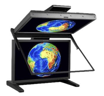
17 Volumetric displays with rotating screen The image is displayed in a certain volume, usually on a rotating surface. 17


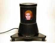
18 Examples of volumetric displays 18
19 Autostereoscopic displays Parallax barrier displays Parallax stereogram (panoramagram) Lenticular sheet displays Lenticular panoramagram Spherical integram Displays using time aperture Holographic stereograms 19

20 Use Parallax barrier displays a vertical mask in the shape of stripes placed at a specified distance in front of the display. Each eye of the observer sees different vertical stripes of the image on the display because each second stripe is shaded by mask stripes. 20


21 Parallax barrier displays... Dimesion Technologies As a parallax barrier, a separate translucent LCD panel can also be used to dynamically create vertical black bars so that the mask matches the current observer s position. In the DT technology bars are located beyond the LCD display media. The most important drawback is reduction of the brightness and resolution in half. 21


22 Lenticular sheet display Panel consisting of vertical stripes of cylindrical lenses lenticulars. Lenses play the same role as the parallax barrier, and as they are translucent, there is no loss of brightness. Are aligned with vertical pixel columns on the LCD panel located in the focal plane of the lenses. 22


23 Panoramagram and Integram Stereograms Lenticular panoramagram display 3D images only when viewers' eyes are in the horizontal direction (HPO). Panoramagram provides more than one angle of view. Integram provide a complete, 3D view independent of the point of view. Each type reduces the resolution multiple times. Integram 23


24 Displays using time aperture 1990s, the University of Cambridge presented a multiview autostereoscopic display based on high-speed CRT display and ferroelectric panel of liquid crystals. The CRT display showed images at high speed, each image for one view and one eye. 24
.")
, CRT is used instead of LCD.")
25 Multiplexed autostereoscopic The light strip passes through the lens and illuminates the image on the LCD. This image is only visible in the corresponding eyebox. (a). Cambridge display By successively lighting up the light strips, we get up to 8 views. In Cambridge Display (b), CRT is used instead of LCD. The Liquid crystal shutter is used to direct the light beam to the corresponding view 25


26 Multiplexed autostereoscopic High brightness and resolution are achieved by using three monochrome CRTs. Their images are merged into one beam, which is projected onto a spherical mirror. 26


27 Professional 3D displays These displays use the principle of stereoscopy with passive or active glasses or autostereoscopic technology. 27

28 Hologram Light from a laser is split into two beams. A beam that illuminates an object interferes with the reference beam and creates an interference pattern on the film. This pattern (hologram) contains information about the object, which is then used to reconstruct the 3D image of the object. 28


29 Hologram... Interference patterns look like water waves that are created when throwing stones into the lake. When displaying the 3D image stored in the hologram, we must place the laser into the same position as the reference beam. Then we will see the object image in the same place as the original object. It is as if the light from the object "froze" in the photographic plate and continued into the eye when reconstructing 3D image using 29 the laser beam.

30 Hologram... Image recostruction creates virtual 3D object. 30
 to draw individual points in a line. The horizontal \"scanning\" mirror deflects the beam to draw the individual lines of the picture.")
31 Electro-Holography A holographic image is created using acousto-optic modulator (AOM). The calculated interference pattern is sent to the AOM where it modulates the light wave. The beam uses a horizontal scanner (mirror) to draw individual points in a line. The horizontal "scanning" mirror deflects the beam to draw the individual lines of the picture. 31
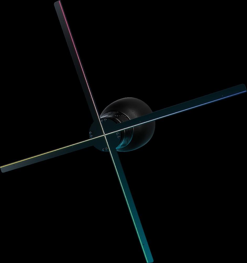
32 Pseudo 3D displays Many devices displaying the virtual image often have the name holographic : Hologram of Jessica Yellin, broadcast on CNN during US presidential elections in Image projected onto fog or an image that creates graphic patterns on drops of flowing water. Projected image on glass surface or semi-transparent film that uses the technique known as Pepper s ghost. Some of them have become an interesting commercial product: Kono-mo HypervsnTM uses fast-moving arms with miniature colour LEDs. 32


33 Examples of pseudo 3D displays 33
Mahdi Amiri. May Sharif University of Technology
 Course Presentation Multimedia Systems 3D Technologies Mahdi Amiri May 2014 Sharif University of Technology Binocular Vision (Two Eyes) Advantages A spare eye in case one is damaged. A wider field of view
Volumetric Hyper Reality: A Computer Graphics Holy Grail for the 21st Century? Gavin Miller Apple Computer, Inc.
 Volumetric Hyper Reality: A Computer Graphics Holy Grail for the 21st Century? Gavin Miller Apple Computer, Inc. Structure of this Talk What makes a good holy grail? Review of photo-realism Limitations
Realtime 3D Computer Graphics Virtual Reality
 Realtime 3D Computer Graphics Virtual Reality Human Visual Perception The human visual system 2 eyes Optic nerve: 1.5 million fibers per eye (each fiber is the axon from a neuron) 125 million rods (achromatic
An Introduction to 3D Computer Graphics, Stereoscopic Image, and Animation in OpenGL and C/C++ Fore June
 An Introduction to 3D Computer Graphics, Stereoscopic Image, and Animation in OpenGL and C/C++ Fore June Chapter 15 Stereoscopic Displays In chapters 8 through 10, we have discussed the principles and
Scaling of Rendered Stereoscopic Scenes
 University of West Bohemia in Pilsen Department of Computer Science and Engineering Univerzitni 8 30614 Pilsen Czech Republic Scaling of Rendered Stereoscopic Scenes Master Thesis Report Ricardo José Teixeira
CS 563 Advanced Topics in Computer Graphics Stereoscopy. by Sam Song
 CS 563 Advanced Topics in Computer Graphics Stereoscopy by Sam Song Stereoscopy Introduction Parallax Camera Displaying and Viewing Results Stereoscopy What is it? seeing in three dimensions creates the
Stereo. Shadows: Occlusions: 3D (Depth) from 2D. Depth Cues. Viewing Stereo Stereograms Autostereograms Depth from Stereo
 from 2D. Depth Cues. Viewing Stereo Stereograms Autostereograms Depth from Stereo") Stereo Viewing Stereo Stereograms Autostereograms Depth from Stereo 3D (Depth) from 2D 3D information is lost by projection. How do we recover 3D information? Image 3D Model Depth Cues Shadows: Occlusions:
Stereo Viewing Stereo Stereograms Autostereograms Depth from Stereo 3D (Depth) from 2D 3D information is lost by projection. How do we recover 3D information? Image 3D Model Depth Cues Shadows: Occlusions:
Prof. Feng Liu. Spring /27/2014
 Prof. Feng Liu Spring 2014 http://www.cs.pdx.edu/~fliu/courses/cs510/ 05/27/2014 Last Time Video Stabilization 2 Today Stereoscopic 3D Human depth perception 3D displays 3 Stereoscopic media Digital Visual
COMS W4172 Perception, Displays, and Devices 3
 COMS W4172 Perception, Displays, and Devices 3 Steven Feiner Department of Computer Science Columbia University New York, NY 10027 www.cs.columbia.edu/graphics/courses/csw4172 February 20, 2018 1 What
The topics are listed below not exactly in the same order as they were presented in class but all relevant topics are on the list!
 Ph332, Fall 2016 Study guide for the final exam, Part Two: (material lectured before the Nov. 3 midterm test, but not used in that test, and the material lectured after the Nov. 3 midterm test.) The final
3.3 Implementation of a Lenticular 3D Display
 56 Chapter 3 integral imaging can be understood as the number of different pixel data within a certain viewing angle. The angular resolution is determined by the number of pixels on the flat-panel display
Stereoscopic Systems Part 1
 Stereoscopic Systems Part 1 Terminology: Stereoscopic vs. 3D 3D Animation refers to computer animation created with programs (like Maya) that manipulate objects in a 3D space, though the rendered image
Conference Contribution to
 Conference Contribution to High resolution imaging for 3D multi-user displays by Dirk Müller, FG Digitaltechnik, IPM, FB 16, Universität Kassel Tel.: {+49 0} 561-804-6210 E-Mail: dirmuell@uni-kassel.de
Reprint. from the Journal. of the SID
 A 23-in. full-panel-resolution autostereoscopic LCD with a novel directional backlight system Akinori Hayashi (SID Member) Tomohiro Kometani Akira Sakai (SID Member) Hiroshi Ito Abstract An autostereoscopic
Animation Susen Rabold. Render. Engineers
 Animation 12-11-2009 Render 3D Engineers Susen Rabold Animation Computer animation started as early as the end of the 1950 s IBM and General Motors created Design augmented by Computers (DAC) Film animation
HoloGraphics. Combining Holograms with Interactive Computer Graphics
 HoloGraphics Combining Holograms with Interactive Computer Graphics Gordon Wetzstein Bauhaus University Weimar [gordon.wetzstein@medien.uni-weimar.de] 1 Location Weimar Dunedin Courtesy: NASA 2 HoloGraphics
Why should I follow this presentation? What is it good for?
 Why should I follow this presentation? What is it good for? Introduction into 3D imaging (stereoscopy, stereoscopic, stereo vision) S3D state of the art for PC and TV Compiling 2D to 3D Computing S3D animations,
Mobile 3D Display Technology to Realize Natural 3D Images
 3D Display 3D Image Mobile Device Special Articles on User Interface Research New Interface Design of Mobile Phones 1. Introduction Nowadays, as a new method of cinematic expression continuing from the
We are IntechOpen, the world s leading publisher of Open Access books Built by scientists, for scientists. International authors and editors
 We are IntechOpen, the world s leading publisher of Open Access books Built by scientists, for scientists 3,800 116,000 120M Open access books available International authors and editors Downloads Our
CSE 165: 3D User Interaction
 CSE 165: 3D User Interaction Lecture #4: Displays Instructor: Jurgen Schulze, Ph.D. CSE 165 - Winter 2015 2 Announcements Homework Assignment #1 Due tomorrow at 1pm To be presented in CSE lab 220 Homework
Holojackets. Semester Update: Fall 2017 December 4, 2017
 Holojackets Semester Update: Fall 2017 December 4, 2017 Agenda Team Focus Problem Statement Background Research Team Structure Progress Conclusion/Project Plan 2 Team Focus Prototype 3D displays that allow
CSE 165: 3D User Interaction. Lecture #3: Displays
 CSE 165: 3D User Interaction Lecture #3: Displays CSE 165 -Winter 2016 2 Announcements Homework Assignment #1 Due Friday at 2:00pm To be presented in CSE lab 220 Paper presentations Title/date due by entering
Friday, 22 August 14. Lenticular prints
 Lenticular prints Motivation Giving researchers the ability to present work in 3D in print and without glasses (autostereoscopic). Avoiding the need to take display hardware to conferences for poster sessions.
Chapter 38. Diffraction Patterns and Polarization
 Chapter 38 Diffraction Patterns and Polarization Diffraction Light of wavelength comparable to or larger than the width of a slit spreads out in all forward directions upon passing through the slit This
Holographic stereograms as discrete imaging systems Michael W. Halle MIT Media Laboratory 20 Ames St. Cambridge, MA USA ABSTRACT
 To appear in SPIE Proceeding #2176 Practical Holography VIII (SPIE, Bellingham, WA, February 1994) paper #10 (in press). Holographic stereograms as discrete imaging systems Michael W. Halle MIT Media Laboratory
Dynamic Light Sculpting: Creating True 3D Holograms With GPUs
 Dynamic Light Sculpting: Creating True 3D Holograms With GPUs TM Official partner Key innovator in a volumetric sector worth 2bn according to MPEG committee on Immersive Media contributor From Augmented
Digital holographic display with two-dimensional and threedimensional convertible feature by high speed switchable diffuser
 https://doi.org/10.2352/issn.2470-1173.2017.5.sd&a-366 2017, Society for Imaging Science and Technology Digital holographic display with two-dimensional and threedimensional convertible feature by high
10.5 Polarization of Light
 10.5 Polarization of Light Electromagnetic waves have electric and magnetic fields that are perpendicular to each other and to the direction of propagation. These fields can take many different directions
Department of Photonics, NCTU, Hsinchu 300, Taiwan. Applied Electromagnetic Res. Inst., NICT, Koganei, Tokyo, Japan
 A Calibrating Method for Projected-Type Auto-Stereoscopic 3D Display System with DDHOE Ping-Yen Chou 1, Ryutaro Oi 2, Koki Wakunami 2, Kenji Yamamoto 2, Yasuyuki Ichihashi 2, Makoto Okui 2, Jackin Boaz
CHAPTER 2: THREE DIMENSIONAL TOPOGRAPHICAL MAPPING SYSTEM. Target Object
 CHAPTER 2: THREE DIMENSIONAL TOPOGRAPHICAL MAPPING SYSTEM 2.1 Theory and Construction Target Object Laser Projector CCD Camera Host Computer / Image Processor Figure 2.1 Block Diagram of 3D Areal Mapper
RV - AULA 07 - PSI3502/2018. Displays
 RV - AULA 07 - PSI3502/2018 Displays Outline Discuss various types of output devices, also known as displays. Examine the video displays as one of the most widely used and most diverse group of displays.
specular diffuse reflection.
 Lesson 8 Light and Optics The Nature of Light Properties of Light: Reflection Refraction Interference Diffraction Polarization Dispersion and Prisms Total Internal Reflection Huygens s Principle The Nature
Head Mounted Display for Mixed Reality using Holographic Optical Elements
 Mem. Fac. Eng., Osaka City Univ., Vol. 40, pp. 1-6 (1999) Head Mounted Display for Mixed Reality using Holographic Optical Elements Takahisa ANDO*, Toshiaki MATSUMOTO**, Hideya Takahashi*** and Eiji SHIMIZU****
Basic distinctions. Definitions. Epstein (1965) familiar size experiment. Distance, depth, and 3D shape cues. Distance, depth, and 3D shape cues
 familiar size experiment. Distance, depth, and 3D shape cues. Distance, depth, and 3D shape cues") Distance, depth, and 3D shape cues Pictorial depth cues: familiar size, relative size, brightness, occlusion, shading and shadows, aerial/ atmospheric perspective, linear perspective, height within image,
Distance, depth, and 3D shape cues Pictorial depth cues: familiar size, relative size, brightness, occlusion, shading and shadows, aerial/ atmospheric perspective, linear perspective, height within image,
V530-R150E-3, EP-3. Intelligent Light Source and a Twocamera. Respond to a Wide Variety of Applications. 2-Dimensional Code Reader (Fixed Type)
") 2-Dimensional Code Reader (Fixed Type) Intelligent Light Source and a Twocamera Unit Respond to a Wide Variety of Applications Features Intelligent Light Source Versatile lighting control and a dome shape
2-Dimensional Code Reader (Fixed Type) Intelligent Light Source and a Twocamera Unit Respond to a Wide Variety of Applications Features Intelligent Light Source Versatile lighting control and a dome shape
Technologies of Digital Holographic Display
 Technologies of Digital Holographic Display Joonku Hahn Kyungpook National University Outline: 1. Classification of digital holographic display 2. Data capacity, View volume and Resolution 3. Holographic
Simplicity vs. Flexibility
 Simplicity vs. Flexibility An integrated system approach to stereography 1 The old Business Of 3D Technology 2 The old Business Of 3D 20s 50s 90s 3 So is this time different? 4 Teleoperation Travel $2.7
Diffraction. Single-slit diffraction. Diffraction by a circular aperture. Chapter 38. In the forward direction, the intensity is maximal.
 Diffraction Chapter 38 Huygens construction may be used to find the wave observed on the downstream side of an aperture of any shape. Diffraction The interference pattern encodes the shape as a Fourier
Unit 9 Light & Optics
 Unit 9 Light & Optics 1 A quick review of the properties of light. Light is a form of electromagnetic radiation Light travels as transverse waves having wavelength and frequency. fλ=c The velocity of EMR
Office Hours. Scattering and Polarization
 Office Hours Office hours are posted on the website. Molly: Tuesdays 2-4pm Dr. Keister: Wednesdays 10am-12 Prof. Goldman: Wednesdays 2-3:30pm All office hours are in the help room downstairs If none of
Chapter 2: Wave Optics
 Chapter : Wave Optics P-1. We can write a plane wave with the z axis taken in the direction of the wave vector k as u(,) r t Acos tkzarg( A) As c /, T 1/ and k / we can rewrite the plane wave as t z u(,)
Light and refractive index
 17 Fig. 7.1 shows a ray of light incident on a rectangular glass block at point X. W P X air glass Q R S Fig. 7.1 The ray of light is refracted at X. On Fig. 7.1, (a) draw the normal at X, [1] (b) draw
LIGHT Measuring Angles
 1. Using a protractor LIGHT Measuring Angles This angle is 33 Put vertex (corner) of angle where lines cross One arm of angle goes through middle of 0 This angle is 45 Measure these angles: 66 Light an
4. A bulb has a luminous flux of 2400 lm. What is the luminous intensity of the bulb?
 1. Match the physical quantities (first column) with the units (second column). 4. A bulb has a luminous flux of 2400 lm. What is the luminous intensity of the bulb? (π=3.) Luminous flux A. candela Radiant
Principle of LCD Display Section D
 Principle of LCD Display Section D 2 Contents 1. What s Liquid Crystals (LC) 2. Introduction to Liquid Crystal Displays 3. Operating Principle 4. Applications A) Thin Film Transistor (TFT) B) Alpha-numeric
Downloaded from UNIT 06 Optics
 1 Mark UNIT 06 Optics Q1: A partially plane polarised beam of light is passed through a polaroid. Show graphically the variation of the transmitted light intensity with angle of rotation of the Polaroid.
Shading of a computer-generated hologram by zone plate modulation
 Shading of a computer-generated hologram by zone plate modulation Takayuki Kurihara * and Yasuhiro Takaki Institute of Engineering, Tokyo University of Agriculture and Technology, 2-24-16 Naka-cho, Koganei,Tokyo
Full Color Image Splitter Based on Holographic Optical Elements for Stereogram Application
 JOURNAL OF DISPLAY TECHNOLOGY, VOL. 9, NO. 8, AUGUST 2013 607 Full Color Image Splitter Based on Holographic Optical Elements for Stereogram Application Qing-Long Deng, Wei-Chia Su, Chien-Yue Chen, Bor-Shyh
OPTICS MIRRORS AND LENSES
 Downloaded from OPTICS MIRRORS AND LENSES 1. An object AB is kept in front of a concave mirror as shown in the figure. (i)complete the ray diagram showing the image formation of the object. (ii) How will
Stereoscopic Presentations Taking the Difficulty out of 3D
 Stereoscopic Presentations Taking the Difficulty out of 3D Andrew Woods, Centre for Marine Science & Technology, Curtin University, GPO Box U1987, Perth 6845, AUSTRALIA Email: A.Woods@cmst.curtin.edu.au
Three dimensional Binocular Holographic Display Using Liquid Crystal Shutter
 Journal of the Optical Society of Korea Vol. 15, No. 4, December 211, pp. 345-351 DOI: http://dx.doi.org/1.387/josk.211.15.4.345 Three dimensional Binocular Holographic Display Using iquid Crystal Shutter
Lecture Outline Chapter 26. Physics, 4 th Edition James S. Walker. Copyright 2010 Pearson Education, Inc.
 Lecture Outline Chapter 26 Physics, 4 th Edition James S. Walker Chapter 26 Geometrical Optics Units of Chapter 26 The Reflection of Light Forming Images with a Plane Mirror Spherical Mirrors Ray Tracing
Refraction and Polarization of Light
 Chapter 9 Refraction and Polarization of Light Name: Lab Partner: Section: 9.1 Purpose The purpose of this experiment is to demonstrate several consequences of the fact that materials have di erent indexes
UNIT 102-9: INTERFERENCE AND DIFFRACTION
 Name St.No. - Date(YY/MM/DD) / / Section Group # UNIT 102-9: INTERFERENCE AND DIFFRACTION Patterns created by interference of light in a thin film. OBJECTIVES 1. Understand the creation of double-slit
2.) An overhead projector forms an image of a transparency on a screen:
 An overhead projector forms an image of a transparency on a screen:") 1.) You have measured the wavelength λ of a spectral lamp using a diffraction grating and the relation λ = d sin Θ. Your uncertainty in the grating spacing d is 0.5% and your uncertainty in your angle
1.) You have measured the wavelength λ of a spectral lamp using a diffraction grating and the relation λ = d sin Θ. Your uncertainty in the grating spacing d is 0.5% and your uncertainty in your angle
Distortion Correction for Conical Multiplex Holography Using Direct Object-Image Relationship
 Proc. Natl. Sci. Counc. ROC(A) Vol. 25, No. 5, 2001. pp. 300-308 Distortion Correction for Conical Multiplex Holography Using Direct Object-Image Relationship YIH-SHYANG CHENG, RAY-CHENG CHANG, AND SHIH-YU
Video Communication Ecosystems. Research Challenges for Immersive. over Future Internet. Converged Networks & Services (CONES) Research Group
 Research Group") Research Challenges for Immersive Video Communication Ecosystems over Future Internet Tasos Dagiuklas, Ph.D., SMIEEE Assistant Professor Converged Networks & Services (CONES) Research Group Hellenic Open
Research Challenges for Immersive Video Communication Ecosystems over Future Internet Tasos Dagiuklas, Ph.D., SMIEEE Assistant Professor Converged Networks & Services (CONES) Research Group Hellenic Open
Person s Optics Test SSSS
 Person s Optics Test SSSS 2017-18 Competitors Names: School Name: All questions are worth one point unless otherwise stated. Show ALL WORK or you may not receive credit. Include correct units whenever
The Graphics Pipeline and OpenGL IV: Stereo Rendering, Depth of Field Rendering, Multi-pass Rendering!
 ! The Graphics Pipeline and OpenGL IV: Stereo Rendering, Depth of Field Rendering, Multi-pass Rendering! Gordon Wetzstein! Stanford University! EE 267 Virtual Reality! Lecture 6! stanford.edu/class/ee267/!!
Natural Viewing 3D Display
 We will introduce a new category of Collaboration Projects, which will highlight DoCoMo s joint research activities with universities and other companies. DoCoMo carries out R&D to build up mobile communication,
CHAPTER 2 AUTOSTEREOSCOPIC DISPLAY TYPES AND HUMAN FACTORS
 CHAPTER 2 AUTOSTEREOSCOPIC DISPLAY TYPES AND HUMAN FACTORS 2.1) Preface In the first part of this chapter, the implementation and the various advantages and disadvantages of non-head tracking autostereoscopic
ENGR142 PHYS 115 Geometrical Optics and Lenses
 ENGR142 PHYS 115 Geometrical Optics and Lenses Part A: Rays of Light Part B: Lenses: Objects, Images, Aberration References Pre-lab reading Serway and Jewett, Chapters 35 and 36. Introduction Optics play
PHYS2002 Spring 2012 Practice Exam 3 (Chs. 25, 26, 27) Constants
 Constants") PHYS00 Spring 01 Practice Exam 3 (Chs. 5, 6, 7) Constants m m q q p e ε = 8.85 o o p e = 1.67 = 9.11 7 9 7 31 = + 1.60 = 1.60 μ = 4π k = 8.99 g = 9.8 m/s 1 kg 19 19 C kg T m/a N m C / N m C / C 1. A convex
PHYS00 Spring 01 Practice Exam 3 (Chs. 5, 6, 7) Constants m m q q p e ε = 8.85 o o p e = 1.67 = 9.11 7 9 7 31 = + 1.60 = 1.60 μ = 4π k = 8.99 g = 9.8 m/s 1 kg 19 19 C kg T m/a N m C / N m C / C 1. A convex
Design and production of stereoscopic instruments. User manual for the 3-D macro lens model General. Exposure
 Ing. J. de Wijs. Populierstraat 44, 4131 AR Vianen, the Netherlands Tel/Fax. +31 (0)347-372242 e-mail: info@dewijs-3d.com Website: www.dewijs-3d.com Design and production of stereoscopic instruments. Bank:
Stereo plotting over orientated photographs
 TcpStereo for drones Stereo plotting over orientated photographs Introduction This system allows stereo plotting in CAD platform over aerial photographs with previously defined orientations. It works from
Non-Contact Depth Measuring Microscope System DH2/IMH
 Non-Contact Depth Measuring Microscope System DH2/IMH Specially designed focus indicator (Target Mark) facilitates focusing operation greatly. Highly accurate and repeatable measurement is possible. No
Design and visualization of synthetic holograms for security applications
 Journal of Physics: Conference Series Design and visualization of synthetic holograms for security applications To cite this article: M Škere et al 2013 J. Phys.: Conf. Ser. 415 012060 Related content
Light: Geometric Optics
 Light: Geometric Optics The Ray Model of Light Light very often travels in straight lines. We represent light using rays, which are straight lines emanating from an object. This is an idealization, but
Mu lt i s p e c t r a l
 Viewing Angle Analyser Revolutionary system for full spectral and polarization measurement in the entire viewing angle EZContrastMS80 & EZContrastMS88 ADVANCED LIGHT ANALYSIS by Field iris Fourier plane
Directional Backlights for Time-multiplexed 3D Displays. As the advancement of image display from monochromic to color, each
 Chapter 6 Directional Backlights for Time-multiplexed 3D Displays As the advancement of image display from monochromic to color, each development is driven by pursuing ever more natural visions. Therefore,
Conceptual Physics 11 th Edition
 Conceptual Physics 11 th Edition Chapter 28: REFLECTION & REFRACTION This lecture will help you understand: Reflection Principle of Least Time Law of Reflection Refraction Cause of Refraction Dispersion
Lesson Plan Outline for Rainbow Science
 Lesson Plan Outline for Rainbow Science Lesson Title: Rainbow Science Target Grades: Middle and High School Time Required: 120 minutes Background Information for Teachers and Students Rainbows are fascinating
3D Photography: A Personal Experience of Analogue and Digital Cameras
 3D Photography: A Personal Experience of Analogue and Digital Cameras William Carey (HSF-ISR) ESTEC February 2011 Slide 1 The Beginning Cervantes Mission (2003) Pedro Duque Erasmus Centre (ESTEC) Current:
Multi-View Omni-Directional Imaging
 Multi-View Omni-Directional Imaging Tuesday, December 19, 2000 Moshe Ben-Ezra, Shmuel Peleg Abstract This paper describes a novel camera design or the creation o multiple panoramic images, such that each
LENS INSTALLATION GUIDE
 Paladin Lens Phoenix Lens LENS INSTALLATION GUIDE The Paladin and Phoenix lens systems represent the latest generation in patented anamorphic optical solutions to engage the anamorphic modes available
Overview of Active Vision Techniques
 SIGGRAPH 99 Course on 3D Photography Overview of Active Vision Techniques Brian Curless University of Washington Overview Introduction Active vision techniques Imaging radar Triangulation Moire Active
BCC Sphere Transition
 BCC Sphere Transition The Sphere Transition shape models the source image onto a sphere. Unlike the Sphere filter, the Sphere Transition filter allows you to animate Perspective, which is useful in creating
Fresnel's biprism and mirrors
 Fresnel's biprism and mirrors 1 Table of Contents Section Page Back ground... 3 Basic Experiments Experiment 1: Fresnel's mirrors... 4 Experiment 2: Fresnel's biprism... 7 2 Back ground Interference of
Computer Graphics. Chapter 1 (Related to Introduction to Computer Graphics Using Java 2D and 3D)
") Computer Graphics Chapter 1 (Related to Introduction to Computer Graphics Using Java 2D and 3D) Introduction Applications of Computer Graphics: 1) Display of Information 2) Design 3) Simulation 4) User
Computer Graphics Chapter 1 (Related to Introduction to Computer Graphics Using Java 2D and 3D) Introduction Applications of Computer Graphics: 1) Display of Information 2) Design 3) Simulation 4) User
TFT-LCD Technology Introduction
 TFT-LCD Technology Introduction Thin film transistor liquid crystal display (TFT-LCD) is a flat panel display one of the most important fields, because of its many advantages, is the only display technology
IB-2 Polarization Practice
 Name: 1. Plane-polarized light is incident normally on a polarizer which is able to rotate in the plane perpendicular to the light as shown below. In diagram 1, the intensity of the incident light is 8
SXGA-R2-H1 FLCOS Microdisplay & Interface Electronics
 SXGA-R2-H1 FLCOS Microdisplay & Interface Electronics Features Reflective microdisplay - 0.88 /22.4mm diagonal High resolution - SXGA (1280 x 1024 pixels) Ferroelectric Liquid Crystal on Silicon (FLCOS)
UNIT VI OPTICS ALL THE POSSIBLE FORMULAE
 58 UNIT VI OPTICS ALL THE POSSIBLE FORMULAE Relation between focal length and radius of curvature of a mirror/lens, f = R/2 Mirror formula: Magnification produced by a mirror: m = - = - Snell s law: 1
3D Display and AR. Linda Li, Rokid Rlab Dec. 27, 2016
 3D Display and AR Linda Li, Rokid Rlab Dec. 27, 2016 1 Five OLED Trends of Future Tactile / Haptic Touch Displays Higher Pixel Density Glasses-free 3D Virtue Reality and Augmented Reality 1 Stereoscopic
Lighting & 3D Graphics. Images from 3D Creative Magazine
 Lighting & 3D Graphics Images from 3D Creative Magazine Contents Introduction Definitions 3D Lighting Basics 3D Light Sources Lighting Controls & Effects Brightness & Colour Shadows Hotspot And Falloff
Chapter 26 Geometrical Optics
 Chapter 26 Geometrical Optics 26.1 The Reflection of Light 26.2 Forming Images With a Plane Mirror 26.3 Spherical Mirrors 26.4 Ray Tracing and the Mirror Equation 26.5 The Refraction of Light 26.6 Ray
Chapter 24. Wave Optics
 Chapter 24 Wave Optics Wave Optics The wave nature of light is needed to explain various phenomena Interference Diffraction Polarization The particle nature of light was the basis for ray (geometric) optics
Enhanced Still 3D Integral Images Rendering Based on Multiprocessor Ray Tracing System
 Journal of Image and Graphics, Volume 2, No.2, December 2014 Enhanced Still 3D Integral Images Rendering Based on Multiprocessor Ray Tracing System M. G. Eljdid Computer Sciences Department, Faculty of
AUTOSTEREOSCOPIC, PARTIAL PIXEL, SPATIALLY MULTIPLEXED, AND OTHER 3D DISPLAY TECHNOLOGIES
 Chapter 13 AUTOSTEREOSCOPIC, PARTIAL PIXEL, SPATIALLY MULTIPLEXED, AND OTHER 3D DISPLAY TECHNOLOGIES Monish R. Chatterjee^ and Shih-Tun Chen^ ^University of Dayton, Dayton, OH 45469; ^Teradyne Inc., Agoura
FSST Passive 3D Kit for Blackwing (3D models) ASSEMBLY AND CALIBRATION. Part. No.: R Ref: R Rev: 01
 ASSEMBLY AND CALIBRATION. Part. No.: R Ref: R Rev: 01") FSST Passive 3D Kit for Blackwing (3D models) ASSEMBLY AND CALIBRATION www.cineversum.com Ref: R1048214-222 Rev: 01 Part. No.: R599825 Changes Cineversum provides this manual as is without warranty of
FSST Passive 3D Kit for Blackwing (3D models) ASSEMBLY AND CALIBRATION www.cineversum.com Ref: R1048214-222 Rev: 01 Part. No.: R599825 Changes Cineversum provides this manual as is without warranty of
1.! Questions about reflected intensity. [Use the formulas on p. 8 of Light.] , no matter
![1.! Questions about reflected intensity. [Use the formulas on p. 8 of Light.] , no matter](/thumbs/81/83191942.jpg "1.! Questions about reflected intensity. [Use the formulas on p. 8 of Light.] , no matter") Reading: Light Key concepts: Huygens s principle; reflection; refraction; reflectivity; total reflection; Brewster angle; polarization by absorption, reflection and Rayleigh scattering. 1.! Questions about
Reading: Light Key concepts: Huygens s principle; reflection; refraction; reflectivity; total reflection; Brewster angle; polarization by absorption, reflection and Rayleigh scattering. 1.! Questions about
Refraction and Polarization of Light
 Chapter 9 Refraction and Polarization of Light Name: Lab Partner: Section: 9.1 Purpose The purpose of this experiment is to demonstrate several consequences of the fact that materials have di erent indexes
25 The vibration spiral
 25 The vibration spiral Contents 25.1 The vibration spiral 25.1.1 Zone Plates............................... 10 25.1.2 Circular obstacle and Poisson spot.................. 13 Keywords: Fresnel Diffraction,
A novel 3D display based on micro-volumetric scanning and real time reconstruction of holograms principle Guangjun Wang a,b
 A novel 3D display based on micro-volumetric scanning and real time reconstruction of holograms principle Guangjun Wang a,b a BOWEI INTEGRATED CIRCUITS CO.,LTD., The 13th Research Institute of China Electronics
Multimedia Technology CHAPTER 4. Video and Animation
 CHAPTER 4 Video and Animation - Both video and animation give us a sense of motion. They exploit some properties of human eye s ability of viewing pictures. - Motion video is the element of multimedia
AP* Optics Free Response Questions
 AP* Optics Free Response Questions 1978 Q5 MIRRORS An object 6 centimeters high is placed 30 centimeters from a concave mirror of focal length 10 centimeters as shown above. (a) On the diagram above, locate
CSE 167: Lecture #7: Color and Shading. Jürgen P. Schulze, Ph.D. University of California, San Diego Fall Quarter 2011
 CSE 167: Introduction to Computer Graphics Lecture #7: Color and Shading Jürgen P. Schulze, Ph.D. University of California, San Diego Fall Quarter 2011 Announcements Homework project #3 due this Friday,
Chapter 26 Geometrical Optics
 Chapter 26 Geometrical Optics 1 Overview of Chapter 26 The Reflection of Light Forming Images with a Plane Mirror Spherical Mirrors Ray Tracing and the Mirror Equation The Refraction of Light Ray Tracing
Challenge of 3D LCD Displays
 Invited Paper Challenge of 3D LCD Displays Rung-Ywan Tsai, Chao-Hsu Tsai, Kuen Lee, Chou-Lin Wu, Lang-Chin D. Lin, Kuo-Chung Huang, Wei-Liang Hsu, Chang-Shuo Wu, Chun-Fu Lu, Jinn-Cherng Yang, Ying-Chi
A Fast Image Multiplexing Method Robust to Viewer s Position and Lens Misalignment in Lenticular 3D Displays
 A Fast Image Multiplexing Method Robust to Viewer s Position and Lens Misalignment in Lenticular D Displays Yun-Gu Lee and Jong Beom Ra Department of Electrical Engineering and Computer Science Korea Advanced