Finite Element Method. Chapter 7. Practical considerations in FEM modeling
|
|
|
- Jeffrey Sutton
- 5 years ago
- Views:
Transcription
1 Finite Element Method Chapter 7 Practical considerations in FEM modeling
2 Finite Element Modeling General Consideration The following are some of the difficult tasks (or decisions) that face the engineer when modeling: 1-Understanding the physical behavior of both the problem and the various elements available for use. 2- Choosing the proper type of element (or elements) to match as closely as possible the physical behavior of the problem. 3- Understanding the boundary conditions imposed on the problem. Determining the kinds, magnitudes, and locations of the loads that must be applied to the body. Good modeling techniques are acquired through experience, working with experienced people, searching the literature, and using general-purpose programs
3 Aspect Ratio and Element shapes Aspect Ratio = Longest Dimension/ Shortest Dimension Figure 7-1a Beam with loading: effects of the Aspect Ratio (AR) illustrated by the five cases with different aspect ratios
4 Inaccuracy of solution as a function of the aspect ratio Displacement at Point A
5 Comparison of results for various aspect ratios
6 Elements with Poor Shapes
7
8 Avoid Abrupt Changes in Element Sizes Abrupt change in element size Gradual change in element size
9 Examples of how NOT to connect elements
10 Use of Symmetry in Modeling Use of symmetry applied to a uniaxially loaded member with a fillet
11 Use of Symmetry in Modeling Figure 7-5 Problem reduction using axes of symmetry applied to a plate with a hole subjected to tensile force
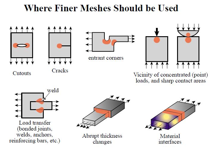
12 Natural subdivisions at discontinuities
13
14
15 Natural subdivisions at discontinuities
16 Connecting (Mixing) Different Kinds of Elements Connecting beam element to plane elements (a) No moment is transferred, (b) moment is transferred
17 Infinite Medium The soil mass subjected to a foundation load is a typical model that represents an infinite medium. The main guideline here is that enough material must be included such that the displacements at nodes and stresses within the elements become negligibly small at locations far from the foundation load. Experience of some investigators has shown that, for homogeneous soil mass, influence of footing becomes insignificant if: The horizontal distance of the model is taken as approximately 4 to 6 times the width of the footing, and The vertical distance is taken approximately 4 to ten times the width of the footing.
18 Infinite Medium Figure 7-3 Use of symmetry applied to a soil mass subjected to foundation loading (number of nodes = 66, number of element= 50)
19 Mesh Refinement h-refinement p-refinement h=element size p=polynomial order The discretization depends on the geometry of the structure, the loading pattern, and the boundary conditions. For instance, regions of stress concentration or high stress gradient due to fillets, holes, or re-entrant corners require a finer mesh near those regions
20 Example of h and p refinement
21 R-Mesh Refinement r-refinement In the r method of refinement, the nodes are rearranged or relocated without changing the number of elements or the polynomial degree of their field quantities.
22 Transition Triangles
23 Transition Elements using triangular transition elements using quadrilateral transition elements Refinement by h-method
24 Transition Triangles Hanging node (irregular node) Using Elements with Hanging nodes using different numbers of nodes at each side. Refinement by h-method
 4(-1,1) 7(0,1) 3(1,1) 7( 3,1) 4(-1,1) 3(1,1) 8(-1,0) 6(1,0) 9(0,0) 9(, ) 1(-1,-1) 5(0,-1) 2(1,-1) 1(-1,-1) 2(1,-1) 5( 1,-1) Standard Element")
25 Modified isoparametric elements (Arafa, 2005) If 1 4 0, 0 and 0 The shape functions will be the standard Lagrange shape functions. 6(1, 2 ) 4(-1,1) 7(0,1) 3(1,1) 7( 3,1) 4(-1,1) 3(1,1) 8(-1,0) 6(1,0) 9(0,0) 9(, ) 1(-1,-1) 5(0,-1) 2(1,-1) 1(-1,-1) 2(1,-1) 5( 1,-1) Standard Element 8(-1, 4 ) Modified Element
26 Applications of the modified elements in mesh refinement
27 Look before you leap! 1. Check the model that you have developed: Boundary conditions Loadings Symmetry? Element aspect ratios/shapes Mesh gradation 2. Check the results Eyeball Anything funny (nonzero displacements where they should be zero?) Are stress concentrations in places that you expect? Comparison with known analytical solution/literature 3. If you remesh the same problem and analyze, do the solutions converge?
28 Equilibrium and Compatibility of Finite Element Results An approximate FE solution for a stress analysis problem, based on assumed displacement fields, does not generally satisfy all the requirements for equilibrium and compatibility that an exact theory-of-elasticity solution satisfies. However, remember that relatively few exact solutions exist. Hence, the finite element method is a very practical one obtaining reasonable, but approximate, numerical solutions. We now describe some of the approximations generally inherent in finite element solutions
29 Equilibrium and Compatibility of Finite Element Results 1- Equilibrium of nodal forces and moments is satisfied: This is true because the global equation F = K d is a nodal equilibrium equation whose solution for d is such that the sums of all forces and moments applied to each node are zero. Equilibrium of the whole structure also satisfied because the structure reactions are included in the global forces, and hence, in the nodal equilibrium equations.
30 Equilibrium and Compatibility of Finite Element Results 2- Equilibrium within an element is not always satisfied: For the constant-strain bar of Chapter 3 and the constant-strain triangle of Chapter 6, element equilibrium is satisfied. The cubic displacement function is shown to satisfy the basic beam equilibrium differential equation in Chapter 5, and hence, to satisfy element force and moment equilibrium. However, elements such as the linear-strain triangle of Chapter 8 the axisymmetric element of Chapter 9, and the rectangular element of Chapter 10 usually only approximately satisfy the element equilibrium equations.
31 Equilibrium and Compatibility of Finite Element Results 3- Equilibrium is not usually satisfied between elements: A differential element including parts of two adjacent finite elements is usually not in equilibrium. For line elements, such as used for truss and frame analysis, interelement equilibrium is satisfied as shown in examples in Chapters 3 through 6. However, for two- and three-dimensional elements, interelement equilibrium is not usually satisfied.
32 Equilibrium and Compatibility of Finite Element Results 4- Compatibility is satisfied within an element Hence, individual elements do not tear apart. 5-Compatibility is satisfied at the nodes Hence, elements remain connected at their common nodes. Similarly, the structure remains connected to its support nodes because boundary conditions are invoked at these nodes.
33 Equilibrium and Compatibility of Finite Element Results 6-Compatibility may or may not be satisfied along interelement boundaries. For line elements such as bars and beams, interelement boundaries are merely nodes. Therefore, the preceding statement 5 applies for these line elements. The constant-strain triangle of Chapter 6 and the rectangular element of Chapter 10 remain straight sided when deformed and therefore, interelement compatibility exists for these elements; that is, these plane elements deform along common lines without openings, overlaps, or discontinuities. Incompatible elements, those that allow gaps or overlaps between elements, can be acceptable and even desirable. Incompatible element formulations, in some cases, have been shown to converge more rapidly to the exact solution.
34 Convergence of solution In previous sections, we presented guidelines for the selection of so-called compatible and complete displacement functions. Those guidelines are generally applicable, and their satisfaction ensures monotonic convergence of the solution.
35 Interpretation of Stresses For elements using linear-displacement models, such as the bar and the constant-strain triangle, [B] is constant, and since we assume [D] to be constant, the stresses are constant over the element. In this case, it is common practice to assign the stress to the centroid of the element with acceptable results.
36 Interpretation of Stresses The figure shown compares the exact beam theory solution for bending stress through the beam depth at the centroid of the elements next to the wall with the finite element solution. For higher-order elements, such as the linear-strain triangle of Chapter 8. [B] and hence the stresses, are functions of the coordinates. The common practice is then to directly evaluate the stresses at the centroid of the element.
37 The following two properties are ALWAYS satisfied by the FEM solution using a coarse or a fine mesh Property 1: Nodal point equilibrium Property 2. Element equilibrium P El #4 El #3 El #2 El #1 PROPERTY 1: (Nodal point equilibrium) At any node the sum of the element nodal point forces is in equilibrium with the externally applied loads (including all effects due to body forces, surface tractions, initial stresses, concentrated loads, inertia, damping and reaction)
38 Nodal point equilibrium implies: This is equal in magnitude and in the same direction as P P El #4 El #3 El #2 El #1 Sum of forces equal externally applied load (=0 at this node)
39 F 4x F 1x PROPERTY 2: (Element equilibrium) Each element is in equilibrium under its forces f i.e., each element is under force and moment equilibrium e.g., F 4y F 1y Hence F 3y F 2y F 3x F 2x F F F F 1x 2x 3x 4x 0 Define T e d as a rigid body displacement in x-direction T T T d f d B dv T d f F F F F But V 1x 2x 3x 4x T V 0 Bd 0 e T d B dv Since this is a rigid body displacement, the strains are zero
40 Example (Finite Element Procedures, Bathe 1996)
41 Example (Finite Element Procedures, Bathe 1996)
42 Example (Finite Element Procedures, Bathe 1996)
43 Example (Finite Element Procedures, Bathe 1996)
44 Example (Finite Element Procedures, Bathe 1996)
45 Example (Finite Element Procedures, Bathe 1996)
46
47 In a Finite Element Analysis 1. Stress equilibrium violated inside each element 2. Stresses are discontinuous across elements 3. Stresses are not in equilibrium with the applied traction 4. Compatibility and stress-strain relationships are exactly satisfied. 5. Instead of force equilibrium at the differential level, only global equilibrium for the complete structure is satisfied. 6. The equilibrium of nodal points of each element under its nodal point forces is satisfied.
48 Patch Test To guarantee the convergence of a solution, the element being used in your model must pass a test called the patch test The patch test is based on that the element must be able to accommodate both rigid-body motion and constant states of strain as both are possible within a structure. The patch test then can be used to determine if an element satisfies convergence requirements. It also can be applied to determine if sufficient Gauss points have been used in the numerical integration process to evaluate the stiffness matrix when the concept of isoparametric formulation of stiffness matrices is used as described in Chapter 10.
49 Patch Test The patch test is performed by considering a simple finite element model composed of four irregular shaped elements of the same material with at least one node inside of the patch (called the patch node), The elements should be irregular, as some regular elements (such as rectangular) may pass the test whereas irregular ones will not. The elements may be all triangles or quadrilaterals or a mix of both. The boundary can be a rectangle though
50 Patch Test Step 1 Assume a uniform stress state of x =1 or some convenient constant value is applied along the right side of the patch. Replace this stress with its work-equivalent nodal load. Step 2 Internal node 5 is not loaded. Step 3 The patch has just enough supports to prevent rigidbody motion. Step 4 The finite element direct stiffness method is again used to obtain the displacements and element stresses. The uniform stress sx ¼ 1 should be
51 The displacement Patch Test The displacement patch test can be used to check if the elements can represent rigid-body motion and a constant state of strain. To verify if the elements can represent rigid-body motion, we do the following:

52 The displacement Patch Test To verify if the elements can represent rigid-body motion, we do the following:

53 The displacement Patch Test To verify if the elements can represent a state of constant strain, the following steps are taken:
54 The Force Patch Test The force patch test validates that errors associated with the applied loads do not occur. The steps are as follows:: Step 1 Assume a uniform stress state of x =1 or some convenient constant value is applied along the right side of the patch. Replace this stress with its work-equivalent nodal load. Step 2 Internal node 5 is not loaded. Step 3 The patch has just enough supports to prevent rigidbody motion.
55 The Force Patch Test The force patch test validates that errors associated with the applied loads do not occur. The steps are as follows:: Step 4 The finite element direct stiffness method is again used to obtain the displacements and element stresses. The uniform stress x =1 should be obtained within each element. The other in-plane stresses, y and xy should be zero. Step 5 Repeat the steps assuming first that y =1 and the other stresses are zero. Then assume that xy and the two normal stresses equal zero
56 The Patch Test An element that passes the patch test is capable of meeting the following requirements: a) Predicting rigid-body motion without strain when this state exists. b) Predicting states of constant strain if they occur. c) Compatibility with adjacent elements when a state of constant strain exists in adjacent elements. When these requirements are met, it is sufficient to guarantee that a mesh of these elements will yield convergence to the solution as the mesh is continually refined. The patch test is a standard test for developers of new elements. Whether the element has the necessary convergence properties. But the test does not indicate how well an element works in other applications. An element passing the patch test may still yield poor accuracy in a coarse mesh or show slow convergence as the mesh is refined.
57 HW: (One problem for each student)
Chapter 7 Practical Considerations in Modeling. Chapter 7 Practical Considerations in Modeling
 CIVL 7/8117 1/43 Chapter 7 Learning Objectives To present concepts that should be considered when modeling for a situation by the finite element method, such as aspect ratio, symmetry, natural subdivisions,
Finite Element Analysis Prof. Dr. B. N. Rao Department of Civil Engineering Indian Institute of Technology, Madras. Lecture - 36
 Finite Element Analysis Prof. Dr. B. N. Rao Department of Civil Engineering Indian Institute of Technology, Madras Lecture - 36 In last class, we have derived element equations for two d elasticity problems
COMPUTER AIDED ENGINEERING. Part-1
 COMPUTER AIDED ENGINEERING Course no. 7962 Finite Element Modelling and Simulation Finite Element Modelling and Simulation Part-1 Modeling & Simulation System A system exists and operates in time and space.
Module: 2 Finite Element Formulation Techniques Lecture 3: Finite Element Method: Displacement Approach
 11 Module: 2 Finite Element Formulation Techniques Lecture 3: Finite Element Method: Displacement Approach 2.3.1 Choice of Displacement Function Displacement function is the beginning point for the structural
CHAPTER 1. Introduction
 ME 475: Computer-Aided Design of Structures 1-1 CHAPTER 1 Introduction 1.1 Analysis versus Design 1.2 Basic Steps in Analysis 1.3 What is the Finite Element Method? 1.4 Geometrical Representation, Discretization
Guidelines for proper use of Plate elements
 Guidelines for proper use of Plate elements In structural analysis using finite element method, the analysis model is created by dividing the entire structure into finite elements. This procedure is known
Finite Element Modeling Techniques (2) دانشگاه صنعتي اصفهان- دانشكده مكانيك
 دانشگاه صنعتي اصفهان- دانشكده مكانيك") Finite Element Modeling Techniques (2) 1 Where Finer Meshes Should be Used GEOMETRY MODELLING 2 GEOMETRY MODELLING Reduction of a complex geometry to a manageable one. 3D? 2D? 1D? Combination? Bulky solids
Finite Element Modeling Techniques (2) 1 Where Finer Meshes Should be Used GEOMETRY MODELLING 2 GEOMETRY MODELLING Reduction of a complex geometry to a manageable one. 3D? 2D? 1D? Combination? Bulky solids
FEM Convergence Requirements
 19 FEM Convergence Requirements IFEM Ch 19 Slide 1 Convergence Requirements for Finite Element Discretization Convergence: discrete (FEM) solution approaches the analytical (math model) solution in some
Introduction to the Finite Element Method (3)
") Introduction to the Finite Element Method (3) Petr Kabele Czech Technical University in Prague Faculty of Civil Engineering Czech Republic petr.kabele@fsv.cvut.cz people.fsv.cvut.cz/~pkabele 1 Outline
Introduction to the Finite Element Method (3) Petr Kabele Czech Technical University in Prague Faculty of Civil Engineering Czech Republic petr.kabele@fsv.cvut.cz people.fsv.cvut.cz/~pkabele 1 Outline
Module 1: Introduction to Finite Element Analysis. Lecture 4: Steps in Finite Element Analysis
 25 Module 1: Introduction to Finite Element Analysis Lecture 4: Steps in Finite Element Analysis 1.4.1 Loading Conditions There are multiple loading conditions which may be applied to a system. The load
Revised Sheet Metal Simulation, J.E. Akin, Rice University
 Revised Sheet Metal Simulation, J.E. Akin, Rice University A SolidWorks simulation tutorial is just intended to illustrate where to find various icons that you would need in a real engineering analysis.
Learning Module 8 Shape Optimization
 Learning Module 8 Shape Optimization What is a Learning Module? Title Page Guide A Learning Module (LM) is a structured, concise, and self-sufficient learning resource. An LM provides the learner with
Chapter 3 Analysis of Original Steel Post
 Chapter 3. Analysis of original steel post 35 Chapter 3 Analysis of Original Steel Post This type of post is a real functioning structure. It is in service throughout the rail network of Spain as part
Challenge Problem 5 - The Solution Dynamic Characteristics of a Truss Structure
 Challenge Problem 5 - The Solution Dynamic Characteristics of a Truss Structure In the final year of his engineering degree course a student was introduced to finite element analysis and conducted an assessment
Beams. Lesson Objectives:
 Beams Lesson Objectives: 1) Derive the member local stiffness values for two-dimensional beam members. 2) Assemble the local stiffness matrix into global coordinates. 3) Assemble the structural stiffness
SDC. Engineering Analysis with COSMOSWorks. Paul M. Kurowski Ph.D., P.Eng. SolidWorks 2003 / COSMOSWorks 2003
 Engineering Analysis with COSMOSWorks SolidWorks 2003 / COSMOSWorks 2003 Paul M. Kurowski Ph.D., P.Eng. SDC PUBLICATIONS Design Generator, Inc. Schroff Development Corporation www.schroff.com www.schroff-europe.com
LOCAL STRESS ANALYSIS OF STIFFENED SHELLS USING MSC/NASTRAN S SHELL AND BEAM p-elements
 LOCAL STRESS ANALYSIS OF STIFFENED SHELLS USING MSC/NASTRAN S SHELL AND BEAM p-elements Sanjay Patel, Claus Hoff, Mark Gwillim The MacNeal-Schwendler Corporation Abstract In large finite element models
Revision of the SolidWorks Variable Pressure Simulation Tutorial J.E. Akin, Rice University, Mechanical Engineering. Introduction
 Revision of the SolidWorks Variable Pressure Simulation Tutorial J.E. Akin, Rice University, Mechanical Engineering Introduction A SolidWorks simulation tutorial is just intended to illustrate where to
Finite Element Course ANSYS Mechanical Tutorial Tutorial 3 Cantilever Beam
 Problem Specification Finite Element Course ANSYS Mechanical Tutorial Tutorial 3 Cantilever Beam Consider the beam in the figure below. It is clamped on the left side and has a point force of 8kN acting
ENGINEERING TRIPOS PART IIA FINITE ELEMENT METHOD
 ENGINEERING TRIPOS PART IIA LOCATION: DPO EXPERIMENT 3D7 FINITE ELEMENT METHOD Those who have performed the 3C7 experiment should bring the write-up along to this laboratory Objectives Show that the accuracy
General modeling guidelines
 General modeling guidelines Some quotes from industry FEA experts: Finite element analysis is a very powerful tool with which to design products of superior quality. Like all tools, it can be used properly,
Introduction to Finite Element Analysis using ANSYS
 Introduction to Finite Element Analysis using ANSYS Sasi Kumar Tippabhotla PhD Candidate Xtreme Photovoltaics (XPV) Lab EPD, SUTD Disclaimer: The material and simulations (using Ansys student version)
 Set No. 1 IV B.Tech. I Semester Regular Examinations, November 2010 FINITE ELEMENT METHODS (Mechanical Engineering) Time: 3 Hours Max Marks: 80 Answer any FIVE Questions All Questions carry equal marks
Non-Linear Finite Element Methods in Solid Mechanics Attilio Frangi, Politecnico di Milano, February 3, 2017, Lesson 1
 Non-Linear Finite Element Methods in Solid Mechanics Attilio Frangi, attilio.frangi@polimi.it Politecnico di Milano, February 3, 2017, Lesson 1 1 Politecnico di Milano, February 3, 2017, Lesson 1 2 Outline
2: Static analysis of a plate
 2: Static analysis of a plate Topics covered Project description Using SolidWorks Simulation interface Linear static analysis with solid elements Finding reaction forces Controlling discretization errors
Application of Finite Volume Method for Structural Analysis
 Application of Finite Volume Method for Structural Analysis Saeed-Reza Sabbagh-Yazdi and Milad Bayatlou Associate Professor, Civil Engineering Department of KNToosi University of Technology, PostGraduate
Contents. I The Basic Framework for Stationary Problems 1
 page v Preface xiii I The Basic Framework for Stationary Problems 1 1 Some model PDEs 3 1.1 Laplace s equation; elliptic BVPs... 3 1.1.1 Physical experiments modeled by Laplace s equation... 5 1.2 Other
A Multiple Constraint Approach for Finite Element Analysis of Moment Frames with Radius-cut RBS Connections
 A Multiple Constraint Approach for Finite Element Analysis of Moment Frames with Radius-cut RBS Connections Dawit Hailu +, Adil Zekaria ++, Samuel Kinde +++ ABSTRACT After the 1994 Northridge earthquake
Solid and shell elements
 Solid and shell elements Theodore Sussman, Ph.D. ADINA R&D, Inc, 2016 1 Overview 2D and 3D solid elements Types of elements Effects of element distortions Incompatible modes elements u/p elements for incompressible
ANSYS Element. elearning. Peter Barrett October CAE Associates Inc. and ANSYS Inc. All rights reserved.
 ANSYS Element Selection elearning Peter Barrett October 2012 2012 CAE Associates Inc. and ANSYS Inc. All rights reserved. ANSYS Element Selection What is the best element type(s) for my analysis? Best
SETTLEMENT OF A CIRCULAR FOOTING ON SAND
 1 SETTLEMENT OF A CIRCULAR FOOTING ON SAND In this chapter a first application is considered, namely the settlement of a circular foundation footing on sand. This is the first step in becoming familiar
Generative Part Structural Analysis Fundamentals
 CATIA V5 Training Foils Generative Part Structural Analysis Fundamentals Version 5 Release 19 September 2008 EDU_CAT_EN_GPF_FI_V5R19 About this course Objectives of the course Upon completion of this course
LETTERS TO THE EDITOR
 INTERNATIONAL JOURNAL FOR NUMERICAL AND ANALYTICAL METHODS IN GEOMECHANICS, VOL. 7, 135-141 (1983) LETTERS TO THE EDITOR NUMERICAL PREDICTION OF COLLAPSE LOADS USING FINITE ELEMENT METHODS by S. W. Sloan
TWO-DIMENSIONAL PROBLEM OF THE THEORY OF ELASTICITY. INVESTIGATION OF STRESS CONCENTRATION FACTORS.
 Ex_1_2D Plate.doc 1 TWO-DIMENSIONAL PROBLEM OF THE THEORY OF ELASTICITY. INVESTIGATION OF STRESS CONCENTRATION FACTORS. 1. INTRODUCTION Two-dimensional problem of the theory of elasticity is a particular
Analysis of Distortion Parameters of Eight node Serendipity Element on the Elements Performance
 Analysis of Distortion Parameters of Eight node Serendipity Element on the Elements Performance Vishal Jagota & A. P. S. Sethi Department of Mechanical Engineering, Shoolini University, Solan (HP), India
midas Civil Advanced Webinar Date: February 9th, 2012 Topic: General Use of midas Civil Presenter: Abhishek Das Bridging Your Innovations to Realities
 Advanced Webinar Date: February 9th, 2012 Topic: General Use of midas Civil Presenter: Abhishek Das Contents: Overview Modeling Boundary Conditions Loading Analysis Results Design and Misc. Introduction
Using three-dimensional CURVIC contact models to predict stress concentration effects in an axisymmetric model
 Boundary Elements XXVII 245 Using three-dimensional CURVIC contact models to predict stress concentration effects in an axisymmetric model J. J. Rencis & S. R. Pisani Department of Mechanical Engineering,
The Dynamic Response of an Euler-Bernoulli Beam on an Elastic Foundation by Finite Element Analysis using the Exact Stiffness Matrix
 Journal of Physics: Conference Series The Dynamic Response of an Euler-Bernoulli Beam on an Elastic Foundation by Finite Element Analysis using the Exact Stiffness Matrix To cite this article: Jeong Soo
CITY AND GUILDS 9210 UNIT 135 MECHANICS OF SOLIDS Level 6 TUTORIAL 15 - FINITE ELEMENT ANALYSIS - PART 1
 Outcome 1 The learner can: CITY AND GUILDS 9210 UNIT 135 MECHANICS OF SOLIDS Level 6 TUTORIAL 15 - FINITE ELEMENT ANALYSIS - PART 1 Calculate stresses, strain and deflections in a range of components under
CHAPTER 5 USE OF STL FILE FOR FINITE ELEMENT ANALYSIS
 CHAPTER 5 USE OF STL FILE FOR FINITE ELEMENT ANALYSIS 5.1 Introduction: Most CAD software in the market can generate STL files, and these are generally used for prototyping and rendering purposes. These
Nodal Integration Technique in Meshless Method
 IOSR Journal of Mechanical and Civil Engineering (IOSR-JMCE) e-issn: 2278-1684,p-ISSN: 2320-334X, Volume 11, Issue 1 Ver. IV (Feb. 2014), PP 18-26 Nodal Integration Technique in Meshless Method Ahmed MJIDILA
RELIABILITY OF THE FEM CALCULATIONS OF THE FRACTURE MECHANICS PARAMETERS
 International Conference on Economic Engineering and Manufacturing Systems Braşov, 26 27 November 2009 RELIABILITY OF THE FEM CALCULATIONS OF THE FRACTURE MECHANICS PARAMETERS Galina TODOROVA, Valentin
17. SEISMIC ANALYSIS MODELING TO SATISFY BUILDING CODES
 17. SEISMIC ANALYSIS MODELING TO SATISFY BUILDING CODES The Current Building Codes Use the Terminology: Principal Direction without a Unique Definition 17.1 INTRODUCTION { XE "Building Codes" }Currently
Study of Convergence of Results in Finite Element Analysis of a Plane Stress Bracket
 RESEARCH ARTICLE OPEN ACCESS Study of Convergence of Results in Finite Element Analysis of a Plane Stress Bracket Gowtham K L*, Shivashankar R. Srivatsa** *(Department of Mechanical Engineering, B. M.
Engineering Effects of Boundary Conditions (Fixtures and Temperatures) J.E. Akin, Rice University, Mechanical Engineering
 J.E. Akin, Rice University, Mechanical Engineering") Engineering Effects of Boundary Conditions (Fixtures and Temperatures) J.E. Akin, Rice University, Mechanical Engineering Here SolidWorks stress simulation tutorials will be re-visited to show how they
Engineering Effects of Boundary Conditions (Fixtures and Temperatures) J.E. Akin, Rice University, Mechanical Engineering Here SolidWorks stress simulation tutorials will be re-visited to show how they
Modeling Skills Thermal Analysis J.E. Akin, Rice University
 Introduction Modeling Skills Thermal Analysis J.E. Akin, Rice University Most finite element analysis tasks involve utilizing commercial software, for which you do not have the source code. Thus, you need
FOUNDATION IN OVERCONSOLIDATED CLAY
 1 FOUNDATION IN OVERCONSOLIDATED CLAY In this chapter a first application of PLAXIS 3D is considered, namely the settlement of a foundation in clay. This is the first step in becoming familiar with the
SAMCEF for ROTORS. Chapter 3.2: Rotor modeling. This document is the property of SAMTECH S.A. MEF A, Page 1
 SAMCEF for ROTORS Chapter 3.2: Rotor modeling This document is the property of SAMTECH S.A. MEF 101-03-2-A, Page 1 Table of contents Introduction Introduction 1D Model 2D Model 3D Model 1D Models: Beam-Spring-
Stress due to surface load
 Stress due to surface load To analyze problems such as compressibility of soils, bearing capacity of foundations, stability of embankments, and lateral pressure on earth retaining structures, we need to
Effectiveness of Element Free Galerkin Method over FEM
 Effectiveness of Element Free Galerkin Method over FEM Remya C R 1, Suji P 2 1 M Tech Student, Dept. of Civil Engineering, Sri Vellappaly Natesan College of Engineering, Pallickal P O, Mavelikara, Kerala,
Modeling Strategies for Dynamic Finite Element Cask Analyses
 Session A Package Analysis: Structural Analysis - Modeling Modeling Strategies for Dynamic Finite Element Cask Analyses Uwe Zencker, Günter Wieser, Linan Qiao, Christian Protz BAM Federal Institute for
CHAPTER 4. Numerical Models. descriptions of the boundary conditions, element types, validation, and the force
 CHAPTER 4 Numerical Models This chapter presents the development of numerical models for sandwich beams/plates subjected to four-point bending and the hydromat test system. Detailed descriptions of the
Finite Element Model for Axial Stiffness of Metal-Plate-Connected Tension Splice Wood Truss Joint
 Finite Element Model for Axial Stiffness of Metal-Plate-Connected Tension Splice Wood Truss Joint Jose M. Cabrero Assistant Professor University of Navarra, Department of Structural Analysis and Design,
Component Meshing Methodology
 Component Meshing Methodology Henrik Berglund Henrik Öhrblad Division of Solid Mechanics Master thesis Department of Management and Engineering LIU-IEI-TEK-A--08/00291--SE Abstract In order to achieve
A rubber O-ring is pressed between two frictionless plates as shown: 12 mm mm
 Problem description A rubber O-ring is pressed between two frictionless plates as shown: Prescribed displacement C L 12 mm 48.65 mm A two-dimensional axisymmetric analysis is appropriate here. Data points
Chapter 1 Introduction
 Chapter 1 Introduction GTU Paper Analysis (New Syllabus) Sr. No. Questions 26/10/16 11/05/16 09/05/16 08/12/15 Theory 1. What is graphic standard? Explain different CAD standards. 2. Write Bresenham s
The Application of. Interface Elements to Dissimilar Meshes in. Global/Local Analysis
 The Application of Interface Elements to Dissimilar Meshes in Global/Local Analysis John E Schiermeier Senior Development Engineer The MacNeal Schwendler Corporation Los Angeles, California Jerrold M Housner
E and. L q. AE q L AE L. q L
 STRUTURL NLYSIS [SK 43] EXERISES Q. (a) Using basic concepts, members towrds local axes is, E and q L, prove that the equilibrium equation for truss f f E L E L E L q E q L With f and q are both force
ANSYS AIM Tutorial Structural Analysis of a Plate with Hole
 ANSYS AIM Tutorial Structural Analysis of a Plate with Hole Author(s): Sebastian Vecchi, ANSYS Created using ANSYS AIM 18.1 Problem Specification Pre-Analysis & Start Up Analytical vs. Numerical Approaches
CE366/ME380 Finite Elements in Applied Mechanics I Fall 2007
 CE366/ME380 Finite Elements in Applied Mechanics I Fall 2007 FE Project 1: 2D Plane Stress Analysis of acantilever Beam (Due date =TBD) Figure 1 shows a cantilever beam that is subjected to a concentrated
MAE Advanced Computer Aided Design. 01. Introduction Doc 02. Introduction to the FINITE ELEMENT METHOD
 MAE 656 - Advanced Computer Aided Design 01. Introduction Doc 02 Introduction to the FINITE ELEMENT METHOD The FEM is A TOOL A simulation tool The FEM is A TOOL NOT ONLY STRUCTURAL! Narrowing the problem
course outline basic principles of numerical analysis, intro FEM
 idealization, equilibrium, solutions, interpretation of results types of numerical engineering problems continuous vs discrete systems direct stiffness approach differential & variational formulation introduction
A METHOD TO MODELIZE THE OVERALL STIFFNESS OF A BUILDING IN A STICK MODEL FITTED TO A 3D MODEL
 A METHOD TO MODELIE THE OVERALL STIFFNESS OF A BUILDING IN A STICK MODEL FITTED TO A 3D MODEL Marc LEBELLE 1 SUMMARY The aseismic design of a building using the spectral analysis of a stick model presents
Release 10. Kent L. Lawrence. Mechanical and Aerospace Engineering University of Texas at Arlington SDC PUBLICATIONS
 ANSYS Release 10 Tutorial Kent L. Lawrence Mechanical and Aerospace Engineering University of Texas at Arlington SDC PUBLICATIONS Schroff Development Corporation www.schroff.com www.schroff-europe.com
ANSYS Tutorial Release 11.0
 ANSYS Tutorial Release 11.0 Structural & Thermal Analysis Using the ANSYS Release 11.0 Environment Kent L. Lawrence Mechanical and Aerospace Engineering University of Texas at Arlington SDC PUBLICATIONS
Quarter Symmetry Tank Stress (Draft 4 Oct 24 06)
") Quarter Symmetry Tank Stress (Draft 4 Oct 24 06) Introduction You need to carry out the stress analysis of an outdoor water tank. Since it has quarter symmetry you start by building only one-fourth of
Quarter Symmetry Tank Stress (Draft 4 Oct 24 06) Introduction You need to carry out the stress analysis of an outdoor water tank. Since it has quarter symmetry you start by building only one-fourth of
ME 345: Modeling & Simulation. Introduction to Finite Element Method
 ME 345: Modeling & Simulation Introduction to Finite Element Method Examples Aircraft 2D plate Crashworthiness 2 Human Heart Gears Structure Human Spine 3 F.T. Fisher, PhD Dissertation, 2002 Fluid Flow
1.2 Numerical Solutions of Flow Problems
 1.2 Numerical Solutions of Flow Problems DIFFERENTIAL EQUATIONS OF MOTION FOR A SIMPLIFIED FLOW PROBLEM Continuity equation for incompressible flow: 0 Momentum (Navier-Stokes) equations for a Newtonian
Static and Dynamic Analysis Of Reed Valves Using a Minicomputer Based Finite Element Systems
 Purdue University Purdue e-pubs International Compressor Engineering Conference School of Mechanical Engineering 1980 Static and Dynamic Analysis Of Reed Valves Using a Minicomputer Based Finite Element
Investigation of the behaviour of single span reinforced concrete historic bridges by using the finite element method
 Structural Studies, Repairs and Maintenance of Heritage Architecture XI 279 Investigation of the behaviour of single span reinforced concrete historic bridges by using the finite element method S. B. Yuksel
CE Advanced Structural Analysis. Lab 4 SAP2000 Plane Elasticity
 Department of Civil & Geological Engineering COLLEGE OF ENGINEERING CE 463.3 Advanced Structural Analysis Lab 4 SAP2000 Plane Elasticity February 27 th, 2013 T.A: Ouafi Saha Professor: M. Boulfiza 1. Rectangular
Strain-Based Finite Element Analysis of Stiffened Cylindrical Shell Roof
 American Journal of Civil Engineering 2017; 5(4): 225-230 http://www.sciencepublishinggroup.com/j/ajce doi: 10.11648/j.ajce.20170504.15 ISSN: 2330-8729 (Print); ISSN: 2330-8737 (Online) Strain-Based Finite
Finite Element Course ANSYS Mechanical Tutorial Tutorial 4 Plate With a Hole
 Problem Specification Finite Element Course ANSYS Mechanical Tutorial Tutorial 4 Plate With a Hole Consider the classic example of a circular hole in a rectangular plate of constant thickness. The plate
Modeling Skills Stress Analysis J.E. Akin, Rice University, Mech 417
 Introduction Modeling Skills Stress Analysis J.E. Akin, Rice University, Mech 417 Most finite element analysis tasks involve utilizing commercial software, for which you do not have the source code. Thus,
Numerical simulation of tunnel construction in volcanic rocks
 Numerical simulation of tunnel construction in volcanic rocks G. Beer, Ch. Duenser Graz University of Technology, Graz, Austria ABSTRACT: For the design of tunnels, numerical simulation plays an important
Recent Advances on Higher Order 27-node Hexahedral Element in LS-DYNA
 14 th International LS-DYNA Users Conference Session: Simulation Recent Advances on Higher Order 27-node Hexahedral Element in LS-DYNA Hailong Teng Livermore Software Technology Corp. Abstract This paper
THREE DIMENSIONAL ACES MODELS FOR BRIDGES
 THREE DIMENSIONAL ACES MODELS FOR BRIDGES Noel Wenham, Design Engineer, Wyche Consulting Joe Wyche, Director, Wyche Consulting SYNOPSIS Plane grillage models are widely used for the design of bridges,
Example 24 Spring-back
 Example 24 Spring-back Summary The spring-back simulation of sheet metal bent into a hat-shape is studied. The problem is one of the famous tests from the Numisheet 93. As spring-back is generally a quasi-static
PATCH TEST OF HEXAHEDRAL ELEMENT
 Annual Report of ADVENTURE Project ADV-99- (999) PATCH TEST OF HEXAHEDRAL ELEMENT Yoshikazu ISHIHARA * and Hirohisa NOGUCHI * * Mitsubishi Research Institute, Inc. e-mail: y-ishi@mri.co.jp * Department
Example Plate with a hole
 Course in ANSYS Example Plate with a hole A Objective: Determine the maximum stress in the x-direction for point A and display the deformation figure Tasks: Create a submodel to increase the accuracy of
SUBMERGED CONSTRUCTION OF AN EXCAVATION
 2 SUBMERGED CONSTRUCTION OF AN EXCAVATION This tutorial illustrates the use of PLAXIS for the analysis of submerged construction of an excavation. Most of the program features that were used in Tutorial
SOLIDWORKS Simulation Avoiding Singularities
 SOLIDWORKS Simulation Avoiding Singularities What is a Singularity? A singularity is a function s divergence into infinity. SOLIDWORKS Simulation occasionally produces stress (or heat flux) singularities.
NUMERICAL INTEGRATIONS, MODELING CONSIDERATIONS
 NUMERICAL INTEGRATIONS, MODELING CONSIDERATIONS LECTURE 8 47 MINUTES 8 1 LECTURE 8 Evaluation of isoparametric element matrices Numercial integrations. Gauss. Newton-Cotes formulas Basic concepts used
A Finite Element Method for Deformable Models
 A Finite Element Method for Deformable Models Persephoni Karaolani, G.D. Sullivan, K.D. Baker & M.J. Baines Intelligent Systems Group, Department of Computer Science University of Reading, RG6 2AX, UK,
Finite Element Analysis Prof. Dr. B. N. Rao Department of Civil Engineering Indian Institute of Technology, Madras. Lecture - 24
 Finite Element Analysis Prof. Dr. B. N. Rao Department of Civil Engineering Indian Institute of Technology, Madras Lecture - 24 So in today s class, we will look at quadrilateral elements; and we will
Finite Element Methods for the Poisson Equation and its Applications
 Finite Element Methods for the Poisson Equation and its Applications Charles Crook July 30, 2013 Abstract The finite element method is a fast computational method that also has a solid mathematical theory
Finite Element Buckling Analysis Of Stiffened Plates
 International Journal of Engineering Research and Development e-issn: 2278-067X, p-issn: 2278-800X, www.ijerd.com Volume 10, Issue 2 (February 2014), PP.79-83 Finite Element Buckling Analysis Of Stiffened
PLAXIS 2D - SUBMERGED CONSTRUCTION OF AN EXCAVATION
 PLAXIS 2D - SUBMERGED CONSTRUCTION OF AN EXCAVATION 3 SUBMERGED CONSTRUCTION OF AN EXCAVATION This tutorial illustrates the use of PLAXIS for the analysis of submerged construction of an excavation. Most
MITOCW MITRES2_002S10nonlinear_lec21_300k-mp4
 MITOCW MITRES2_002S10nonlinear_lec21_300k-mp4 The following content is provided under a Creative Commons license. Your support will help MIT OpenCourseWare continue to offer high quality educational resources
Introduction to 2 nd -order Lagrangian Element in LS-DYNA
 Introduction to 2 nd -order Lagrangian Element in LS-DYNA Hailong Teng Livermore Software Technology Corporation Nov, 2017 Motivation Users are requesting higher order elements for implicit. Replace shells.
FEM Modeling: Mesh, Loads
 8 FEM Modeling: Mesh, Loads and BCs IFEM Ch 8 Slide 1 Topics in Chapter 8 General Modeling Rules Finite Element Mesh Layouts Distributed Loads Displacement BCs suppressing rigid body motions taking advantage
Lecture 17. ENGR-1100 Introduction to Engineering Analysis CENTROID OF COMPOSITE AREAS
 ENGR-00 Introduction to Engineering Analysis Lecture 7 CENTROID OF COMPOSITE AREAS Today s Objective : Students will: a) Understand the concept of centroid. b) Be able to determine the location of the
Introduction. Section 3: Structural Analysis Concepts - Review
 Introduction In this class we will focus on the structural analysis of framed structures. Framed structures consist of components with lengths that are significantly larger than crosssectional areas. We
ME 475 FEA of a Composite Panel
 ME 475 FEA of a Composite Panel Objectives: To determine the deflection and stress state of a composite panel subjected to asymmetric loading. Introduction: Composite laminates are composed of thin layers
Engineering Analysis with
 Engineering Analysis with SolidWorks Simulation 2013 Paul M. Kurowski SDC PUBLICATIONS Schroff Development Corporation Better Textbooks. Lower Prices. www.sdcpublications.com Visit the following websites
1. INTRODUCTION. A shell may be defined as the solid material enclosed. between two closely spaced curved surfaces (1), the distance
, the distance") 1 1. INTRODUCTION 1.1. GENERAL A shell may be defined as the solid material enclosed between two closely spaced curved surfaces (1), the distance between these two surfaces being the thickness of the shell.
1 1. INTRODUCTION 1.1. GENERAL A shell may be defined as the solid material enclosed between two closely spaced curved surfaces (1), the distance between these two surfaces being the thickness of the shell.
BEARING CAPACITY OF STRIP FOOTING
 BEARING CAPACITY OF STRIP FOOTING BEARING CAPACITY OF STRIP FOOTING This document describes an example that has been used to verify the bearing capacity of strip footing in PLAXIS. F 1 m ½ B c ref ν =
A pipe bend is subjected to a concentrated force as shown: y All dimensions in inches. Material is stainless steel.
 Problem description A pipe bend is subjected to a concentrated force as shown: y 15 12 P 9 Displacement gauge Cross-section: 0.432 18 x 6.625 All dimensions in inches. Material is stainless steel. E =
First Order Analysis for Automotive Body Structure Design Using Excel
 Special Issue First Order Analysis 1 Research Report First Order Analysis for Automotive Body Structure Design Using Excel Hidekazu Nishigaki CAE numerically estimates the performance of automobiles and
Engineering Analysis with SolidWorks Simulation 2012
 Engineering Analysis with SolidWorks Simulation 2012 Paul M. Kurowski SDC PUBLICATIONS Schroff Development Corporation Better Textbooks. Lower Prices. www.sdcpublications.com Visit the following websites