Tutorial on Modeling of Expansion Joints using CAEPIPE
|
|
|
- Roland Leonard
- 6 years ago
- Views:
Transcription
 Whenever a bellow is present in a piping system, the equipment nozzle/piping support adjacent to the bellow will experience a pressure thrust force (= pressure")
.")
1 Tutorial on Modeling of Expansion Joints using CAEPIPE The following examples illustrate the modeling of various types of expansion joints in CAEPIPE stress models. Example 1: Tied Bellow (without gaps) Whenever a bellow is present in a piping system, the equipment nozzle/piping support adjacent to the bellow will experience a pressure thrust force (= pressure thrust area x pressure) generated by the bellow during normal operation. Tie rods can be added to the bellow in order to fully absorb such pressure thrust force, while still allowing the bellow to laterally deflect (i.e., allowing lateral displacement and lateral rotation). In the example shown below, four tie rods are attached to the bellow without any gaps on tie rods on either side of the bellow. Because there are no gaps, the tie rods offer the same stiffness under both tension and compression (as long as the compression is not large enough to buckle the tie rods). In order to determine the axial force carried by each tie rod, pressure thrust area for the bellow must be input. One way of modeling the tie rods is to lump all four tie rods into a single tie rod along the bellow center line (with tension stiffness = compression stiffness = n x stiffness of each tie rod = n x EA/L, where n is the number of tie rods, E is the Young s Modulus of the tie rod material, A and L are the cross-sectional area and length of each tie rod). In the example shown above, the properties of the Tied Bellow are as follows.
2 Note: For Bending stiffness of the bellow, the following two options are provided. Option 1: Input the Bending stiffness as specified by the manufacturer or as reasonably determined from industry standards such as EJMA. If a non-zero value for Bending stiffness is input, then leave the Mean diameter field blank. Option 2: If a non-zero value for Bending stiffness is not input as per Option 1 above and is left blank, then input the actual non-zero value for Mean diameter, in which case CAEPIPE will internally calculate the Bending stiffness for the bellow based on the Mean diameter and other inputs provided for that bellow. In this case, the Mean diameter is the mean between the outer and inner diameters of any Convolution of the bellow. Since outer and inner diameters of all convolutions of the bellow are the same, the Mean diameter is the same for all convolutions of that bellow. Among the above two options, Option 1 is recommended if you are able to specify a realistic nonzero value for the Bending stiffness of the bellow. Tie Rods properties No. of Tie Rods (n) = 4 Nos. Diameter of Tie Rod (D) = 3/4 Length of Tie Rod (L) = 12 Young s Modulus of Tie Rod (E) = 29.9E+6 psi Stiffness of Tie Rods = n x AE/L = 4 x (π/4) x x 29.9E+6 / (12 ) = 4.403E+6 lb/in Accordingly, for Tie Rods, Tension Stiffness = Compression Stiffness = 4.403E+6 lb/in. Example 2: Tied bellow with free compression The model shown below has a tied bellow between Nodes 80 & 90. Tie Rod is defined with the same tension stiffness and compression stiffness of 6.848E+06 lb/in (equals to combined axial stiffness of 4 Nos. of 1.25 dia. tie rods). However, gaps are set differently in the tension and compression directions, namely 0.0 in the tension direction and 2.0 in the compression direction (assuming 2.0 as the maximum compression permitted by the manufacturer). This allows the bellow to compress freely up to 2.0 and at the same time restricts the bellow from extension. Beyond 2.0 of compression, compression stiffness of tie rods will come into play.
.")
3 From Flex. Joint displacements results of CAEPIPE, it is observed that the deflection for bellow between Nodes 80 and 90 is for Sustained Case and for Expansion load case (which is less than the compression gap of 2.0 provided). Please observe that the bellow compresses for the Expansion load in this model as the bellow is in between two anchors. This confirms that the modeling of Tied bellow with 0.0 gap for tension and 2.0 gap for compression directions produces the expected results.

4


5 Example 3: Hinged Bellow A hinged expansion joint contains one bellow and is designed to permite angular rotation in one plane only, by the use of a pair of pins through hinge plates attached to the expansion joint ends. The hinges and hinge pins must be designed to restrain the thrust of the expansion joint due to internal pressure and extraneous forces, where applicable. See Figure shown below. The sample model shown below has a Tied bellow between Nodes 30 and 40. The stiffnesses of the bellow in Axial = 2088 lb/in, Bending = 418 in-lb/deg, Torsion = in-lb/deg (in case of unavailability of data, set the Torsional stiffness of the bellow to be the same as the torsional stiffness of equivalent pipe), and Lateral = lb/in. The stiffnesses of the hinge plates are assumed to be Rigid in this example. Accordingly, to connect the Bellow Nodes 30 and 40 to Hinge plates, four (4) weightless Rigid elements are defined connecting the Nodes 30-70, , and with each one having its length as 9 (as the OD of the Flange is indicated as 18 in hinged bellow catalog referred). In addition, four (4) more weightless Rigid elements were defined connecting the Nodes 70-80, 81-90, and and two (2) hinges connecting nodes and
6

7 Now from the displacements results of CAEPIPE for Expansion load case, it is observed that the rotation at Node 40 is much larger than the rotation at Node 30 in YY direction. In other words, the hinges at Nodes 80 and 120 are allowing the two ends of the bellow to bend. This in effect confirms that the modeling of hinged bellow as shown in this model produces the expected results.

8

 is defined as 1 in-lb/deg.")
9 Example 4: Gimbal Bellow A gimbal expansion joint is designed to permit angular rotation in any plane by the use of two pairs of hinges affixed to a common floating gimbal ring. The gimbal ring, hinges and pins are designed to restrain the thrust of the expansion joint due to internal pressure and extraneous forces, where applicable. In this sample model, the Gimbal is simulated by connecting the Bellow Nodes 30 & 40 using two massless Rigid Elements and one Ball Joint (i.e., a Rigid Element from Nodes 30 to 70 followed by a Ball Joint connecting Nodes 70 & 80 and another Rigid Element from Nodes 80 to 40). All the stiffnesses of the Ball Joint are made as Rigid excepting the Bending Stiffness. The Bending Stiffness (the same applied in both local y and local z directions) is defined as 1 in-lb/deg. In addition, weight of this ball joint is left blank (i.e., equal to 0.0).


10


11 As expected, the Displacements results for the bellow displayed in CAEPIPE have a sudden change in XX and ZZ rotations, confirming the fact that the Gimbal is getting rotated in the two orthogonal directions due to the deformation of the two orthogonal lines. Example 5: Universal Hinged Expansion Joints Universal Hinged Expansion Joints have two bellows separated by a pipe spool with overall length restrained by hinge hardware designed to contain pressure thrust. A hinged universal expansion joint accepts large lateral movements in a single plane with very low spring forces. This sample model simulates the Universal Hinged Expansion Joints with two Tie Rods using the CAEPIPE's Tie Rod elements. The advantages of this model are (a) stiffness of the tie rods can be input explicitly (in this case, stiffness corresponding to 1" dia tie rod is input) and (b) gaps can be specified to simulate slotted holes.

12 In this sample model, the Universal Hinged Expansion Joint is simulated by connecting the Bellow Nodes 30 & 60 using Tie Rods and massless Rigid Elements, namely four massless Rigid Elements connecting Nodes , , and ; two Tie Rods connecting Nodes and and four hinges connecting Nodes , , and See snap shots shown below for details.

13


14

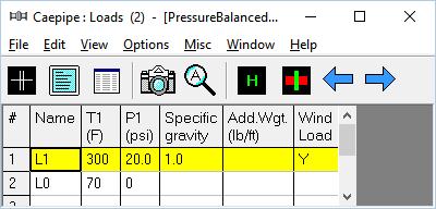
15 Example 6: Pressure Balanced Elbow Expansion Joint Pressure Balanced Elbow Expansion Joints can consist of a single or double bellows in the flow section, and a balancing bellow of equal area on the back side of the elbow. Tie rods attach the outboard end of the balancing bellow to the outboard end of the flow bellows. Under pressure, the tie rods are loaded with the pressure thrust force. If the flow bellows compresses in service, the balancing bellow extends by the same amount without exposing the adjacent anchors to pressure thrust forces. However, the spring forces associated with bellows movements are imposed on the adjacent equipment. A pressure balanced elbow type expansion joint can accept axial compression, axial extension, lateral movements and very limited angular motion. The sample model shown below simulates the Pressure Balanced Elbow Expansion Joint with Four Tie Rods using the CAEPIPE's Tie Rod elements. The stiffness of the tie rods can be input explicitly (in this case, stiffness corresponding to 1" dia tie rod is input). See snap shots below for details.

16

17
Tutorial on Qualification of Nozzles attached to Spherical/Cylindrical Vessels using CAEPIPE
 Tutorial on Qualification of Nozzles attached to Spherical/Cylindrical Vessels using CAEPIPE The following are the steps for qualifying nozzles welded to Spherical/Cylindrical Vessels such as pressure
Study of various flexible joints as the thermal compensator elements in a typical light transport aircraft engine bleed system
 Study of various flexible joints as the thermal compensator elements in a typical light transport aircraft engine bleed system Prashanth Banakara, H.T. Akshatha, M.L. Shankar and A. Rinku Abstract Engine
EXPANSION JOINT DESIGN GUIDE
 EXPANSION JOINT DESIGN GUIDE MODEL MN WITH SPECIAL FLANGES PRESSURE BALANCED MODEL MC MODEL MNLC DOUBLE END MODEL MC WITH ANCHOR BASE LINER MODEL MC MODEL MN WITH WELD ENDS WELDED DIAPHRAM-TYPE* MODEL
CAEPIPE. Tutorial for Modeling and Results Review Problem 1
 CAEPIPE Tutorial for Modeling and Results Review Problem 1 CAEPIPE Tutorial, 2018, SST Systems, Inc. All Rights Reserved. Disclaimer Please read the following carefully: This software and this manual have
 Set No. 1 IV B.Tech. I Semester Regular Examinations, November 2010 FINITE ELEMENT METHODS (Mechanical Engineering) Time: 3 Hours Max Marks: 80 Answer any FIVE Questions All Questions carry equal marks
A Strain Free Lock and Release Mechanism for an Elastically Suspended Two-Axis Gimbal
 A Strain Free Lock and Release Mechanism for an Elastically Suspended Two-Axis Gimbal Armond Asadurian Moog Inc., Chatsworth Operations, 21339 Nordhoff Street, Chatsworth, CA 91311 Tel: 001-818-341-5156
MULTI-SPRING REPRESENTATION OF FASTENERS FOR MSC/NASTRAN MODELING
 MULTI-SPRING REPRESENTATION OF FASTENERS FOR MSC/NASTRAN MODELING Alexander Rutman, Ph. D, Joseph Bales-Kogan, M. Sc. ** Boeing Commercial Airplane Group Strut Structures Technology MS K95-04 380 South
Development of Bellows Design Software using MATLAB
 Indian Journal of cience and Technology, Vol 8(8), 201 206, April 2015 IN (Print) : 097-686 IN (Online) : 097-565 DOI: 10.1785/ijst/2015/v8i8/70619 Development of Bellows Design oftware using MATLAB ungchul
Seismic-Initiated events risk mitigation in LEad cooled Reactors SILER How to isolate an NPP interface components: Metal Bellows Expansion joints
 Seismic-Initiated events risk mitigation in LEad cooled Reactors SILER How to isolate an NPP interface components: Metal Bellows Expansion joints What are Metal Bellows Expansion Joints Metal Bellows Expansion
Stainless Steel Bellows
 Stainless Steel Bellows Bellows Metallic Bellows Material : mostly 00 Series Stainless Steel Size range : (/ in.) to ( in.) Movement : to Flanged End Type - JF- Series Size range : 0 ( /in.) to 00 (in.)
Quality Since 1935 SERIES EXPANSION JOINTS WON T
 1-00-25-00 Quality Since 135 SERIES 0EZ EXPANSION JOINTS THEY PERFORM LIKE WON T YOU BELIEVE THE EVOLUTION OF ELASTOMERIC EXPANSION JOINT STYLES Standard Arch (The 130 s) Flowing Arch (The 170 s) Wide
Information Document
 Information Document SST Systems, Inc. produced this document for distribution to piping analysis software evaluators. Information contained herein is subject to change without prior notice. CAEPIPE and
LIGO Scissors Table Static Test and Analysis Results
 LIGO-T980125-00-D HYTEC-TN-LIGO-31 LIGO Scissors Table Static Test and Analysis Results Eric Swensen and Franz Biehl August 30, 1998 Abstract Static structural tests were conducted on the LIGO scissors
PD2CAEPIPE - Plant Design-to-CAEPIPE Translator
 PD2CAEPIPE - Plant Design-to-CAEPIPE Translator (for converting PCF files) 1.0 Installing Program To install PD2CAEPIPE on Windows NT, load the product CD supplied by InfoPlant and run the program "SETUP.EXE"
Tutorial 1: Welded Frame - Problem Description
 Tutorial 1: Welded Frame - Problem Description Introduction In this first tutorial, we will analyse a simple frame: firstly as a welded frame, and secondly as a pin jointed truss. In each case, we will
Background CE 342. Why RISA-2D? Availability
 Background CE 342 RISA-2D RISA-2D is a structural analysis program, which can model: Beams, frames, trusses and plates. Any linear elastic structural material. Typical supports, such as pins, rollers and
AUTOPIPE / CAESAR TRANSLATION
 AUTOPIPE / CAESAR TRANSLATION CONTENTS AutoPIPE / Caesar Translation... 1 Caesar Neutral File Versions... 2 Transfering Caesar Model to AutoPIPE... 3 Transfer Large Caesar Models... 9 AutoPIPE Configurable
D DAVID PUBLISHING. Stability Analysis of Tubular Steel Shores. 1. Introduction
 Journal of Civil Engineering and Architecture 1 (216) 563-567 doi: 1.17265/1934-7359/216.5.5 D DAVID PUBLISHING Fábio André Frutuoso Lopes, Fernando Artur Nogueira Silva, Romilde Almeida de Oliveira and
COSMOS. Connecting to Accurate, Efficient Assembly Analysis. SolidWorks Corporation. Introduction. Pin Connectors. Bolt Connectors.
 WHITE PAPER Connecting to Accurate, Efficient Assembly Analysis CONTENTS Introduction Pin Connectors Bolt Connectors Spring Connectors Spot Weld Connectors 1 2 4 7 8 SolidWorks Corporation INTRODUCTION
Global to Local Model Interface for Deepwater Top Tension Risers
 Global to Local Model Interface for Deepwater Top Tension Risers Mateusz Podskarbi Karan Kakar 2H Offshore Inc, Houston, TX Abstract The water depths from which oil and gas are being produced are reaching
DESIGN & ANALYSIS OF CONNECTING ROD OF FORMING AND CUTTING DIE PILLAR STATION OF VACUUM FORMING MACHINE
 Research Paper ISSN 2278 0149 www.ijmerr.com Vol. 3, No. 3, July, 2014 2014 IJMERR. All Rights Reserved DESIGN & ANALYSIS OF CONNECTING ROD OF FORMING AND CUTTING DIE PILLAR STATION OF VACUUM FORMING MACHINE
50 years of Reliable Field History
 COUPLING COMMENTS The No Maintenance, Easy Assembly, Resilient Coupling with High Angular Misalignment up to 0 degrees Center Assembly 70 Deg. Neoprene Rubber in Compression Grade 5 Bolts Steel Flanges
SAFI Sample Projects. Design of a Steel Structure. SAFI Quality Software Inc. 3393, chemin Sainte-Foy Ste-Foy, Quebec, G1X 1S7 Canada
 SAFI Sample Projects Design of a Steel Structure SAFI Quality Software Inc. 3393, chemin Sainte-Foy Ste-Foy, Quebec, G1X 1S7 Canada Contact: Rachik Elmaraghy, P.Eng., M.A.Sc. Tel.: 1-418-654-9454 1-800-810-9454
Multibody Dynamics Module
 Multibody Dynamics Module User s Guide VERSION 4.4 Multibody Dynamics Module User s Guide 1998 2013 COMSOL Protected by U.S. Patents 7,519,518; 7,596,474; 7,623,991; and 8,457,932. Patents pending. This
checkstress User s Manual
 TM checkstress User s Manual checkstress User s Manual, Server Version 9.xx, 2016, SST Systems, Inc. All rights reserved. Disclaimer Please read the following carefully: This software and this document
Quarter Symmetry Tank Stress (Draft 4 Oct 24 06)
") Quarter Symmetry Tank Stress (Draft 4 Oct 24 06) Introduction You need to carry out the stress analysis of an outdoor water tank. Since it has quarter symmetry you start by building only one-fourth of
Quarter Symmetry Tank Stress (Draft 4 Oct 24 06) Introduction You need to carry out the stress analysis of an outdoor water tank. Since it has quarter symmetry you start by building only one-fourth of
EXPANSION JOINT & FLEXIBLE PRODUCT
 EXPANSION JOINT & FLEXIBLE PRODUCT A. IAL EXPANSION JOINT MEGAFLEXON standard axial expansion joint are available in types MW, with weld ends, and MF with flanges. Axial Expansion joints are used in pipeline
Frame Analysis Using Visual Analysis
 Frame Analysis Using Visual Analysis 1. The software is available at the Open Access Labs (OAL) and the Virtual OAL at http://voal.tamu.edu in Programs under the Windows Start menu. The software can also
Learning Module 8 Shape Optimization
 Learning Module 8 Shape Optimization What is a Learning Module? Title Page Guide A Learning Module (LM) is a structured, concise, and self-sufficient learning resource. An LM provides the learner with
Introduction. Section 3: Structural Analysis Concepts - Review
 Introduction In this class we will focus on the structural analysis of framed structures. Framed structures consist of components with lengths that are significantly larger than crosssectional areas. We
= 21
 CE 331, Spring 2011 Guide for Using RISA3D to Model a Balsa Structure 1 / 9 0. Example Bridge. An example structure is shown below. Typical results for the RISA model of this structure are shown throughout
VARIOUS APPROACHES USED IN THE SEISMIC QUALIFICATION OF THE PIPING SYSTEMS IN NUCLEAR FACILITIES. Introduction
 VARIOUS APPROACHES USED IN THE SEISMIC QUALIFICATION OF THE PIPING SYSTEMS IN NUCLEAR FACILITIES A. Musil, P. Markov Stevenson&Associates, Pilsen, Czech Republic Introduction In the firm Stevenson&Associates
SIZES FROM 1, ,000 Nm BACKLASH FREE, TORSIONALLY STIFF METALLIC BELLOWS COUPLINGS
 BX ZA SIZES FROM 1,500-100,000 Nm BAKLASH FREE, TORSIONALLY STIFF METALLI BELLOWS OUPLINGS BELLOWS OUPLINGS BX ZA Optional: GENERAL INFORMATION ABOUT R+W BELLOWS OUPLINGS: SERVIE LIFE R+W bellows couplings
Tutorial. BOSfluids. Water hammer (part 1) Modeling
 Modeling") BOSfluids Tutorial Water hammer (part 1) Modeling The Water hammer tutorial is a 3 part tutorial describing the phenomena of water hammer in a piping system and how BOSfluids can be used to examine the
BOSfluids Tutorial Water hammer (part 1) Modeling The Water hammer tutorial is a 3 part tutorial describing the phenomena of water hammer in a piping system and how BOSfluids can be used to examine the
A05 Steel Catenary Riser Systems
 A05 Steel Catenary Riser Systems Introduction This example contains three examples of steel catenary risers (SCRs). These are: Catenary with Spar Catenary with SemiSub Lazy Wave with FPSO The example also
In-plane principal stress output in DIANA
 analys: linear static. class: large. constr: suppor. elemen: hx24l solid tp18l. load: edge elemen force node. materi: elasti isotro. option: direct. result: cauchy displa princi stress total. In-plane
KISSsoft 03/2013 Tutorial 5
 KISSsoft 03/2013 Tutorial 5 Shaft analysis KISSsoft AG Rosengartenstrasse 4 8608 Bubikon Switzerland Tel: +41 55 254 20 50 Fax: +41 55 254 20 51 info@kisssoft.ag www.kisssoft.ag Contents 1 Starting KISSsoft...
Analysis of Gas Duct Movement in Corex Process Y.P. Reddy 2, Sinhgad College of Engg, Pune
 Kedar Kulkarni 1, Sinhgad College of Engg, Pune Analysis of Gas Duct Movement in Corex Process Y.P. Reddy 2, Sinhgad College of Engg, Pune Vasantha Ramaswamy 3, Aprameya Associates, Pune Abstract This
Information Document
 Information Document SST Systems, Inc. produced this document for distribution to piping analysis software evaluators. Information contained herein is subject to change without prior notice. CAEPIPE and
Problem 1. Lab #12 Solution
 Lab #1 Solution Problem 1 Given Truss Roof Dead Load of 16 psf, Snow Live load of 16 psf, Truss spacing of 4" o.c. Lumber is No. DF-L Bolt holes are 7/" diameter, MC < 19%, Temp < 100 degree F, and Ci
Connection Elements and Connection Library
 Connection Elements and Connection Library Lecture 2 L2.2 Overview Introduction Defining Connector Elements Understanding Connector Sections Understanding Connection Types Understanding Connector Local
Journal of Engineering Science and Technology Review 8 (6) (2015) 1-5 Special Issue on Simulation of Manufacturing Technologies. Conference Article
 (2015) 1-5 Special Issue on Simulation of Manufacturing Technologies. Conference Article") Jestr Journal of Engineering Science and Technology Review 8 () (2015) 1-5 Special Issue on Simulation of Manufacturing Technologies Conference Article JOURNAL OF Engineering Science and Technology Review
Jestr Journal of Engineering Science and Technology Review 8 () (2015) 1-5 Special Issue on Simulation of Manufacturing Technologies Conference Article JOURNAL OF Engineering Science and Technology Review
Technical Report Example (1) Chartered (CEng) Membership
 Chartered (CEng) Membership") Technical Report Example (1) Chartered (CEng) Membership A TECHNICAL REPORT IN SUPPORT OF APPLICATION FOR CHARTERED MEMBERSHIP OF IGEM DESIGN OF 600 (103 BAR) 820MM SELF SEALING REPAIR CLAMP AND VERIFICATION
Technical Report Example (1) Chartered (CEng) Membership A TECHNICAL REPORT IN SUPPORT OF APPLICATION FOR CHARTERED MEMBERSHIP OF IGEM DESIGN OF 600 (103 BAR) 820MM SELF SEALING REPAIR CLAMP AND VERIFICATION
ixcube 4-10 Brief introduction for membrane and cable systems.
 ixcube 4-10 Brief introduction for membrane and cable systems. ixcube is the evolution of 20 years of R&D in the field of membrane structures so it takes a while to understand the basic features. You must
CITY AND GUILDS 9210 UNIT 135 MECHANICS OF SOLIDS Level 6 TUTORIAL 15 - FINITE ELEMENT ANALYSIS - PART 1
 Outcome 1 The learner can: CITY AND GUILDS 9210 UNIT 135 MECHANICS OF SOLIDS Level 6 TUTORIAL 15 - FINITE ELEMENT ANALYSIS - PART 1 Calculate stresses, strain and deflections in a range of components under
This is NOT a truss, this is a frame, consisting of beam elements. This changes several things
 CES 44 - Stress Analysis Spring 999 Ex. #, the following -D frame is to be analyzed using Sstan (read the online stan intro first, and Ch-6 in Hoit) 5 k 9 E= 9000 ksi 8 I= 600 in*in*in*in 5 A= 0 in*in
Top Layer Subframe and Node Analysis
 Top Layer Subframe and Node Analysis By Paul Rasmussen 2 August, 2012 Introduction The top layer of the CCAT backing structure forms a critical interface between the truss and the primary subframes. Ideally
ANALYSIS AND OPTIMIZATION OF CONNECTING ROD BY FEA
 ANALYSIS AND OPTIMIZATION OF CONNECTING ROD BY FEA 1 Mr.Ajit Lonkar 1 M-Tech Student dept CAD/CAM 1 Narayana Technical Campus, Telangana, India[Affiliated to JNTU, Approved by AICTE] ABSTRACT: The automobile
TRIFLEX Windows Enhancements & Modifications 16 February 2002
 Enhancements 1. Euro Code - In TRIFLEX Windows Release 1.6.0, the requirements of the new Euro Piping Code have been incorporated. The User will now be able to quickly check compliance with the new Euro
Master and Slave Nodes (Rigid Link Function)
") Master and Slave Nodes (Rigid Link Function) The rigid link function specified in Model>Boundaries>Rigid Link constrains geometric, relative movements of a structure. Geometric constraints of relative
Master and Slave Nodes (Rigid Link Function) The rigid link function specified in Model>Boundaries>Rigid Link constrains geometric, relative movements of a structure. Geometric constraints of relative
5. Finite Element Analysis of Bellows
 5. Finite Element Analysis of Bellows 5.1 Introduction: Traditional design process and stress analysis techniques are very specific for each individual case based on fundamental principles. It can only
Module 1: Introduction to Finite Element Analysis. Lecture 4: Steps in Finite Element Analysis
 25 Module 1: Introduction to Finite Element Analysis Lecture 4: Steps in Finite Element Analysis 1.4.1 Loading Conditions There are multiple loading conditions which may be applied to a system. The load
midas Civil Advanced Webinar Date: February 9th, 2012 Topic: General Use of midas Civil Presenter: Abhishek Das Bridging Your Innovations to Realities
 Advanced Webinar Date: February 9th, 2012 Topic: General Use of midas Civil Presenter: Abhishek Das Contents: Overview Modeling Boundary Conditions Loading Analysis Results Design and Misc. Introduction
Compact Bellows Pumps
 Compact Bellows Pumps Compact Bellows Metering Pumps were specifically designed for metering applications requiring low discharge pressures. Compact pumps have been successfully applied in photo, X-ray
P07110 Vertical Test Stand. Concept Review
 P07110 Vertical Test Stand Concept Review Last year, a Senior Design team designed and built a horizontal rocket test stand. Many useful lessons were learned from this effort and there exists the potential
Part 2: PowerFrame Reference Manual
 Part 2: PowerFrame Reference Manual 2006, BuildSoft NV All rights reserved. No part of this document may be reproduced or transmitted in any form or by any means, electronic or manual, for any purpose
Duo-Pro Double Contained Piping Systems
 PRO 150x150 Simultaneous Pipe Part Number 5210+(size code) (ft.) L2 (ft.) # Spider Clips 1 x 3 (134) 3.75 2.5 4 2 x 4 (420) 3.50 3.0 4 3 x 6 (531) 5.25 3.0 3 4 x 8 (583) 5.25 3.0 3 6 x 10 (627) 5.25 3.0
Frame Analysis. Frame Analysis 1
 Frame Analysis 1Introduction... 7 1.1 Generally... 7 2 Program organization... 9 2.1 Main menu... 10 2.1.1 Input geometry... 11 2.1.1.1 File... 12 2.1.1.2 Edit... 13 2.1.1.3 View... 13 2.1.1.4 Input...
Distance Between Two Snaked-lay of Subsea Pipeline. Yuxiao Liu1, a *
 International Conference on Manufacturing Science and Engineering (ICMSE 21) Distance Between Two Snaked-lay of Subsea Pipeline Yuxiao Liu1, a * 1,Dept. of Management Since and Engineering,Shandong Institute
Orbital forming of SKF's hub bearing units
 Orbital forming of SKF's hub bearing units Edin Omerspahic 1, Johan Facht 1, Anders Bernhardsson 2 1 Manufacturing Development Centre, AB SKF 2 DYNAmore Nordic 1 Background Orbital forming is an incremental
B01 Drilling Riser. Orcina. 1. Building the model
 B01 Drilling Riser A tensioned drilling riser descends from a semi-submersible drilling vessel to a BOP (blow out preventer) on the seabed. A drill string is modelled running inside the riser down to the
Application nr. 2 (Global Analysis) Effects of deformed geometry of the structures. Structural stability of frames. Sway frames and non-sway frames.
 Effects of deformed geometry of the structures. Structural stability of frames. Sway frames and non-sway frames.") Application nr. 2 (Global Analysis) Effects of deformed geometry of the structures. Structural stability of frames. Sway frames and non-sway frames. Object of study: multistorey structure (SAP 2000 Nonlinear)
Application nr. 2 (Global Analysis) Effects of deformed geometry of the structures. Structural stability of frames. Sway frames and non-sway frames. Object of study: multistorey structure (SAP 2000 Nonlinear)
COSMOSWorks Verification
 2006 COSMOSWorks Verification COSMOSWorks Verification Problems This document contains verification problems to demonstrate the accuracy of the COMSOSWorks software in comparison to analytical results.
Bellows. Technical Principles Bellows
 Technical Principles Bellows Bellows Technical Principles Bellows 704 Use of Bellows 706 Products Products 710 Design Types 711 Freudenberg Simrit GmbH & Co. KG Technical Principles 703 Technical Principles
THRUSTER ORIENTATION MECHANISM. Sami Mankaï
 THRUSTER ORIENTATION MECHANISM Sami Mankaï Alcatel space industries 100 Boulevard du Midi, BP 99-06156 Cannes la Bocca Cedex Telephone : 33-(0)4-92-92-79-76 / Fax : 33-(0)4-92-92-60-20 E-mail : sami.mankai@space.alcatel.fr
Example Lecture 12: The Stiffness Method Prismatic Beams. Consider again the two span beam previously discussed and determine
 Example 1.1 Consider again the two span beam previously discussed and determine The shearing force M1 at end B of member B. The bending moment M at end B of member B. The shearing force M3 at end B of
ME Optimization of a Frame
 ME 475 - Optimization of a Frame Analysis Problem Statement: The following problem will be analyzed using Abaqus. 4 7 7 5,000 N 5,000 N 0,000 N 6 6 4 3 5 5 4 4 3 3 Figure. Full frame geometry and loading
SUBMERGED CONSTRUCTION OF AN EXCAVATION
 2 SUBMERGED CONSTRUCTION OF AN EXCAVATION This tutorial illustrates the use of PLAXIS for the analysis of submerged construction of an excavation. Most of the program features that were used in Tutorial
SolidWorks. An Overview of SolidWorks and Its Associated Analysis Programs
 An Overview of SolidWorks and Its Associated Analysis Programs prepared by Prof. D. Xue University of Calgary SolidWorks - a solid modeling CAD tool. COSMOSWorks - a design analysis system fully integrated
Coupling Dimensions Bolts Max. End. Allow Pipe Outside. Load Size Dia. End Sep. A B C No. Size x Length kg
 OUPLINGS Style Reducing oupling Features Reducing oupling provides direct reduction on the pipingrun, without any accesories onsists of reducing gaskets and a steel washer which prevents entry of the smaller
PLAXIS 2D - SUBMERGED CONSTRUCTION OF AN EXCAVATION
 PLAXIS 2D - SUBMERGED CONSTRUCTION OF AN EXCAVATION 3 SUBMERGED CONSTRUCTION OF AN EXCAVATION This tutorial illustrates the use of PLAXIS for the analysis of submerged construction of an excavation. Most
ANSYS AIM Tutorial Structural Analysis of a Plate with Hole
 ANSYS AIM Tutorial Structural Analysis of a Plate with Hole Author(s): Sebastian Vecchi, ANSYS Created using ANSYS AIM 18.1 Problem Specification Pre-Analysis & Start Up Analytical vs. Numerical Approaches
ANSYS Element. elearning. Peter Barrett October CAE Associates Inc. and ANSYS Inc. All rights reserved.
 ANSYS Element Selection elearning Peter Barrett October 2012 2012 CAE Associates Inc. and ANSYS Inc. All rights reserved. ANSYS Element Selection What is the best element type(s) for my analysis? Best
STRUCTURAL ANALYSIS - II
 STRUCTURAL ANALYSIS - II SYLLABUS UNIT-I: MOMENT DISTRIBUTION METHOD Analysis of Single Bay Single Storey Portal Frame including side Sway. Analysis of inclined Frames. Kani s Method: Analysis of Continuous
FB-MULTIPIER vs ADINA VALIDATION MODELING
 FB-MULTIPIER vs ADINA VALIDATION MODELING 1. INTRODUCTION 1.1 Purpose of FB-MultiPier Validation testing Performing validation of structural analysis software delineates the capabilities and limitations
Finite Element Model for Axial Stiffness of Metal-Plate-Connected Tension Splice Wood Truss Joint
 Finite Element Model for Axial Stiffness of Metal-Plate-Connected Tension Splice Wood Truss Joint Jose M. Cabrero Assistant Professor University of Navarra, Department of Structural Analysis and Design,
ME scope Application Note 04 Using SDM for Sub-Structuring
 App Note 04 www.vibetech.com 2-Aug-18 ME scope Application Note 04 Using SDM for Sub-Structuring NOTE: The steps in this Application Note can be duplicated using any Package that includes the VES-5000
Stress Analysis of Cross Groove Type Constant Velocity Joint
 TECHNICAL REPORT Stress Analysis of Cross Groove Type Constant Velocity Joint H. SAITO T. MAEDA The driveshaft is the part that transmits the vehicle's engine torque and rotation to the tires, and predicting
Non-Linear Analysis of Bolted Flush End-Plate Steel Beam-to-Column Connection Nur Ashikin Latip, Redzuan Abdulla
 Non-Linear Analysis of Bolted Flush End-Plate Steel Beam-to-Column Connection Nur Ashikin Latip, Redzuan Abdulla 1 Faculty of Civil Engineering, Universiti Teknologi Malaysia, Malaysia redzuan@utm.my Keywords:
Lateral Loading of Suction Pile in 3D
 Lateral Loading of Suction Pile in 3D Buoy Chain Sea Bed Suction Pile Integrated Solver Optimized for the next generation 64-bit platform Finite Element Solutions for Geotechnical Engineering 00 Overview
EXACT BUCKLING SOLUTION OF COMPOSITE WEB/FLANGE ASSEMBLY
 EXACT BUCKLING SOLUTION OF COMPOSITE WEB/FLANGE ASSEMBLY J. Sauvé 1*, M. Dubé 1, F. Dervault 2, G. Corriveau 2 1 Ecole de technologie superieure, Montreal, Canada 2 Airframe stress, Advanced Structures,
FEA BENDING, TORSION, TENSION, and SHEAR TUTORIAL in CATIA
 1 FEA BENDING, TORSION, TENSION, and SHEAR TUTORIAL in CATIA This tutorial shows the basics of a solid bending, torsional, tension, and shear FEA (Finite Elemental Analysis) model in CATIA. Torsion - page
NOVEL DOUBLE ROLLER BEARING FE ANALYSIS AND COMPARISON WITH CONVENTIONAL DOUBLE ROW CYLINDRICAL ROLLER BEARING
 International Journal of Design and Manufacturing Technology (IJDMT) Volume 6, Issue 2, July-December 2015, pp. 19-29, Article ID: 30320150602004 Available online at http://www.iaeme.com/currentissue.asp?jtype=ijdmt&vtype=6&itype=2
Advanced model of steel joints loaded by internal forces from 3D frame structures
 Advanced model of steel joints loaded by internal forces from 3D frame structures Lubomír Šabatka, IDEA RS s.r.o František Wald, FSv ČVUT Praha Jaromír Kabeláč, Hypatia Solutions s.r.o Drahoslav Kolaja,
Lesson: Static Stress Analysis of a Connecting Rod Assembly
 Lesson: Static Stress Analysis of a Connecting Rod Assembly In this tutorial we determine the effects of a 2,000 pound tensile load acting on a connecting rod assembly (consisting of the rod and two pins).
Engineering Effects of Boundary Conditions (Fixtures and Temperatures) J.E. Akin, Rice University, Mechanical Engineering
 J.E. Akin, Rice University, Mechanical Engineering") Engineering Effects of Boundary Conditions (Fixtures and Temperatures) J.E. Akin, Rice University, Mechanical Engineering Here SolidWorks stress simulation tutorials will be re-visited to show how they
Engineering Effects of Boundary Conditions (Fixtures and Temperatures) J.E. Akin, Rice University, Mechanical Engineering Here SolidWorks stress simulation tutorials will be re-visited to show how they
90 Elbows Long Radius
 90 Elbows Long Radius DN O.D. Center SCH STD SCH XS SCH XXS SCH 10 SCH 20 SCH 30 SCH 40 SCH 60 SCH 80 SCH 100 SCH 120 SCH 160 Inch mm to End Thickness Weight Thickness Weight Thickness Weight Thickness
Guidelines for proper use of Plate elements
 Guidelines for proper use of Plate elements In structural analysis using finite element method, the analysis model is created by dividing the entire structure into finite elements. This procedure is known
NUMERICAL ANALYSIS OF ROLLER BEARING
 Applied Computer Science, vol. 12, no. 1, pp. 5 16 Submitted: 2016-02-09 Revised: 2016-03-03 Accepted: 2016-03-11 tapered roller bearing, dynamic simulation, axial load force Róbert KOHÁR *, Frantisek
Vacuum Maintenance Manual (EXCERPT Tim Benedict)
") 1. Position a ladder, scaffold, or work stand, on the right side of Vacuum Skid where the blower motors are installed. 2. Locate the six (6) vacuum hoses connecting the blower motors to the HEPA housings
1. Position a ladder, scaffold, or work stand, on the right side of Vacuum Skid where the blower motors are installed. 2. Locate the six (6) vacuum hoses connecting the blower motors to the HEPA housings
Modelling of mechanical system CREATING OF KINEMATIC CHAINS
 Modelling of mechanical system CREATING OF KINEMATIC CHAINS Mechanism Definitions 1. a system or structure of moving parts that performs some function 2. is each system reciprocally joined moveable bodies
SolidWorks Motion Study Tutorial
 SolidWorks Motion Study Tutorial By: Mohamed Hakeem Mohamed Nizar Mechanical Engineering Student- May 2015 South Dakota School of Mines & Technology August 2013 Getting Started This tutorial is for you
Modeling and Measuring Dynamic Well Intervention Stack Stress Ed Smalley, SPE, CTES, L.P.; Ken Newman, SPE, CTES, L.P.; Rodney Stephens, SPE, BP
 SPE 94233 Modeling and Measuring Dynamic Well Intervention Stack Stress Ed Smalley, SPE, CTES, L.P.; Ken Newman, SPE, CTES, L.P.; Rodney Stephens, SPE, BP Copyright 2005, Society of Petroleum Engineers
DETC2002/MECH DESIGN OF LARGE-DISPLACEMENT COMPLIANT JOINTS
 Proceedings of DETC ASME Design Engineering Technical Conferences and Computers and Information in Engineering Conference Montreal, Canada, September 9-October, Than you for using our wor. When referencing
Simplified modeling for needle roller bearings to analyze engineering structures by FEM
 Ŕ periodica polytechnica Mechanical Engineering 54/1 (2010) 27 33 doi: 10.3311/pp.me.2010-1.05 web: http:// www.pp.bme.hu/ me c Periodica Polytechnica 2010 Simplified modeling for needle roller bearings
Stress Analysis of thick wall bellows using Finite Element Method
 Stress Analysis of thick wall bellows using Finite Element Method Digambar J. Pachpande Post Graduate Student Department of Mechanical Engineering V.J.T.I. Mumbai, India Prof. G. U. Tembhare Assistant
Keywords: Micromirror, MEMS, electrostatic torque, serpentine spring, restoring torque, coupled field analysis. 2. MICROMIRROR STRUCTURE AND DESIGN
 Design and Analysis of the performance of a Torsional Micromirror for an Optical switching system Ajay A. Kardak *, Prasant Kumar Patnaik, T. Srinivas, Navakanta Bhat and A. Selvarajan National MEMS Design
Revision of the SolidWorks Variable Pressure Simulation Tutorial J.E. Akin, Rice University, Mechanical Engineering. Introduction
 Revision of the SolidWorks Variable Pressure Simulation Tutorial J.E. Akin, Rice University, Mechanical Engineering Introduction A SolidWorks simulation tutorial is just intended to illustrate where to
SOEM 024: Computer Aided Design. E. Rozos
 SOEM 024: Computer Aided Design E. Rozos Lesson structure Construct 3D objects with revolving WCS UCS Master plotting Realism Geometrical analysis Stress analysis Kinematics dynamic simulation Revolve,
Chapter 3 Analysis of Original Steel Post
 Chapter 3. Analysis of original steel post 35 Chapter 3 Analysis of Original Steel Post This type of post is a real functioning structure. It is in service throughout the rail network of Spain as part